Article

Flight Dynamic Characteristics of Wide-Body Aircraft with Wind Gust and Turbulence

by
Kashif Mehmood
1,
Syed Irtiza Ali Shah
2,
Taimur Ali Shams
1,
Muhammad Nafees Mumtaz Qadri
1,
Tariq Amin Khan
1 and
David Kukulka
3,*
1
Department of Aerospace Engineering, College of Aeronautical Engineering, National University of Sciences and Technology, Islamabad 44000, Pakistan
2
Department of Mechanical & Aerospace Engineering, Air University, Islamabad 44000, Pakistan
3
Department of Mechanical Engineering, State University of New York College at Buffalo, 1300 Elmwood Avenue, Buffalo, NY 14222, USA
*
Author to whom correspondence should be addressed.
Fluids 2023, 8(12), 320; https://doi.org/10.3390/fluids8120320
Submission received: 19 October 2023 / Revised: 6 December 2023 / Accepted: 8 December 2023 / Published: 16 December 2023

Abstract

:
In this research, a wide-body aircraft was analyzed with critical monitoring of its states, a function of several control inputs (wind gust, turbulence, and microburst). The aerodynamic and stability coefficients of a Boeing 747-200 were obtained from previously published works and 6- DOF equations were formulated. Simulations were conducted for various control inputs to determine the aircraft’s free response, as well as the forced response. In order to understand the nature of the atmosphere, three different models were incorporated, including (i) the Dryden Model, (ii) wind gust, and (iii) microburst. The aircraft was found to be stable in the longitudinal and lateral flight modes, with trim conditions agreeing with published data. For a vertical wind gust of −10 ft/s, the AoA and pitch rate were observed to oscillate sinusoidally and became stable with new trim conditions. These states were found to regain trim conditions once the gust was removed. In the case of 3D gust, it was found that the longitudinal modes achieved a new trim condition through Phugoid oscillations, whereas the lateral modes underwent short-period oscillations. For the case of turbulence, random fluctuations were observed for trim conditions with no unstable behavior. When considering the microburst case, it was found that the aircraft initially gained altitude in the region of the headwind; this was followed by a sharp descent under the influence of a vertical velocity component.

1. Introduction

Aircraft stability and control analysis is one of the most important aspects of the aircraft design process. This is especially important with the advent of flights at high speed and high angles of attack (AoAs); thus, the importance of stability and control analysis has increased. A well-designed aircraft with excellent performance features can be rejected if it has poor flying qualities (these are directly related to aircraft stability and control features). Therefore, designers introduce stability and control analysis early in the design process. Classically, the stability of an aircraft has been divided into static and dynamic stability. Static stability deals with the initial tendency of the aircraft after being disturbed from its equilibrium/trimmed position, while dynamic stability is the time history of the aircraft’s motion after being disturbed from the equilibrium/trim position. An aircraft may be statically stable and dynamically unstable; however, static stability is a prerequisite for dynamic stability. In this study, the term stability is used to represent the dynamic stability of the aircraft.
Aircraft stability and control analysis is a complex process. In preliminary analysis, the aircraft is treated as a rigid body in order to avoid complexities arising due to the structural flexibility of the aircraft’s main components (i.e., wings, tails, etc.). Using Newton’s second law and the Euler equations, the aircraft’s behavior is examined when influenced by external forces. The parameters are transformed from an inertial frame to a rotating body frame (Coriolis Effect) in order to reduce the mathematical complexity of the equations. For preliminary design analysis, a rigid body assumption provides good insight into the aircraft’s dynamics response; however, for final design, the effect of aeroelasticity must be included in aircraft stability and control analysis in order to account for the variation in the aerodynamics behavior of elastic structures.
Stability analysis starts with the acquisition of stability and control derivatives for the aircraft; this is accomplished through exhaustive wind tunnel testing and/or computational analysis. These derivatives are used in the formulation of 6-DOF non-linear equations; they are used to acquire trim conditions for the various flight phases of the aircraft. The linearized version of 6-DOF equations (which decouple the longitudinal set of equations from lateral) is frequently used in stability analysis to ascertain aircraft-free and forced responses to various types of control/environmental inputs under trim conditions. Stability analysis itself is a cumbersome process; additionally, contradictory design requirements, unconventional aircraft design, atmospheric turbulence, etc., add further complexity to the stability analysis process. A large amount of research work has been conducted in these areas; additional studies are still in progress in order to gain more insight into non-linear flight dynamics and unconventional designs; these will automate and link stability analysis early in the aircraft design cycle.

1.1. Stability and Performance Optimization—A Design Dilemma

Aircraft stability and performance are strongly dependent on aircraft design features; contradictory design requirements challenge the designer to optimize various design features that ensure flight safety while designing for optimum performance. Conventional aircraft were traditionally designed with inherent stability features that compromised on the performance aspect; however, with the advancement in computational techniques (for nonlinear aerodynamics and control theory), unstable (close-loop stable) or less stable aircraft designs are more popular in order to enhance the performance and maneuverability of the aircraft. This increasing trend (designs that lean toward augmented stability and expanded flight envelopes) requires an accurate estimation of aircraft dynamic behavior in order to properly design and integrate the flight control system (FCS). Thus, requiring in-depth knowledge and early estimation of aircraft stability and control features in the design and development cycle is a must for designs that are “first-time right” [1].

1.2. Extended Flight Envelope and Unconventional Aircraft Design

Advancements in computational techniques and hardware to support such analysis have brought a revolution in non-linear aerodynamics associated with innovative, unconventional configurations that a not possible with classical methods of analysis. Non-linear flight dynamics were first analyzed through advanced computational methods by [2,3] using bifurcation analysis and catastrophe theory methodology (BACTM) for capturing flight dynamics at high angles of attack. Additionally, several other studies [4,5,6,7,8,9,10,11,12,13] have further demonstrated the efficiency of these computational methods in analyzing applications related to open and closed-loop aircraft dynamics pre- and post-departure from the controlled flight regime. Finally, [14,15] applied control theory to design feedback controllers for nonlinear systems and verified their work through computer simulations. All these studies were performed for conventionally designed aircraft.
In the unconventional design domain, Bras et al. [16] worked on computing the flight dynamics characteristics of tailless aircraft configurations, whereas Morris et al. [17] presented a multidisciplinary optimization framework for supersonic tailless aircraft. However, these works [16,17] were restricted to longitudinal modes only and aerodynamic coefficients were derived using the Digital DATCOM [18] method. Flight dynamic analysis of unconventional configurations (i.e., three surface aircraft (TSA) and tandem wing configurations) was performed by [19,20]. Mader and Martins [21] analyzed the flying wing configurations using stability constraints with aerodynamic shape optimization.

1.3. Atmospheric Influence on Stability

Another factor that adds to the complexity of the analysis is the atmospheric interactions with the aircraft’s dynamics in which the aircraft is being operated. Atmospheric conditions (i.e., wind shear, gust, turbulence, etc.) vary at every location and time; the interaction of these atmospheric conditions with aircraft dynamics constantly poses a danger to aircraft control; this is especially true when in close proximity to the ground where the reaction time is very short. Various studies have been conducted on (i) the effect of wind shear and/or turbulence on flight dynamics; (ii) how to avoid these phenomena; and (iii) how to recover from these effects once they are encountered. In these studies, small downbursts (down drift wind shear) were categorized as serious hazards for aircraft during landing and takeoff. These low-altitude wind variations were a major contributing factor to aircraft crashes during the period from 1964 to 1985. Almost 26 major commercial airline accidents in the U.S. were attributed to wind shear; these led to a total of 620 deaths and 200 injuries [22]. The Federal Aviation Administration finally accepted the “downburst” concept presented by Dr. Ted Fujita of the University of Chicago and detailed in [23]. Safety measures (procedures to avoid and recover from such hazards) were part of pilots’ training; additionally, the installation of equipment that provided the timely prediction of this type of weather condition was implemented. With the implementation of these safety measures, accidents practically disappeared [23]. Figure 1 presents a pictorial representation of a microburst and its effect on aircraft landing/takeoff. As shown in Figure 1, the aircraft is approaching the runway (while maintaining a standard glide slope of 3°) and encounters a microburst. At this point, the aircraft will experience an increase in airspeed (due to the headwinds), producing an increase in lift and altitude; this is followed by a downburst that can suddenly decrease the aircraft’s altitude. The last phase comprises the tailwind; if the speed of the aircraft is not increased before entering the last phase, the tailwind would further decrease the airspeed, resulting in a sudden decrease in lift and altitude, leading to uncontrolled flight into the terrain. During takeoff (if the aircraft’s throttle is not managed in time), the existing phase would again culminate in aircraft stall. From the above description, the control variables needed to be manipulated for a controlled recovery flight can be obtained; these include throttle setting (thrust or airspeed management) and relative angle of attack.
Several studies have been conducted to analyze the behavior of aircraft under wind shear conditions (especially landing and takeoff phases) and determine suitable remedial actions for recovery. Some researchers have employed an optimal control approach [24], while others have adopted an inverse scheme for obtaining adequate control laws (for a range of wind shear intensities) that ensure survival [25]. All these studies were based on an assumed model for wind shear. In [26], no wind shear model was employed; however, it was assumed that wind shear properties had known bounds. Leitmann et al. [26] derived guidance schemes for crash avoidance based on robust control theory. In the above studies, the thrust was assumed to be set at maximum value during take-off. A different approach was adopted in [27], where it was assumed that the wind velocity field was known; for all possible wind shear conditions, they used viability theory to obtain initial conditions for which safe aircraft trajectories existed. In [28], the authors used estimated wind shear components along with various feed-forward and backward concepts for controlling B-727 aircraft during the landing approach under a microburst profile. Their work was primarily based on tracking airspeed changes and the glide slope of the aircraft. It was concluded that down drifts were difficult to counter as compared with horizontal wind shear. In [29], the authors effectively utilized the theory of differential games in order to present a viable solution for the problem of aircraft take-off in the presence of wind disturbances. In this study, the aircraft was assumed to be a nonlinear point mass that was linearized at small sub-intervals around an appropriate ascending trajectory. For each sub-interval, the linearized system was pitched against the wind using differential game strategies. Later, the linearized system was converted into a nonlinear system based on the feedback control found in these games. Through the repetition of procedures for every short interval, the authors demonstrated that they were able to hold on to the trajectory, despite variations in wind.

1.4. Flight Dynamic Models

Flight dynamics modeling is specialized and specific to the type of aircraft. Typically, models that include flight dynamics are proprietary and are generally not available. However, sometimes, mathematical models with limited functionality have been shared publicly in some studies. A literature survey was conducted for open-source flight dynamic simulation models that have been used for landing and take-off; no such models were found that could capture aircraft landing and takeoff in multiple wind scenarios. Several researchers [30,31,32,33,34] have presented simplified aerodynamics models (for generic aircraft) that calculate aerodynamics and control derivatives; being generic in nature, these models lack accuracy. Mathematical formulations are available to build flight dynamic models; however, these mathematical models require aerodynamic and stability parameters to be specific inputs for the aircraft under consideration. These parameters can be acquired using multiple sources that have various degrees of accuracy. Several studies [35,36,37,38] have used computational techniques, wind tunnel data, analytical formulations, and DATCOM (empirical) for the generation of the required data. Additionally, as previously discussed, during landing and takeoff, the aircraft is in close proximity to the ground; this further influences the aircraft’s aerodynamics and stability behavior. Several studies [39,40,41,42,43,44] have discussed the flow physics associated with various types of ground effects; they predicted the effects of various ground effects on the aerodynamics and stability parameters.
As previously discussed, many investigators have studied aircraft flight dynamics, unconventional designs, elasticity effects, and interactions with atmospheric variations; however, they were typically standalone and performed at a later stage in the design cycle (a point where maximum design freedom is already lost). The purpose of the present work was to formulate a simple MATLAB-based Simulink canvas that could provide feedback on the stability and control aspects of proposed aircraft designs during early design stages (conceptual and preliminary stages). To make the analysis more realistic, real-time temperature, density, and gravity variations were incorporated into the scheme using the MATLAB® COESA atmospheric Block Set [45]. The stability derivatives for initial studies can easily be acquired using DATCOM for the proposed aircraft design. This would enable the designer to be “first-time right” with the FCS design architecture. This simulation can be used for a complete stability assessment and the development of auto-pilot during the early development phase of the aircraft; additionally, it can be utilized during detailed design cycles once the actual derivatives are available after extensive wind tunnel testing/CFD simulation of the final design.

2. Aircraft Non-Linear Dynamics

2.1. Equations of Motion (EOMs)

Equations of motion (EOMs) are formulated with rigid body assumptions, as explained above. Newton’s second law is applied to a rigid body in a nonrotating frame; this states that the summation of external forces on any arbitrary body is equal to the rate of change of the linear momentum. Euler further enhanced Newton’s second law and added the summation of moments on the body; this is equal to the rate of change of the angular moment of a body. These equations are given as:
F = d d t m V = m d d t V = m u ˙ v ˙ w ˙
M = d d t H = d d t I ω = I x I x y I x z I y x I y I y z I z x I z y I z p ˙ q ˙ r ˙
If the reference frame is not rotating, then as the airplane rotates, the moments and inertia of the aircraft will vary with time. The body frame of the aircraft is always rotating with angular velocity, ω, with respect to the inertial frame. Calculating derivatives in such a complex rotating frame is difficult. In order to avoid this difficulty, the axes system is fixed to the aircraft body and derivatives are determined. These derivatives are then transformed to the fixed inertial frame using the mathematical expression presented below:
d A d t | I = d A d t | B + ω × A
Where A|I is measured with respect to or from the inertial frame and A|B is measured with respect to or from the body frame. All terms must be expressed in the same coordinates or along the same unit vector (as discussed in [46]). If not, use the direction cosine rotation matrix to bring it along the same unit vectors as LHS. Equation (4) shows the final form of the force and moment equations:
F = m   d V d t | B + m ω × V         M = d H d t | B + ω × H         w h e r e   H = I   ω
The transformation from inertia to body frame and back is governed by the transformation matrix based on Euler’s angle. The inertia tensor (I) for the aircraft in the body frame is shown in Equation (5). The terms Ix, Iy, and Iz are the moments of inertia with Ixz being the product of inertia. Usually, Ixy and Iyz are zeros for aircraft due to the inherent symmetry of the xz-plane. The transformation matrix for angular velocities, Euler’s angles, and the transformation matrix for inertia to body frame are given in Equations (6) and (7).
I = I x 0 I x z 0 I y 0 I x z 0 I z
ϕ ˙ θ ˙ ψ ˙ = 1 s i n ϕ t a n θ c o s ϕ t a n θ 0 c o s ϕ s i n ϕ 0 s i n ϕ / c o s θ c o s ϕ / c o s θ p q r
R b / i = 1 0 0 0 c o s ϕ s i n ϕ 0 s i n ϕ c o s ϕ c o s θ 0 s i n θ 0 1 0 s i n θ 0 c o s θ c o s ψ s i n ψ 0 s i n ψ c o s ψ 0 0 0 1
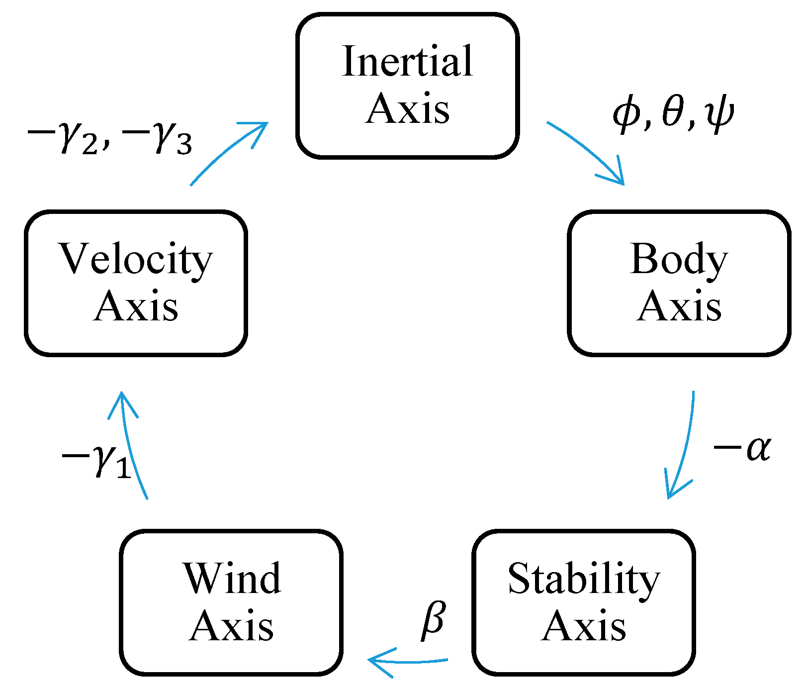
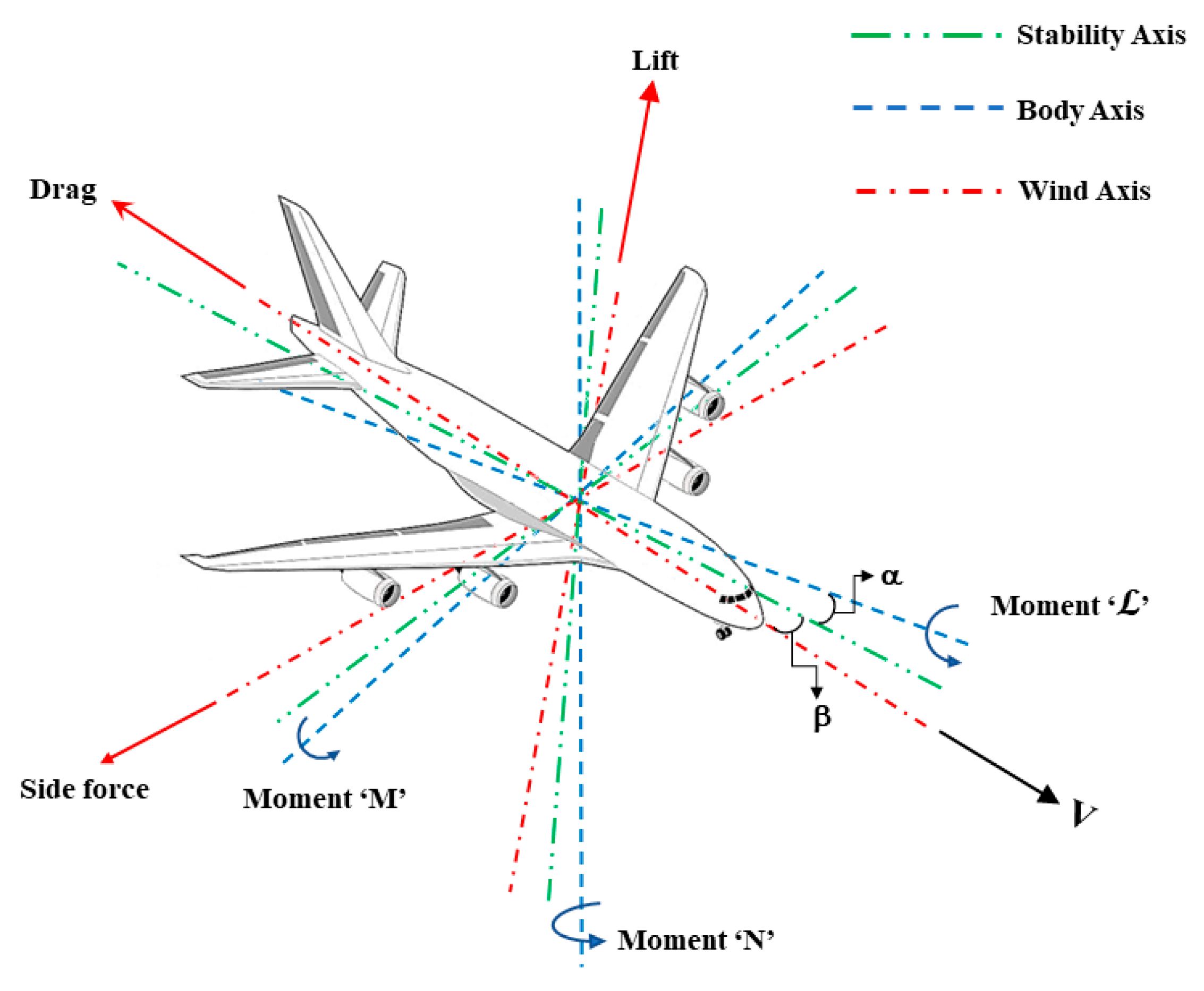
Aerodynamic forces (lift, drag, and side force) are usually captured using the wind axes or the stability axis; they need to be transformed to the body frame (Fx, Fy, and Fz) for the formulation of the 6-DOF equations (ref. Figure 2). These transformations involve rotations through the angle of attack (α) and side slip angle (β). The definitions of α and β involved in these rotation matrices are provided in Equation (8). Moments are generally calculated about the center of gravity (CG) of the aircraft.
α = tan 1 w u            β = sin 1 v V         w h e r e   V = u 2 + v 2 + w 2
Generally, the X, Y, and Z forces include aerodynamics and propulsion forces. If the propulsion forces are not in line with the body frame axis, then the propulsive forces need to be transformed into the body frame using the inclination angle between the thrust vector and body frame. Similarly, the moments generated by these propulsive forces are also embedded into the L , M, and N moments; gravity forces (weight) will not produce moments as they act on the CG of the aircraft. The final forces and moment equations representing 6-DOF equations are shown in Equation (9); they are explicit first-order equations and the solution renders six state variables. Similarly, solving Equation (6) generates three more state variables, making a total of nine state variables. The solution of Equation (9) renders aircraft trim conditions for various flight and geometric parameters. A detailed mathematical modeling of EoMs is attached as Appendix A.
d V d t | B = 1 m F ω × V     &     d ω d t | B = 1 I M ω × I ω

2.2. COESA Atmospheric Models

As an aircraft operates at various altitudes, the aerodynamic coefficients need to account for changes in density as represented by a standard atmosphere model. For the present study, the mathematical representation of COESA atmosphere (based on the 1976 U.S. Standard Atmosphere) was implemented using the COESA atmosphere model block in Simulink; this provides standard atmospheric values for pressure, temperature (absolute), speed of sound, and density as a function of the geo-potential altitude.

2.3. Mathematical Representation of Turbulence Modeling

Atmospheric turbulence is a small-scale, three-dimensional movement of air. It is generally caused by atmospheric pressure instabilities and temperature distribution, whereas wind shear is a local weather phenomenon that can be broadly divided into three types: (i) vertical wind shear; (ii) horizontal wind shear; and (iii) downdraft (microburst). Vertical wind shear is the change (with altitude) in the speed and/or direction of horizontal wind, whereas horizontal wind shear is the change in the horizontal wind speed and/or direction in the horizontal space. Downdraft wind shear is the change in the vertical wind speed in horizontal space. Wind shear severity is highly dependent on the size of the aircraft and is broadly classified for small and large aircraft.
The true nature of atmospheric turbulence is random and cannot be modeled exactly; various turbulence models have been proposed in the literature to implement turbulence for stability analysis. Various studies [47,48,49] have used gust statistical models that have been developed over a period of time for the dynamic analysis of aircraft. Additionally, the models by Dryden [50] and Von Karman [51] are frequently cited by other researchers. Dryden’s model refers to the military specification provided in MILHDBK- 1797 and is characterized by the product of the filter generated from power spectral density and the Gaussian white noise input. This model provides sets of three linear velocities and three angular velocities; the angular velocities are formed based on the aircraft dimension. These velocities are then added up to the aerodynamic block set to estimate the changes in the aircraft’s dynamic behavior. Hakim and Arifianto [52] implemented the Dryden continuous turbulence model on the flight dynamic model of an aircraft in order to observe the response on an aircraft when flying through a turbulence field. Additionally, [53,54,55,56,57,58] used both the Dryden and Karman models to evaluate the atmospheric turbulence effect on aircraft dynamics.
Dryden’s [50] wind turbulence model is a mathematical representation of continuous gusts and accepted by the U.S. Department of Defense (DoD) [59]; it considers the linear and angular velocity components as spatially varying stochastic processes with a unique power spectral density being specified for each velocity component. Exact filters can be designed for converting white noise input into Dryden gusts’ power spectral densities as an output.
Φ u g Ω = σ u 2   2 L u π 1 1 + L u Ω 2        Φ v g Ω = σ v 2   2 L v π 1 + 12 L v Ω 2 ( 1 + 4 L v Ω 2 ) 2        Φ w g Ω = σ w 2   2 L w π 1 + 12 L w Ω 2 ( 1 + 4 L w Ω 2 ) 2
where σ, L, and Φ are the turbulence intensity, length scale, and spatial frequencies associated with linear gust velocities ug, vg, and wg. Spatial variations are provided by power spectral densities; however, temporal variations are based on aircraft motion through a gust velocity field. The conversion of power spectral densities to different types of frequencies is allowed with aircraft speed V.
Φ i Ω = V Φ i ω V        whereas ,   Ω = ω V
Variations in the linear velocity components along the different aircraft axes give rise to gust angular velocity components (as presented in Equation (12)), with pg, qg, and rg being angular gust velocities. Equation (13) highlights the spectral densities for angular velocities.
p g = w g y        q g = w g x        r g = v g x
For the present work, the Dryden wind turbulence was implemented through the Simulink Dryden wind turbulence model (continuous) block. This block uses the Dryden spectral mathematical representation based on Military Specification MIL-F- 8785C, Military Handbook MIL-HDBK-1797, and Military Handbook MIL-HDBK-1797B to add turbulence to the aircraft model.
Φ p g w = σ w 2 2 V L w 0.8 2 π L w 4 b 1 3 1 + 4 b w π V 2        Φ q g w = ± w V 2 1 + 4 b w π V 2   Φ w g W        Φ r g w = ± w V 2 1 + 3 b w π V 2   Φ w g W  

3. Modeling Methodology

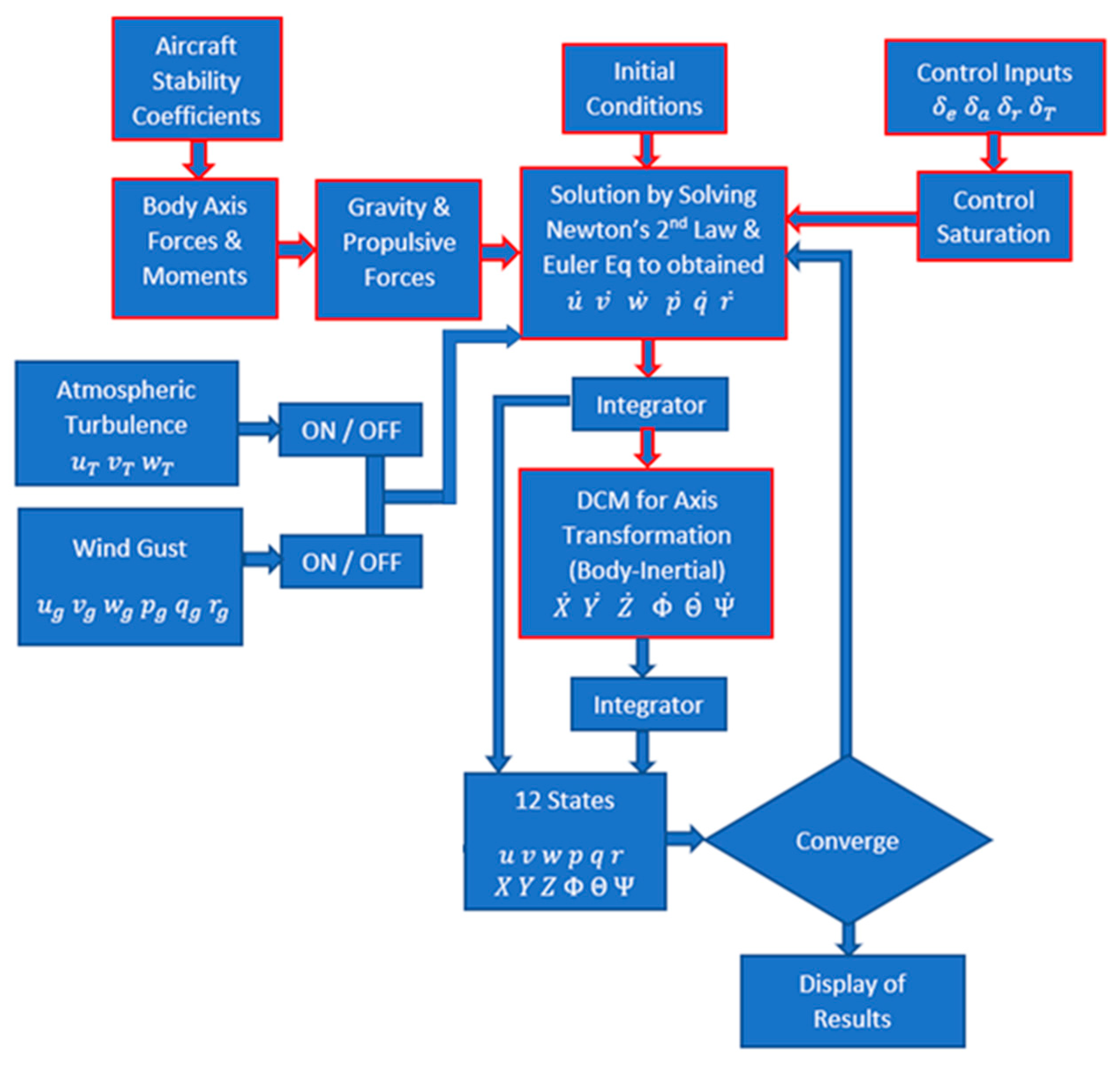
The flow chart for capturing the non-linear dynamics with controls and atmospheric inputs is shown in Figure 3. Stability coefficients were converted into dimensional forces and moments in the body axis; after adding gravitational and propulsive forces, the 6-DOF equations were solved using the initial conditions and control inputs. The rates obtained are converted into six state variables using an integrator. The remaining six state variables were calculated using a directional cosine matrix (DCM), followed by an integrator. Once the turbulence and wind gust blocks are connected, the linear and angular velocities generated by these blocks are added to the state velocities, with the cycle being repeated for the next time step. An inbuilt explicit solver was used for the solution of the 6-DOF equations in an iterative manner for each time step.
For the acquisition of Boeing 747-200 aerodynamics and geometric data, various studies [60,61] were consulted for the formulation of the non-linear model. Aerodynamic forces and moments were linearized into two sets of equations (i.e., longitudinal and lateral) and were embedded into the nonlinear models. Input and output state variables were used in the flow chart and are documented in Table 1. Data for approach and cruise conditions are presented in Table 2, with flight parameters presented in Table 3.

3.1. Schematic of UDF

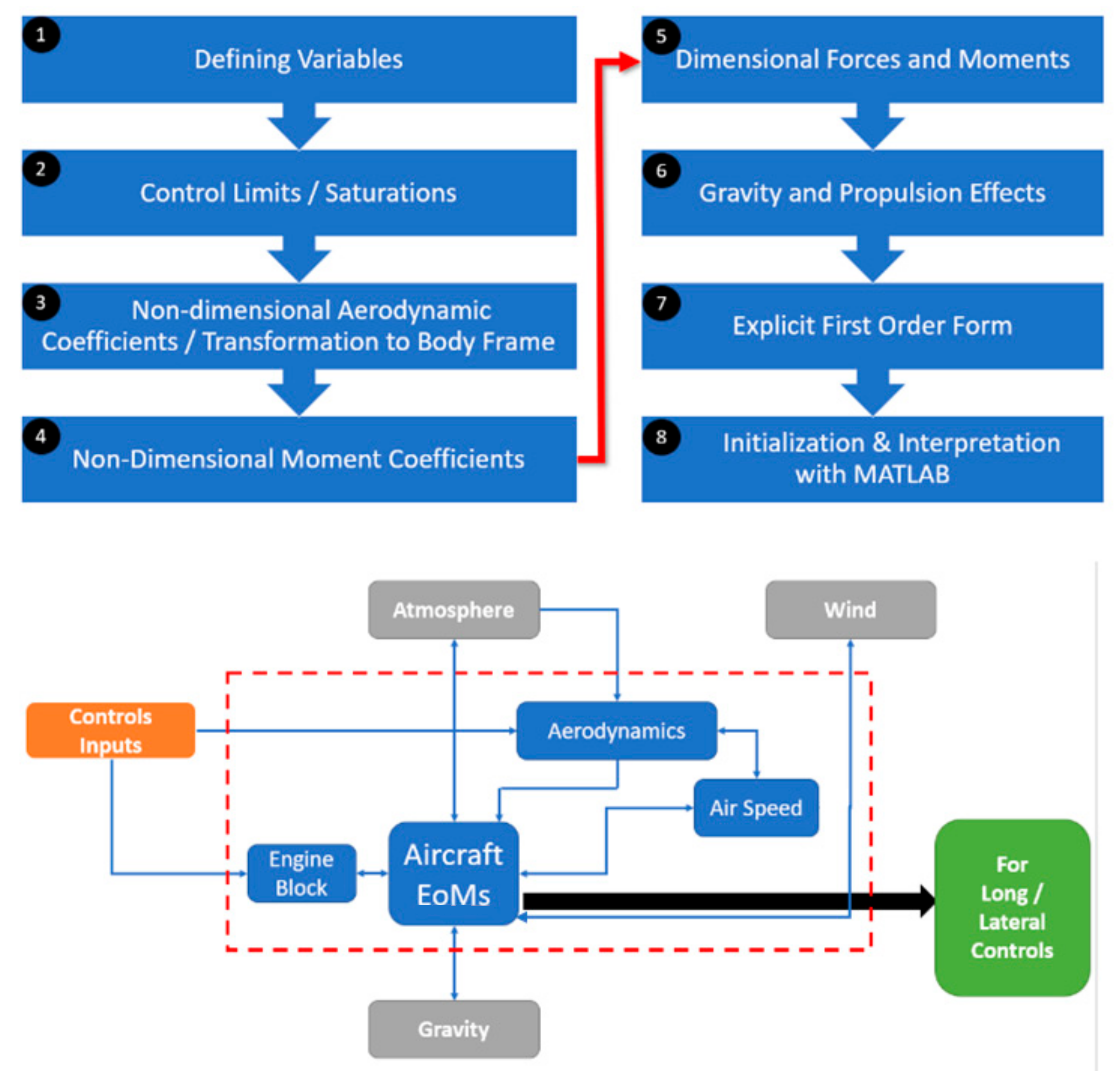
Instead of using built-in Simulink blocks for modeling the 6-DOF non-linear dynamic, a user-defined function (UDF) was developed in order to provide design freedom for the implementation of various design concepts; the UDF structure is outlined in Figure 4. It started with the definition of the variables to be used in the UDF and was followed by documenting the control limits/saturation. In the next step, data are gathered were arranged to form the non-dimensional aerodynamics force coefficients. These forces were computed along with the relevant velocity or stability axis; then, they were transformed into the body frame.
In the fifth step, the non-dimensional forces and moment coefficients in the body frame were transformed into the dimensional form using the reference parameters; the effects of gravity and propulsive forces were computed separately. Once all the forces and moments (including gravity and propulsive) were accounted for, these terms were represented in the form of explicit first-order equations (ref. Equation (9)). In the last step, the UDF was initialized using the initial conditions; it was interpreted into the Simulink canvas using the interpreted MATLAB function block. A schematic of the UDF Block and the inputs are shown in Figure 4; the elements bounded by the red-dashed rectangle are the elements of the UDF and the elements outside the rectangle are the Simulink Block Sets used for generating various input conditions for the UDF. The UDF can generate up to a maximum of 12 output states (including three linear accelerations, three angular accelerations, three Euler’s angle rates, and three inertial frame velocities). However, the output can be restricted to a lower number of desired outputs by commenting out the remainder of the outputs.

3.2. Axis System

As there are two axes’ systems involved in the calculation, it is better to define the axes system for each coordinate system; this will provide a means to better interpret the results. The body axis coordinate system is fixed to the location of the aircraft CG and follows conventional directions (i.e., positive Xb axis is pointing toward the nose of the aircraft, positive Yb axis toward the tip of the right wing, and positive Zb axis pointing downward from the CG point). Finally, in the inertial frame or earth fixed axes system, the positive Xe axis is pointing toward the north, positive Ye axis toward the east, and positive Ze axis pointing in the upward direction.

3.3. Designing of Simulink Canvas

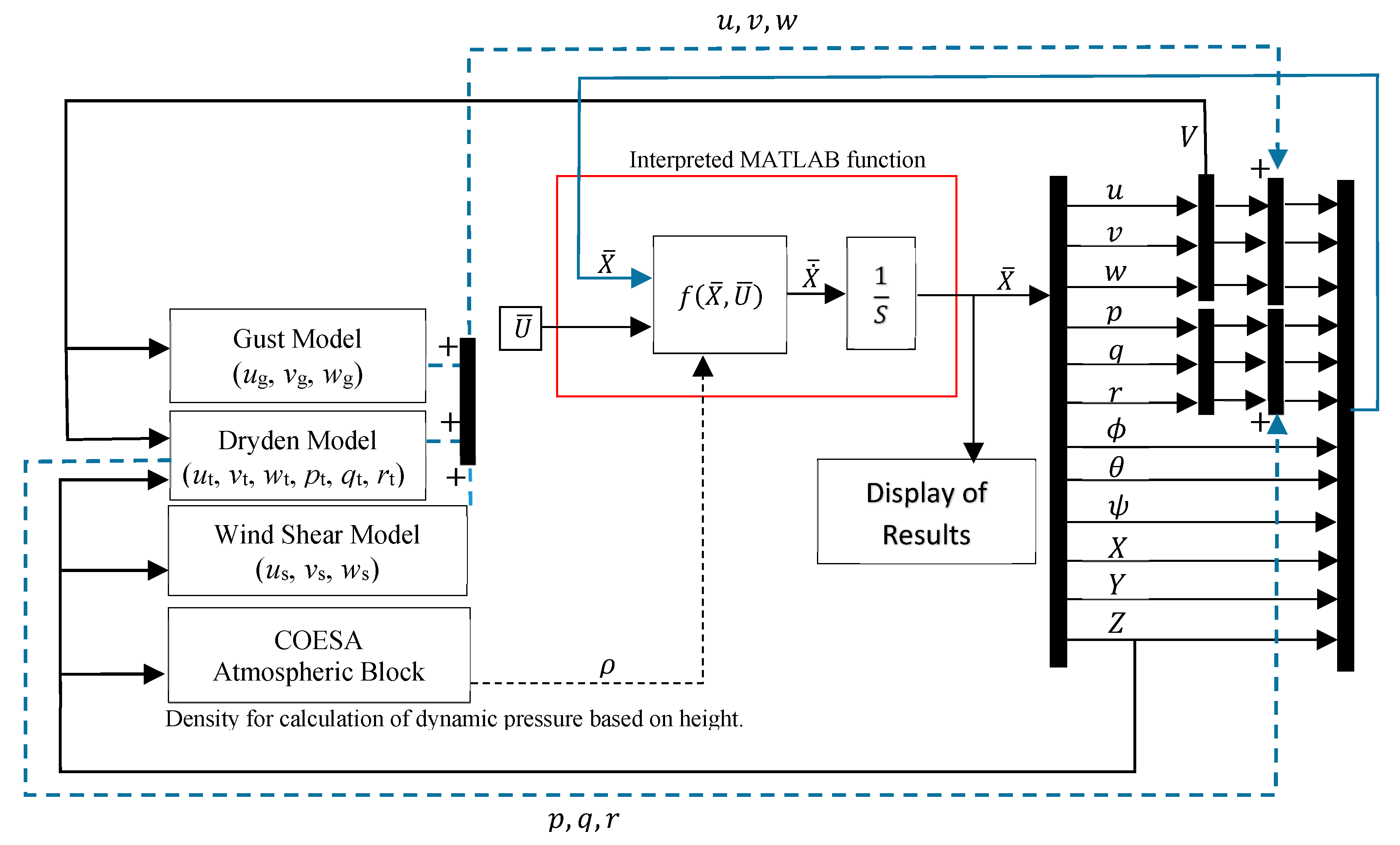
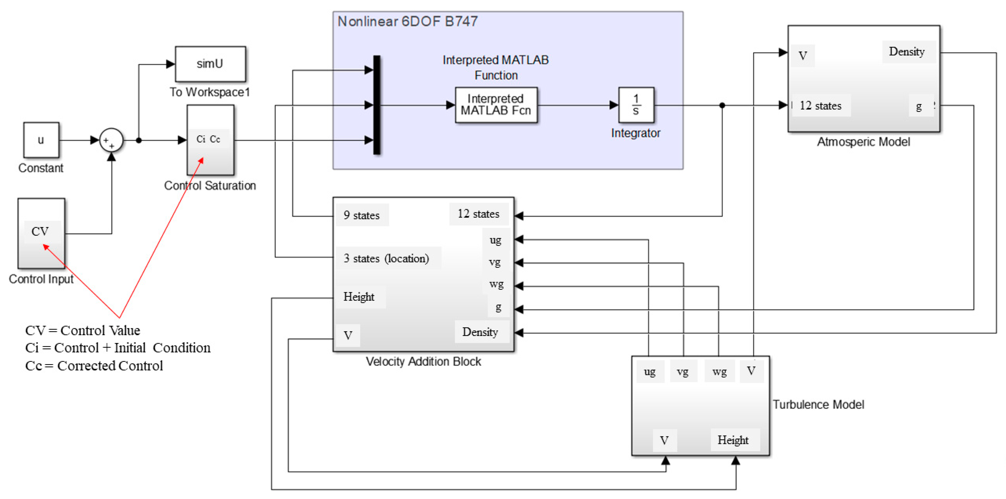
After the UDF (Simulink canvas, see Figure 5) was designed for the implementation of the non-linear dynamic model, the UDF was interpreted in the MATLAB function block (shown in red in Figure 4) and was linked to the control input/saturation block. Atmosphere, wind turbulence, and velocity addition blocks were annexed with the MATLAB function block in order to generate real-time atmospheric conditions and wind velocities.
The COESA atmospheric model, WGS84 gravity model, and dynamic pressure blocks were combined in a single “atmosphere” block; this block had the altitude and velocity information that could generate the real-time density, dynamic pressure, and gravity parameters; the “wind turbulence” block set comprises the Dryden wind turbulence, wind shear, and wind gust blocks. The output of the wind turbulence block is the set of linear and angular wind velocities based on the altitude. These velocities are combined with the velocities obtained from the UDF block from the “velocity addition” block and routed back to the UDF block (along with control inputs for subsequent iterations).
The output of the UDF block is in terms of rates and can be converted to state variables using the integrator. Initial conditions are provided separately through the *.M script file for integration. Whenever the canvas is run, the interpreted block will call the UDF to solve the non-linear equations (based on control inputs and wind conditions). The solver setting was set to auto-solver (with a tolerance of 1 × 10⁻³ and variable step size), with an auto adjustment for the solution of the 6-DOF equations.
It is important to note that horizontal and vertical wind shear were generated using the defined block sets; however, for the generation of microbursts, additional changes were incorporated in the UDF for simulating the microburst profiles. As the Simulink block set for microburst was not available, the complete scenario was generated through the coded script. Based on the physics of the microburst, velocity components were generated as a function of time and were added through the aerodynamic block set.

3.4. Validation of Non-Linear Model

  • Validation using the Boeing 747-200: A state–space model was built using the values for the Boeing 747-200 taken from [61]. The characteristic equation was formulated using frequencies and the damping ratio calculated for Phugoid and short periods. The frequencies were found to be in agreement with the frequencies captured during UDF simulations for the control input, thus validating the UDF accuracy (see Table 4). Moreover, the trim conditions calculated for the approach and cruise conditions were found to be in agreement with the data published in [61] and provide further authentication of the accuracy of the non-linear model. The time history plots obtained from the present canvas also predicted the same trim conditions under the same operating conditions as those mentioned in [61] and had a maximum error of 5.1%.
2.
Validation using a Civil Airplane Model (RCAM): Further validation of the designed canvas was performed using RCAM (an open-source model from the Group of Aeronautical Research and Technology in Europe (GARTEUR) [62,63]). The non-linear UDF was updated with the RCAM model parameters; simulation results were found to be in agreement with the RCAM results available in [62]; this further validated the functionality and structure canvas for computing non-linear flight dynamics. After successful validation, simulations were carried out for two flight conditions: (i) at sea level and (ii) at 40,000 feet cruise flight conditions; the results are discussed in the subsequent sections.

4. Aircraft Trim Conditions and Control Response

After the validation of the canvas, the canvas was tested for different trim conditions and the response of the aircraft to different control inputs. Both the longitudinal and lateral controls were actuated for impulse and step inputs to simulate the response of the aircraft. The complete simulation plots are presented in Appendix B.

4.1. Sea Level Flight Condition

(1)
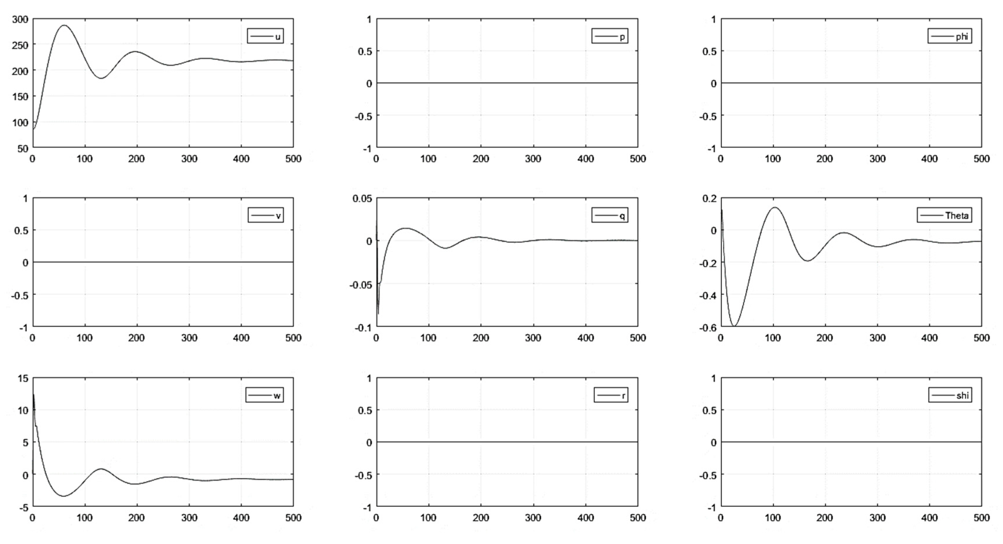
Without control inputs: The model was updated using the sea level coefficients and was subjected to various initial conditions. The initial conditions acted as a disturbance in the system and the aircraft free response was captured; Figure 6 shows the variation in the longitudinal variables. The aircraft entered phugoid mode, which died out subsequently and the aircraft achieved trim conditions. The trim longitudinal velocity achieved was approximately 225 m/s (documented value of 221 m/s in literature [63]).
(2)
With elevator control input: In order to evaluate the free response, a 5° impulse elevator input was initiated (acting as a longitudinal disturbance); the aircraft entered a long-period oscillation that subsequently died out; then, the aircraft returned to its trimmed state (see Figure A7 of Appendix B).
In order to evaluate the forced response, a 5° step elevator input was initiated; the aircraft went entered oscillatory behavior, which subsequently died out and achieved a new trim condition under the influence of the constant elevator input. The response agreed with the theoretical knowledge regarding the variation trends in the longitudinal set of parameters (see Figure 7).
(3)
With lateral control inputs: Under the influence of lateral controls (aileron and rudder impulse inputs), the longitudinal states remained unaffected; the lateral states depicted short-period oscillation as a response to lateral control deflection, which quickly died out and regained its original position. The bank angle ϕ recovered its original zero position; however, the yaw angle ψ reached a new trim position (as expected from theoretical knowledge—see Figure A9 and Figure A10 of Appendix B).
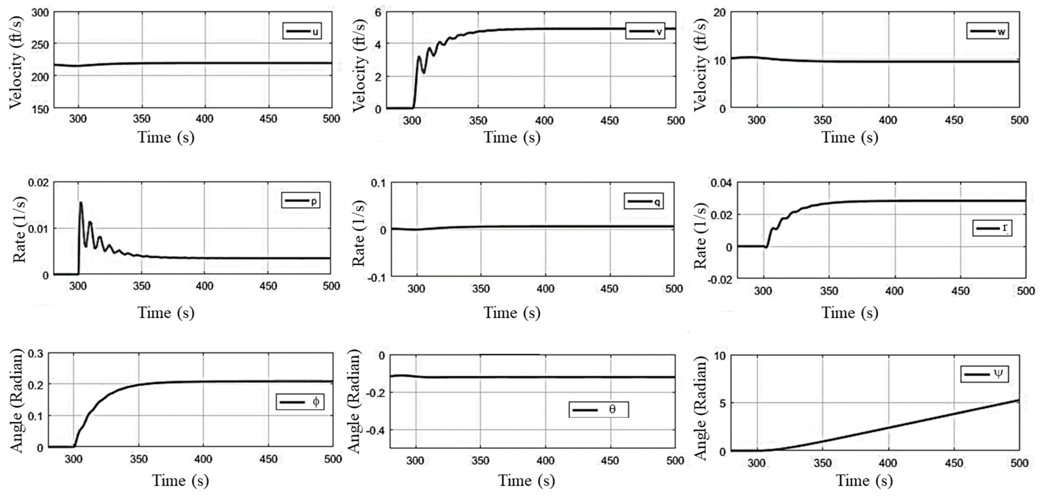
For the forced response, the aileron step input was generated, with the aircraft exhibiting a short-period oscillation, reaching a new trim state under the influence of a constant lateral input (see Figure 8). The aircraft steady-state roll rate can be seen in Figure 8 for a 5° aileron step input.

4.2. Cruise Flight Condition

The model was updated with the cruise parameters; simulations were run in order to capture aircraft behavior under cruise flight conditions. The aircraft showed similar behavior to impulse and step control inputs for both the longitudinal and lateral modes that were found for sea level.

5. Aircraft Response to Wind Turbulence and Wind Shear

(1)
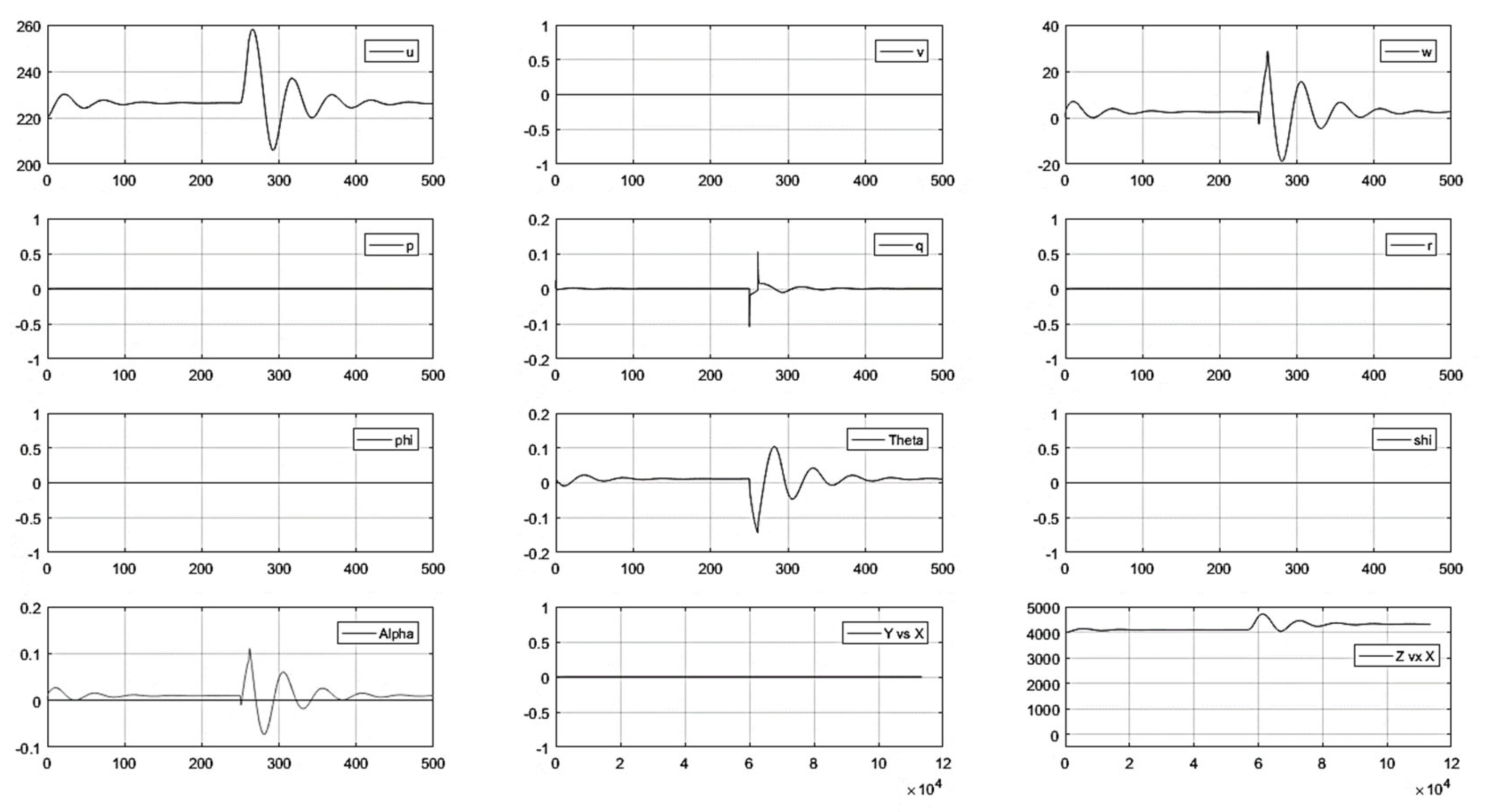
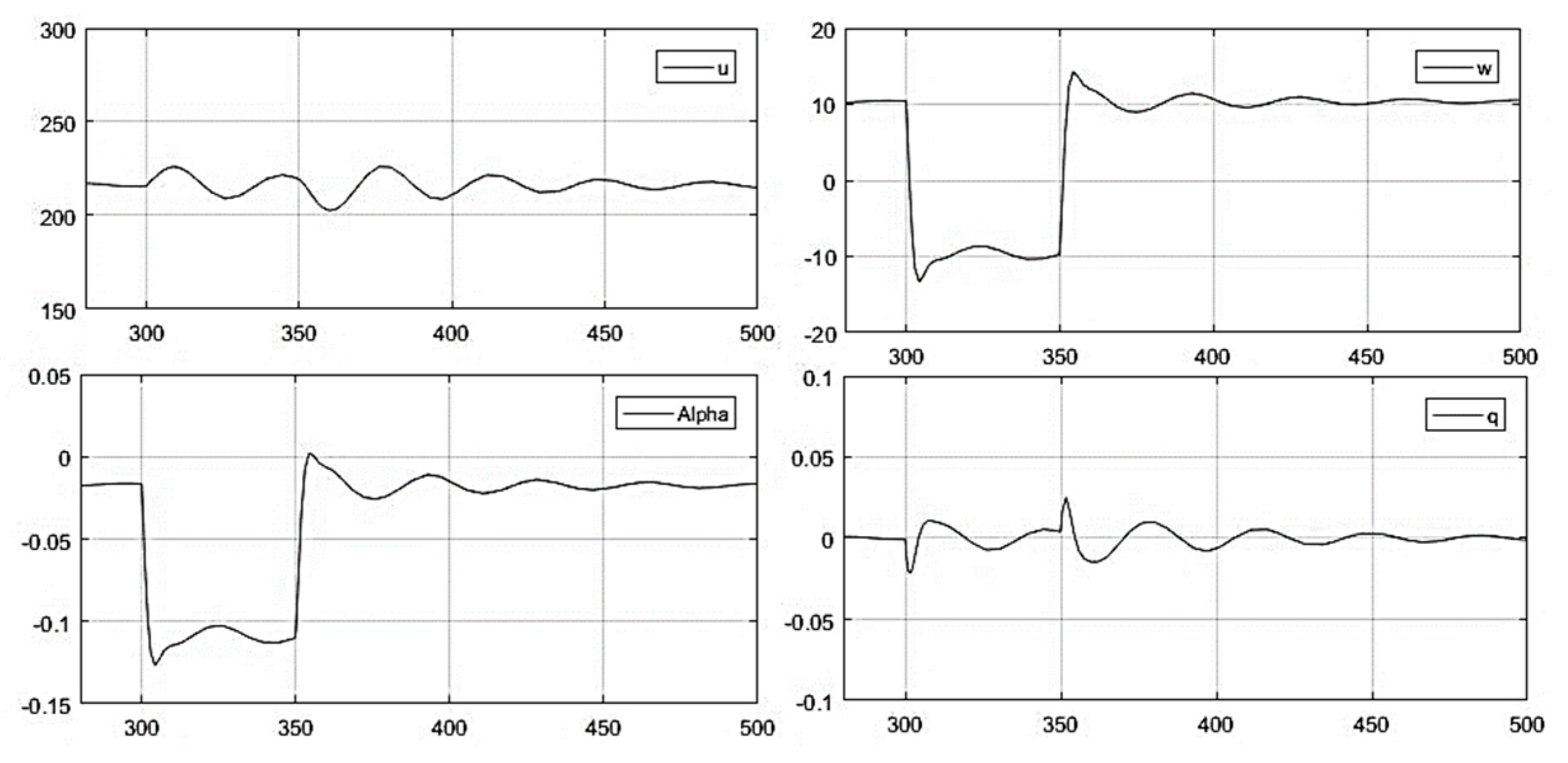
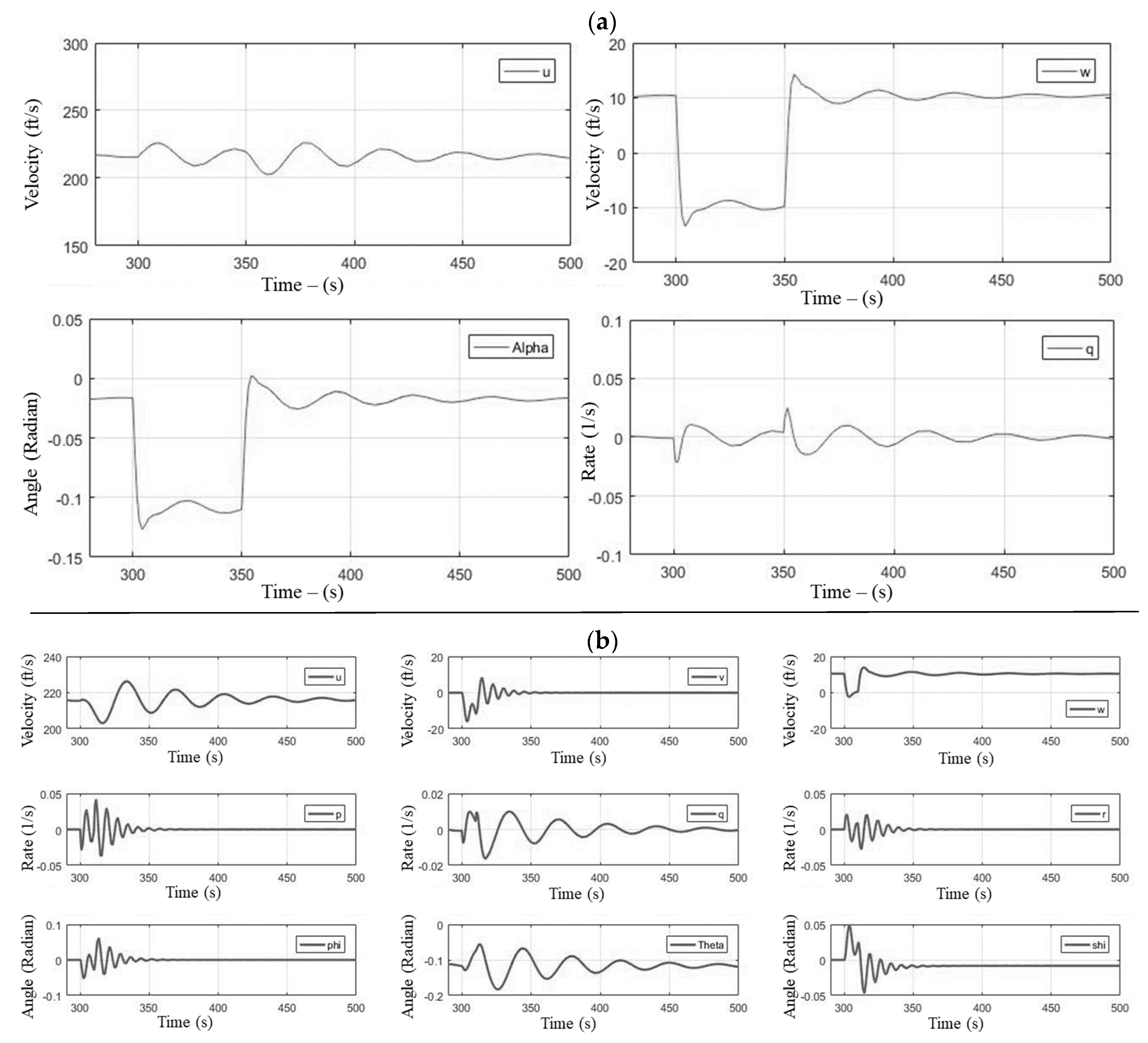
Wind gust. In order to check the aircraft response to a wind gust, a constant velocity vertical wind gust of 20 ft/s was generated at sea level flight conditions for 50 s using the Simulink wind shear and gust blocks. As expected, the aircraft angle of attack was disturbed for the period of wind gust (see Figure 9a); once the gust was removed, the aircraft regained its trim conditions. The aircraft response to a 3D gust of 10 ft/s in all directions was also simulated; the response of the aircraft to the 3D gust is presented in Figure 9b. All the state variables were disturbed from its trim conditions for the period of gust, and once the gust was removed, the aircraft regained position.
(2)
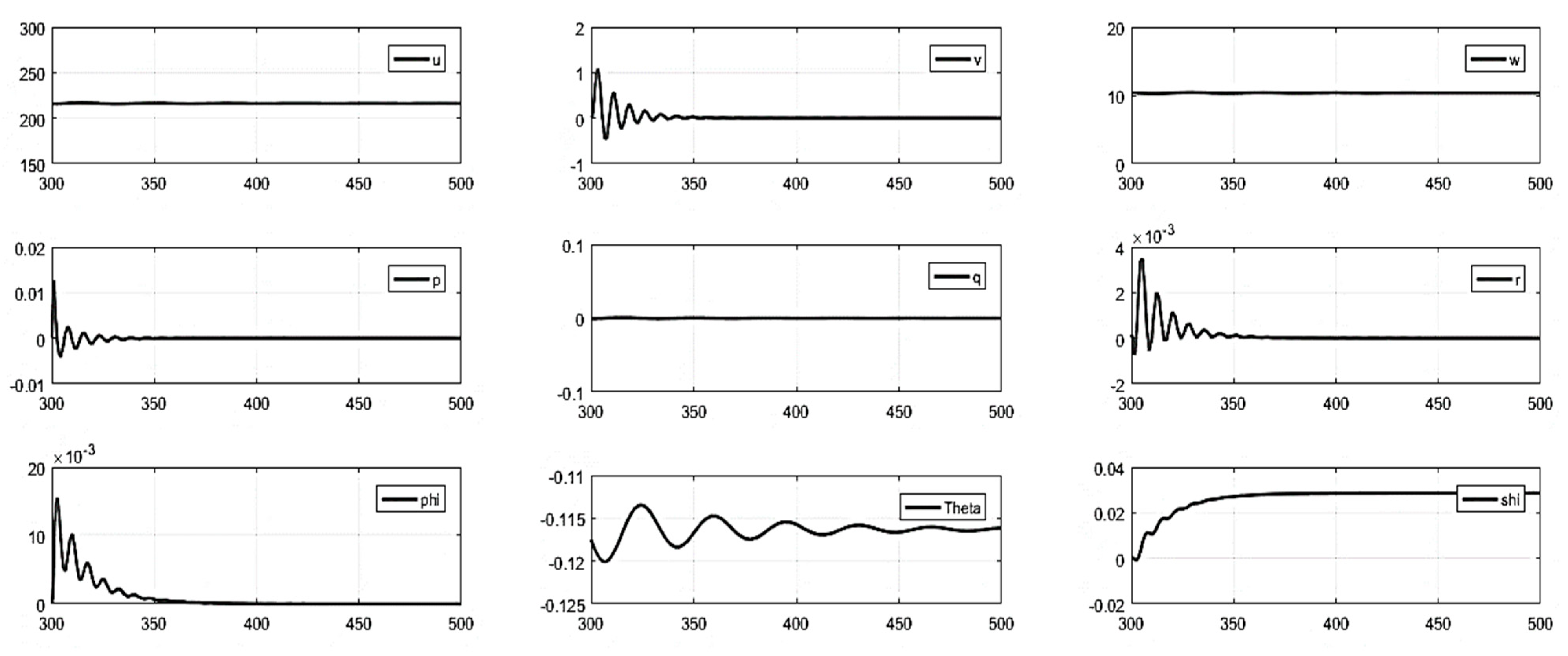
Atmospheric turbulence. In order to analyze the behavior of the aircraft for atmospheric turbulence, the turbulence block was used during the simulations. As wind turbulence is a three-dimensional phenomenon, all the modes are affected. However, the random fluctuations were small in amplitude and continued for the entire duration of the simulation; therefore, all the modes kept fluctuating about their free-response behavior.
(3)
Atmospheric conditions at landing. As the landing approach is the most critical phase of flight and sudden changes in wind profile in the proximity of the ground have catastrophic effects on flight safety; therefore, a detailed analysis with a variety of wind gust profiles was conducted to ascertain the free response of the aircraft during landing conditions.
(i)
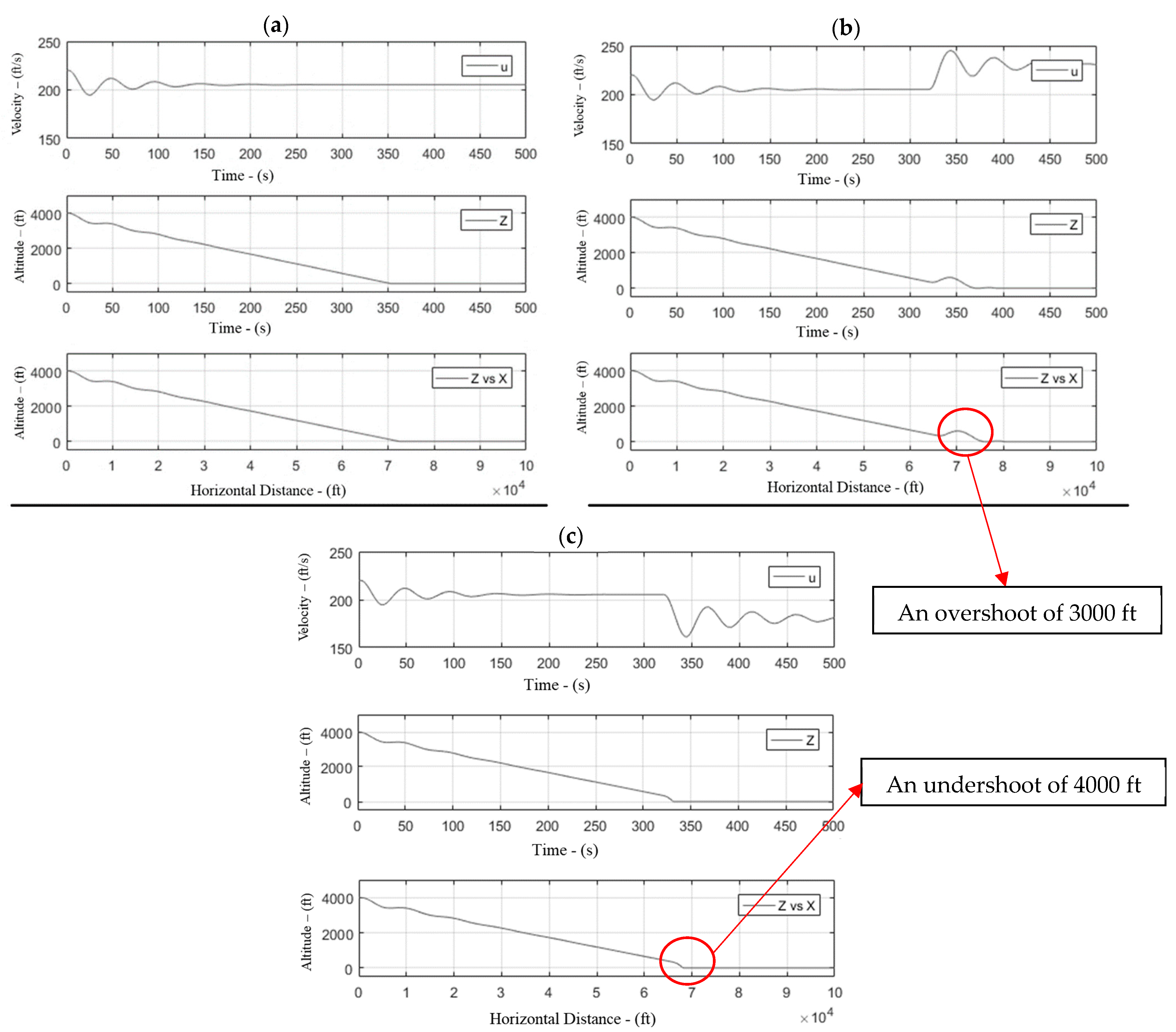
Landing in headwind and tailwind conditions. When considering an aircraft on a standard 3° glide slope that was subjected to 25 ft/s headwinds (see Figure 10), the effective speed of the aircraft increased due to headwind and generated more lift. As a result, the aircraft gained height and was disturbed from its preset glide course. The aircraft experienced an overshoot of approximately 3000 ft from the touchdown point. Similarly, an undershoot of approximately 4000 ft was recorded for a 25 ft/s tailwind condition due to the reduction in the effective forward speed. The undershoot and overshoot were increased to approximately 6000 ft once the wind velocity was increased to 30 ft/s.
(ii)
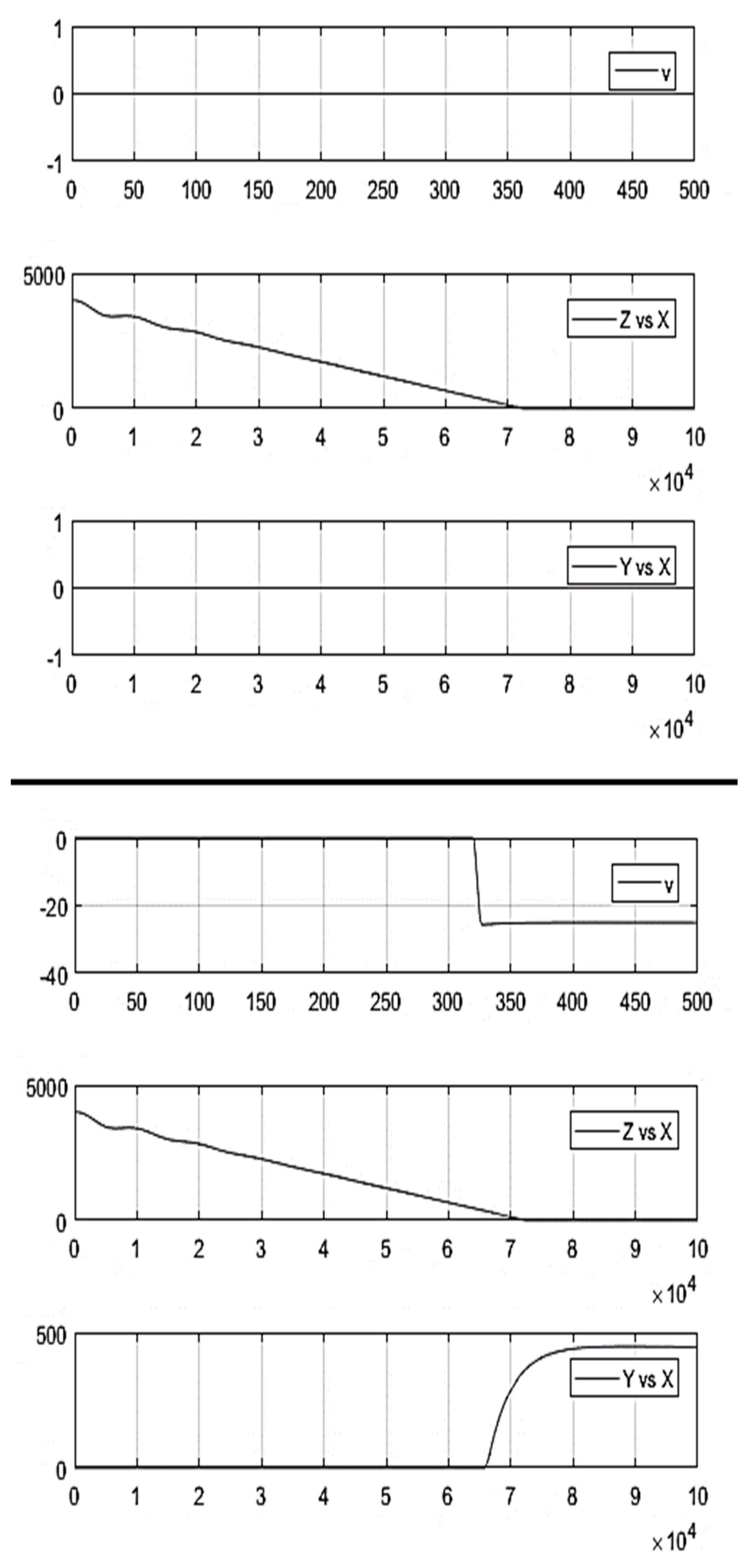
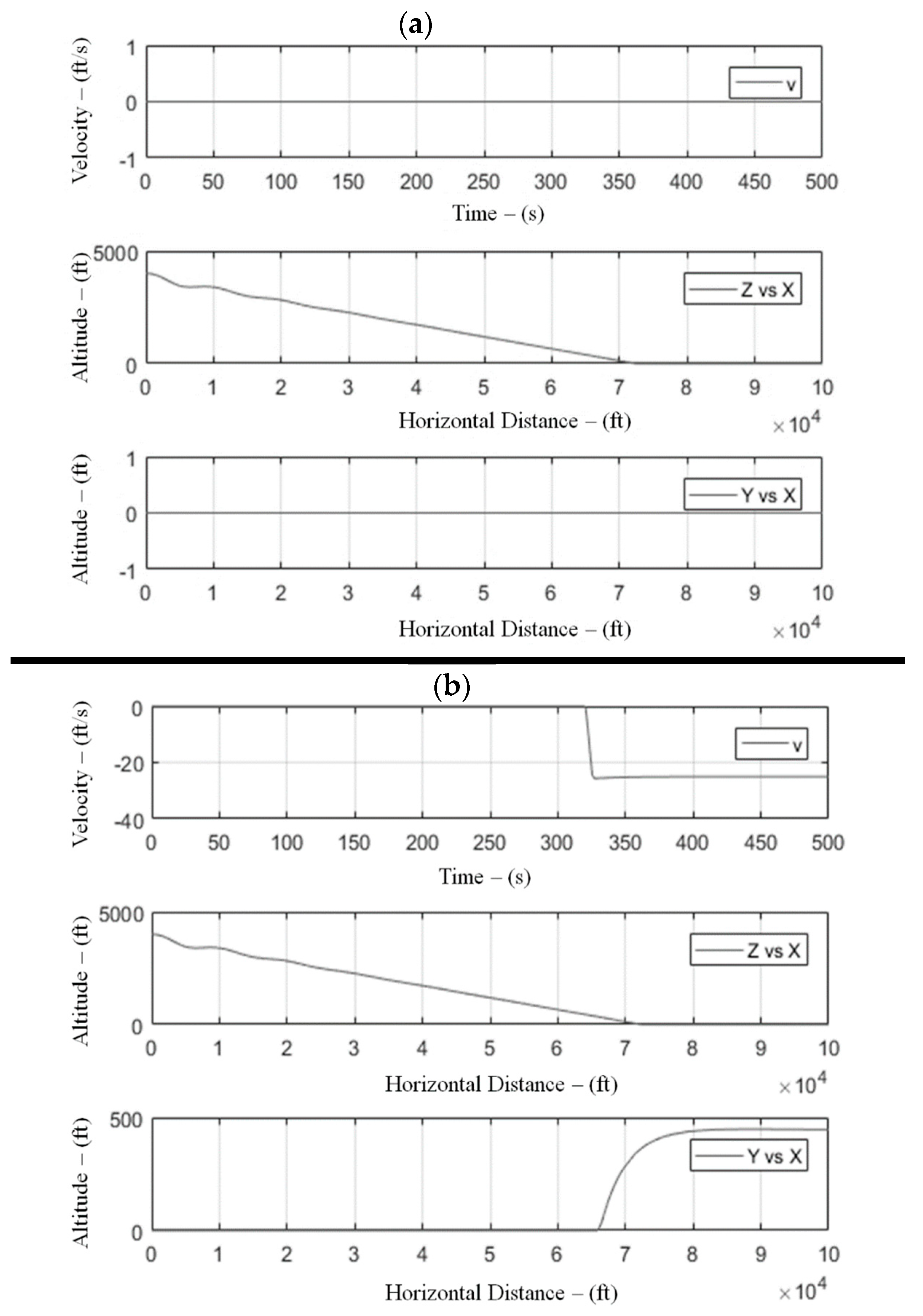
Landing in crosswind conditions. A case of a 25 ft/s 90° crosswind condition was also simulated; as expected, the aircraft started drifting in the direction of the crosswind. Under the simulated conditions, the aircraft became offset from its landing approach by approximately 450 ft (see Figure 11), with the glide slope and touchdown point being negligibly affected. Due to inherent coupling, the roll and yaw rates along with the variation in roll and yaw angle were observed. Once the crosswind conditions were reduced to 10 ft/s, an offset was reduced to 180 ft from the initial course.
(iii)
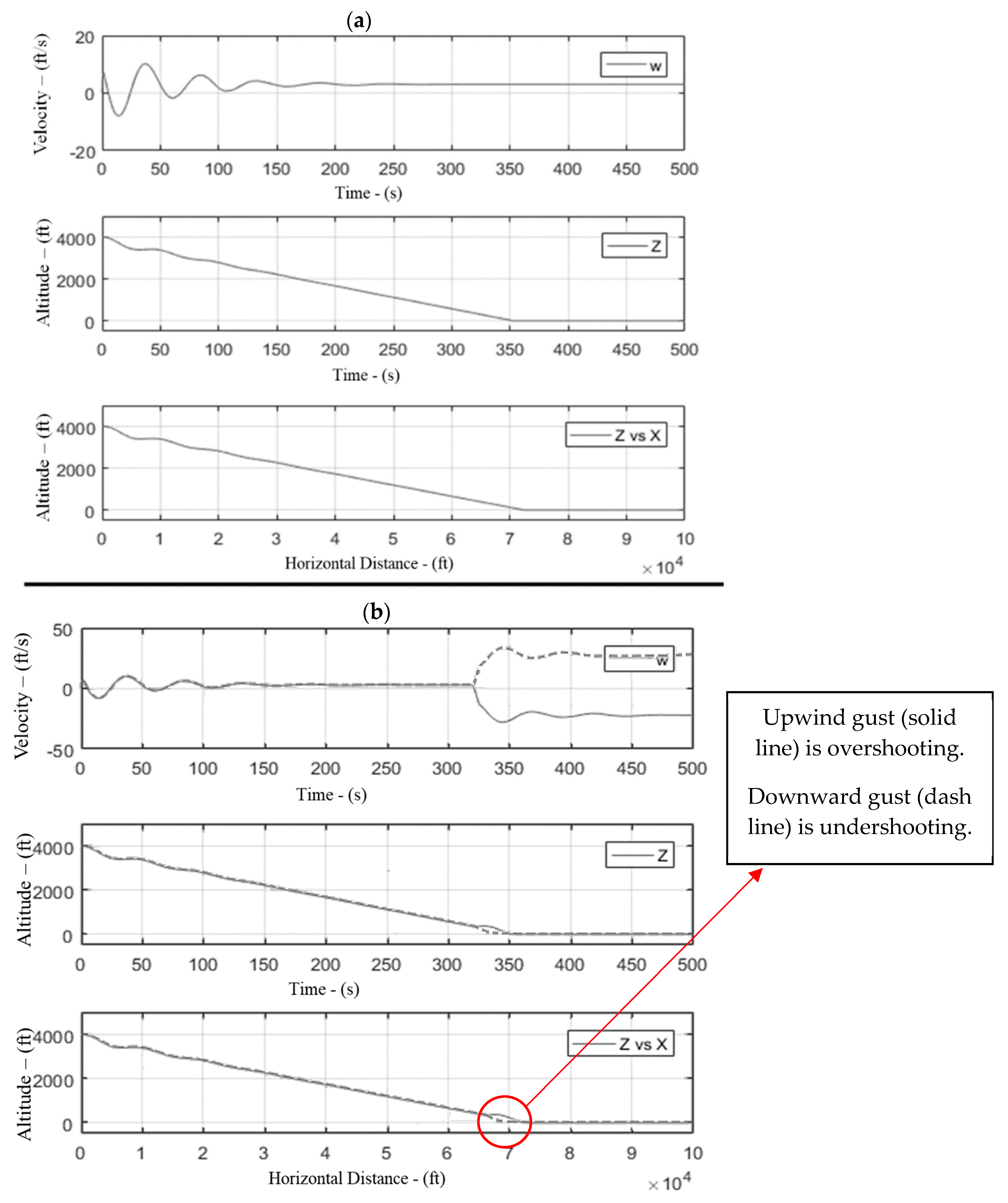
Landing in vertical wind shear conditions. Vertical wind shear simulations were also conducted for a wind velocity of 25 ft/s. During an upward gust condition, the effective angle of attack increased for the aircraft, thus increasing the overall lift of the aircraft. The aircraft momentarily gained height, departing from its preset 3° glide slope before diving again to a glide slope of approximately 10° and overshooting the touchdown point by a couple of hundred feet (see Figure 12). In the case of a downward gust condition of 25 ft/s, the aircraft’s angle of attack decreased, and this put the aircraft into a steep glide slope of approximately 11~12° and undershot the touchdown point by approximately 4000 ft.
(iv)
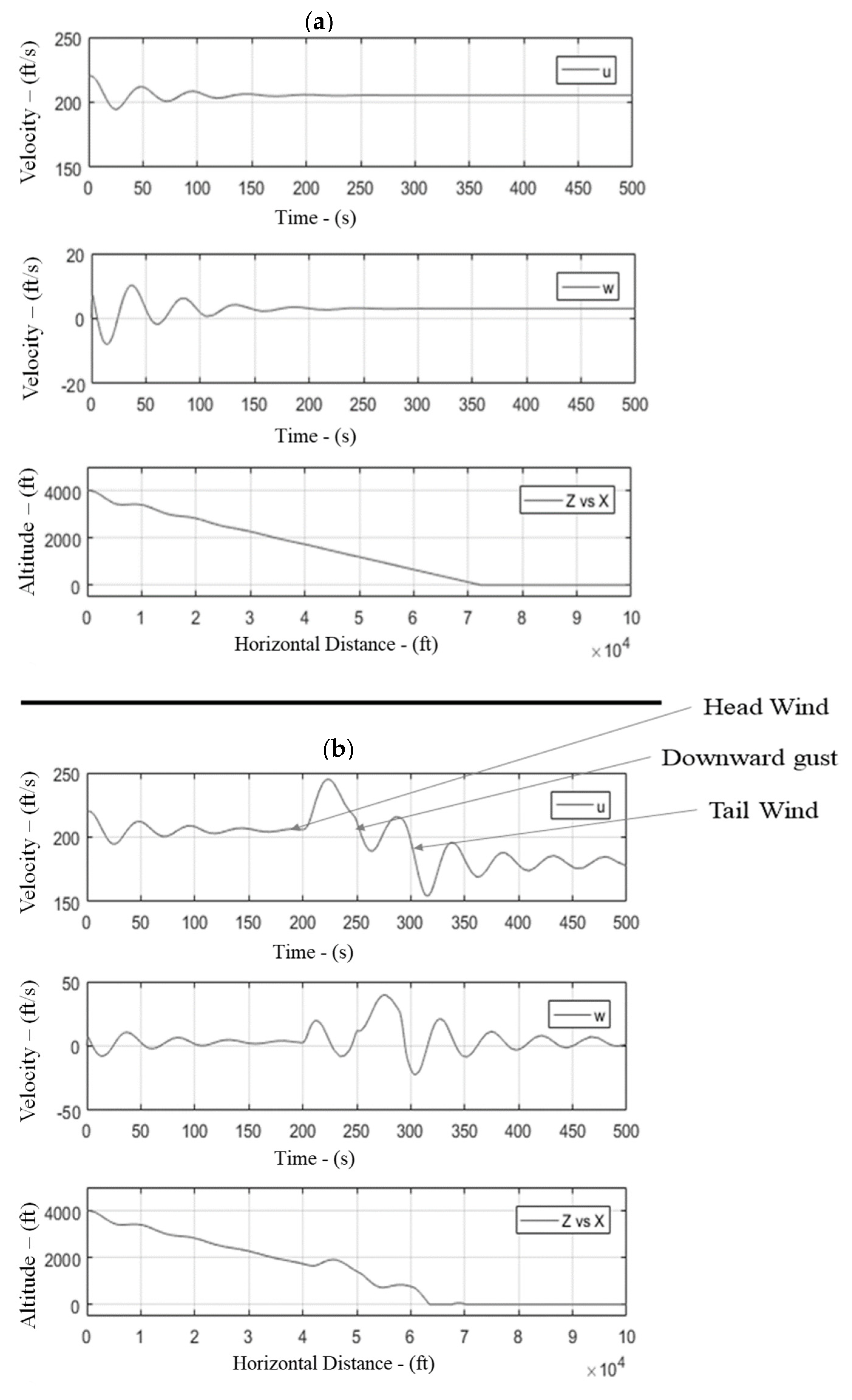
Landing in microburst conditions. A microburst with a maximum velocity of 25 ft/s was also simulated. As the physical spread of the velocity profile was higher, the burst simulations were started at 32,000 ft short of the actual touch-down point. In the first phase, a headwind of 25 ft/s was built and sustained for 10,000 ft and then transitioned into a sustained downwind of 25 ft/s for another 10,000 ft. In the last phase, the downwind was transitioned into a tailwind of 25 ft/s, which continued until touchdown. As expected, initially, the aircraft gained height in the headwind condition due to an increase in the effective speed (departing from its 3° glide course), followed by a sharp dip under the influence of the sustained downwind. The aircraft momentarily leveled off while transitioning from a downwind condition to a tailwind condition; it then glided down at a sharp angle of ~14.5° under the influence of tailwind (as the aircraft’s forward speed was reduced). Aircraft touchdown was approximately 8000 ft short of the actual touchdown point (see Figure 13); additionally, the descent rate was also high. It was the high glide slope angles and higher descent rate that led to aircraft crashes while encountering microbursts short of the runway. This dangerous phenomenon associated with aircraft crashes encountering microbursts during the approach was successfully simulated and analyzed.

6. Conclusions

This study was a flight dynamic study of the Boeing 747-200; it was carried out with atmospheric turbulence, wind gusts, and microburst conditions. A non-linear 6-DOF model was created with the Simulink canvas and integrated with built-in MATLAB block sets; a UDF for generating atmospheric conditions was also utilized. The canvas was validated via a comparison of the result with published data for the Boeing 747-200 for various cruise and take-off conditions. The trim conditions, time period, and frequency response were found to be in agreement with the published data for a maximum error of 5%. Results were obtained using this canvas for aircraft flight characteristics and new trim states for free and forced responses. The aircraft response was found to be in agreement with published data for all three control inputs. For the atmospheric turbulence case, the aircraft was found to remain stable and oscillate about its trim state. Various cases of wind gusts were simulated during the landing approach to ascertain aircraft variation in touch-down points. It was found that in the headwind case, the aircraft overshot the touchdown point because of an increase in lift due to an increase in relative wind. Furthermore, for the tailwind case, the aircraft response was opposite to the headwind case, with an increase in glide slope from 3° to 10°. Additionally, a microburst case was presented that produced an even higher degree of glide slope during landing (increased to 14°). During the initial phase of the microburst condition, the aircraft gained altitude under headwind, followed by a sharp decrease in altitude under the vertical component of wind. In the final phase of the microburst, the aircraft was found to lose lift and underwent a sudden decrease in altitude. Finally, it was concluded that the proposed Simulink canvas could be used as a tool for flight dynamic analysis of an aircraft during landing patterns for several flight and atmospheric conditions.

7. Future Work

Based on the data available for the Boeing 747-200, the canvas was formulated with static ground effects. The authors plan to validate and modify the canvas for dynamic ground effects subject to the availability of aircraft data. Additionally, the authors plan to acquire actual quick access recorder (QAR) gust data for real-life aircraft and integrate them with the developed canvas for the validation of the aircraft response.

Author Contributions

Conceptualization, S.I.A.S. and K.M.; Methodology, T.A.S., K.M. and M.N.M.Q.; Validation, K.M. and T.A.S.; Formal analysis, K.M. and S.I.A.S.; Investigation, K.M., S.I.A.S. and T.A.S.; Resources, T.A.S., M.N.M.Q., T.A.K. and D.K.; Data curation, K.M. and S.I.A.S.; Writing—original draft, K.M., T.A.S. and T.A.K.; Writing—review & editing, T.A.K. and D.K. All authors have read and agreed to the published version of the manuscript.

Funding

This research received no external funding. And The APC was funded by Prof. David Kukulka.

Data Availability Statement

No new data were created or analyzed in this study. Data sharing is not applicable to this article.

Conflicts of Interest

The authors declare no conflict of interest.

Nomenclature

IInertia tensor
Ix, Iy, IzMoment of inertia about axis (rotational inertia that resists change in the rotational velocity of an object on its axis
Ixz, Iyz, IxyProduct of inertia (feature of an object that describes an imbalance relative to a defined set of coordinate axes)
L , M, NMoments about x, y, and z-axes in a body frame, respectively. L corresponds to rolling, M corresponds to pitching, and N corresponds to yawing moment of the aircraft
u , v , w Velocity components about x, y, and z-axes in a body frame
u ˙ , v ˙ , w ˙ Translational accelerations about x, y, and z-axes in a body frame
p , q , r Angular velocities about x, y, and z-axes in a body frame
p ˙ , q ˙ , r ˙ Rotational accelerations about x, y, and z-axes in a body frame
ϕ , θ , ψ Euler angles of aircraft about x, y, and z-axes of inertial frame
ϕ ˙ , θ ˙ , ψ ˙ Rate of change of Euler angles about x, y, and z-axes of inertial frame
X , Y , Z Position coordinates of the aircraft with respect to inertial frame
d X d t , d Y d t , d Z d t Translational velocities of the aircraft with respect to inertial frame
R b / i Direction cosines for transformation of vectors from body frame to inertial frame

Appendix A

Formulation of Equations of Motion (EoMs):
  • Assumption. While formulating EoMs for aircraft (747-200), the following assumptions were made:
    (a)
    The aircraft is a rigid body.
    (b)
    The Earth is taken as an inertial frame—stationary flat surface.
  • Formulation of non-linear EoMs: According to Newton’s second law, the motion of a rigid body in an inertial frame is governed by Equation (A1).
F ¯ = d d t i m V ¯ = m d d t i V ¯ = m V ¯ ˙ i
If the body is rotating with respect to the inertial frame, it is difficult to compute the derivative directly. Therefore, the calculations were performed for a body frame axis attached to the body itself and then transferred to inertial frame. For a body frame rotating with ω ¯ b / i with respect to the inertial frame, the transformation equation is presented in Equation (A2). For simplicity, we can write ω ¯ b / i   a s   ω ¯ in the equations.
V ¯ ˙ i = V ¯ ˙ b + ω ¯ × V ¯ b
Inserting the value of V ¯ ˙ i from Equation (A2) into Equation (A1), we obtain
F ¯ = m V ˙ b + ω ¯ × V ¯ b
whereas ω ¯ × V ¯ b = i ^ j ^ k ^ p q r u v w = q w r v i ^ p w r u j ^ + p v q u k ^ .
So,
F _ x = m u ˙ + q w r v F _ y = m v ˙ + r u p w F _ z = m ( w ˙ + p v q u )
Re-arranging Equation (A3), we obtain
V ¯ ˙ b = 1 m F ¯ ω ¯ × V ¯ b     or     u ˙ v ˙ w ˙ = 1 m F ¯ ω ¯ × u v w
Equation (A5) is the transitional velocity equation. Similarly, the summation of moments in an inertial frame is represented in Equation (A6). Again, using the Coriolis equation (A7), we converted the moments into body frame (ref. Equation (A8)). The result is the rotational velocity equation (Equation (A9) and (A10)).
M ¯ = d d t i H ¯ = d d t i I ω ¯
whereas I = I x I x y I x z I y x I y I y z I z x I z y I z = I x 0 I x z 0 I y 0 I z x 0 I z for aircraft with symmetry about the xz-plane, I x y = I y x = I y z = I z y = 0
d d t i I ω ¯ = d d t b I ω ¯ + ω ¯ × I ω ¯
M ¯ = d d t b I ω ¯ + ω ¯ × I ω ¯ = I d d t b ω ¯ + ω ¯ × I ω ¯
M x = I x p ˙ I x z r ˙ + I z I y q r I x z p q M y = I y q ˙ + I x z ( p 2 r 2 ) + ( I x I z ) r p M z = I x z p ˙ + I z r   ˙ + ( I y I x ) p q + I x z r q
Re-arranging Equation (A8), we obtain
d d t b ω ¯ = I 1 M ¯ ω ¯ × I ω ¯     or     p ˙ q ˙ r ˙ = I 1 M ¯ ω ¯ × I ω ¯
Apart from the aerodynamics terms, which, in this paper, are treated as linear, the terms ω ¯ × V ¯ b and ω ¯ × I ω ¯   introduce nonlinearity to EoMs, which is due to the Coriolis effect, while transferring forces and moments from the inertial frame to the rotating body frame. The non-linear terms are shown in a red color in Equations (A4) and (A9).
Apart from the translational and rotational velocities, we are also interested in finding the angular and translational position of the aircraft with respect to the inertial axis. The angular position is derived through Equation (A11) and presented in Equation (A12).
Φ ˙ = H Φ   ω ¯
where H Φ = 1 s i n ϕ t a n θ c o s ϕ t a n θ 0 c o s ϕ s i n ϕ 0 s i n ϕ / c o s θ c o s ϕ / c o s θ
ϕ ˙ θ ˙ ψ ˙ = 1 s i n ϕ t a n θ c o s ϕ t a n θ 0 c o s ϕ s i n ϕ 0 s i n ϕ / c o s θ c o s ϕ / c o s θ p q r
Similarly, the equation for the translational position with respect to the inertial frame is presented in Equation (A14). The transformation is achieved through direction cosines, as shown in Equation (A13).
V ¯ i = R b / i V ¯ b
where R b / i = 1 0 0 0 C ϕ S ϕ 0 S ϕ C ϕ C θ 0 S θ 0 1 0 S θ 0 C θ C ψ S ψ 0 S ψ C ψ 0 0 0 1 = C θ C ψ S ϕ S θ C ψ C ϕ S ψ C ϕ S θ C ψ + S ϕ S ψ C θ S ψ S ϕ S θ S ψ + C ϕ C ψ C ϕ S θ S ψ S ϕ C ψ S θ S θ C θ C ϕ C θ
S ϕ = S i n ϕ ,     S θ = S i n θ ,        S ψ = S i n ψ ,        C ϕ = C o s ϕ ,     C θ = C o s θ ,        C ψ = C o s ψ
d X d t d Y d t d Z d t = C θ C ψ S ϕ S θ C ψ C ϕ S ψ C ϕ S θ C ψ + S ϕ S ψ C θ S ψ S ϕ S θ S ψ + C ϕ C ψ C ϕ S θ S ψ S ϕ C ψ S θ S θ C θ C ϕ C θ u v w
where X, Y, and Z are the position vectors and d X d t , d Y d t , and d Z d t are the velocity components of the aircraft with respect to the inertial frame of reference. Equations (A5), (A10), (A12), and (A14) represent the EoMs for the aircraft and can be easily expressed in state space notation.
3.
Calculation of external forces: To solve Equation (A5), we need to calculate external forces applied on the aircraft. External forces in a body frame are a combination of gravitational force, aerodynamics force, and propulsive forces acting on the aircraft.
F ¯ = F ¯ g + F ¯ e + F ¯ a ( All   forces   are   in   body   frame )
(A)
Gravitational force: In an inertial frame, weight is always acting downward toward the center of the Earth (z-axis of inertial frame) and can be represented as Equation (A16). Gravitational force into the body frame can be calculated using direction cosines as shown in Equation (A17) using Figure A1.
F ¯ g i = 0 0 m g
F ¯ g b = R i / v F ¯ g i = m g S θ C θ S ϕ C θ C ϕ
(B)
Propulsion forces: The Boeing 747-200 has four engines installed on its wings, two on each side (ref. Figure A2). It is assumed that the thrust produced by all the engines is in line with the x-axis of the body frame. Therefore, a simple expression can be used to express the propulsion forces (ref. Equation (A18)). These propulsive forces are throttle-dependent forces and require the throttle position as an input condition.
F ¯ e b = F P 1 + F P 3 + F P 2 + F P 4 0 0
(C)
Aerodynamics Forces: There are three forces acting along the axes of the body frame. These are normal, axial, and side forces. Generally, the forces are captured in the wind axes by definition and need to be transformed back to body axes using a transformation matrix (Ref Equation (A19)). The transformation variables are selected as per Figure A3.
F ¯ a b = F A F S F N = C β S β 0 S β C β 0 0 0 1 C α 0 S α 0 1 0 S α 0 C α F ¯ a w   where   F ¯ a w = D S F L
Therefore, the sum of the external forces is presented in Equation (A20).
F ¯ = m g S θ C θ S ϕ C θ C ϕ + F P 1 + F P 3 + F P 2 + F P 4 0 0 + C β S β 0 S β C β 0 0 0 1 C α 0 S α 0 1 0 S α 0 C α D S F L
4.
Calculation of External Moments: External moments in a body frame are a combination of moments generated by gravitational force, aerodynamics force, and propulsive forces.
M ¯ = M ¯ g + M ¯ e + M ¯ a
As the weight is acting at the center of gravity (CG), gravitational force will not generate any moment about the CG. The propulsive and aerodynamics forces are multiplied with the moment arm (distance of application of force from CG in the respective axes) to obtain the moments. For propulsive forces, the center of the engine was taken as a reference, and for aerodynamics forces, the quarter chord location was taken as a reference for the calculation of moment arms (ref. Equation (A22)).
M ¯ = i = 1 4 x C G x T i F P i y C G y T i F P i z C G z T i F P i + L M N
5.
Calculation of aerodynamics forces: Aerodynamic forces are a function of a lot of variables, which include translational velocities, angular velocities, the rates of change of velocities, control input, etc. The aerodynamic forces and moments can be expressed as a function of all the motion variables; however, only the significant variables are retained, and the rest are neglected.
Note : D = f u , w ,   δ e S F = f ( v , p , r , q , δ r ) L = f ( u , w , w ˙ , q , δ e ) L = f ( v , p , r , δ r , δ a ) M = f ( u , w , w ˙ , q , δ e ) N = f ( v , p , r , δ r , δ a ) δ a = Aileron Input δ e = Elevator Input δ r = Rudder Input δ t 1 = Throttle engine 1 δ t 2 = Throttle engine 2 δ t 3 = Throttle engine 3 δ t 4 = Throttle engine 4
The forces and moments are written in coefficient terms and the coefficient is expanded in terms of dependent variables using the first-order Taylor series.
L = C L Q S     where   C L = C L 0 + c L α α + c L u u V + c L α ˙ α c ˙ 2 V + C L q q c 2 V + c L δ e δ e D = C D Q S     where   C D = C D 0 + c D α α + c D u u V + c D δ e δ e S F = C Y Q S     where   C Y = c Y β β + c Y p p b 2 V + c Y r r b 2 V + c Y δ a δ a + c Y δ r δ r L = C l Q S b     where   C l = C l β β + c L p p b 2 V + c l r r b 2 V + C l δ a δ a + c l δ r δ r M = C m Q S b     where   C m = C m 0 + c m α α + c m u u V + c m α ˙ α c ˙ 2 V + C m q q c 2 V + c m δ e δ e N = C n Q S b     where   C n = c Y β β + c Y p p b 2 V + c Y r r b 2 V + c Y δ a δ a + c Y δ r δ r
where Q = 1 2 ρ V 2 and S = reference area (wing plane form area)
α = tan 1 w u   w u        β = sin 1 v V   w V           V = u 2 + v 2 + w 2        ρ = f ( Z )
Therefore, every term mentioned in the equations (Equation (A24)) is a function of either state variables or control input.
F ¯ = m g S θ C θ S ϕ C θ C ϕ + F P 1 + F P 3 + F P 2 + F P 4 0 0 + C β S β 0 S β C β 0 0 0 1 C α 0 S α 0 1 0 S α 0 C α C D Q S C Y Q S C L Q S
M ¯ = i = 1 4 x C G x T i F P i y C G y T i F P i z C G z T i F P i + C l Q S b C m Q S b C n Q S b
6.
State space representation: Equations (A5), (A10), (A12), and (A14) represent the equations of motion and can be easily represented in a state space notation. For ease, the input conditions X ¯ and U ¯ are placed in a separate column vector as per standard procedures of state space representation (ref. Equation (A27)).
X ˙ ¯ = V ¯ ˙ b ω ˙ ¯ Φ ˙ V ¯ i = u ˙ v ˙ w ˙ p ˙ q ˙ r ˙ ϕ ˙ θ ˙ ψ ˙ d X / d t d Y / d t d Z / d t = 1 m F ¯ ω ¯ × V ¯ b I 1 M ¯ ω ¯ × I ω ¯ H Φ   ω ¯ R b / i V ¯ b = f X ¯ , U ¯ X ¯ + f X ¯ , U ¯ U ¯
where state space = X ¯ = u v w p q r ϕ θ ψ X Y Z = x 1 x 2 x 3 x 4 x 5 x 6 x 7 x 8 x 9 x 10 x 11 x 12 and control input = U ¯ = δ a δ e δ r δ t 1 δ t 2 δ t 3 δ t 4 = U 1 U 2 U 3 U 4 U 5 U 6 U 7
7.
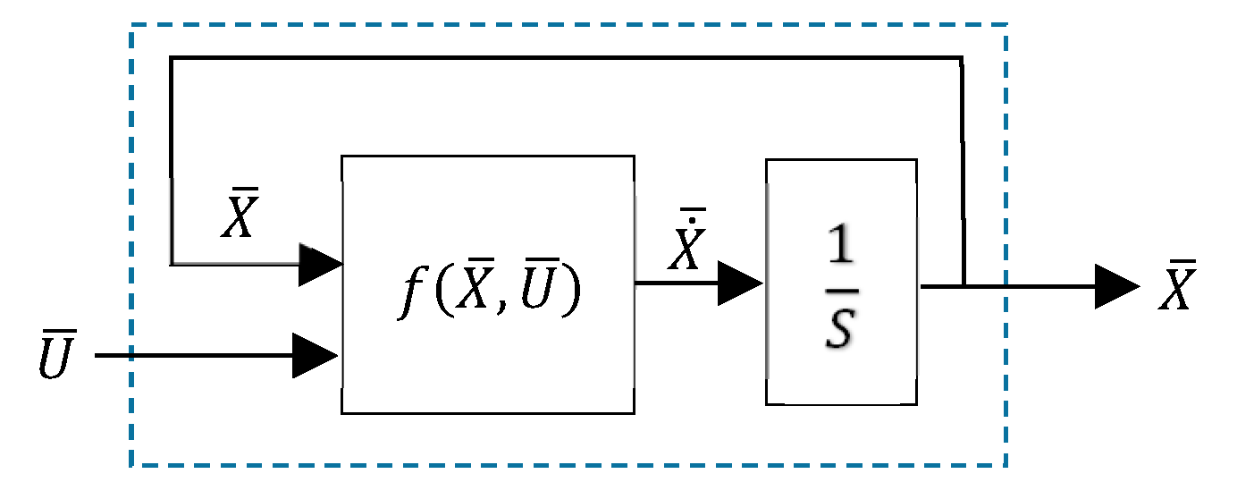
Simulink modeling: The function f X ¯ , U ¯ formulated in Equation A27 was interpreted in a Simulink environment as a user-defined function. The sketch is shown in Figure A4. X ¯ and U ¯ are provided as inputs; the block calculates X ˙ ¯ , which is passed through an integrator to obtain the state space X ¯ . X ¯ is routed again to the block as an input. The cycle continues until convergence is achieved.
8.
Wind turbulence modeling: To introduce the effect of wind turbulence and atmospheric gust/shear, Simulink blocks are separated; the Dryden turbulence model, wind shear, and wind gust were incorporated into the canvas. The schematic of the improved canvas is shown in Figure A5. The density variation with height was captured through the COESA atmospheric block. The linear and angular wind velocities were summed up with the velocities obtained from the interpreted MATLAB function and rerouted to the interpreted MATLAB function block for subsequent iteration until the solution is converged.
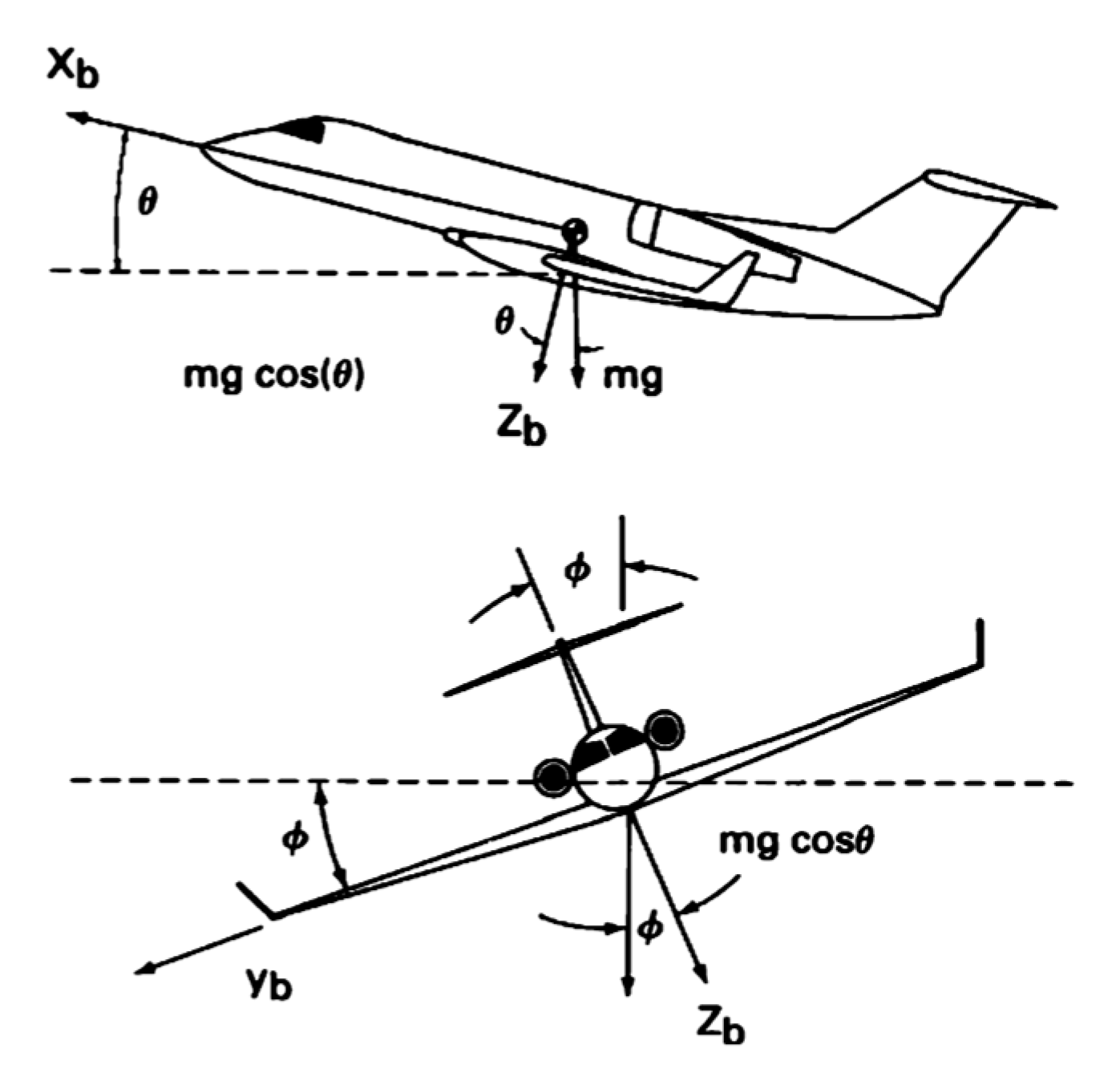
Figure A1. Components of gravitational force in body frame.
Fluids 08 00320 g0a1
Figure A2. Engines position on Boeing 747.
Fluids 08 00320 g0a2
Figure A3. Transformation cycle Between various axes.
Fluids 08 00320 g0a3
Figure A4. Interpreted MATLAB function block.
Fluids 08 00320 g0a4
Figure A5. Simulink canvas with turbulence and wind models embedded.
Fluids 08 00320 g0a5

Appendix B

BOEING 747-200 RESPONSE ANALYSIS UNDER CONTROLS INPUT AND ATMOSPHERIC CONDITIONS:
Aircraft Trim Conditions and Control Response at Sea-Level Flight Condition
(1)
Without Control Inputs.
Figure A6. Aircraft trim condition at sea level. The Simulink model was updated with sea level coefficients of the Boeing 747. The initial conditions provided correspond to longitudinal directions; therefore, the only variation in the longitudinal sets of state variables was observed. The aircraft entered phugoid-mode oscillation, which died out subsequently and the aircraft achieved its sea-level trim conditions. The trim longitudinal velocity achieved was approximately 225 m/s. The aircraft maintained 5–6° orientation with respect to the inertial frame under trim conditions.
Fluids 08 00320 g0a6
(2)
With Elevator Control Input.
Figure A7. Aircraft response to elevator control impulse input at sea level. An impulse elevator control input of 5° was provided to the aircraft to check the aircraft free-response behavior. The aircraft entered a long-period oscillation, which subsequently died out and the aircraft returned to its trimmed state. No variations in the lateral states were observed.
Fluids 08 00320 g0a7
Figure A8. Aircraft response to elevator control step inputs at sea level. The step input was initiated under the trim condition, and the flight state achieved new trim conditions through oscillations. To check the forced response, a 5° step elevator input was initiated, the aircraft entered oscillatory behavior that died out, subsequently achieving a new trim condition under the influence of constant elevator input. The response agreed with the theoretical knowledge regarding the variation trends in longitudinal sets of parameters.
Fluids 08 00320 g0a8
(3)
With Aileron/Rudder Control Inputs.
Figure A9. Aircraft response to aileron control impulse inputs. The effects of 5° aileron impulse control input on the state are shown. The longitudinal states remained unaffected, whereas lateral states were depicted as a short-period oscillation as a response to lateral control deflection, which died out, quickly regaining its original position. As yawing and rolling motions are coupled with each other, oscillations were recorded in both states. The bank angle ϕ recovered its original zero position; however, the yaw angle ψ reached a new position, as expected from theoretical knowledge. All states achieved trim state after oscillations, except for yaw angle, which reached a new trim condition.
Fluids 08 00320 g0a9
Figure A10. Aircraft response to rudder control impulse inputs at sea level. The effects of 5° rudder impulse control input on the state are shown. Similar behavior to that recorded for 5° aileron impulse input was observed. All the states achieved the initial trim state after oscillations, except for yaw angle, which reached a new trim condition.
Fluids 08 00320 g0a10
Figure A11. Aircraft response to aileron control step inputs at sea level. Under the step aileron input, the aircraft achieved new trim states through short-period oscillations. For the forced response, the aileron step input was generated and the aircraft exhibited short-period oscillation and reached a new trim state under the influence of a constant lateral input. The aircraft steady-state roll rate can be seen in Figure 10 for the 5° aileron step input.
Fluids 08 00320 g0a11
Aircraft Trim Conditions and Control Response Under Cruise Flight Conditions
Aircraft Response to Wind Turbulence and Wind Shear in Normal Flight
Figure A12. Aircraft trim condition at cruise altitude. The model was updated with the cruise parameters to capture aircraft behavior under cruise flight conditions. For the selected cruise conditions, the aircraft achieved trim flight conditions from the given initial conditions. The aircraft response behavior was similar to the sea-level conditions, except for the variation in oscillatory frequency. Moreover, the aircraft showed similar behavior to impulse and step control inputs for both longitudinal and lateral modes, as was demonstrated for sea-level conditions.
Fluids 08 00320 g0a12
Figure A13. Aircraft response to vertical gust of 20 ft/s for 50 s. The aircraft response for 50 s of vertical gust can be observed from vertical velocity ‘w’ and ‘Angle of Attack’ versus time curve. The aircraft flight states were disturbed from the trim setting, but regained it once the gust was removed after 50 s.
Fluids 08 00320 g0a13
Figure A14. Aircraft response to 3D gust of 10 ft/s for 10 s. The aircraft response to the 3D gust phenomenon can be observed in this figure. A constant velocity wind gust of 10 ft/s was generated under sea-level flight conditions for 10 s using Simulink wind shear and gust blocks. As expected, the aircraft linear and angular velocities, and Euler angles with respect to the inertial frame were disturbed for the period of wind gust. Once the gust was removed, the aircraft regained its trim conditions.
Fluids 08 00320 g0a14
Figure A15. Aircraft response to atmospheric turbulence at sea level. Simulations were conducted with the turbulence block ‘ON’. As wind turbulence is a three-dimensional phenomenon, all states were randomly vibrating about their trim positions. The random fluctuations were small in amplitude and unable to destabilize the system response, but continued fluctuating about their free-response behavior.
Fluids 08 00320 g0a15
Aircraft Response to Wind Turbulence and Wind Shear at Landing Phase
(1)
Landing Under Headwind and Tailwind Conditions.
(2)
Landing Under Crosswind Conditions.
(3)
Landing Under Vertical Wind Shear Conditions.
Aircraft Response to Microburst Under Landing Conditions.
Figure A16. Aircraft response to headwind and tailwind at landing. The aircraft, on a 3° glide slope, was subjected to 25 ft/s headwinds 7000 ft short of touchdown. The aircraft’s forward velocity ‘u’ is plotted against time ‘t’, whereas vertical displacement ‘Z’ is plotted against time ‘t’ and horizontal displacement ‘X’. The top set of figures represents ‘no wind conditions’, the middle set represents ‘headwind’, and the bottom set represents ‘tailwind’. The effective speed of the aircraft increased due to headwind, thus generating more lift. As a result, the aircraft gained height and was disturbed from its preset glide course. The aircraft experienced an overshoot of approximately 3000 ft from the touchdown point. Similarly, an undershoot of approximately 4000 ft was recorded for a case of a 25 ft/s tailwind condition due to the reduction in the effective forward speed. The undershoot and overshoot were increased to approximately 6000 ft once the wind velocity was increased to 30 ft/s.
Fluids 08 00320 g0a16
Figure A17. Aircraft response to crosswind conditions at landing. Aircraft side velocity ‘v’ is plotted against time ‘t’, whereas vertical displacement ‘Z’ and lateral displacement ‘Y’ are plotted against horizontal displacement ‘X’. The top set of figures represents ‘no wind conditions’, while the bottom set represents the ‘crosswind condition’. A case of a 25 ft/s 90° crosswind condition was also simulated and, as expected, the aircraft started drifting in the direction of crosswind. Under the simulated conditions, the aircraft became offset from its landing approach by approximately 450 ft. The glide slope and touchdown point were negligibly affected. Owing to inherent coupling, the roll and yaw rate along with variations in the roll and yaw angle were observed. Once the crosswind condition was reduced to 10 ft/s, the offset condition was also reduced to 180 ft from the initial course.
Fluids 08 00320 g0a17
Figure A18. Aircraft response to vertical wind shear conditions at landing. The aircraft’s forward velocity ‘u’ is plotted against time ‘t’, whereas vertical displacement ‘Z’ is plotted against time ‘t’ and horizontal displacement ‘X’. The top set of figures represents ‘no wind conditions’, the middle set represents ‘downwind gust’, and the bottom set represents ‘upwind gust’. Vertical wind shear simulations were set for a wind velocity of 25 ft/s. In the case of a downwind gust condition of 25 ft/s, the aircraft angle of attack was decreased, putting the aircraft into a steep glide slope of approximately 11–12° and undershooting the touchdown point by approximately 4000 ft. During an upwind gust condition, the effective angle of attack increased for the aircraft, thus increasing the overall lift of the aircraft. The aircraft momentarily gained height departing from its preset 3° glide slope before diving again at a higher glide slope of approximately 10° and overshooting touchdown point by a couple of hundred feet.
Fluids 08 00320 g0a18
Figure A19. Aircraft response to microburst at landing. The aircraft’s forward velocity ‘u’ and vertical velocity ‘w’ are plotted against time ‘t’, whereas vertical displacement ‘Z’ is plotted against horizontal displacement ‘X’. The top set of figures represents ‘no microburst conditions’, while the bottom set represents ‘microburst conditions’. A microburst with a maximum velocity of 25 ft/s was simulated. As the physical spread of the velocity profile was greater, the burst simulation was started at 32,000 ft short of the actual touchdown point. In the first phase, a headwind of 25 ft/s was built up and sustained for 10,000 ft and was transitioned into a sustained downwind of 25 ft/s for another 10,000 ft. In the last phase, the downwind was transitioned into a tailwind of 25 ft/s, which continued until touchdown. As expected, initially, the aircraft gained height in the headwind condition due to the increase in effective speed, departing from its 3° glide course, followed by a sharp dip under the influence of sustained downwind. The aircraft momentarily leveled off while transitioning from downwind to tailwind and then glided down at a sharp angle of ~14.5° under the influence of tailwind by effectively reducing the aircraft’s forward speed. Aircraft touchdown was ssapproximately 8000 ft short of the actual touchdown point. Moreover, the descent rate was also high on touchdown. It was the high glide slope angles and higher descent rate that led to aircraft crashes while encountering microbursts short of the runway.
Fluids 08 00320 g0a19

References

  1. Rizzi, A. Modeling and simulating aircraft stability and control—The SimSAC project. Prog. Aerosp. Sci. 2011, 47, 573–588. [Google Scholar] [CrossRef]
  2. Mehra, R.K.; Kessel, W.C.; Carroll, J.V. Global stability and control analysis of aircraft at high angles of attack. In Annual Technical Reports 1/2/3, ONR-CR215-(1/2/3), 1977/1978/1979; Scientific Systems Inc.: Woburn, MA, USA, 1977. [Google Scholar]
  3. Carroll, J.V.; Mehra, R.K. Bifurcation analysis of nonlinear aircraft dynamics. J. Guid. Control Dyn. 1982, 5, 529–536. [Google Scholar] [CrossRef]
  4. Winslow, J.; Otsuka, H.; Govindarajan, B.; Chopra, I. Basic understanding of airfoil characteristics at low Reynolds numbers (104–105). J. Aircr. 2018, 55, 1050–1061. [Google Scholar] [CrossRef]
  5. Goman, M.G.; Khramtsovsky, A.V. Computational framework for investigation of aircraft nonlinear dynamics. Adv. Eng. Softw. 2008, 39, 167–177. [Google Scholar] [CrossRef]
  6. Zagaynov, G.I.; Goman, M.G. Bifurcation analysis of critical aircraft flight regimes. In Proceedings of the 14th Congress of ICAS Paper, Toulouse, France, 9–14 September 1984; p. 84-4. [Google Scholar]
  7. Jahnke, C.C.; Culick, F.E.C. Application of bifurcation theory to the high-angle-of-attack dynamics of the F-14. J. Aircr. 1994, 31, 26–34. [Google Scholar] [CrossRef]
  8. Lowenberg, M.; Lowenberg, M. Bifurcation analysis as a tool for post-departure stability enhancement. In Proceedings of the 22nd Atmospheric Flight Mechanics Conference, New Orleans, LA, USA, 11–13 August 1997; p. 3716. [Google Scholar]
  9. Guicheteau, P. Bifurcation theory: A tool for nonlinear flight dynamics. Philos. Trans. R. Soc. Lond. Ser. A Math. Phys. Eng. Sci. 1998, 356, 2181–2201. [Google Scholar] [CrossRef]
  10. Planeaux, J. Bifurcation analysis of a model fighter aircraft with control augmentation. In Proceedings of the 17th Atmospheric Flight Mechanics Conference, Portland, OR, USA, 20–22 August 1990; p. 2836. [Google Scholar]
  11. Avanzini, G.; Matteis, G.D. Bifurcation analysis of a highly augmented aircraft model. J. Guid. Control Dyn. 1997, 20, 754–759. [Google Scholar] [CrossRef]
  12. Goman, M.; Khramtsovsky, A.; Goman, M.; Khramtsovsky, A. Global stability analysis of nonlinear aircraft dynamics. In Proceedings of the 22nd Atmospheric Flight Mechanics Conference, New Orleans, LA, USA, 11–13 August 1997; p. 3721. [Google Scholar]
  13. Littleboy, D.; Smith, P. Bifurcation analysis of a high incidence aircraft with nonlinear dynamic inversion control. In Proceedings of the 22nd Atmospheric Flight Mechanics Conference, New Orleans, LA, USA, 11–13 August 1997; p. 3717. [Google Scholar]
  14. Garrard, W.L. Suboptimal feedback control for nonlinear systems. Automatica 1972, 8, 219–221. [Google Scholar] [CrossRef]
  15. Sannomiya, N.; Itakura, H. A method for suboptimal design of nonlinear feedback systems. Automatica 1971, 7, 703–712. [Google Scholar]
  16. Bras, M.; Vale, J.; Lau, F.; Suleman, A. Flight dynamics and control of a vertical tailless aircraft. J. Aeronaut. Aerosp. Eng. 2013, 2, 1–10. [Google Scholar]
  17. Morris, C.; Allison, D.; Sultan, C.; Schetz, J.; Kapania, R. Towards flying qualities constraints in the multidisciplinary design optimization of a supersonic tailless aircraft. In Proceedings of the 12th AIAA Aviation Technology, Integration, and Operations (ATIO) Conference and 14th AIAA/ISSMO Multidisciplinary Analysis and Optimization Conference, Indianapolis, IN, USA, 17–19 September 2012; p. 5517. [Google Scholar]
  18. Finck, R.D. USAF Stability and Control DATCOM, AFWAL-TR-83-3048; McDonnel Douglas Corporation: Long Beach, CA, USA, 1978. [Google Scholar]
  19. Goetzendorf-Grabowski, T.; Antoniewski, T. Three surface aircraft (TSA) configuration–flying qualities evaluation. Aircr. Eng. Aerosp. Technol. Int. J. 2016, 88, 277–284. [Google Scholar] [CrossRef]
  20. Goetzendorf-Grabowski, T.; Figat, M. Aerodynamic and stability analysis of personal vehicle in tandem-wing configuration. Proc. Inst. Mech. Eng. Part G J. Aerosp. Eng. 2017, 231, 2146–2162. [Google Scholar] [CrossRef]
  21. Mader, C.A.; Martins, J.R. Stability-constrained aerodynamic shape optimization of flying wings. J. Aircr. 2013, 50, 1431–1449. [Google Scholar] [CrossRef]
  22. National Research Council. Low-Altitude Wind Shear and Its Hazard to Aviation; National Academies Press: Washington, DC, USA, 1983. [Google Scholar]
  23. Moser, W. Ted Fujita, Chicago’s Mr. Tornado, and The Super Outbreak of 1974. Online Chicago Magazine. Available online: https://www.chicagomag.com/city-life/april-2011/ted-fujita-chicagos-mr-tornado/ (accessed on 28 April 2011).
  24. Miele, A.; Wang, T.; Melvin, W.W. Guidance strategies for near-optimum take-off performance in a windshear. J. Optim. Theory Appl. 1986, 50, 1–47. [Google Scholar] [CrossRef]
  25. Bryson, A.E.; Zhao, Y. Feedback control for penetrating a downburst. In Proceedings of the Guidance, Navigation and Control Conference, Monterey, CA, USA, 17–19 August 1987; p. 2343. [Google Scholar]
  26. Leitmann, G.; Pandey, S. Aircraft control for flight in an uncertain environment: Takeoff in windshear. J. Optim. Theory Appl. 1991, 70, 25–55. [Google Scholar] [CrossRef]
  27. Seube, N.; Moitie, R.; Leitmann, G. Aircraft take-off in windshear: A viability approach. In Dynamical Systems and Control; CRC Press: Boca Raton, FL, USA, 2004; pp. 139–156. [Google Scholar]
  28. Chu, P.; Bryson, A., Jr. Control of aircraft landing approach in wind shear. In Proceedings of the 25th AIAA Aerospace Sciences Meeting, Reno, NV, USA, 24–26 March 1987; p. 632. [Google Scholar]
  29. Martynov, K.; Botkin, N.; Turova, V.; Diepolder, J. Real-time control of aircraft take-off in wind shear. Part I: Aircraft model and control schemes. In Proceedings of the IEEE 2017 25th Mediterranean Conference on Control and Automation (MED), Valletta, Malta, 3–6 July 2017; pp. 277–284. [Google Scholar]
  30. Avrenli, K.A.; Dempsey, B.J. A kinematic methodology to optimize the landing trajectory for the Boeing 737 jet undergoing total loss of thrust. J. Transp. Saf. Secur. 2017, 9, 82–104. [Google Scholar] [CrossRef]
  31. Nguyen, N.; Krishnakumar, K.; Kaneshige, J.; Nespeca, P. Flight dynamics and hybrid adaptive control of damaged aircraft. J. Guid. Control Dyn. 2008, 31, 751–764. [Google Scholar] [CrossRef]
  32. Dat, N.T.; Son, T.N.; Tra, D.A. Development of a flight dynamics model for fixed wing aircraft. In Proceedings of the 10th International Conference on Computer Modeling and Simulation, Sydney, Australia, 8–10 January 2018; pp. 202–205. [Google Scholar]
  33. Shah, G.; Hill, M. Flight dynamics modeling and simulation of a damaged transport aircraft. In Proceedings of the AIAA Modeling and Simulation Technologies Conference, Minneapolis, MN, USA, 13–16 August 2012; p. 4632. [Google Scholar]
  34. Sharma, U.; Nadda, S. Analysis and Control of Civilian Aircraft Model Using Simulink [PECS] 2020. In Modeling, Simulation and Optimization: Proceedings of CoMSO 2020; Springer: Singapore, 2021; pp. 613–622. [Google Scholar]
  35. Ahmad, M.; Hussain, Z.L.; Shah, S.I.A.; Shams, T.A. Estimation of stability parameters for wide body aircraft using computational techniques. Appl. Sci. 2021, 11, 2087. [Google Scholar] [CrossRef]
  36. Shams, T.A.; Shah, S.I.A.; Shahzad, A.; Javed, A.; Mehmood, K. Experimental investigation of propeller induced flow on flying wing micro aerial vehicle for improved 6DOF modeling. IEEE Access 2020, 8, 179626–179647. [Google Scholar] [CrossRef]
  37. Siddiqui, B.A.; Khushnood, A. Improving USAF DATCOM predictions of aircraft nonlinear aerodynamics. In Canadian Aeronautics and Space Institute AERO’09 Conference, Aerodynamics Symposium; Canadian Aeronautics and Space Institute: Kanata, ON, Canada, 2009; pp. 1–11. [Google Scholar]
  38. Shams, T.A.; Shah, S.I.A.; Ahmad, M.A. Study of Low Reynolds Number Aerodynamics for Low Aspect Ratio MAV Wing. In Proceedings of the 2018 IEEE 21st International Multi-Topic Conference (INMIC), Karachi, Pakistan, 1–2 November 2018; pp. 1–8. [Google Scholar]
  39. Tumse, S.; Tasci, M.O.; Karasu, I.; Sahin, B. Effect of ground on flow characteristics and aerodynamic performance of a non-slender delta wing. Aerosp. Sci. Technol. 2021, 110, 106475. [Google Scholar] [CrossRef]
  40. Zhang, X.; Zerihan, J. Off-surface aerodynamic measurements of a wing in ground effect. J. Aircr. 2003, 40, 716–725. [Google Scholar] [CrossRef]
  41. Tumse, S.; Karasu, I.; Sahin, B. Experimental investigation of ground effect on the vortical flow structure of a 40° swept delta wing. J. Aerosp. Eng. 2022, 35, 04022055. [Google Scholar] [CrossRef]
  42. Qu, Q.; Zuo, P.; Wang, W.; Liu, P.; Agarwal, R.K. Numerical investigation of the aerodynamics of an airfoil in mutational ground effect. AIAA J. 2015, 53, 3144–3154. [Google Scholar] [CrossRef]
  43. Tasci, M.O.; Pektas, M.C.; Tumse, S.; Karasu, I.; Sahin, B.; Akilli, H. The impact of the pitching motion on the structure of the vortical flow over a slender delta wing under sideslip angle. J. Vis. 2021, 24, 437–442. [Google Scholar] [CrossRef]
  44. Nuhait, A.O.; Zedan, M.F. Numerical simulation of unsteady flow induced by a flat plate moving near ground. J. Aircr. 1993, 30, 611–617. [Google Scholar] [CrossRef]
  45. Coesa, U.S. Standard Atmosphere, 1976; US Government Printing Office: Washington, DC, USA, 1976; Volume 40, p. 56. [Google Scholar]
  46. Mohamed, A.; Massey, K.; Watkins, S.; Clothier, R. The attitude control of fixed-wing MAVS in turbulent environments. Prog. Aerosp. Sci. 2014, 66, 37–48. [Google Scholar] [CrossRef]
  47. Jones, T. Statistical Data for the Boeing-747-400 Aircraft in Commercial Operations. Report No DOT/FAA/AR-04/44, Published by US Department of Transportation, Federal Aviation Administration, Office of Aviation Research. 2005. Available online: https://www.tc.faa.gov/its/worldpac/techrpt/ar04-44.pdf (accessed on 26 August 2020).
  48. Balatti, D.; Khodaparast, H.H.; Friswell, M.I.; Manolesos, M.; Castrichini, A. Aircraft turbulence and gust identification using simulated in-flight data. Aerosp. Sci. Technol. 2021, 115, 106805. [Google Scholar] [CrossRef]
  49. Wu, Z.; Cao, Y.; Ismail, M. Gust loads on aircraft. Aeronaut. J. 2019, 123, 1216–1274. [Google Scholar] [CrossRef]
  50. Liepmann, H.W. On the application of statistical concepts to the buffeting problem. J. Aeronaut. Sci. 1952, 19, 793–800. [Google Scholar] [CrossRef]
  51. De Karman, T.; Howarth, L. On the statistical theory of isotropic turbulence. Proc. R. Soc. Lond. Ser. A-Math. Phys. Sci. 1938, 164, 192–215. [Google Scholar] [CrossRef]
  52. Hakim, T.M.I.; Arifianto, O. Implementation of Dryden continuous turbulence model into simulink for LSA-02 flight test simulation. In Journal of Physics: Conference Series; IOP Publishing: Medan, Indonesia, 2018; Volume 1005, p. 012017. [Google Scholar]
  53. Dongli, M. An improvement of the digital simulation method for atmospheric turbulence. J. Beijing Univ. Aeronaut. Astronaut. 1990, 3, 57–63. [Google Scholar]
  54. Jing, P.; Chang, J.J. Research on the Numerical Simulation of Aircraft Carrier Air Wake. J. Beijing Univ. Aeronaut. Astronaut. 2000, 26, 340–343. [Google Scholar]
  55. Etkin, B. Turbulent wind and its effect on flight. J. Aircr. 1981, 18, 327–345. [Google Scholar] [CrossRef]
  56. Dryden, H.L. A review of the statistical theory of turbulence. Q. Appl. Math. 1943, 1, 7–42. [Google Scholar] [CrossRef]
  57. Xiao, Y. Digital generation of two-dimensional field of turbulence for flight simulation. Chin. J. Aeronaut. 1990, 3, 239–245. [Google Scholar]
  58. Beal, T.R. Digital simulation of atmospheric turbulence for Dryden and von Karman models. J. Guid. Control Dyn. 1993, 16, 132–138. [Google Scholar] [CrossRef]
  59. MIL-STD-1797A; Fling Qualities of Piloted Aircraft. Military Standard 1797A; Government Printing Office: Washington, DC, USA, 1990; p. 678.
  60. Nelson, R.C. Flight Stability and Automatic Control; WCB/McGraw Hill: New York, NY, USA, 1998; Volume 2. [Google Scholar]
  61. Roskam, J. Airplane Flight Dynamics and Automatic Flight Controls; DAR Corporation: Lawrence, KS, USA, 1998. [Google Scholar]
  62. Lambrechts, P.F.; Terlouw, J.C.; Doorn, J.T.M. Robust Flight Control Design Challenge Problem Formulation and Manual: The Research Civil Aircraft Model (RCAM). Garteur/TP-088-3. 1996. Available online: https://garteur.org/wp-content/reports/FM/FM_AG-08_TP-088-3.pdf (accessed on 26 August 2020).
  63. Irving, J.P. Robust Flight Control in a Computational Aircraft Control Engineering Environment. Garteur FM(AG08)/TP-088-2. 1995. Available online: https://garteur.org/wp-content/reports/FM/FM_AG-08_TP-088-2.pdf (accessed on 26 August 2020).
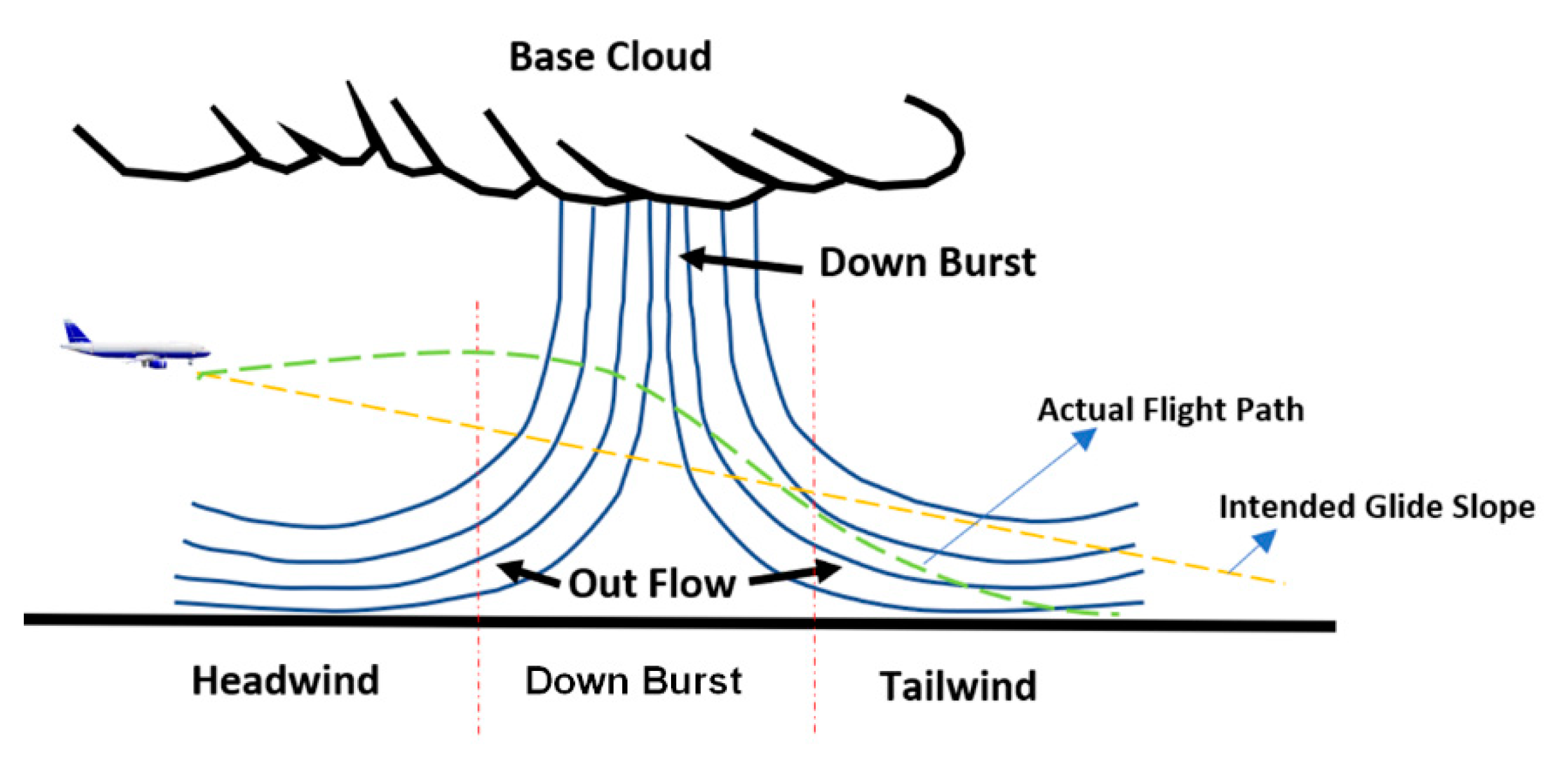
Figure 1. Microburst and its effect on relative wind and flight path.
Fluids 08 00320 g001
Figure 2. Aircraft axes systems and orientation of forces and moments on an aircraft.
Fluids 08 00320 g002
Figure 3. Proposed methodology for capturing non-linear flight dynamics with atmospheric conditions. The elements that are covered in the user-defined function (UDF) are highlighted with red borders.
Fluids 08 00320 g003
Figure 4. Proposed UDF flowchart and schematic with inputs and outputs.
Fluids 08 00320 g004
Figure 5. Non-linear aircraft model designed in Simulink canvas for detailed analysis.
Fluids 08 00320 g005
Figure 6. Aircraft trim condition at sea level under the influence of sea level coefficients. The initial conditions corresponded to the longitudinal directions; therefore, the only variation was observed in the longitudinal sets of state variables (i.e., u, w, q, and θ). The aircraft entered phugoid mode oscillation, which died out subsequently and the aircraft achieved sea level trim conditions. The trim longitudinal velocity achieved was approximately 225 m/s, with an orientation of 5–6° with respect to the inertial frame.
Fluids 08 00320 g006
Figure 7. Aircraft response to 5° elevator control step inputs at sea level. The step input was initiated at the trim condition; the aircraft entered oscillatory behavior, which died out, subsequently achieving a new trim condition under the influence of constant elevator input. The response agreed with the theoretical knowledge regarding the variation trends in the longitudinal set of parameters (i.e., u, w, q, and θ).
Fluids 08 00320 g007
Figure 8. Aircraft response to aileron control step inputs at sea level. Under the step aileron input, the aircraft achieved new trim states through short-period oscillations. Significant variations were observed in the lateral set of variables (i.e., v, p, r, ψ, and ϕ), whereas negligible variations were observed in the longitudinal set of variables. The aircraft achieved a steady-state roll rate under the influence of a 5° aileron step input.
Fluids 08 00320 g008
Figure 9. (a) Aircraft response to vertical gust of 20 ft/s for 50 s. The aircraft response can be observed from vertical velocity ‘w’ and ‘angle of attack’ versus time curve. The aircraft flight states were disturbed by the trim setting, but were regained once the gust was removed after 50 s. (b) Aircraft response to 3D gust of 10 ft/s in all directions for 10 s. As expected, the aircraft linear and angular velocities, and Euler angles with respect to inertial frame were disturbed for the period of wind gust. Once the gust was removed the aircraft regained its trim conditions.
Fluids 08 00320 g009
Figure 10. (a) Aircraft response to ‘no wind conditions’, (b) aircraft response to ‘headwind’, and (c) aircraft response to ‘tailwind’. The aircraft, on a 3° glide slope, was subjected to 25 ft/s headwinds 7000 ft short of touchdown. The effective speed of the aircraft increased due to headwind, thus generating more lift. As a result, the aircraft gained height and was disturbed from its preset glide course. The aircraft experienced an overshoot of approximately 3000 ft from the touchdown point. Similarly, an undershoot of approximately 4000 ft was recorded for a 25 ft/s tailwind condition due to the reduction in the effective forward speed. The undershoot and overshoot were increased to approximately 6000 ft once the wind velocity was increased to 30 ft/s.
Fluids 08 00320 g010
Figure 11. (a) Aircraft response to ‘no crosswind conditions’. (b) Aircraft response to ‘crosswind condition’. A case of a 25 ft/s 90° crosswind condition was also simulated and, as expected, the aircraft started drifting in the direction of the crosswind. Under the simulated conditions, the aircraft became offset from its landing approach by approximately 450 ft. Due to inherent coupling, the roll and yaw rates along with the variations in the roll and yaw angle were observed. Once the crosswind condition was reduced to 10 ft/s, an offset condition was also reduced to 180 ft from the initial course.
Fluids 08 00320 g011
Figure 12. (a) Aircraft response to ‘no wind shear’ and (b) aircraft response to vertical wind shear of 25 ft/s. In the case of a downwind gust (Dash Line), the aircraft’s angle of attack was decreased, putting the aircraft into a steep glide slope of approximately 11~12° and undershooting the touchdown point by approximately 4000 ft. During an upwind gust condition (solid line), the aircraft momentarily gained height, departing from its preset 3° glide slope before diving again at a higher glide slope of approximately 10° and overshooting the touchdown point by a couple of hundred feet.
Fluids 08 00320 g012
Figure 13. (a) Aircraft response to ‘no microburst conditions’ and (b) aircraft response to ‘microburst condition’. A microburst with a maximum velocity of 25 ft/s was simulated at 32,000 ft short of the actual touchdown point. In the first phase, a headwind of 25 ft/s was built up and sustained for 10,000 ft, followed by a sustained downwind of 25 ft/s for another 10,000 ft. In the last phase, a sustained tailwind of 25 ft/s continued until touchdown. As expected, initially, the aircraft gained height under the headwind condition due to the increase in effective speed, departing from its 3° glide course, followed by a sharp dip under the influence of sustained downwind. The aircraft momentarily leveled off while transitioning from downwind to tailwind and then glided down at a sharp angle of ~14.5° under the influence of tailwind by effectively reducing the aircraft’s forward speed. Aircraft touchdown was approximately 8000 ft short of the actual touchdown point. Moreover, the descent rate was also high on touchdown.
Fluids 08 00320 g013
Table 1. Summary of chosen input and output variables.
Input/OutputDefinitionRemarks
U(1)Aileron deflection for roll controlInput
U(2)Elevator deflection for pitch controlInput
U(3)Rudder deflection for yaw controlInput
U(4), U(5)Throttle controls for enginesInput
du/dt, dv/dt, dw/dtRate of change of linear velocitiesOutput
dϕ/dt, dθ/dt, dψ/dtRate of change of Euler velocitiesOutput
Table 2. Geometric aerodynamic coefficients selected from the literature.
ParameterApproachCruiseUnits
W564,000 (255,826)636,636 (288,773)Ib (kg)
S5500 (~510.9)5500 (~510.9)ft2 (m2)
c27.3 (8.3)27.3 (8.3)ft (m)
cg0.250.25
Ixx13,700,000 (18,574,705)18,200,000(24,675,886)Slug-ft2 (kg-m2)
Iyy30,500,000 (41,352,447)33,100,000 (44,877,574)Slug-ft2 (kg-m2)
Izz43,100,000 (58,435,753)49,700,000 (67,384,152)Slug-ft2 (kg-m2)
Ixz830,000 (1,125,328)970,000 (1,315,143)Slug-ft2 (kg-m2)
Longitudinal CoefficientsLateral Coefficients
CoeffApproachCruiseCoeffApproachCruise
CL11.760.52Clb−0.281−0.095
CD10.2630.045Clp−0.502−0.32
CM100Clr0.1950.2
CD00.07510.0305Cyb−1.08−0.9
Cdu00.22Cyp00
Cda1.130.5Cyr00
CL00.920.29Cnb0.1840.21
CLu−0.22−0.23Cnp−0.2220.02
CLa5.675.5Cnr−0.36−0.33
CLa.6.78Clda0.0530.014
CLq5.657.8Clδr00.005
Cmu0.071−0.09Cyδa00
Cma−1.45−1.6Cyδr0.1790.06
Cma.−3.3−9Cnδa0.0083−0.0028
Cmq−21.4−25.5Cnδr−0.113−0.095
CDδe00
CLδe0.360.3
Cmδe−1.4−1.2
Table 3. Summary of selected flight parameters.
ParameterUnitsApproachCruise
Hft (m)040,000 (12,192)
M-0.1980.9
TASft/s (m/s)221.0 (67.4)870.91 (265.24)
ρ ρSlug/ft3 (kg/m3)0.0023769 (4.6 × 10⁻⁶)0.0005873 (1.14 × 10⁻⁶)
QIb/ft2 (N/m-)58.0 (2777)222.72 (10,664)
αDeg8.52.4
Table 4. Validation of canvas results. The values presented are trim conditions for Boeing 747-200 at different altitudes (i.e., cruise and approach) taken from [61].
ParameterLiterature Value [61]Present WorkError
Approach Velocity221 ft/s225 ft/s1.8%
Cruise Velocity871 ft/s882 ft/s1.2%
Time Period (Phugoid)45.9 s43.5 s4.3%
Time Period (SP)9.13 s9.6 s5.1%
Disclaimer/Publisher’s Note: The statements, opinions and data contained in all publications are solely those of the individual author(s) and contributor(s) and not of MDPI and/or the editor(s). MDPI and/or the editor(s) disclaim responsibility for any injury to people or property resulting from any ideas, methods, instructions or products referred to in the content.