
Numerical Characterization of the Flow Dynamics and COP Estimation of a Binary Fluid Ejector Ground Source Heat Pump Cooling System


Mechanical Engineering Department, Prince Mohammad Bin Fahd University, Al Khobar 34218, Saudi Arabia
Fluids 2022, 7(7), 250; https://doi.org/10.3390/fluids7070250
Submission received: 25 May 2022
/
Revised: 4 July 2022
/
Accepted: 7 July 2022
/
Published: 20 July 2022
Abstract
:Ejector-based refrigeration systems can make direct use of many forms of thermal energy, such as solar thermal, waste heat, biogas, or natural gas. The present paper describes the estimation of the thermal coefficient of performance (COP) of a binary fluid ejector ground source heat pump (BFE GSHP) cooling system. A method for fluid selection was defined based on the favorable thermo-physical properties of the working fluids. A short list of fluid pairs were selected based on their favorable properties for the BFE GSHP cooling system. Computational Fluid Dynamics (CFD) investigation was conducted for the selected fluid pairs and a suitable ejector geometry is proposed for the high compression ratios encountered in the GSHP applications. The mixing between primary and secondary fluids was investigated using physical analysis of the CFD results. The effect of the fluids’ thermo-physical properties on the system performance was also discussed.
1. Introduction
The ground source heat pump (GSHP), often referred to as a “geothermal heat pump”, is one of the most energy-efficient technologies for space air conditioning and/or water heating. These systems offer substantial benefits to consumers and utilities in terms of both energy (kWh) and demand (kW) savings. The savings attributable to the use of GSHP systems in residential and commercial buildings are dependent on a large number of factors that can affect the system’s performance, such as the local climate, GSHP system type, equipment efficiency, soil conditions, sizing, etc. In the present study, a binary fluid ejector (BFE) GSHP cooling system was considered and analyzed under realistic operating conditions.
The basic BFE GSHP system includes a compression device, an expansion device, a boiler, an evaporator, a condenser, and a water ground loop. The difference from a conventional mechanical GSHP is that the mechanical compression device is replaced by an ejector to compress the refrigerant vapor to the condenser saturation pressure. The ejector is driven by a high-pressure motive vapor supplied by the boiler. This is of particular advantage in using a low-grade thermal resource such as solar thermal or waste heat from industrial processes or residential fuel cells. A high-efficiency ejector-based GSHP can present significant primary energy saving as compared with an electrical or mechanical GSHP. Such advantage warrants a serious re-visit to the technology, especially to re-evaluate the potential and feasibility of developing an ejector-based ground source heat pump systems.
The entrainment ratio (ratio between the mass flow rate of the secondary fluid and that of the primary fluid) is one of the most important parameters that influences the COP of ejector refrigeration systems [1,2,3,4]. Many researchers have shown the need to improve the ejector performance in order to make ejector-based systems economically more attractive. It was also shown that the choice of the operating fluid has a significant influence on the ejector performance [5,6,7]. Several studies showed that the ejector configuration strongly affects the performance of an ejector refrigeration system [3,8,9,10,11,12]. It was also found that when two chemically distinct fluids are used in the forward and reverse Rankine cycles of an ejector refrigeration system, the system COP can be enhanced [4,13]. It is important to note that the enhancement of the ejector performance also depends on the proper selection of the binary fluids with an optimal set of thermo-physical properties for each application.
El Hassan et al. [12] studied the influence of the thermo-physical properties of the primary and secondary fluids on the ejector performance for distillation application. The authors found that the entrainment ratio is mostly a function of fluids properties, the ejector geometry, and the operating conditions. It was shown that the entrainment ratio decreased with increasing the molecular mass of the primary fluid. However, the entrainment ratio increased with the molecular mass of secondary fluid.
Recently, Xiao et al. [14] studied the flow separation inside a supersonic ejector using CFD methods. These authors found that the realizable k-ε model with the two wall treatments and the SST k-w model were the most accurate in predicting the flow dynamics inside the ejector. They also evidenced that the location of the secondary shock process varies with the back pressure (ejector exit pressure). The shock will move upstream into the ejector throat as the back pressure increases, but the mixing process is not disturbed, and the secondary flow remains choked [14].
Han et al. [15] studied the effect of the back pressure and the ejector throat diameter on the boundary layer separation from the ejector wall. They found that the ejector works in back-flow mode (increased boundary layer separation) when the back pressure exceeds the critical value. It was also shown that for a too-small throat, the separation of the boundary layer is caused by the increase of adverse pressure gradient and a decrease of the effective area of the secondary fluid. For a too-large ejector throat diameter, the back pressure propagates upstream due to the absence of shock waves and thus the boundary layer separates.
Buyadgie et al. [16] studies the performance of a binary fluid ejector refrigeration system (BFE-RS) using zeotropic fluid pairs. They found that for a high performance of the BFE-RS, the primary fluid (boiler side) should exhibit high molecular weight, low latent heat of evaporation, high normal boiling temperature, and high compressibility factor. On the other side, a refrigerant fluid (evaporator side) should have a low molecular weight, high latent heat of evaporation, low boiling point, and low compressibility factor.
Buyadgie et al. [17] used a BFE refrigeration to achieve congelation that is used with distillation in a solar-driven desalination process. It was found that the BFE-RS has 1.5-times higher efficiency than a single-fluid ejector RS. In addition, the combined system has the lowest price and the highest durability.
The main challenge facing the single-fluid ejector-based refrigeration systems is their low thermal efficiency as compared with existing technologies. Therefore, a highly efficient ejector would play a critical role in unlocking the wide spread use of renewable energy such as waste heat, solar thermal, and geothermal. In addition to proper fluid selection, the entrainment ratio is one of the most critical parameters that affect the system COP. This quantity is dependent on the mixing between the primary and the secondary fluids inside the ejector. Therefore, a good understanding of the mixing mechanism, and thus the entrainment, is of high interest for the proper choice of ejector geometry according to the fluids properties and the system operating conditions. Computational Fluid Dynamics (CFD) modeling was conducted, using many fluid pairs selected for the BFE GSHP cooling application, in order to understand the entrainment mechanism inside the ejector. The detailed description of the flow dynamics, for different fluid combinations and various operating conditions, can result in a proper choice of both the motive saturation temperature (in the boiler) and the ejector geometry for a better system performance. In the present paper, preliminary single-fluid CFD modeling for different compression ratios was considered to allow an appropriate choice of the ejector geometry. The binary fluid CFD results (for the selected fluid pair candidates), and the influence of both the compression ratio (CR) and the condenser temperature on the entrainment ratio were discussed.
The main objective of the present study was to estimate the COP of an ejector GSHP cooling system using CFD modeling for the entrainment ratio estimation. The operating temperatures of the studied system were selected according to real GSHP cooling systems used in the United States and Canada [18]. Fluids’ selection and ranking method was defined and used for finding fluid candidates based on their favorable thermo-physical properties for the BFE GSHP cooling application. An algorithm that can interrogate thousands of potential working fluids in multiple databases was developed in order to facilitate the binary fluid selection process. In this way, a short list of binary fluids candidates, based on their thermo-physical properties as high-performing candidates for GSHP cooling application, were selected and used for the CFD modelling.
Most previous investigations on ejector-based refrigeration systems considered well-known refrigerants as the working fluid. In the present work, however, the choice of the fluids was performed from databases with more than 30,000 fluids based on their thermo-physical properties that result in enhanced system performance. Such a new approach provides a greater choice of fluids and can be adopted when a new technology needs to be compared to existing ones.
2. Refrigeration COP Calculation
There are numerous parameters affecting the COP of a BFE GSHP cooling system. A Block diagram of such a cycle is shown in Figure 1. The temperature operating conditions are: boiler temperature TBoil = 200 °C; evaporator temperature TEvap = 19 °C, and condenser temperature TCond = 30 °C. The system was considered adiabatic and any pressure losses were neglected, and so saturated vapor pressures corresponding to the operating temperatures were used.
The COP is expressed as follows:
COP of a second law ideal BFE-RS can be estimated by replacing the heat flux ratios in Equation (1) with the ratio of temperatures (linear temperature scale defined on the basis of the Carnot cycle).
Equation (2) shows that the smaller the difference between the evaporator and condenser temperatures, the higher the Carnot cycle efficiency. Increasing the temperature of the boiler also increases the COP; however, one must also consider the influence of such an increase on the specific heat of the primary fluid. Indeed, the specific heat of the primary fluid increases with the boiler temperature and this is not favorable for the COP (See Equation (3). For an actual BFE-RS, considering that the enthalpy change occurring between the inlets and exits of the evaporator, boiler, and condenser is approximated by the enthalpies of vaporization, Equation (2) can be rearranged as follows:
where and are the enthalpy of vaporization at the evaporator (secondary fluid) and the boiler (primary fluid) temperature, respectively; and are the average specific heat capacity of the primary fluid (between the boiler and condenser) and the secondary fluid (between the evaporator and condenser); and is the mass entrainment ratio. The parameter is introduced to represent the term:
The binary fluid candidates that were selected for CFD modeling are presented in Table 1.
3. Ejector Geometry and CFD Simulations
The most common geometry of a supersonic refrigerant ejector consists of a mixing chamber, a throat, and a diffuser. The high-speed primary flow, emanating from the supersonic nozzle, entrains and mixes with the secondary flow. In the diffuser, the static pressure increases to equal that downstream of the ejector. The dimensions of major ejector parts are given in Figure 2. This ejector geometry is based on that of Eams et al.’s study [9]. However, some differences exist between the geometries of that and the present study [19].
Different turbulence models have been evaluated in previous studies for the flow prediction inside supersonic ejectors. In this study, the SST k–omega () model was used. Bartosiewicz et al. [20] compared the predicted pressure distribution on the ejector centerline and concluded that the prediction by the SST model provided the best agreement with the experimental results.
The equations of the turbulence model used in this study are as follows:
Equation for the turbulence kinetic energy:
Equation for the specific dissipation rate:
where ; ; .
The optimum number of cells was determined using a grid independence study. For a better flow prediction, the computational domain was divided into sub-domains and only quadrilateral cells were used. A grid refinement was performed in the boundary layers, shear flows, and in the region where shock waves develop (Figure 3). The optimum number of grids was found as between 260,000 and 340,000 for the different CFD cases (Figure 4). The compressible steady state form of the flow field was solved in a two-dimensional axisymmetric plane of the ejector. The time averaged Navier–Stokes equations for variable density flows were used and the energy equation was solved. The commercial CFD package ANSYS FLUENT 16 was used to implicitly solve the governing equations. A second-order upwind scheme was chosen for the spatial discretization of the convective terms and the QUICK method was selected for the discretization of the turbulent equations. Pressure inlet boundary conditions were set for the primary and the secondary fluids and the pressure outlet was set at the exit of the ejector (Figure 5).
The convergence of the CFD simulations occurred when the residual for each governing equation reduced to a value less than 10−6. The same 2D-axisymmetric CFD model of the present investigation was used in our previous studies [2,15]. A good agreement was shown between the CFD and the experimental measurements. The uncertainty of the numerical model for predicting the entrainment ratio was less than 1% [15]. It was also shown that the difference between the experimental measurements and the numerical prediction of the exit temperature was 2.6% [15].
4. Results and Discussion
4.1. Binary Fluid Pair Assay and Ranking
In order to improve the performance of BFE GSHP systems, a proper method had to be defined for the selection of the fluid pair. The primary objective in the fluid selection process is to select fluids that result in a higher ejector performance and thus increase the system efficiency. Since the compression ratio is of high importance for the ejector operation, the main criterion in the defined fluid selection algorithm was a low compression ratio. In addition, the favorable combination of fluid properties was another important criterion. An iterative search of binary fluids was performed using two databases (NIST and YAWS handbook), containing a total number of fluids higher than 30,000.
It is known that the compression ratio is strongly dependent on the equilibrium saturation pressure of the fluids mixture (back pressure) in the condenser. In the present work, this saturation pressure was assumed as the sum of the saturation pressure of the two fluids in their pure states (at the condenser temperature). Such an assumption is conservative as it is unfavorable for the COP estimation because it results in the highest compression ratio, which in reality can only occur for a heteroazeotropic fluids mixture.
For the present application, the number of available refrigerant candidates with low molecular mass was limited to a few compounds in the NIST database. Of these candidates, only methanol had a molecular mass smaller than 40 g/mol. As fh is proportional to the molecular mass ratio M1/M2, and a lower molecular mass of the primary fluid results in a higher momentum in the jet core, one should consider refrigerant candidates with a low molecular mass. Further, the candidates also require favorable thermo-physical properties for the studied application. Therefore, in order to broaden the number of potential refrigerants, the YAWS handbook database was consulted for the selection process of the secondary fluid. It should be noted that the primary fluids were always taken from the NIST database, whereas the blue symbols in Figure 6 use secondary fluids from the YAWS handbook database. It can be seen that three refrigerant candidates, with molecular mass less than 31 g/mol (Figure 6c, three vertical blue columns of round markers at the left), resulted in compression ratios generally lower than 2 and importantly a binary fluid compression ratio around 1.6 (Figure 6d). Such fluid pairs would be favorable for high entrainment ratios and high system COP. It was also shown (Figure 6b) that the primary pressure range was similar to that obtained with only the NIST database. Moreover, few additional secondary fluids with molecular mass smaller than 50 g/mol were extracted from the YAWS handbook database (Figure 6c). Those refrigerants could be considered in future investigations but first their environmental/safety criteria need to be characterized.
4.2. Entrainement Ratio Using Single Fluid Ejector
In order to properly choose the ejector geometry, preliminary single fluid CFD simulations were conducted using water vapor as the working fluid. It should be noted that the saturation pressures differed from their actual value at the studied working temperatures (TEvap = 19 °C and TCond = 30 °C). The main objective of these CFD simulations was to define the range of primary saturation pressure for different compression ratios for two different saturation pressures in the evaporator (7.33 and 12.26 KPa). The results are presented in Figure 7, and were compared to the theoretical model proposed by ref. [9] for a similar ejector geometry. It is interesting to note that the ejector can operate at a compression ratio as high as 3.4.
It can be seen in Figure 7 that for a compression ratio of 1.68, the highest entrainment ratio was achieved for P1 = 0.4 MPa when P2 = 7.33 KPa, whereas almost the same entrainment ratio was obtained for P1 = 0.7 MPa when P2 = 12.26KPa (green symbol in Figure 7). This result is not surprising, but is of interest and should be taken into account during the fluids selection process. A lower saturation pressure in the evaporator will be associated with a lower heat load for the boiler, thus reducing the energy loss and increasing the efficiency of the overall system.
One should also note that a lower primary saturation pressure can achieve a higher entrainment ratio when the compression ratio decreases. This is shown when comparing the compression ratio of 1.68 and 2.13 for the evaporator saturation pressure of 12.26 KPa (Figure 7). This information is helpful for investigating real-time boiler load, where the BFE GSHP is operating with a variable condenser temperature, resulting in different compression ratios across the ejector.
Han et al. [15] found that the supersonic ejector no longer has the ability to pump any fluid (ER is nearly zero) when the back pressure is higher than 6.15 kPa. Since the compression ratio of their study did not exceed 2.0, it can be suggested that the ejector geometry was not optimal for the higher compression ratios. This could justify the dramatic flow separation from the ejector walls and the resulting back-flow regime.
4.3. CFD Simulations for Selected Binary Fluid Candidates
The COP calculation of the BFE GSHP system requires a proper selection of the primary–secondary fluid pairs, and the estimation of the entrainment ratio inside the ejector. The primary and secondary saturation pressures are taken from the NIST and YAWS databases (Section 4.1). The boiler saturation pressures were chosen based on the preliminary single fluid CFD modeling (Section 4.2) in order to provide the required flow momentum required to entrain the secondary fluid and to minimize the pressure and friction losses inside the ejector. It is shown that such a choice should consider the influence of the binary fluid properties (e.g., their molecular masses) on the flow dynamics. As stated above, the equilibrium saturation pressure of the mixture in the condenser is considered as the sum of the saturation pressures of the primary and the secondary fluids at the condenser temperature. The main objective of the present Section is to study the influence of the molecular masses of the fluids, and that of the molecular mass ratio (M1/M2), on the entrainment mechanism and the system COP. As the number of refrigerants with low molecular mass is limited in the NIST database, this study only considered two secondary fluids: methanol and acetonitrile. The primary fluids were chosen to cover wide ranges of primary molecular mass (80.17 to 304 g/mol) and fh (1.97 to 7.68).
Table 2 presents the thermal COP based on the ER obtained from the CFD results for different compression ratios (CR) and molecular mass ratios (M1/M2). It was shown that the entrainment ratio (ER) was highly dependent on the molecular mass ratio and that in general the ER decreased when the molecular mass ratio increased. The highest ER was observed for a M1/M2 around 3 while the COP reaches its highest value for M1/M2 = 6.19; the corresponding primary molecular mass in this case was M1 = 198 g/mol. It should be noted that the difference between the compression ratios of different cases is not significant. However, future work which includes experimental measurement of the equilibrium saturation pressure of the fluid mixture could indicate very different compression ratios than those assumed in this study. This would in turn result in higher COP values. Since the choice of the primary pressure is strongly dependent on the ejector geometry, which in turn requires optimization for the chosen binary fluids, the final choice of the binary fluids for the real world application should be defined once the fluid interactions for different fluid candidates has been empirically tested.
Table 2 also shows that the entrainment ratio depends on the secondary molecular mass (M2). For example, the entrainment ratio was slightly lower for M1/M2 = 4.3 than for M1/M2 = 6.19. This could be related to the higher molecular mass of the acetonitrile as compared with the methanol. Indeed, the higher molecular mass can lead to a lower momentum of the secondary flow and higher velocity gradients in the mixing layer. Therefore, the shear forces become stronger and the entrainment ratio decreases.
The preliminary binary fluid CFD results showed that the first three fluids of Table 2 produced the highest COP. Therefore, these fluid pair candidates were further investigated using additional CFD modeling.
The mixing between the primary and the secondary fluids is mainly affected by both the development of the instabilities and the vortical structures that are generated near the jet exit and the resulting shear forces in the mixing layer. In addition, the entrainment ratio is highly affected by the presence of flow separation on the mixing chamber wall. Therefore, the flow dynamics were analyzed from the jet exit to the middle of the ejector throat in order to investigate the most crucial flow physics that influence the entrainment mechanism.
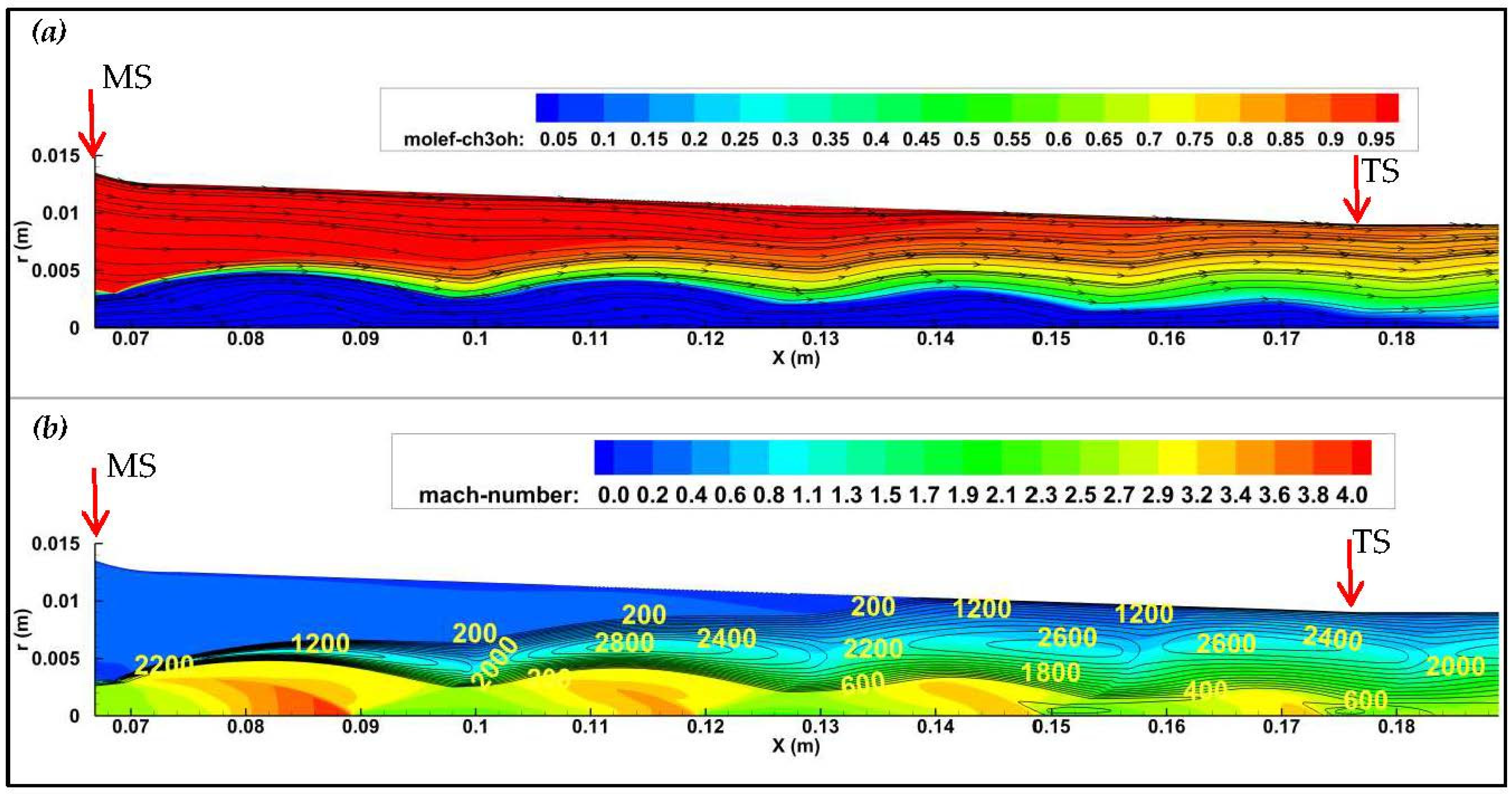
The CFD results were analyzed from investigating the distributions of both the Mach number and the turbulent kinetic energy (TKE) in the mixing chamber and the ejector throat (Figure 8b, Figure 9b, Figure 10b). Iso-values of the Mach number aim to illustrate the supersonic core and its expansion inside the ejector. The streamlines are shown to describe the flow trajectory and to identify possible flow recirculation regions inside the mixing chamber (Figure 8a, Figure 9a, Figure 10a). The molar fraction of methanol is also shown in these Figures. It should be noted that in all Figures, MS denotes the location where the fifth order polynomial ends inside the Mixing Section (MS), TS denotes the beginning of the ejector Throat Section (TS), and DS denotes the beginning of the ejector Diffuser Section (DS).
For the difluorodiiodomethane–methanol fluid pair (case 1), the streamlines showed a small localized recirculation region upstream of the ejector throat (0.13 m < X < 0.14 m; Figure 8a). The effect of such a small flow separation on the entrainment ratio can be expected to be minor. Figure 6b shows that the flow expanded when traveling from the jet exit towards the ejector throat and led to a shear layer/ boundary layer interaction which energized the boundary layer and reduced the size of the recirculation region. Moreover, the Mach number distribution (Figure 8b) showed a choked flow inside the ejector throat which resulted in a constant mass flow rate. Due to the high adverse pressure gradient (resulting from the high compression ratio CR = 2.36), the choked flow is helpful in minimizing the recirculation region.
For the bromofluoroiodomethane–methanol fluid pair (case 2), a slight improvement in the mixing between the primary and the secondary fluids was achieved compared with case 1. Furthermore, this fluid pair resulted in a smaller recirculation region on the ejector wall (Figure 9a). The higher turbulent kinetic energy values (Figure 9b) could be related to the presence of more developed azimuthal vortical structures in the jet shear layer. Therefore, the generation of streamwise vortices, favorable for mixing and a higher entrainment ratio, would be more pronounced [21].
The lower primary pressure for the bromotrichloromethane–methanol fluid pair (case 3) as compared with the previous two cases (cases 1 and 2) is responsible for a less expanded supersonic core and weaker shock waves inside the ejector (Figure 10b). The turbulent instabilities were thus more developed and the resulting turbulent kinetic energy values were higher near the jet exit and along the mixing chamber. This led to better mixing as can be seen from the molar fraction distribution at the ejector throat inlet in case 3 (Figure 10a) when compared with cases 1 and 2 (Figure 8a and Figure 9a). Such a behavior and the absence of flow separation on the ejector wall resulted in a higher entrainment ratio for case 3.
5. Conclusions
In the present paper, the COP of a BFE GSHP system providing space cooling duty was estimated for a short list of the binary fluid candidates, and a set of operating conditions. The entrainment mechanism inside the supersonic ejector was investigated using flow analysis based on CFD results.
It was found that the lowest COP of 1.55 corresponded to the highest compression ratio 2.36, while the highest reported COP 3.06 was found for the lowest compression ratio 1.55. It should be noted that the COP of 3.06 is based on a compression ratio estimate representing the summation of partial pressures of the binary fluid components, which means a conservative approach was used. Future work, including optimization of the ejector geometry based on the binary fluids selected, also has the potential to increase refrigeration and system COP.
The CFD simulations showed that the proper choice of the ejector geometry led to its operation at compression ratios as high as 3.4. In addition, the saturation pressure of the primary fluid strongly affected the momentum of the supersonic jet, the expansion of the jet, and the strength of the shock waves inside the ejector. Therefore, this parameter needs to be properly chosen for a given compression ratio and fluid pair candidates to ensure better entrainment of the secondary fluid and thus an optimal system performance.
It was also found that for most cases the entrainment ratio decreased when the molecular mass ratio increased. The highest ER was observed for a M1/M2 around 3. However, the COP reached its peak value for M1/M2 = 6.19 (for M1 = 198 g/mol). The flow analysis also suggested that the higher molecular mass of the secondary fluid can lead to a lower momentum and higher velocity gradients in the mixing layer. Therefore, the shear forces become stronger and the entrainment ratio decreases.
A wide range of primary molecular masses (M1) were considered in the CFD modeling. It was found that M1 affected the flow momentum of the primary jet and thus the entrainment ratio. On the other hand, the shear forces became stronger when the secondary molecular mass increased, leading to a decrease in the entrainment ratio. With methanol as the secondary fluid, the mass entrainment ratio presented a peak for M1/M2 ≃ 3.
Therefore, the optimal choice of the binary fluid candidates should account for both their thermo-physical properties, but also their mixing under specific set of operating conditions.
This present study of the BFE GSHP cooling application represents an important first step in realizing such a concept. The presented insights regarding the flow dynamics inside the ejector for different fluid combinations and operating conditions is of high interest to reach this goal. Further empirical investigations should be conducted for final choice of the working fluids and the optimization of the ejector geometry. Other working fluid properties, such as their toxicity, flammability, and environmental impact should be considered when considering a potential commercialization of the BFE GSHP systems.
Funding
This research was carried out with the financial support of May Ruben Technologies.
Acknowledgments
The author would like to thank both Canadian companies “May Ruben Technologies” and “Thermo-Fluids Solutions” for their financial and technical support of the present research work.
Conflicts of Interest
The authors declare no conflict of interest.
Nomenclature
| Acronyms | |
| BFE GSHP | Binary Fluid Ejector Ground Source Heat Pump |
| COP | Coefficient of Performance |
| CFD | Computational Fluid Dynamics |
| CR | Compression Ratio |
| TKE | Turbulent Kinetic Energy |
| MS | Mixing section |
| TS | Throat section |
| DS | Diffuser section |
| M1 | Molecular mass of the primary fluid |
| M2 | Molecular mass of the secondary fluid |
| Symbols | |
| TBoil | Boiler Saturation Temperature |
| TEvap | Evaporator Saturation Temperature |
| TCond | Condenser Saturation Temperature |
| QS,Evap | Refrigeration capacity |
| QP,Boil | Heat load for Boiler |
| QP,Cond | Heat rejection from Condenser |
| Enthalpy of vaporization in the Evaporator (secondary fluid) | |
| Enthalpy of vaporization in the Boiler (primary fluid) | |
| Average specific heat capacity of primary fluid | |
| Average specific heat capacity of secondary fluid | |
| Mass entrainment ratio |
References
- El Hassan, M.; Gubanov, A.; May, W.; Martinuzzi, R. Numerical investigation of the flow dynamics of a supersonic fluid ejector. In Proceedings of the International Conference on Heat Transfer and Fluid Flow, Prague, Czech Republic, 11–12 August 2014. [Google Scholar]
- El Hassan, M.; Bukharin, N. Numerical investigation of the flow dynamics inside single fluid and binary fluid ejectors. J. Phys. Conf. Ser. 2019, 1276, 012012. [Google Scholar] [CrossRef]
- Chunnanond, K.; Aphornratana, S. An Experimental investigation of a steam ejector refrigerator: The analysis of the pressure profile along the ejector. Appl. Therm. Eng. 2004, 27, 311–322. [Google Scholar] [CrossRef]
- Buyadgie, D.I.; Nichenko, S.V.; Buyadgie, O.D. Novel ejector cooling technologies using binary fluids. In Proceedings of the 9th International Conference on Sustainable Energy Technologies, Shanghai, China, 24–27 August 2010. [Google Scholar]
- Eames, I.W.; Ablwaifa, A.E.; Petrenko, V. Results of an experimental study of an advanced jet-pump refrigerator operating with R245fa. Appl. Therm. Eng. 2007, 27, 2833–2840. [Google Scholar] [CrossRef]
- Sankarlal, T.; Mani, A. Experimental investigations on ejector refrigeration system with ammonia. Renew. Energy 2007, 32, 1403–1413. [Google Scholar] [CrossRef]
- Varga, S.; Lebre, P.S.; Oliveira, A.C. Readdressing working fluid selection with a view to designing a variable geometry ejector. Int. J. Low-Carbon Technol. 2015, 10, 205–215. [Google Scholar] [CrossRef] [Green Version]
- El Zohbi, B.; Bukharin, N.; Assoum, H.H.; Abed-Meraim, K.; Sakout, A.; El Hassan, M. Investigation of the effects of the jet nozzle geometry and location on the performance of supersonic fluid ejectors. Energy Rep. 2022, 8, 228–233. [Google Scholar] [CrossRef]
- Eames, I.W.; Aphornratana, S.; Haider, H. A theoretical and experimental study of a small-scale steam jet refrigerator. Int. J. Regrigeration 1995, 18, 378–386. [Google Scholar] [CrossRef]
- Eames, I.W. A new prescription for the design of supersonic jet pumps: The constant rate of momentum change method. Appl. Therm. Eng. 2002, 22, 121–131. [Google Scholar] [CrossRef]
- Chunnanond, K.; Aphornratana, S. Ejectors: Applications in refrigeration technology. Renew. Sustain. Energy Rev. 2004, 8, 129–155. [Google Scholar] [CrossRef]
- Chang, Y.J.; Chen, Y.M. Enhancement of a steam-jet refrigerator using a novel application of the petal nozzle. Exp. Therm. Fluid Sci. 2000, 22, 203–211. [Google Scholar] [CrossRef]
- El Hassan, M.; Assoum, H.H.; Bukharin, N.; Abed-Meraim, K.; Sakout, A. Investigation of thermo-physical fluid properties effect on binary fluid ejector performance. Energy Rep. 2020, 6, 287–292. [Google Scholar] [CrossRef]
- Xiao, J.; Wu, Q.; Chen, L.; Ke, W.; Wu, C.; Yang, X.; Yu, L.; Jiang, H. Assessment of Different CFD Modeling and Solving Approaches for a Supersonic Steam Ejector Simulation. Atmosphere 2022, 13, 144. [Google Scholar] [CrossRef]
- Han, Y.; Wang, X.; Sun, H.; Zhang, G.; Guo, L.; Tu, J. CFD simulation on the boundary layer separation in the steam ejector and its influence on the pumping performance. Energy 2019, 167, 469–483. [Google Scholar] [CrossRef]
- Buyadgie, D.; Buyadgie, O.; Artemenko, S.V.; Chamchine, A.; Drakhnia, O. Conceptual design of binary/multicomponent fluid ejector refrigeration systems. Int. J. Low-Carbon Technol. 2012, 7, 120–127. [Google Scholar] [CrossRef] [Green Version]
- Buyadgie, O.; Drakhnia, O.; Miyazaki, T. The analysis of binary fluid ejector assisted solar desalination system. In Proceedings of the 17th International Refrigeration and Air Conditioning Conference. Purdue University, West Lafayette, IN, USA, 9–12 July 2018. [Google Scholar]
- Liu, X.; Munk, J. Field Test and Evaluation of Residential Ground Source Heat Pump Systems Using Emerging Ground Coupling Technologies. In Proceedings of the 11th International Energy Agency Heat Pump Conference, Montréal, QC, Canada, 11–12 May 2014. [Google Scholar]
- El Hassan, M. Numerical Investigation of the Flow Dynamics Inside Supersonic Fluid Ejector. Arab. J. Sci. Eng. 2019, 45, 909–919. [Google Scholar] [CrossRef]
- Bartosiewicz, Y.; Aidoun, Z.; Desevaux, P.; Mercadier, Y. Numerical and experimental investigations on supersonic ejectors. Int. J. Heat Fluid Flow 2005, 26, 56–70. [Google Scholar] [CrossRef]
- El Hassan, M.; Meslem, A. Time-resolved stereoscopic particle image velocimetry investigation of the entrainment in the near field of circular and daisy-shaped orifice jets. Phys. Fluids 2010, 22, 035107. [Google Scholar] [CrossRef]
Figure 1.
Block diagram of the BFE GSHP cooling system.

Figure 2.
Schematic view and dimensions of the supersonic binary fluid ejector.
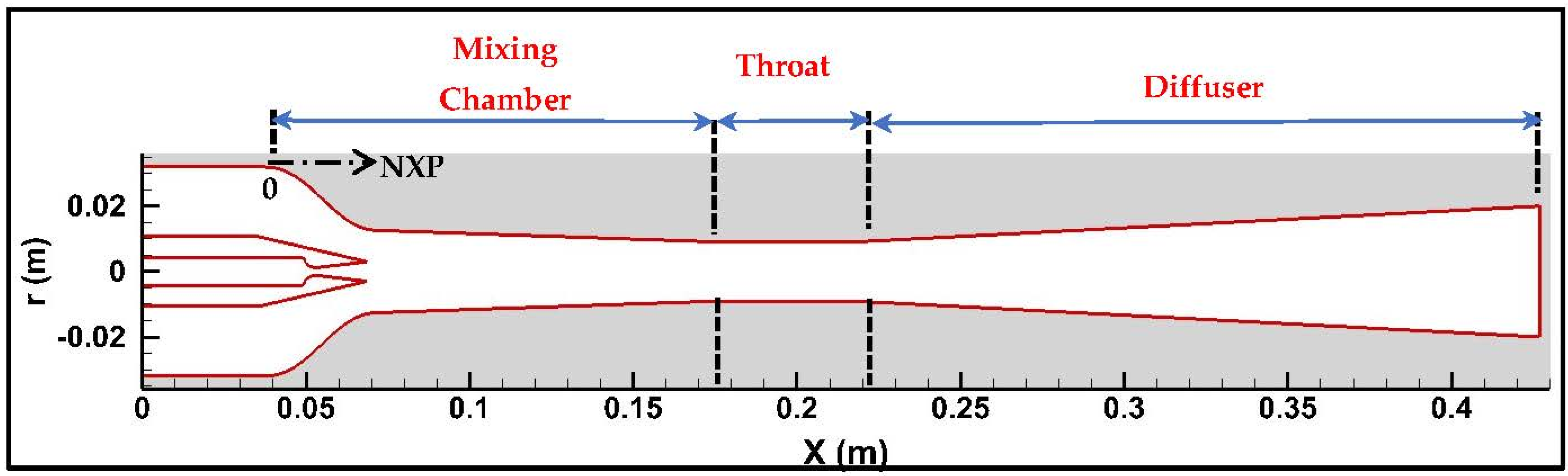
Figure 3.
Mesh structure and refinement inside the supersonic nozzle and the mixing chamber.
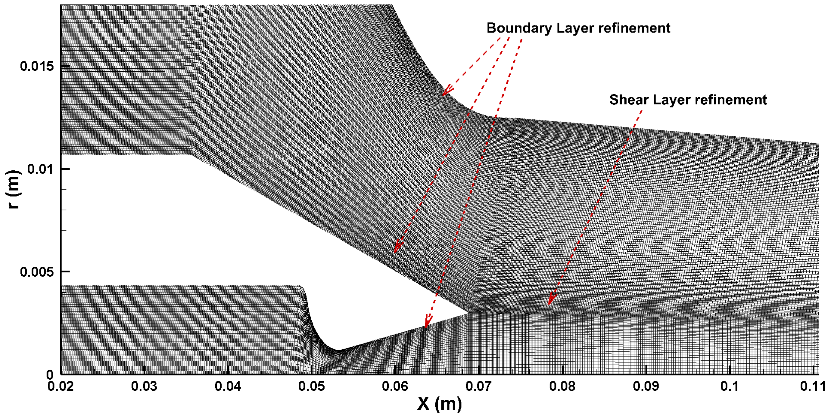
Figure 4.
Grid independence based on the convergence of the entrainment ratio.
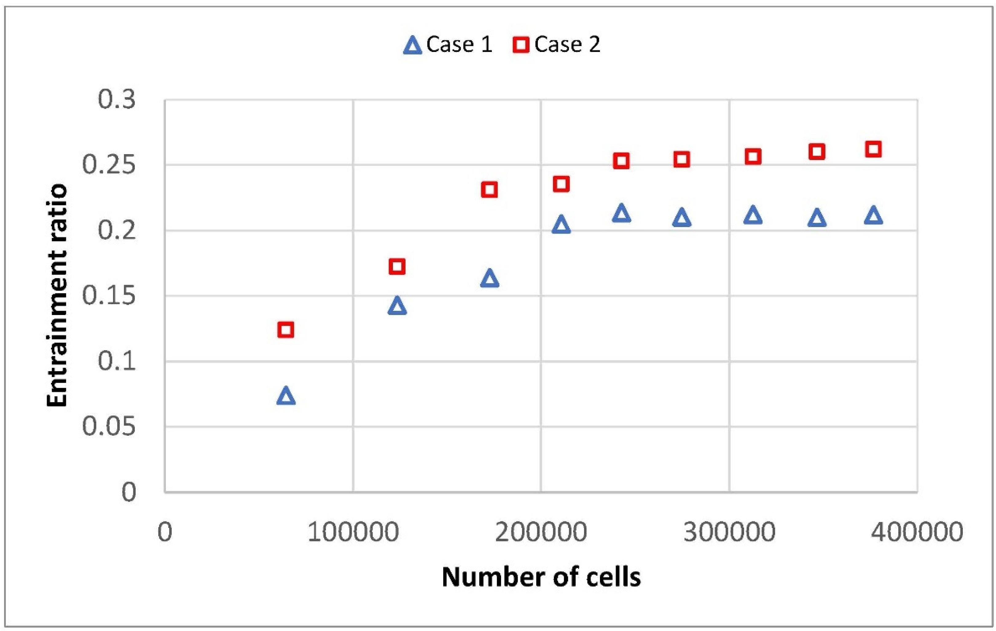
Figure 5.
Boundary conditions of the Axi-Symmetric CFD simulations.
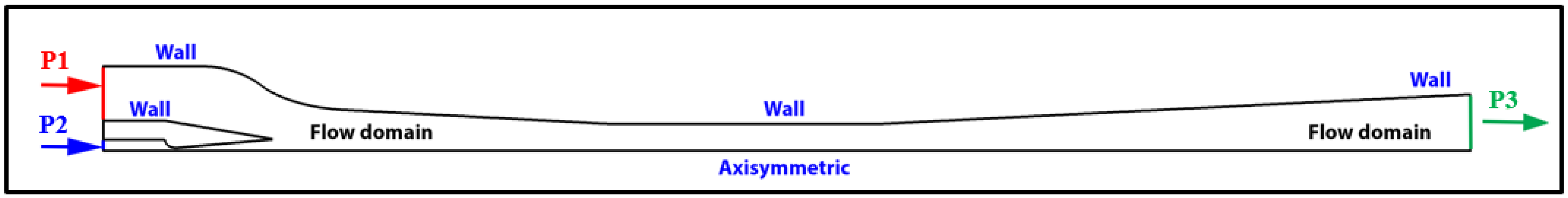
Figure 6.
fh distribution for different compression ratios (a) primary vapor pressures (b) and secondary molecular masses (c); compression ratio ranges using two fluid databases (d).
Figure 6.
fh distribution for different compression ratios (a) primary vapor pressures (b) and secondary molecular masses (c); compression ratio ranges using two fluid databases (d).
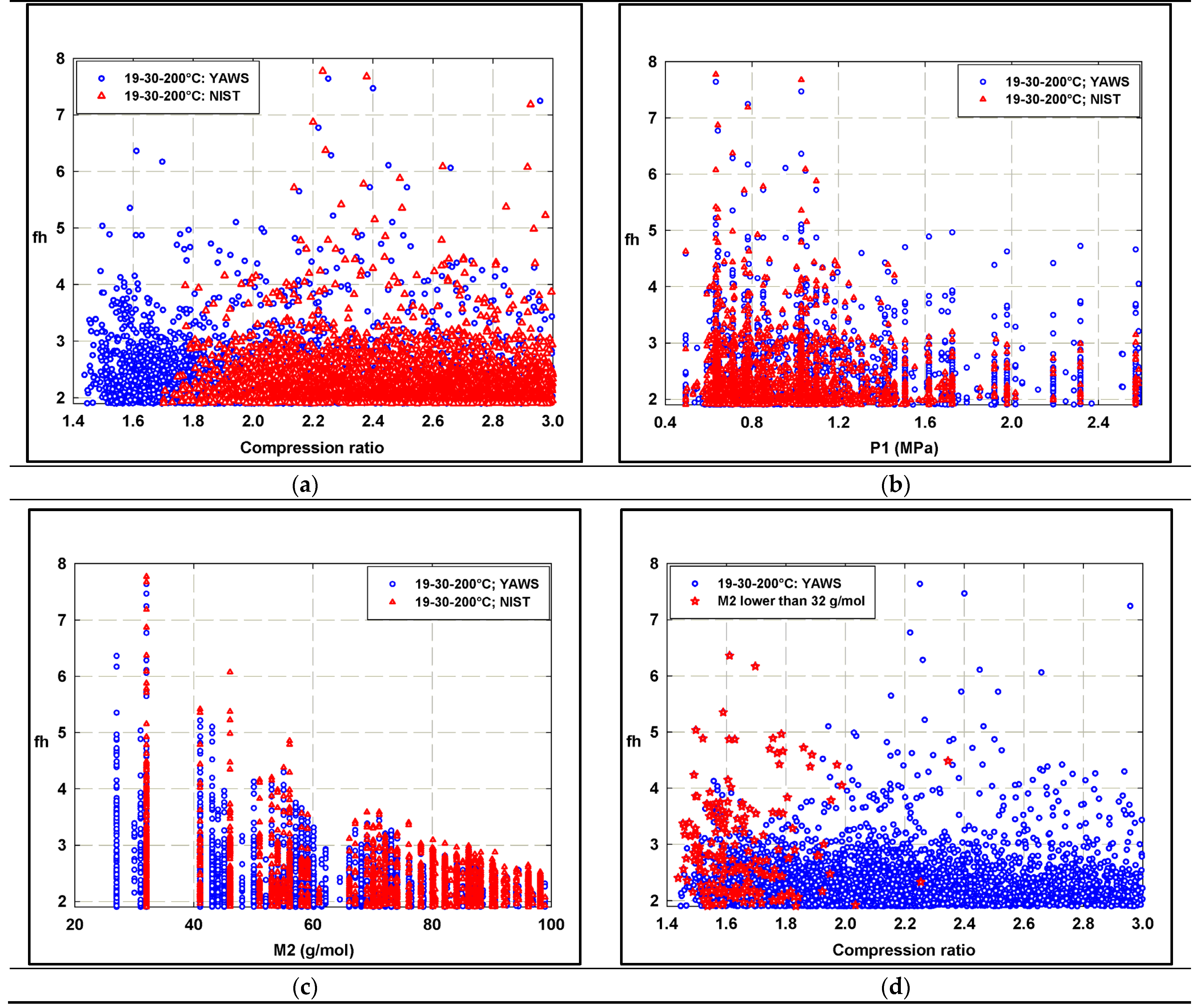
Figure 7.
Entrainment ratio prediction using CFD simulations for a single-fluid ejector.

Figure 8.
Flow dynamics inside the ejector for the difluorodiiodomethane–methanol fluid pair. (a) Methanol molar fraction and streamlines; (b) mach number and turbulent kinetic energy distributions.
Figure 8.
Flow dynamics inside the ejector for the difluorodiiodomethane–methanol fluid pair. (a) Methanol molar fraction and streamlines; (b) mach number and turbulent kinetic energy distributions.
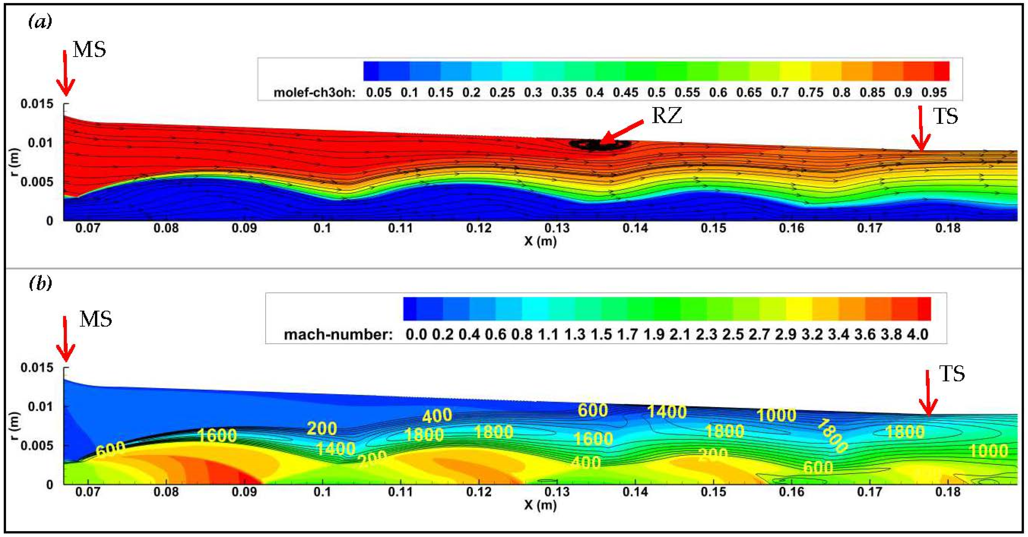
Figure 9.
Flow dynamics inside the ejector for the bromofluoroiodomethane–methanol fluid pair. (a) Methanol molar fraction and streamlines; (b) mach number and turbulent kinetic energy distributions.
Figure 9.
Flow dynamics inside the ejector for the bromofluoroiodomethane–methanol fluid pair. (a) Methanol molar fraction and streamlines; (b) mach number and turbulent kinetic energy distributions.
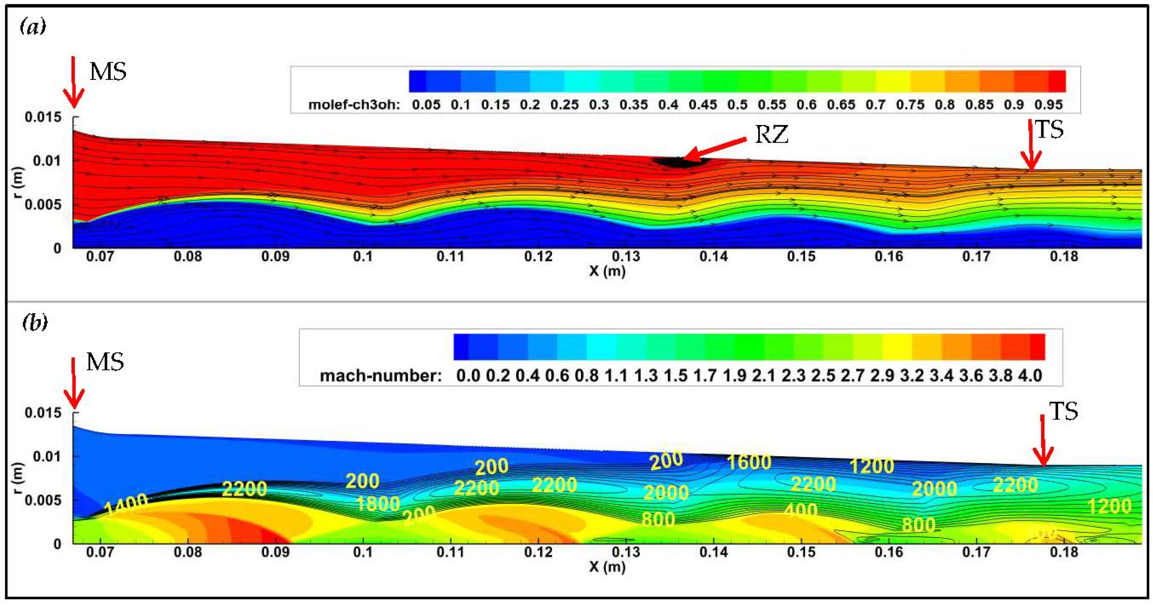
Figure 10.
Flow dynamics inside the ejector for the bromotrichloromethane–methanol fluid pair. (a) Methanol molar fraction and streamlines; (b) mach number and turbulent kinetic energy distributions.
Figure 10.
Flow dynamics inside the ejector for the bromotrichloromethane–methanol fluid pair. (a) Methanol molar fraction and streamlines; (b) mach number and turbulent kinetic energy distributions.

Table 1.
Binary fluid candidates for the BFE GSHP cooling system (19–30–200 °C). The first three fluid candidates (highlighted) correspond to the highest system performance cases.
Table 1.
Binary fluid candidates for the BFE GSHP cooling system (19–30–200 °C). The first three fluid candidates (highlighted) correspond to the highest system performance cases.
| Primary Fluid | Secondary Fluid | M1 (g/mol) | M2 (g/mol) | M1/M2 | PBoil (Mpa) | PEvap (Kpa) | PCond (Kpa) | CR | fh |
|---|---|---|---|---|---|---|---|---|---|
| difluorodiiodomethane | methanol | 304.00 | 32.04 | 9.49 | 1.03 | 12.31 | 29.10 | 2.36 | 7.68 |
| bromofluoroiodomethane | methanol | 238.83 | 32.04 | 7.45 | 0.80 | 12.31 | 27.00 | 2.19 | 6.37 |
| bromotrichloromethane | methanol | 198.00 | 32.04 | 6.18 | 0.83 | 12.31 | 28.00 | 2.27 | 4.92 |
| Chloroiodomethane | acetonitrile | 176.38 | 41.05 | 4.30 | 0.87 | 8.91 | 17.70 | 1.99 | 2.90 |
| ethylene, 1,1-dibromo | acetonitrile | 185.85 | 41.05 | 4.53 | 1.02 | 8.91 | 17.50 | 1.96 | 2.80 |
| 2-chloropropenoyl fluoride | methanol | 108.50 | 32.04 | 3.39 | 1.20 | 12.31 | 29.00 | 2.36 | 2.47 |
| 3-methylthiophene | methanol | 98.17 | 32.04 | 3.06 | 0.70 | 12.31 | 25.50 | 2.07 | 2.34 |
| methanedithiol | methanol | 80.17 | 32.04 | 2.50 | 1.20 | 12.31 | 29.00 | 2.36 | 2.12 |
| 1-methoxycyclopentene | methanol | 98.14 | 32.04 | 3.06 | 0.77 | 12.31 | 25.20 | 2.05 | 1.97 |
Table 2.
Entrainment ratio and refrigeration cycle COP for different binary fluid candidates. The first three fluid candidates (highlighted) correspond to the highest system performance cases.
Table 2.
Entrainment ratio and refrigeration cycle COP for different binary fluid candidates. The first three fluid candidates (highlighted) correspond to the highest system performance cases.
| Primary Fluid | Secondary Fluid | M1 (g/mol) | M2 (g/mol) | M1/M2 | PEvap (KPa) | PCond (KPa) | PBoil (MPa) | TBoil (°C) | CR | (g/s) | (g/s) | ER | fh | COP |
|---|---|---|---|---|---|---|---|---|---|---|---|---|---|---|
| Difluorodiiodomethane | methanol | 304.00 | 32.04 | 9.50 | 12.31 | 29.10 | 1.03 | 200 | 2.36 | 25 | 5.2 | 0.21 | 7.68 | 1.60 |
| Bromofluoroiodomethane | methanol | 238.83 | 32.04 | 7.45 | 12.31 | 27.00 | 1.00 | 220 | 2.19 | 21.1 | 5.6 | 0.26 | 6.37 | 1.69 |
| Bromotrichloromethane | methanol | 198.00 | 32.04 | 6.19 | 12.31 | 28.00 | 0.83 | 210 | 2.27 | 16.2 | 5.9 | 0.36 | 4.92 | 1.79 |
| Chloroiodomethane | acetonitrile | 176.38 | 41.05 | 4.30 | 8.90 | 17.70 | 0.70 | 180 | 1.99 | 13.3 | 4.5 | 0.34 | 3.00 | 1.02 |
| ethylene, 1,1-dibromo | acetonitrile | 185.85 | 41.05 | 4.53 | 8.90 | 17.50 | 0.70 | 170 | 1.97 | 13.7 | 4.4 | 0.32 | 2.80 | 0.90 |
| 2-chloropropenoyl fluoride | methanol | 108.50 | 32.04 | 3.39 | 12.31 | 29.00 | 1.20 | 200 | 2.36 | 17.5 | 6.4 | 0.37 | 2.36 | 0.86 |
| 3-methylthiophene | methanol | 98.17 | 32.04 | 3.06 | 12.31 | 25.50 | 0.80 | 204 | 2.07 | 10.8 | 6.3 | 0.58 | 2.34 | 1.37 |
| Methanedithiol | methanol | 80.17 | 32.04 | 2.50 | 12.31 | 29.00 | 1.20 | 200 | 2.36 | 13.3 | 7.05 | 0.53 | 2.02 | 1.07 |
| 1-methoxycyclopentene | methanol | 98.14 | 32.00 | 3.07 | 12.31 | 25.20 | 0.77 | 200 | 2.05 | 10.6 | 6.53 | 0.62 | 1.97 | 1.21 |
Publisher’s Note: MDPI stays neutral with regard to jurisdictional claims in published maps and institutional affiliations. |
© 2022 by the author. Licensee MDPI, Basel, Switzerland. This article is an open access article distributed under the terms and conditions of the Creative Commons Attribution (CC BY) license (https://creativecommons.org/licenses/by/4.0/).
Share and Cite
MDPI and ACS Style
El Hassan, M. Numerical Characterization of the Flow Dynamics and COP Estimation of a Binary Fluid Ejector Ground Source Heat Pump Cooling System. Fluids 2022, 7, 250. https://doi.org/10.3390/fluids7070250
AMA Style
El Hassan M. Numerical Characterization of the Flow Dynamics and COP Estimation of a Binary Fluid Ejector Ground Source Heat Pump Cooling System. Fluids. 2022; 7(7):250. https://doi.org/10.3390/fluids7070250
Chicago/Turabian StyleEl Hassan, Mouhammad. 2022. "Numerical Characterization of the Flow Dynamics and COP Estimation of a Binary Fluid Ejector Ground Source Heat Pump Cooling System" Fluids 7, no. 7: 250. https://doi.org/10.3390/fluids7070250