
Design and Numerical Simulation of Biomimetic Structures to Capture Particles in a Microchannel


1
Department of Mechanical and Electro-Mechanical Engineering, Tamkang University, Tamsui 251301, Taiwan
2
Department of Mechanical Engineering, Vel Tech Rangarajan Dr. Sagunthala R&D Institute of Science and Technology, Chennai 600062, India
*
Author to whom correspondence should be addressed.
Fluids 2022, 7(1), 32; https://doi.org/10.3390/fluids7010032
Submission received: 13 November 2021
/
Revised: 29 December 2021
/
Accepted: 10 January 2022
/
Published: 12 January 2022
(This article belongs to the Special Issue Recent Advances in Single and Multiphase Flows in Microchannels, Volume II)
Abstract
:The study of separating different sizes of particles through a microchannel has been an interest in recent years and the primary attention of this study is to isolate the particles to the specific outlets. The present work highly focuses on the design and numerical analysis of a microchip and the microparticles capture using special structures like corrugated dragonfly wing structure and cilia walls. The special biomimetic structured corrugated wing is taken from the cross-sectional area of the dragonfly wing and cilia structure is obtained from the epithelium terminal bronchioles to the larynx from the human body. Parametric studies were conducted on different sizes of microchip scaled and tested up in the range between 2–6 mm and the thickness was assigned as 80 µm in both dragonfly wing structure and cilia walls. The microflow channel is a low Reynolds number regime and with the help of the special structures, the flow inside the microchannel is pinched and a sinusoidal waveform pattern is observed. The pinched flow with sinusoidal waveform carries the particles downstream and induces the particles trapped in desired outlets. Fluid particle interaction (FPI) with a time-dependent solver in COMSOL Multiphysics was used to carry out the numerical study. Two particle sizes of 5 µm and 20 µm were applied, the inlet velocity of 0.52 m/s with an inflow angle of 50° was used throughout the study and it suggested that: the microchannel length of 3 mm with corrugated dragonfly wing structure had the maximum particle capture rate of 20 µm at the mainstream outlet. 80% capture rate for the microchannel length of 3 mm with corrugated dragonfly wing structure and 98% capture rate for the microchannel length of 2 mm with cilia wall structure were observed. Numerical simulation results showed that the cilia walled microchip is superior to the corrugated wing structure as the mainstream outlet can conduct most of the 20 µm particles. At the same time, the secondary outlet can laterally capture most of the 5 µm particles. This biomimetic microchip design is expected to be implemented using the PDMS MEMS process in the future.
Keywords:
microchip; microchannel; particle capture; vortex; corrugation; cilia; fluid particle interaction; COMSOL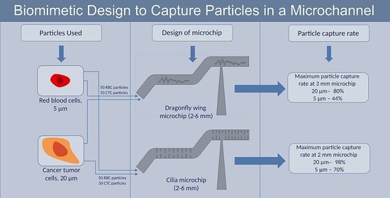
1. Introduction
Capturing and sorting of particles through microchips were the paramount interest of study in recent years. Researchers have conducted much research on separation, isolation, capture of different sizes of microparticles using a microchannel. One of the research is Sollier’s approach which makes use of micro-scale vortices and selectively separates the concentrated larger particles while smaller particles are flushed out of the device [1]. As the vortex technology is vastly used for capturing and separation of the particles through microchips.
Various techniques to capture the particles through the microchips are elaborated. Viscoelasticity-induced particle migration technique was applied to separate particles by using strong elasticity and low viscosity through simple straight microchannels [2]. Similarly, a passive microfluidic device with a spiral configuration uses inertial forces and viscous drag force for the complete separation of particles. The dominant inertial forces and Dean rotational forces in spiral microchannel cause the bigger particles to occupy a position near the wall and vice-versa to the small particles on the other side of the wall due to Dean forces [3,4]. A micro vortex manipulator (MVM) is a passive, scalable system for the separation of particles in microfluidic conditions. Helical flows are induced by topographically patterned microchannel surfaces which allow parallel streams into guiding particles and other research was done on the microfluidic vortex theory [5,6,7,8,9,10].
Another research showed that they produced two microfluidic chips based on the crossflow filtration principle and suggested that they can be more effective than conventional types and avoid clogging or jamming of particles [11]. Also, for counting, detecting, and sorting of microparticles, the sheath flow focusing and sheathless focusing theory was applied in microfluidic devices [12]. Jian et al. designed a microfluidic device that can successfully detect 6 out of 8 non-small cell lung cancer (NSCLC), and Hongmei et al. explored with micro-ellipse filters for particles and there are small tunnels which gives less chance to escape [13,14,15,16,17,18,19,20,21,22,23,24,25].
Recent works on microfluidic devices are performed to detect the tumor markers including functions like blood plasma separation, microvalve operation, and antibody immobilization [16]. Those authors used 3D printing technology to fabricate the micromixers with different shapes of barriers like cylindrical, semi-cylindrical, conical, and semi-conical. The efficiency of the cylindrical barrier was around 23.7–83.7% [17].
Ciou of the authors’ team used a double-stepped microchannel with an inclination of 60° for particle separation and capturing [18]. Corrugated dragonfly wings were implemented inside the PDMS microchannel for particle capturing applications and to replace long stretched channels compared to Sollier’s [1]. On continuation, the concept of different flow resistances in channel branches induce different flow rates which make possibilities to capture particles, a vortex-based PDMS chip was developed with a corrugated dragonfly wing for particle capture applications. In this device, only one dragonfly wing didn’t work well and needs another one in series for better performance [19]. Wang thereafter noticed that near the 2nd dragonfly wing downstream occurred a particle choking after 264 s and proposed to open a secondary outlet for cleaning function or capturing those chocked particles. The detailed representation of the dragonfly wing corrugated structure is characterized in the latter.
The overall objective of the present work is divided into two-folds: (1) to design and numerically analyze the particle capture percentages of microchips with corrugated dragonfly wing structures; (2) to investigate the particle capture percentages by replacing the dragonfly wing structures with cilia walls in the microchips. Both the above two-fold work was simulated by the fluid-particle interaction (FPI) module of COMSOL Multiphysics software.
2. Materials and Methods
In this work, the design reference was taken from [19,20,21] and modifications were done to study and test the performance of the microchip in particle capture and separation applications. In continuation, the cilia walls were employed to enhance the particle separation efficiency in the microchip design.
The microchip design for capturing particles is based on biomimetic aspects. On the corrugated dragonfly structure, the wing is structurally stabilized by folded configurations which increases the flexural rigidity. Corrugated or pleated wing cross-sections are filled with small eddy vortices which attract particles like the vortex technology approach [1] and ultimately shorten the chip size for particle capture. All the microchannel heights of the microfluidic chips were kept at 80 µm in this work.
2.1. Design of a Microchip with Corrugated Dragonfly Wing Structure
This present design is inspired by conventional design like Sollier’s long straight channel with vortex trapping as it was necessary due to that it attracts the bigger particles gradually approach near the wall surface for easier capture by wall configuration. The classical straight-line channel is more than 1.5 cm, and it will have a very large pressure drop for the external pump to drive the fluidic chip to work fine [1]. A new configuration of particle capture chip is needed to be more compact, short and pressure driving. The microchips in this work are always in contrast and less than 1 cm to behave more effectively. So, the dragonfly corrugated wing is used inside the microchannel which has the same capability to generate vortex and can capture the particles with a much smaller size. Since the corrugated dragonfly wing has a zigzag structure, and the eddy vortices are already formed inside the pleated wing grooves [20]. To make the most out of it, the authors designed the microchip much shorter for the same application. The present design comprises a 50° inclination at the inlet position to provide a better angular momentum to fluid and particles. Two corrugated dragonfly wing structures were designed inside the microchannel for capturing and separation. Soon after the 1st stage of the microchannel ends, another 50° inclination was added. This helps the particles and fluid to reaccelerate and go to the 2nd dragonfly wing structure, where particle capture and separation are going to happen. When the water-filling testing with microparticles was done, it was seen that there are lots of particles choking under the 2nd dragonfly wing as shown in Figure 1 using the PDMS MEMS process and this figure is adapted from the IEEE conference paper with the permission from author Pang-Lun Wang [21]. For removing or collecting these choked particles, one easy way is to assign outlet 2 at the same site. The design, therefore, consists of an inlet, two outlets (Outlet 1 & Outlet 2), and an interior microchannel wall as shown in Figure 2. The influence of the microchip dimension plays a secondary role in particle capture and separation in this low Reynolds flow. On account of this, the microchip length is varied between 2–6 mm, and correspondingly chord length of the dragonfly wing is increased.
The microchips were designed using AutoCAD software and CFD analysis is performed using COMSOL Multiphysics. The case is internal flow and the viscous effect on the wall dominates the flow behavior which can differentiate particles with different sizes as shown in Figure 3a. Due to the incompressible flow, a time-dependent pressure-based solver and particle tracing solver is used to perform the simulation. All the simulations are carried out for a Newtonian fluid-water with a density of 1000 kg/m3, particle density of 1040 kg/m3, and atmospheric pressure. The dynamic viscosity of the fluid is 1 × 10⁻³ Pa·s and a temperature of 20 °C is considered.
The tetrahedral mesh is applied to all the fluid-particle interactions using COMSOL Multiphysics fluid-particle interaction (FPI) module for calculating varying Reynolds number flow regimes ranging from 209–1256 for the dragonfly wing chord length of 402.5 µm to 2415 µm. The chord length of the corrugated dragonfly wing i.e., 805 µm in [19] was taken to calculate the Reynolds number it was 419 for the reference case. The total number of elements is approximately 1,100,000. The minimum and maximum mesh size assigned is 1 µm and 15 µm are shown in Figure 3b. This particular mesh size is selected because the particles have to flow through the microchannel and if the mesh size is bigger than the particle size, then the particles will easily escape and flush out.
For solving fluid-particle interactions, the governing equation for laminar fluid and particle solver is utilized. The FPI module comprises of significant solver which can solve for different boundary conditions. This model accounts for the inertial force with increment in Reynolds number, viscous force, and incompressibility. This model predicts the vortex regimes, boundary layers, and particle tracking. The following are the general equations for FPI.
For fluid flow.
For particle tracing.
Regarding selecting the particle size in the simulation and the previous filling experiment in Figure 1, it depends on the application. This simulation work is for separating two different sizes of particles herein, for the better reference we selected 20 µm as the bigger particle diameter ranges between 15–25 µm and 5 µm as the smaller particle diameter ranges from 6.2–8.2 µm) [22].
Meanwhile, the inlet velocity, equivalent to Sollier’s work [1], is selected as 0.52 m/s so as to have the corresponding Reynolds number approach to 209 and to generate good vortex patterns in the corrugated grooves [19].
Therefore, in this study, a total of 100 particles (5 µm: 50 and 20 µm: 50, 1 particle is counted as 2%) were sent with a velocity of 0.52 m/s to the microchannels of various configurations. 3D CFD analysis is performed for the microchip design with corrugated dragonfly wing patterns and its results of particle capture distribution are given in Table 1.
The particle has no option to go travel freely but the destiny is to be trapped at the assigned outlets. The particles start to flow from the inlet and the vortex strength produced by inclination angle at entrance enhances the flow and pressurizes the particles. The large particles start flowing above the dragonfly wing. The corrugated dragonfly wing actually blocks inside the microchannel and separates it into two branches. It induces different flow resistances for two branches above and below the wing, and one of the branches will finally find no flow naturally. From the particle choking experiment in Figure 1, the flow resistance of the branch above the wing is apparently smaller than the lower branch and the 20 µm particles actually follow this trend to pass through the 1st dragonfly wing and at time 0.004 s shown in Figure 4a, and the flow field of the 2nd dragonfly wing or the Outlet 1 at 0.0112 s shown in Figure 4b.
Simulation results in Table 1 show that the capture percentage at outlet 1 about the 20 µm particles ranges 72–80%, and 5 µm particle size capture percentage defined as the particle attachment sum of outlet 2 and inside the microchannel ranges 42–46%. The changing trend of the particle capture chip is minorly related to the microchannel length from 2–6 mm. Table 1 also revealed that, at a 3 mm corrugated dragonfly wing microchip, the largest particle attachment of 80% took place at outlet 1 for 20 µm particles.
Based on the observation that major bigger particles flush directly to the outlet 1 at time 0.0112 s shown in Figure 4b, at the same time, we hope the situation at outlet 2 will be similar to the particle choking in Figure 1 and is exactly composed of all smaller particles 5 µm there. However, we were disappointed to see that only 32–38% of 5 µm particles switched to outlet 2. Even we sum up the 5 µm particles at outlet 2 and inside the microchannel, even more, the percentage only ranges as fore-mentioned values of 42–46%. In other words, if we regard the whole microchannel with the corrugated dragonfly wings as a fine-particle capturer, the effective by-passing for the 20 µm particles works fine; but the capture capability for the 5 µm particles is still questionable. Assigning the corrugated dragonfly wings inside a microchannel is not the optimum way for fine particle capture.
The CFD of particle flow through the corrugated dragonfly wing microchip is shown in Figure 5. This figure shows how the particle travels inside the microchip in each section with respect to time. The velocity streamlines were also shown.
2.2. Design of a Microchip with Cilia Wall Structure
A similar vortex-based microchannel technique was to use a cilia wall microchip to replace the role of the corrugated dragonfly wings to have a better coarse particle capture percentage of more than 72–80%. We intended to go for higher particle capture at the outlets, so the next challenge was to develop an interior wall that can accelerate the fluid more and can separate and capture more particles. Since the cilia walls are present in the human body and its function is to help expel particles over the trachea, we inserted the cilia walls and designed the microchip shown in Figure 6. Cilia walls are irregular in length and when the fluid is traveled across it, the micro vortices are formed inside it, which is similar to the corrugated dragonfly wing. Both the structures are grooved, and micro vortices are generated inside the grooves which is the prime idea for our particle capture application. Using the cilia walls inside the microchannel on the top and bottom side of the microchannel wall is quite easy than the dragonfly wing structure because the cilia walls are coincident with the microchannel wall which eases the channel design and the fabrication process. Cilia walls are more in number; therefore, the number of micro vortices will be more inside the microchannel. Generally, cilia sweep fluids and foreign particles from one side to another very easily. Some scholars proposed active microfluidic mixers by using artificial cilia structures. It was seen that the artificial cilia structure can generate efficient fluid mixing inside the microchannel [23]. Chen et al. continuously enhanced the magnitude of induced 3D vortical flow pattern by cilia through the in-plane asymmetric beating for high-performance active mixing [24], or to mimic a fish-schooling distribution arrangement of artificial cilia [25]. The transient hydrodynamics induced by dynamic motions of artificial cilia also helped to identify the ideal trajectory of cilia for micro propulsion [26,27,28]. The above-mentioned artificial cilia studies inspire us to investigate the cilia design pattern in a microchannel for particle capture application. In this work, the cilia walls are considered to be rigid without active beating. COMSOL Multiphysics software was used to carry out the numerical simulation with the same conditions as the corrugated dragonfly wing.
COMSOL Multiphysics module of fluid-particle interaction (FPI) was used for calculating the varying Reynolds number flow regions. The tetrahedral mesh was applied to the cilia geometries and the number of elements is approximately 1,600,000. The minimum and maximum mesh sizes assigned are 1 µm and 15 µm. The computational domain and meshing are shown in Figure 7.
Table 2 shows that microchips with cilia walls with a capture rate of 88–98% of 20 µm at outlet 1, which is globally better than 72–80% of the performance of corrugated dragonfly wings in Table 1. Even though there are no two branches with different flow resistance right now for the cilia wall microchannel to distinguish different particle sizes, however, the shape of cilia walls presented inside the microchip is on purpose made with a longer tooth on one side and a shorter tooth on the other side. The cilia structure is arranged like the ebony and ivory of a piano. The pinched fluid inside the microchannel [29] creates a sinusoidal wavy flow motion occurred due to the cilia walls. The 20 µm particles, due to their larger inertia mass, would like to travel along the central line of the overall wavy flow until to outlet 1 shown in Figure 8.
Another better function of the microchannel with cilia wall is on the fine particle (5 µm) capture. Pinched flow with wavy flow motion along the microchannel stream is majorly contributed by the fine particle due to its smaller inertia mass. Therefore, we can have an exciting observation from Table 2: If we sum up the 5 µm particles at outlet 2 and inside the cilia microchannel in Table 2, the fine particle (5 µm) capture percentage ranges 60–70%, much better than 42–46% of the case of corrugated dragonfly wing microchannel in Table 1. The particle capture and the CFD results are shown in Figure 9.
3. Discussion
COMSOL Multiphysics fluid-particle interaction (FPI) module with time-dependent solver helped to predict the particle behavior inside the microchannel. The total flow time for particles was set to be 0.07 s but the total particles tend to separate between 0.035–0.04 s. Sollier’s vortex technology chip takes a longer time of 0.2 s to process 50 particles of 20 μm and 50 particles of 5 μm for particle capture application and the numerical simulation of the literature reference design is shown in Figure 10 and Table 3 for the validation of the study. Newtonian fluid is considered and water is selected as working fluid in this reference simulation to understand and analyze the global behavior of microchip design and its characteristics when particles are made to flow inside it. The vortex chambers in the microchannel are filled with vortices and shown in Figure 10b which tells us that the majority of the particles flow downstream with the momentum of flow. The capture rate of the bigger particles for Newtonian fluid at the outlet is 58% and 10% particles are inside the vortex chambers shown. Since it is a long straight microchannel, the particles are not fully accelerated and slowly reach the downstream. In the real case, the water consists of millions of particles; many particles will flow downstream and some particles will stick inside the microchannel. It is impossible to enumerate the size of particles accurately. We can only predict the majority of particles flushing to the preferred outlets. So, we used 50 particles of 20 μm and 50 particles of 5 μm to enumerate it easily, if more particles are present as a real case, it will be impossible to find out the correct size of the particle at each outlet. Subsequently, the aim was to reduce the chip size and control the fluid momentum according to the application and the primary interest was to obtain a higher particle capture rate at desired outlets. Sollier in his original study used non-Newtonian fluid and we can’t compare the real efficiency, so we used Newtonian fluid for overall microchip designs and numerically simulated it. In this present study, we showed the COMSOL model for microchips with Newtonian fluid and analyzed the global and local behavior of particles.
While our present cilia walled microchip with very small dimensions can do the same job rapidly (0.035–0.04 s) and efficiently with a lower flow rate of the fluid. This phenomenon occurs as the flow becomes fully accelerated with the inclination of 50° at the inlet section of the microchannel and the flow momentum when reaching near the corrugated dragonfly wings or cilia walls with biomimetic features, is already more agitated. So, different outlets would like to harvest the particles with their favorite size.
Looking at the corrugated dragonfly wing generally, it seems to be less aerodynamic, but when doing the CFD and analyzing, the grooves are filled with vortices and the fluid tries to flow past it. This structure eventually creates the conventional airfoil and creates the pressure region which allows the particle to go with the momentum. Adding one more microchannel with 50° inclination and corrugated dragonfly wing after the 1st microchannel, further accelerated the flow, and the particles that are already detached get additional separation and capture at the outlets. Two stages of microchannels were effective in separating and capturing the particles as shown in Figure 11. The flow velocity tends to accelerate after it reaches the low-pressure zone and the maximum velocity reaches around 2.5 m/s. Bigger particles like to go along the branch with lower flow resistance, i.e., the mainstream of the whole microchannel until outlet 1. Due to the large momentum of the bigger particles, they would like to follow the mainstream direction with a small lateral deviation. On the other hand, the smaller particles with less momentum may have more apparent lateral deviation and are apt to be captured by the wall surface and the second branch to outlet 2. It doesn’t mean that the smaller particles must go through the branch with higher flow resistance (to outlet 2) rather than the branch with lower flow resistance (to outlet 1.) This design concept herein only reminds us that, if we adopt some proper patterns inside the microchannel to create major/secondary branches, we may obtain a better capture percentage for the smaller particles from the mainstream. Eventually, we get the particle capture and separation effect at outlets.
The local flow path at the corrugated dragonfly wing microchip structure shown in Figure 4 reveals that the lower flow resistance above the wing structure takes the bigger particles to outlet 1. The different flow resistance separates bigger particles to the top of the dragonfly wing which is directly downstream from the outlet. Figure 4 clearly shows the inclination in the microchip entrance creates the acceleration and conveys the bigger particle to the lower flow resistance area.
Another interesting thing we can see from the 3D image CFD results in the dragonfly wing microchip is the particle bouncing through the wall and making a spiral flow after hitting each wall. The particles don’t travel in a straight manner, it is rotated and twisted like a spiral with the flow. From the zoom-in view of Figure 12, we can see that the streamlines are ended inside the corrugated structure after reaching their destiny. Thus, by multiple streamlines after the vortex generation and spiral flow, the particles compatibly travel with the flow to the downstream.
In the case of the microchip with cilia walls, the dragonfly wing structure is replaced by cilia walls inside the microchannel. The primary function of cilia is to sweep the fluids and foreign particles to another side. Generally, the size of cilia is irregular, and it is flexible. We have considered cilia as rigid walls inside the microchannel because after the microchip fabrication using PDMS, it won’t be flexible. Considering the cilia wall length, the same dimensions of small and big cilia walls are maintained with the same aspect ratio. If the top side of the microchannel consists of big cilia, then the bottom side will consist of a small cilia wall, and it follows the pattern throughout the straight path of the microchannel. By maintaining this unique pattern and with a 50° inclination at the inlet, we can see the pinched flow is now in a sinusoidal waveform inside the microchannel with the help of cilia walls. Each groove inside the cilia walls is now filled with micro vortices and is shown in Figure 13. The number of vortices is much more in the cilia wall microchip in Figure 13b compared to the corrugated dragonfly wing microchip. Now, cilia walls take account of the fluid and particles. Similar to the previous design, another stage of the microchannel with 50° inclination was included to augment the separation and capture of particles. By looking closely at the velocity streamline, we can notice that the flow follows a sinusoidal function as the cilia walls direct the flow in such pattern and momentum.
Looking at Figure 13a with fewer streamlines, it is clear that the flow velocity is lesser at the cilia edges after the vortices filled inside the grooves and the flow velocity is higher in the center of the streamlines. This allows the wavy flow’s higher momentum region to take the bigger particles to an outlet and let the lower momentum region take the smaller particles to another outlet. Figure 8a demonstrates that the particle in the first half of the microchannel is accelerated with the inclination and by narrowing the throat of the microchannel by using cilia walls, we are pushing the particles into the cilia wall microchannel where we manually turn the flow into wavy and that induces the bigger particles to flow in the higher momentum region and small particles into the lower momentum region. In the case of Figure 8b, the outlet 2 opening looks respectable for smaller particles to be trapped or guided into outlet 2, while the bigger particles tend to flow downstream. In this way, we can conduct the particles in respected outlets or make the particles stay inside the microchannel to attain a capture rate of around 62–70%.
Similar to the case of the corrugated dragonfly wing microchip; the cilia wall microchip also exhibited a similar state of particles and streamlines. Figure 14 shows that the streamlines are not straight, it travels in a spiral motion and creates a vortex inside the cilia wall gaps. Streamlines are ended here too after being converted into the vortex and reaching its destiny. By making the particles move in a spiral way is useful as it can delay the particle travel time downstream and also it can help to redirect the particles in the preferred outlet.
In summary, the low Reynolds flow herein is hard to be chaotic in general and bad to be separated about particles with different sizes. We basically keep the larger momentum particles downstream to the outlet directly but tried to agitate the flow more laterally by two 50° flow declination. How to design the biomimetic patterns inside the microchannel is the key to enhancing the small particle capture rate. For the dragonfly wing channel, the vortex effect inside the dragonfly wing corrugation is very limited; whereas for the cilia channel design much more vortex effectively produces apparent wavy agitation so as to increase the small particle capture rate. Finally, an overall comparison is shown in Table 4 subjected to Sollier’s chip design for ease of understanding the advantages of microchip design in this work. Using Poiseuille’s law, it is possible to calculate the driving pressure inside the microchannel.
Poiseuille’s law,
where, Volumetric flow, Q = UA. µ is the dynamic viscosity of the fluid. r = Dh (Hydraulic diameter). L is the length of the microchannel.
Restated, the corrugated dragonfly wing had the highest capture rate of 80% at outlet 1 on 20 µm particle size and 46% of 5 µm particle size at outlet 2 and inside microchannel in 3 mm microchip with a processing time of 0.04 s and has a driving pressure of 17,340 Pa. While it was observed that the cilia wall microchip had an extraordinary capture rate of 98% of 20 µm particle size at outlet 1 and 70% of 5 µm at outlet 2 and inside microchannel in 2 mm microchip with a processing time of 0.0224 s and has a driving pressure value of 35,564 Pa. Both dragonfly wings and cilia wall chips consist of two outlets and the particle capture rate of 20 µm is higher at outlet 1 and it is better for bypassing bigger particles. The inner structures of dragonfly wing and cilia walls are placed in such a way that most of the bigger particles will reach the downstream or outlet 1. The higher the percentage of 20 µm particles at outlet 1 means good filtering of them at outlet 2. Therefore, this capture mechanism would work well at outlet 2 for 5 µm particles. On the contrary, Sollier’s chip design does not have outlet 2. Both 5 µm and 20 µm particles have only way to go to outlet 1, which only denote the imperfection of its capture function. As most of the particles will flow downstream and a less percentage of particles will be captured inside the vortex chamber shown in Figure 10 and Table 3. This implies that the higher percentage of both sizes of particles is not good for bypass or capture effect.
This research mainly shows the study of Newtonian fluid and the simulations are carried out to find out the global behavior inside the microchannel and its characteristics. In the real case for experimental verification, it is very difficult to enumerate the particles count as the working fluid consists of millions of particles. So, to identify the particle trajectory, we have assigned 50 particles of 20 μm and 50 particles of 5 μm to enumerate and easily. We focused on COMSOL model simulation of microchips with Newtonian fluid which shows better results after shortening the size while compared to Sollier’s design. In the future, the microchips with cilia walls are expected to be fabricated using PDMS and tested in various particle capture and separation field such as air filters, face masks [30], and so on.
4. Conclusions
The microchips were designed and simulated with corrugated dragonfly wing and cilia walls inside the microchannel using COMSOL Multiphysics fluid-particle interaction (FPI) module with a time-dependent solver. The inclination of 50° bettered the pinching of flow and make the fluid more effective. The special structures generated the vortices well inside the microchannel which helped the respective particles to move to their outlets. The size of the microchip is effectively reduced by 10 times and the processing time was only 0.035–0.04 s. The cilia wall microchip had an extraordinary capture rate of 98% of 20 µm particle size at the downstream outlet and 70% of 5 µm at the secondary outlet with a driving pressure drop of 35,564 Pa only.
The low-Reynolds microchannel flow herein is hard to be chaotic in general and bad to be separated about particles with different sizes. We designed the biomimetic patterns to agitate the flow more wavily and oscillate laterally so as to increase the chance for smaller particles to be trapped and the bigger particles to be conducted downstream. The final comparison to Soiller’s chip design revealed our design’s compact size and higher particle capture rate.
Author Contributions
Conceptualization, L.-J.Y.; methodology, L.-J.Y.; software, V.-J.J. and N.-K.U.; validation, L.-J.Y., V.-J.J. and N.-K.U.; formal analysis, L.-J.Y., B.E. and V.-J.J.; investigation, L.-J.Y., V.-J.J., N.-K.U. and B.E.; resources, L.-J.Y.; data curation, V.-J.J. and N.-K.U.; writing—original draft preparation, V.-J.J.; writing—review and editing, L.-J.Y., V.-J.J., N.-K.U. and B.E.; visualization, V.-J.J. and N.-K.U.; supervision, L.-J.Y. and B.E.; project administration, L.-J.Y.; funding acquisition, L.-J.Y. All authors have read and agreed to the published version of the manuscript.
Funding
This research was funded by the Ministry of Science and Technology, Taiwan; grant numbers of 105-2221-E-032-009, 109-2221-E-032-002-MY2 and 109-2221-E-032-001-MY3.
Institutional Review Board Statement
Not applicable.
Informed Consent Statement
Not applicable.
Data Availability Statement
Not applicable.
Conflicts of Interest
The authors declare no conflict of interest.
References
- Sollier, E.; Go, D.E.; Che, J.; Gossett, D.R.; O’Byrne, S.; Weaver, W.M.; Kummer, N. Size-selective collection of circulating tumor cells using Vortex technology. Lab Chip 2014, 14, 63–77. [Google Scholar] [CrossRef] [PubMed]
- Liu, C.; Xue, C.; Chen, X.; Shan, L.; Tian, Y.; Hu, G. Size-based separation of particles and cells utilizing viscoelastic effects in straight microchannels. Anal. Chem. 2015, 87, 6041–6048. [Google Scholar] [CrossRef] [PubMed] [Green Version]
- Bhagat, A.A.S.; Kuntaegowdanahalli, S.S.; Papautsky, I. Continuous particle separation in spiral microchannels using dean flows and differential migration. Lab Chip 2008, 8, 1906–1914. [Google Scholar] [CrossRef]
- Shiriny, A.; Bayareh, M. Inertial focusing of CTCs in a novel spiral microchannel. Chem. Eng. Sci. 2021, 229, 116102. [Google Scholar] [CrossRef]
- Hsu, C.H.; Carlo, D.D.; Chen, C.; Irimia, D.; Toner, M. Microvortex for focusing, guiding and sorting of particles. Lab Chip 2008, 8, 2128–2134. [Google Scholar] [CrossRef] [Green Version]
- Bhagat, A.A.S.; Bow, H.; Hou, H.W.; Tan, S.J.; Han, J.; Lim, C.T. Microfluidics for cell separation. Med. Biol. Eng. Comput. 2020, 48, 999–1014. [Google Scholar] [CrossRef]
- Tang, W.; Jiang, D.; Li, Z.; Zhu, L.; Shi, J.; Yang, J.; Xiang, N. Recent advances in microfluidic cell sorting techniques based on both physical and biochemical principles. Electrophoresis 2019, 40, 930–954. [Google Scholar] [CrossRef]
- Geissler, M.; Voisin, B.; Veres, T. Air stream-mediated vortex agitation of microlitre entities on a fluidic chip. Lab Chip 2011, 11, 1717–1720. [Google Scholar] [CrossRef] [Green Version]
- Haddadi, H.; Naghsh-Nilchi, H.; Carlo, D.D. Separation of cancer cells using vortical microfluidic flows. Biomicrofluidics 2018, 12, 014112. [Google Scholar] [CrossRef]
- Haller, A.; Spittler, A.; Brandhoff, L.; Zirath, H.; Puchberger-Enengl, D.; Keplinger, F.; Vellekoop, M.J. Microfluidic vortex enhancement for on-chip sample preparation. Micromachines 2015, 6, 239–251. [Google Scholar] [CrossRef] [Green Version]
- Chen, X.; Liu, C.C.; Li, H. Microfluidic chip for blood cell separation and collection based on crossflow filtration. Sens. Actuators B Chem. 2008, 130, 216–221. [Google Scholar] [CrossRef]
- Xuan, X.; Zhu, J.; Church, C. Particle focusing in microfluidic devices. Microfluid. Nanofluidics 2010, 9, 1–16. [Google Scholar] [CrossRef]
- Zhou, J.; Kulasinghe, A.; Bogseth, A.; O’Byrne, K.; Punyadeera, C.; Papautsky, I. Isolation of circulating tumor cells in non-small-cell-lung-cancer patients using a multi-flow microfluidic channel. Microsyst. Nanoeng. 2019, 5, 1–12. [Google Scholar] [CrossRef] [PubMed] [Green Version]
- Chen, H.; Cao, B.; Sun, B.; Cao, Y.; Yang, K.; Lin, Y.S. Highly-sensitive capture of circulating tumor cells using micro-ellipse filters. Sci. Rep. 2017, 7, 610. [Google Scholar] [CrossRef]
- Wang, X.; Zhou, J.; Papautsky, I. Vortex-aided inertial microfluidic device for continuous particle separation with high size-selectivity, efficiency, and purity. Biomicrofluidics 2013, 7, 044119. [Google Scholar] [CrossRef] [Green Version]
- Sun, C.; You, H.; Gao, N.; Chang, J.; Gao, Q.; Xie, Y.; Xie, Y.; Xu, R.X. Design and fabrication of a microfluidic chip to detect tumor markers. RSC Adv. 2020, 10, 39779–39785. [Google Scholar] [CrossRef]
- Hosseini, F.; Rahimi, M. Computational fluid dynamics and experimental investigations on liquid–liquid mass transfer in T-type microchannels with different mixing channel barrier shapes. Sep. Sci. Technol. 2020, 55, 3502–3516. [Google Scholar] [CrossRef]
- Ciou, J.S. New Vortex-Based Flow Chips to Capture Particles. Master’s Thesis, Mechanical and Electromechanical Engineering, Tamkang University, Tamkang, Taiwan, 2016. [Google Scholar]
- Wang, P.L.; Ciou, J.S.; Yang, L.J.; Chung, Y.C.; Kapri, N.; Esakki, B. A new vortex-based device using dragonfly wing to reduce the chip size. In Proceedings of the 12th IEEE International Conference on Nano/Micro Engineered and Molecular Systems (NEMS), Los Angeles, CA, USA, 9–11 April 2017; pp. 81–84. [Google Scholar]
- Yang, L.J.; Kapri, N.; Waikhom, R.; Unnam, N.K. Fabrication, Aerodynamic Measurement and Performance Evaluation of Corrugated Flapping Wings. J. Aeronaut. Astronaut. Aviat 2021, 53, 83–94. [Google Scholar] [CrossRef]
- Wang, P.L. Design of a Reusable Particle-Captured Microchannel with Dual Dragonfly Wings. Master’s Thesis, Mechanical and Electromechanical Engineering, Tamkang University, Tamkang, Taiwan, 2018. [Google Scholar]
- Hao, S.J.; Wan, Y.; Xia, Y.Q.; Zou, X.; Zheng, S.Y. Size-based separation methods of circulating tumor cells. Adv. Drug Deliv. Rev. 2018, 125, 3–20. [Google Scholar] [CrossRef]
- Den Toonder, J.; Bos, F.; Broer, D.; Filippini, L.; Gillies, M.; de Goede, J.; Mol, T.; Reijme, M.; Talen, W.; Wilderbeek, H.; et al. Artificial cilia for active micro-fluidic mixing. Lab Chip 2008, 8, 533–541. [Google Scholar] [CrossRef]
- Chen, C.Y.; Lin, C.Y.; Hu, Y.T. Inducing 3D vortical flow patterns with 2D asymmetric actuation of artificial cilia for high-performance active micromixing. Exp. Fluids 2014, 55, 1765. [Google Scholar] [CrossRef]
- Chen, C.Y.; Lin, C.Y.; Hu, Y.T.; Cheng, L.Y.; Hsu, C.C. Efficient micromixing through artificial cilia actuation with fish-schooling configuration. Chem. Eng. J. 2015, 259, 391–396. [Google Scholar] [CrossRef]
- Chen, C.Y.; Hsu, C.C.; Mani, K.; Panigrahi, B. Hydrodynamic influences of artificial cilia beating behaviors on micromixing. Chem. Eng. Process. Process Intensif. 2016, 99, 33–40. [Google Scholar] [CrossRef]
- Wu, Y.A.; Panigrahi, B.; Chen, C.Y. Hydrodynamically efficient micropropulsion through a new artificial cilia beating concept. Microsyst. Technol. 2017, 23, 5893–5902. [Google Scholar] [CrossRef]
- Chen, C.Y.; Cheng, L.Y.; Hsu, C.C.; Mani, K. Microscale flow propulsion through bioinspired and magnetically actuated artificial cilia. Biomicrofluidics 2015, 9, 034105. [Google Scholar] [CrossRef] [PubMed] [Green Version]
- Nakashima, M.; Yamada, M.; Seki, M. Pinched flow fractionation (PFF) for continuous particle separation in a microfluidic device. In Proceedings of the 17th IEEE International Conference on Micro Electro Mechanical Systems. Maastricht MEMS 2004 Technical Digest, Maastricht, The Netherlands, 25–29 January 2004; pp. 33–36. [Google Scholar]
- Unnam, N.K.; Yang, L.J.; Joseph, V.J.A.; Chang, P.Z. A transparent face mask with microchannel against virus via aerosol. In Proceedings of the 25th International Conference on Miniaturized Systems for Chemistry and Lift Sciences (μTAS 2021), Palm Springs, CA, USA, 10–14 October 2021. [Google Scholar]
Figure 1.
Choking of micro-silica microspheres applied to flow channels of different configurations. (a) Single wing; (b) Stepwise-cascaded wings; (c) In-series cascaded wings. Adapted with permission from [21]. Copyright Year: 16 November 2022. Copyright Owner: Pang-Lun Wang, License number: 5190600500280.

Figure 2.
Microchip channel design with corrugated dragonfly wing patterns inside.

Figure 3.
Corrugated dragonfly wing microchip: (a) Computational domain; (b) Computational domain meshing.
Figure 3.
Corrugated dragonfly wing microchip: (a) Computational domain; (b) Computational domain meshing.

Figure 4.
Corrugated dragonfly wing microchip’s streamlines and particle view; (a) Particle trajectory at the 1st dragonfly wing at time 0.004 s; (b) Particle trajectory at the 2nd dragonfly wing or the Outlet 1 at 0.0112 s.
Figure 4.
Corrugated dragonfly wing microchip’s streamlines and particle view; (a) Particle trajectory at the 1st dragonfly wing at time 0.004 s; (b) Particle trajectory at the 2nd dragonfly wing or the Outlet 1 at 0.0112 s.

Figure 5.
Fluid-particle interaction results of corrugated dragonfly wing microchip at 0–0.04 s and velocity streamline: (a) 0 s; (b) 0.01 s, (c) 0.02 s; (d) 0.03 s; (e) 0.04 s; (f) Velocity streamlines.
Figure 5.
Fluid-particle interaction results of corrugated dragonfly wing microchip at 0–0.04 s and velocity streamline: (a) 0 s; (b) 0.01 s, (c) 0.02 s; (d) 0.03 s; (e) 0.04 s; (f) Velocity streamlines.

Figure 6.
Design of microchips with cilia walls.

Figure 7.
Cilia microchip: (a) Computational domain; (b) Computational domain meshing.

Figure 8.
Particles traveling in cilia wall microchip at: (a) 1st microchannel with cilia walls at time 0.004 s; (b) 2nd microchannel with cilia walls at time 0.0112 s.
Figure 8.
Particles traveling in cilia wall microchip at: (a) 1st microchannel with cilia walls at time 0.004 s; (b) 2nd microchannel with cilia walls at time 0.0112 s.

Figure 9.
Fluid-particle interaction results of cilia microchip at 0–0.021 s and velocity streamline: (a) 0 s; (b) 0.003 s, (c) 0.005 s; (d) 0.007 s; (e) 0.021 s; (f) Velocity streamlines.
Figure 9.
Fluid-particle interaction results of cilia microchip at 0–0.021 s and velocity streamline: (a) 0 s; (b) 0.003 s, (c) 0.005 s; (d) 0.007 s; (e) 0.021 s; (f) Velocity streamlines.

Figure 10.
Numerical simulation of Sollier’s microchip [1]. (a) Dimensions the geometry; (b) Velocity streamlines inside microchip.
Figure 10.
Numerical simulation of Sollier’s microchip [1]. (a) Dimensions the geometry; (b) Velocity streamlines inside microchip.

Figure 11.
Velocity streamlines in dragonfly wing microchip.

Figure 12.
3D view of corrugated dragonfly wing microchip at 0.004 s.

Figure 13.
Velocity streamline in cilia wall microchip: (a) 100 streamlines; (b) 500 streamlines.

Figure 14.
3D view of cilia wall microchips at 0.004 s.


Table 1.
Particle capture distribution in various corrugated dragonfly wing microchips.
| Size of Microchip | Particle Size | Outlet 1 | Outlet 2 | Inside Microchannel |
|---|---|---|---|---|
| 2 mm | 5 µm | 56% | 32% | 12% |
| 20 µm | 76% | 0 | 24% | |
| 3 mm | 5 µm | 56% | 32% | 12% |
| 20 µm | 80% | 16% | 4% | |
| 4 mm | 5 µm | 58% | 36% | 6% |
| 20 µm | 74% | 18% | 8% | |
| 5 mm | 5 µm | 56% | 38% | 6% |
| 20 µm | 76% | 20% | 4% | |
| 6 mm | 5 µm | 54% | 36% | 10% |
| 20 µm | 72% | 22% | 6% |
Table 2.
Particle capture in various cilia walls microchip.
| Size of Microchip | Particle Size | Outlet 1 | Outlet 2 | Inside Microchannel |
|---|---|---|---|---|
| 2 mm | 5 µm | 30% | 58% | 12% |
| 20 µm | 98% | 0% | 2% | |
| 3 mm | 5 µm | 32% | 58% | 10% |
| 20 µm | 96% | 0% | 4% | |
| 4 mm | 5 µm | 36% | 54% | 10% |
| 20 µm | 88% | 10% | 2% | |
| 5 mm | 5 µm | 38% | 58% | 4% |
| 20 µm | 92% | 4% | 4% | |
| 6 mm | 5 µm | 36% | 62% | 2% |
| 20 µm | 98% | 0% | 2% |
Table 3.
Particle capture rate of Sollier’s design.
| Size of Microchip | Particle Size | Vortex Chambers | Inside Microchannel | Outlet |
|---|---|---|---|---|
| 17.5 mm | 5 µm | 10% | 2% | 88% |
| 20 µm | 28% | 14% | 58% |
Table 4.
Microchip performance subjected to Sollier’s design.
| Sollier [1] | Dragonfly Wing | Cilia | |
|---|---|---|---|
| Total size of microchip | 17.5 mm | 3 mm | 2 mm |
| Driving pressure | 185,695 Pa | 17,340 Pa | 35,564 Pa |
| Maximum filtering/separation performance index of bigger particles at outlet 1 | 58% | 80% | 98% |
| Maximum filtering/separation performance index of smaller particles at outlet 1 | 88% | 56% | 30% |
| Maximum filtering/separation performance index of smaller particles at outlet 2 | - | 46% | 70% |
Publisher’s Note: MDPI stays neutral with regard to jurisdictional claims in published maps and institutional affiliations. |
© 2022 by the authors. Licensee MDPI, Basel, Switzerland. This article is an open access article distributed under the terms and conditions of the Creative Commons Attribution (CC BY) license (https://creativecommons.org/licenses/by/4.0/).
Share and Cite
MDPI and ACS Style
Yang, L.-J.; Joseph, V.-J.; Unnam, N.-K.; Esakki, B. Design and Numerical Simulation of Biomimetic Structures to Capture Particles in a Microchannel. Fluids 2022, 7, 32. https://doi.org/10.3390/fluids7010032
AMA Style
Yang L-J, Joseph V-J, Unnam N-K, Esakki B. Design and Numerical Simulation of Biomimetic Structures to Capture Particles in a Microchannel. Fluids. 2022; 7(1):32. https://doi.org/10.3390/fluids7010032
Chicago/Turabian StyleYang, Lung-Jieh, Vivek-Jabaraj Joseph, Neethish-Kumar Unnam, and Balasubramanian Esakki. 2022. "Design and Numerical Simulation of Biomimetic Structures to Capture Particles in a Microchannel" Fluids 7, no. 1: 32. https://doi.org/10.3390/fluids7010032