Article

Scaling, Complexity, and Design Aspects in Computational Fluid Dynamics

McCoy School of Engineering, Midwestern State University, Texas Tech University System, 3410 Taft Blvd., Wichita Falls, TX 76310, USA
Fluids 2021, 6(10), 362; https://doi.org/10.3390/fluids6100362
Submission received: 31 August 2021 / Revised: 24 September 2021 / Accepted: 8 October 2021 / Published: 12 October 2021
(This article belongs to the Special Issue Scientific Computing in Fluids)

Abstract

:
With the availability of more and more efficient and sophisticated Computational Fluid Dynamics (CFD) tools, engineering designs are also becoming more and more software driven. Yet, the insights in temporal and spatial scaling issues are still with us and very often imbedded in complexity and many design aspects. In this paper, with a revisit to a so-called leakage issue in sucker rod pumps prevalent in petroleum industries, the author would like to demonstrate the need to use perturbation approaches to circumvent the multi-scale challenges in CFD with extreme spatial aspect ratios and temporal scales. In this study, the gap size between the outer surface of the plunger and the inner surface of the barrel is measured with a mill (one thousandth of an inch) whereas the plunger axial length is measured with inches or even feet. The temporal scales, namely relaxation times, are estimated with both expansions in Bessel functions for the annulus flow region and expansions in Fourier series when such a narrow circular flow region is approximated with a rectangular one. These engineering insights derived from the perturbation approaches have been confirmed with the use of full-fledged CFD analyses with sophisticated computational tools as well as experimental measurements. With these confirmations, new perturbation studies on the sucker rod leakage issue with eccentricities have been presented. The volume flow rate or rather leakage due to the pressure difference is calculated as a quadratic function with respect to the eccentricity, which matches with the early prediction and publication with comprehensive CFD studies. In short, a healthy combination of ever more powerful modeling tools along with the physics, mathematics, and engineering insights with dimensionless numbers and classical perturbation approaches may provide a balanced and more flexible and efficient strategy in complex engineering designs with the consideration of parametric and phase spaces.

1. Introduction

In oil industry, artificial lift methods are often utilized to transfer the oil and gas from the formation to the surface, especially during the later phase of a petroleum reservoir’s productive life due to the diminishing fluid pressure [1]. Sucker rod pumping systems are among the most popular and low cost artificial lift means with their simple hydraulic pumping designs [2,3]. As one of the earliest inventions for oil industries, sucker rod pumping systems have been studied extensively [4,5]. Over 80 % of the wells world wide still depend on this oldest and most extensively used mechanism [6,7]. Yet, despite of their extended history and popularity, many engineering and operational issues still exist [8,9,10]. Despite the effectiveness and efficiency of this seemingly simple pumping mechanism amply demonstrated over decades [11,12], in practice, it has been reported that the leakage is related to the clearance C, or rather two times the gap δ , defined as the difference between the inner diameter of the barrel D b and the outer diameter of the plunger D a [13,14]. It is widely reported that large clearances often cause significant leakage which often renders the entire sucker rod pump systems inefficient.
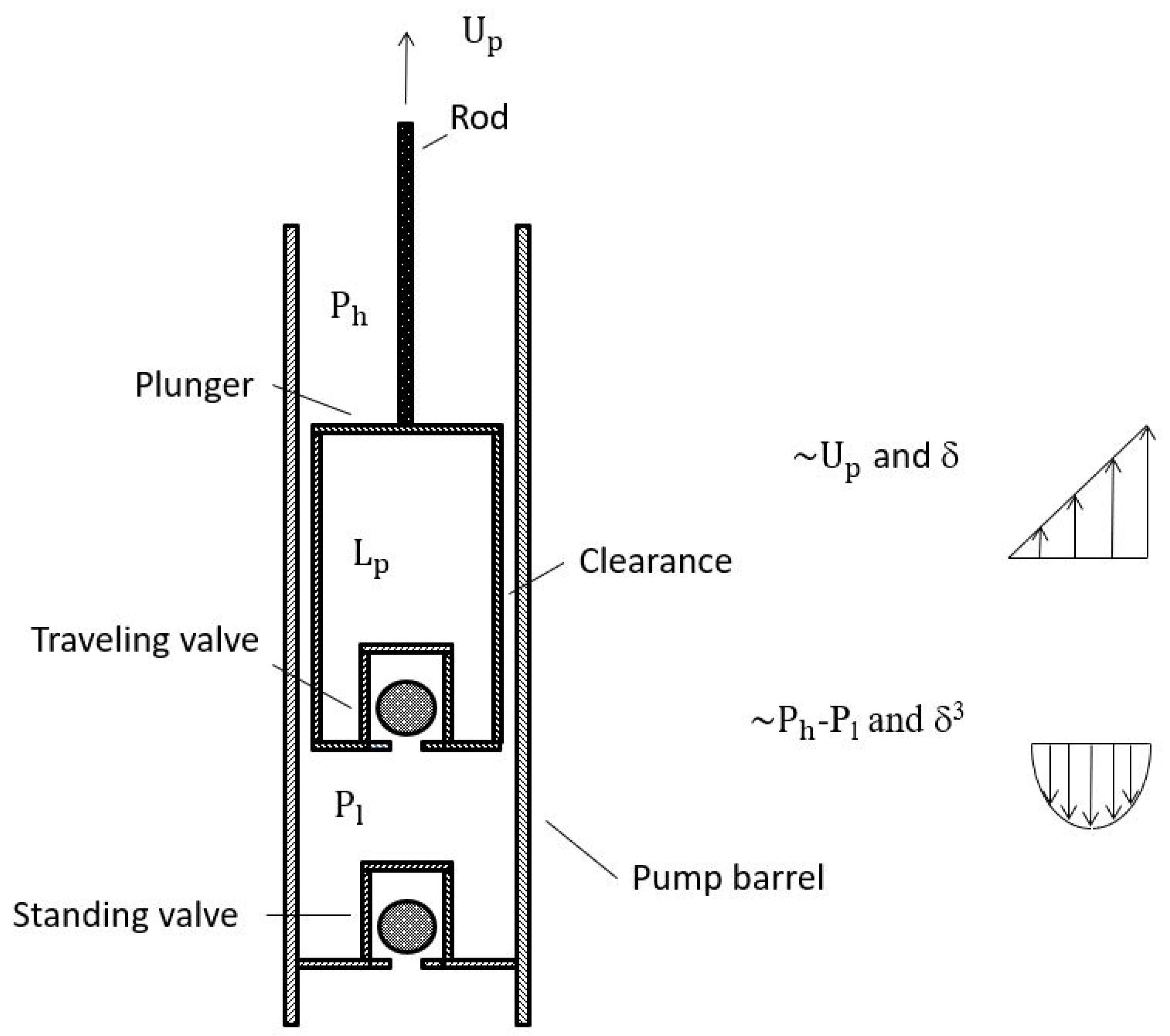
In this paper, for the purpose of illustrating the need for perturbation studies before full-fledged computational fluid dynamics (CFD) simulations, we focus on the so-called leakage issue related to the necessary gap between the plunger and the barrel for the smooth operation of the pump mechanisms [15,16]. As illustrated in Figure 1, a typical sucker rod pump system includes a moving contact area between the traveling unit (plunger) and a fixed tube (barrel). Further more, a traveling ball valve is attached with the end of the plunger and a standing ball valve is installed with the tube near the oil and gas reservoir where the oil and gas are pushed through the fissure formation [17,18] by the so-called formation pressure. To facilitate the reciprocal motions of sucker rod pump systems, a clearance between 3 to 8 mills (one thousandth of an inch) is often reserved to avoid the direct contact (abrasion) between the plunger and the tube [19,20] and to facilitate the transport of sands and particles in oil and gas mixtures [21,22].
Although engineering designs are becoming more and more software driven, physical insights with both temporal and spatial scales are still important in particular during the preliminary design stages. We would like to demonstrate, through the analytical studies of the so-called leakage issues in sucker rod pumps prevalent in petroleum industries, the need for in-depth understanding of contributions of the geometries with extreme spatial ratios and the flow characteristics with specific relaxation time. These insights will help to understand the complexity and many design aspects and enable more efficient use of computational resources with challenging spatial aspect ratios and temporal scales.
In this study, the gap size between the outer surface of the plunger and the inner surface of the barrel is measured with a mill (one thousandth of an inch) whereas the plunger axial length L p is measured with inches or even feet. In the computational approaches, the extreme aspect ratio between the plunger length L p and the plunger outer radius R a ( D a = 2 R a ), or the barrel inner radius R b ( D b = 2 R b ), as well as the gap size δ , defined as R b R a , or a half of the clearance C, does present significant challenges. Furthermore, in engineering practice, the plunger and the barrel are often not concentric and have various levels of eccentricity. The temporal scales, namely relaxation times, are estimated with both expansions in Bessel functions for the annulus flow region and expansions in Fourier series when such a narrow circular flow region is approximated with a rectangular one. These engineering insights derived from the perturbation approaches have been confirmed with the use of full-fledged CFD analyses with sophisticated computational tools. With these initial confirmations published in an early paper [16], new perturbation studies on the sucker rod leakage issue with eccentricities have been presented in this paper. The volume flow rate or rather leakage due to the pressure difference is calculated as a quadratic function with respect to the eccentricity, which matches with the early prediction and publication with comprehensive CFD studies [16]. In short, a healthy combination of ever more powerful modeling tools along with the physics, mathematics, and engineering insights with dimensionless numbers and classical perturbation approaches may provide a balanced and more flexible and efficient strategy in complex engineering designs with the consideration of parametric and phase spaces.

2. Analytical Approaches

As illustrated in Figure 1, during the operation of the sucker rod pump systems, within the gap between the plunger outer surface and the barrel inner surface, two fundamental fluid flows exist, namely, a pressure difference driven Poiseuille flow and a boundary motion induced Couette flow. Both Poiseuille and Couette flows are idealized quasi-static laminar flows and could be governed by the following equations
0 = p z + μ 1 r r r u r ,
where the plunger length is L p , the fluid density is ρ , and the pressure gradient p z is expressed as Δ p L p .
Let’s assume the plunger velocity as U p , namely, u ( R a ) = U p . Furthermore, to be consistent with the leakage definition which is from the top to the bottom, the pressure difference Δ p is positive when the upper region pressure p h is higher than the lower region pressure p l , moreover, the plunger velocity U p is positive when it is moving downwards. Consider a plunger and a barrel pump system with an inner radius R a which is a half of the outer diameter (OD) of the plunger and an outer radius R b which is the half of the inner diameter (ID) of the barrel. The gap denoted as R b R a = δ or the clearance C, which is equivalent to 2 δ is small in comparison with both R a and L p . According to the specific geometries of typical sucker rod pump systems and their operating conditions, we could first ignore the inertial and time dependent effects and denote the pressure difference p h p l as Δ p , the Navier-Stokes equation in the cylindrical coordinate system can be simplified as
Δ p L p = μ r r r u r ,
where p h and p l represent the pressure on the top of the plunger and on the bottom of the plunger, or rather within the sucker rod pump, namely, between the traveling valve and the standing valve, μ refers to the dynamic viscosity of the fluid.
From Equation (2), we derive
u ( r ) = Δ p μ L p r 2 4 + C 1 ln r + C 2 ,
where C 1 and C 2 can be decided based on the boundary conditions.
In order for us to understand the selection of these two constants C 1 and C 2 , let’s continue with this steady linear partial differential Equation (3). For Newtonian viscous fluid, with the linear superposition principle, we can solve the Couette flow and the Poiseuille flow separately. For the Poiseuille flow, on the inner surface of the pump barrel and the outer surface of the plunger, we have the kinematic conditions u ( R a ) = 0 and u ( R b ) = 0 . The velocity profile within the annulus region expressed as Equation (3) has
C 1 = Δ p 4 μ L p R b 2 R a 2 ln R b ln R a , C 2 = Δ p 4 μ L p R a 2 R b 2 R a 2 ln R b ln R a ln R a .
For small clearance, with the Taylor’s expansion, we derive
R b 2 = R a 2 + 2 R a δ + δ 2 , R b 4 = R a 4 + 4 R a 3 δ + 6 R a 2 δ 2 + 4 R a δ 3 + δ 4 , ln R b = ln R a + δ R a δ 2 2 R a 2 + δ 3 3 R a 3 + O ( δ 4 ) ,
hence, the solution of Equation (3) can be expressed as
u ( r ) = Δ p 4 μ L p ( r 2 + 2 R a 2 ln r + R a 2 2 R a 2 ln R a ) .
Moreover, we can easily establish the flow rate through the annulus region as
Q p = R a R b 2 π u ( r ) r d r .
Within O ( δ 3 ) , the flow rate due to the pressure difference, namely Poiseuille flow, Q p is established as
Q p = π Δ p 6 μ L p R a 4 ϵ 3 + 1 2 ϵ 4 11 15 ϵ 5 ,
with the perturbation ratio ϵ = δ R a .
Consequently, the viscous shear force acting on the plunger outer surface in the direction from the top to the bottom can be calculated as
F p = 2 π R a L p μ u r r = R a = π Δ p R a 2 ϵ + 1 6 ϵ 2 1 4 ϵ 3 13 72 ϵ 4 1 144 ϵ 5 .
Likewise, for the Couette flow, with the moving outer surface of the plunger, together with the sucker rod, since the barrel is stationary, thus, for Newtonian viscous fluid, the fluid velocity at the barrel inner surface is zero. Hence, we have the kinematic boundary conditions u ( R a ) = U p and u ( R b ) = 0 , and the flow field can be expressed as
u ( r ) = C 1 ln r + C 2 ,
with
C 1 = U p ln R b ln R a , C 2 = U p ln R b ln R b ln R a .
Using the Taylor’s expansion, we have the simplified expression for the flow field,
u ( r ) = U p R a δ ( ln R b ln r ) .
Notice that the gradient of the velocity profile at the plunger surface matches with the approximation with respect to the thin gap. Moreover, the flow rate due to the shear flow, namely, Couette flow, Q c can still be written as
Q c = R a R b 2 π u ( r ) r d r ,
yet the flow direction is the same as the plunger velocity U p , namely, from the bottom to the top when the upper region pressure p h is higher than the lower region pressure p l .
Again, using the Taylor’s expansions in Equation (5), we have
Q c = π U p R a 2 ϵ + 7 6 ϵ 2 + 11 12 ϵ 3 + 5 72 ϵ 4 13 48 ϵ 5 .
As a consequence, the viscous shear force acting on the plunger surface in the direction from the top to the bottom can be calculated as
F c = 2 π R a L p μ u r r = R a = 2 π L p μ R a U p δ 1 + 1 2 ϵ 1 12 ϵ 2 5 24 ϵ 3 11 144 ϵ 4 + 1 32 ϵ 5 .
It is clear that the leading term of the shear force F c is consistent with the Newtonian fluid assumption with the dynamic viscosity μ . Finally, by combining the Couette and Poiseuille flows, we can have the steady state solution for the velocity profile ϕ ( r ) expressed as
ϕ ( r ) = 1 4 μ Δ p L p r 2 R b 2 R a 2 ln R b ln R a ln r R a 2 ln R b R b 2 ln R a ln R b ln R a + U p ( ln R b ln r ) ln R b ln R a ,
where the Taylor’s expansion in Equation (5) is employed for the coefficients in Equations (4) and (10) with δ = C / 2 .
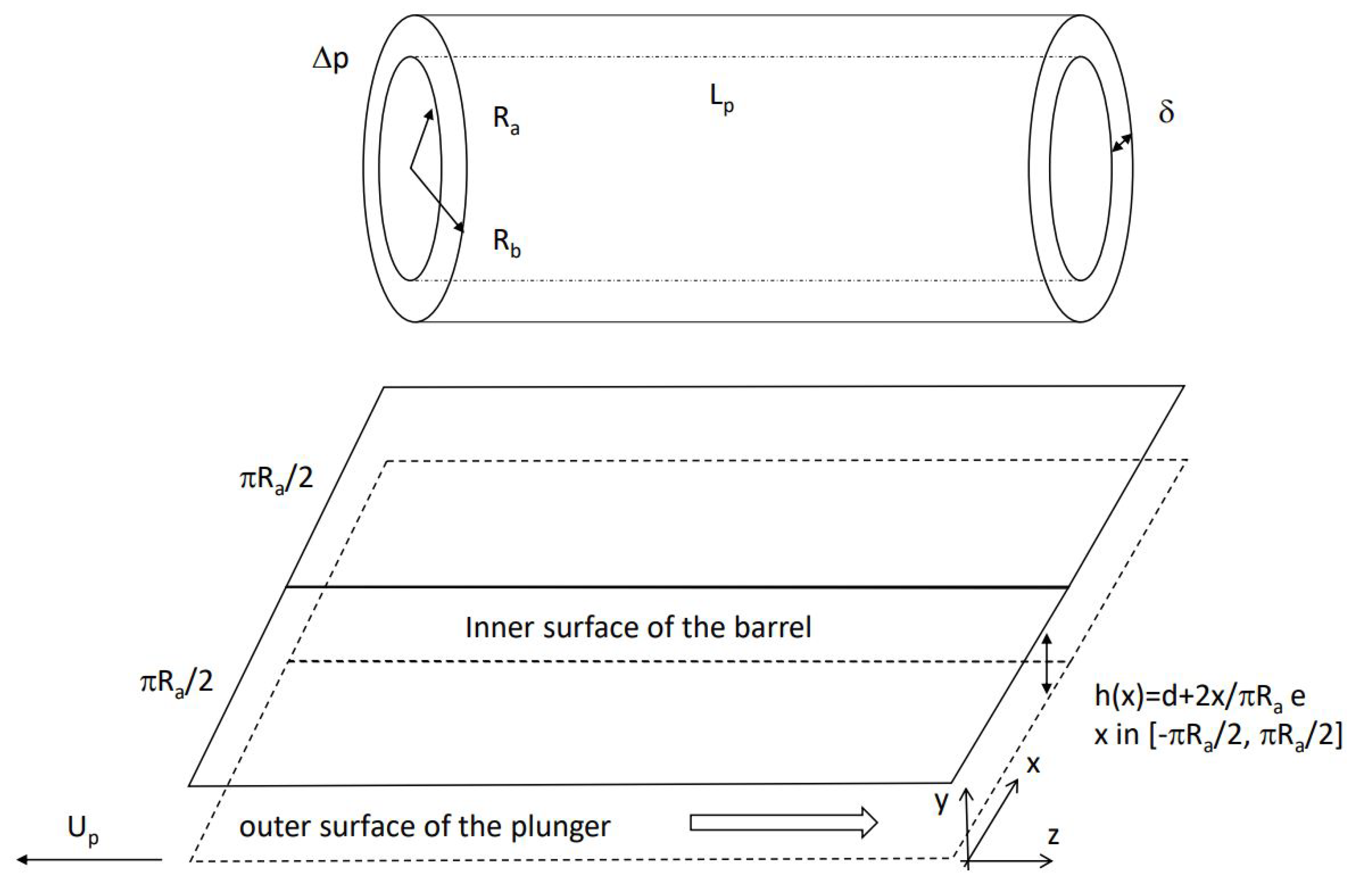
It is the cylindrical coordinate system that renders this seemingly simple problem complicated. If however, we utilize the scaling based on the physics and mathematics, for the large aspect ratio between the plunger length L p and the gap size of the annulus region δ as well as between the plunder radius R a and the gap size, we can cut open the annulus region and simplify the flow domain as a rectangular box as shown in Figure 2 with an axial length L p (z direction), a width 2 π R a (x direction), and a height h (y direction) [23,24]. Notice here that even with the eccentricity which is marked with the difference 2 e between the widest gap and the narrowest gap, or rather e, the distance between the center of the outer surface of the plunger and the center of the inner surface of the barrel, there exists a mid symmetrical axis at x = π R a and the flow regions with x [ 0 , π R a ] and [ π R a , 2 π R a ] are identical. Once we recognize the symmetry, we only need to consider one half of the annulus region with eccentricity and the half of the perimeter is denoted with x [ π R a / 2 , + π R a / 2 ] , as depicted in Figure 2. Of course, for the concentric sucker rod pump, we have a uniform gap with h = δ . However, with eccentricities, such a height will be a function of x which will be discussed separately in Section 3.
For narrow annulus regions, the governing Equation (1) for the Poiseuille and Couette flows can be simplified as
0 = p z + μ 2 w y 2 ,
where w is the velocity component in the axial or z direction and the pressure gradient in z direction is still constant.
Again, for the Poiseuille flow, on the inner surface of the pump barrel at y = h and the outer surface of the plunger at y = 0 , we have the kinematic conditions w ( 0 ) = 0 and w ( h ) = 0 . Hence, the velocity profile within the annulus or rather simplified rectangular region can be expressed as
w ( y ) = Δ p L p y ( h y ) 2 μ .
Furthermore, we can easily establish the flow rate Q p through the concentric annulus region with h = δ as 0 δ 2 π R a w ( y ) d y . The flow rate due to the pressure difference Q p is established as
Q p = 2 π R a Δ p 12 μ L p h 3 = π Δ p 6 μ L p R a 4 ϵ 3 ,
with ϵ = δ R a .
It is not difficult to confirm that the leading term in Equation (7) matches with the simplified expression in (17). Consequently, the viscous shear force acting on the plunger outer surface in the direction from the top to the bottom can be calculated as
F p = 2 π R a L p μ w y y = 0 = π Δ p R a 2 ϵ .
It is again confirmed that the leading term in Equation (8) matches with the simplified expression in (18). Note that the viscous shear force acting on the plunger outer surface in the direction from the top to the bottom. Moreover, due to the small gap size, it is reasonable to assume the shear force acting on the outer surface of the plunger is the same as that of the inner surface of the barrel [23,24]. Thus, these two surface shear forces will balance the total normal force due to the pressure difference over the plunger length, namely,
2 F p = 2 π R a δ Δ p ,
where F p stands for the viscous shear force acting on the plunger outer surface due to Poiseuille flow.
It is clear that Equation (19) is consistent with Equation (18) and the leading term in Equation (8). In fact, in engineering practice, the dominant term is often sufficient. It is obvious that with the help of the physics and mathematics insights [25,26], the simplified rectangular domain is much easier to handle than the annulus region and this advantage will be more crucial when we discuss the relaxation time and the case with eccentricities in Section 3.
Similarly, for the Couette flow, on the inner surface of the pump barrel at y = h and the outer surface of the plunger at y = 0 , we have the kinematic conditions w ( 0 ) = U p and w ( h ) = 0 . Hence, the velocity profile within the annulus or rather simplified rectangular region can be expressed as
w ( y ) = U p ( h y ) h .
Furthermore, we can easily establish the flow rate Q c through the concentric annulus region with h = δ as
Q c = 0 h 2 π R a w ( y ) d y .
The flow rate due to the shear motion at y = 0 (outer surface of the plunger) is established as
Q c = π R a U p h ,
which matches with the leading term in Equation (12).
Consequently, the viscous shear force acting on the plunger outer surface in the direction from the top to the bottom can be calculated as
F c = 2 π R a L p μ w y y = 0 = 2 π L p μ R a U p δ ,
where F c is the viscous shear force acting on the plunger outer surface due to Couette flow.
In comparison with Equation (13), it is again confirmed that the leading term matches with the simplified expression in (22). Furthermore, in order for us to derive Equation (23) from a full-fledged Navier-Stokes equations, we must identify whether or not the fluid flow is in the turbulent region as well as the transient effects [27,28]. First of all, within the gap which is measured in mills, for typical oils, the kinematic viscosity ν at 100 °C is around 5.3 cSt or 5.3 × 10 6   m 2 / s , about five times that of the water and the plunger velocity U p is no more than 40 in/s, thus the so-called Reynolds number R e = U p δ / ν is much smaller than 100 let alone the turbulent flow threshold around 2000. Although the Reynolds number is a clear indication about the quasi-static nature of the Couette and Poiseuille flows within the narrow annulus region, in order to have some guidance with respect to the selection of the sampling time in the experimental measurements of the pressure and the displacement within the sucker rod pump unit, we must investigate further the inertia effects and other time dependent issues. Consider the overall governing equation for the viscous flow within the annulus region R a r R b as expressed as
ρ w t = p z + μ 1 r r r w r ,
where the plunger length is L p and the pressure gradient p z is expressed as Δ p L p .
Note that the pressure difference Δ p is positive when the upper region (top) pressure is higher than the lower region (bottom) pressure which is consistent with the leakage definition. Assuming the plunger velocity is U p , namely, w ( R a ) = U p , by combining the Couette and Poiseuille flows, we can have the steady state solution for the velocity profile ϕ ( r ) expressed in Equation (14).
The final unsteady velocity profile w ( r , t ) can be written as
w ( r , t ) = ϕ ( r ) w ¯ ( r , t ) ,
where the governing equation for the transient part w ¯ ( r , t ) is expressed as
w ¯ t = ν 1 r r r w ¯ r ,
with the boundary conditions w ¯ ( R a , t ) = 0 and w ¯ ( R b , t ) = 0 .
Using the separation of variable method and common special functions [29], we introduce w ¯ ( r , t ) = ψ ( t ) φ ( r ) . As a consequence, we have φ ( R a ) = φ ( R b ) = 0 and the following governing equations
ψ ˙ + ψ τ = 0 ,
1 r d d r r d φ d r + 1 ν τ φ = 0 ,
where ν is the kinematic viscosity and the time scale τ is also called the relaxation time.
For an exponentially decreasing function expressed as e t / τ , the tangent line at the origin always provides an horizontal intercept τ and in general within 5 and 6 times the relaxation time τ , the function is considered as sufficiently close to the steady solutions. From Equations (26) and (27), we have ψ ( t ) = A o e t / τ along with the characteristic expression
φ ( r ) = A 1 J o ( 1 ν τ r ) + A 2 Y o ( 1 ν τ r ) .
It is clear that the characteristic solution expressed in Equation (28) is based on the combination of the first and the second kind of Bessel function satisfying Equation (27) and the characteristic time τ defined as the relaxation time in Equation (26) can be determined by the boundary conditions of φ ( r ) , namely φ ( R a ) = φ ( R b ) = 0 . Therefore, in order for Equations (26) and (27) to have nontrivial solutions, we must have nontrivial or nonzero solutions of A 1 and A 2 , for the following linear system of equations,
A 1 J o ( 1 ν τ R a ) + A 2 Y o ( 1 ν τ R a ) = 0 , A 1 J o ( 1 ν τ R b ) + A 2 Y o ( 1 ν τ R b ) = 0 .
It is clear that we must have the determinant of the coefficient matrix A in Equation (29) equals to zero, namely
d e t ( A ) = J o ( 1 ν τ R a ) Y o ( 1 ν τ R b ) J o ( 1 ν τ R b ) Y o ( 1 ν τ R a ) = 0 .
Finally, combining the steady and the transient solutions, the complete velocity profile can be expressed as
v ( t , r ) = ϕ ( r ) k = 1 A k e t / τ k g k ( r )
where the special function can be expressed as
g k ( r ) = J o ( 1 ν τ k r ) Y o ( 1 ν τ k R a ) J o ( 1 ν τ k R a ) Y o ( 1 ν τ k r )
and the coefficient A k is calculated as
A k = R a R b ϕ ( r ) g k ( r ) r d r R a R b g k ( r ) 2 r d r
In order to separate the effects of the pressure difference and the plunger motion and getting ready for quasi-static or unsteady integrations, Equation (14) is rewritten as follows.
ϕ ( r ) = 1 4 μ Δ p L p ϕ p ( r ) + U p ϕ u ( r ) ,
where we have
ϕ p ( r ) = r 2 R b 2 R a 2 ln R b ln R a ln r R a 2 ln R b R b 2 ln R a ln R b ln R a , ϕ u ( r ) = ln R b ln r ln R b ln R a .
As a consequence, the velocity profile can be expressed as
v ( t , r ) = 1 4 μ Δ p L p ϕ p ( r ) k = 1 E k e t / τ k g k ( r ) + U p ϕ u ( r ) ,
where the coefficient E k is calculated as
E k = R a R b ϕ p ( r ) g k ( r ) r d r R a R b g k ( r ) 2 r d r .
It is known that for viscous fluid to squeeze through a narrow annulus channel, the required pressure gradient or pressure drop given a fixed channel length will be proportional to the gap δ to the power of three, namely, O ( δ 3 ) . The derivation based on Poiseuille flow does confirm such a notion. Moreover, the leakage issue is mostly prominent during the upward stroke, namely, the sucking process. In the upward stroke, the plunger is moving up and as a result will drag fluid up instead of down, which is opposite to the leakage. This effect is due to so-called Couette flow which will introduce a flow rate in a different direction of the power of one, namely, O ( δ ) . Note that in the Couette flow, we focus only on the shear flow introduced by the inner wall (plunger) translational motion whereas no rotational motions as discussed earlier literatures will be considered.
In this paper, through the solution of the partial differential Equation (25) in cylindrical coordinate systems, it is possible for us to derive the relaxation time scales and confirm the quasi-static nature in the majority of oil production systems and the related measuring technologies in particular the sampling frequency around 30 Hz. We will also delineate the transient or rather quasi-static time dependent leakage due to Poiseuille flow from that of Couette flow.
As the plunger is lifting up, the pressure difference Δ p , namely, p h p l or the pressure gradient p z , namely, p h p l L p with L p denotes the plunge axial length will drive the fluid from the high pressure area, namely, the top of the plunger, to the low pressure area, namely, inside the pump chamber and below the plunger. This leakage is due to the so-called Poiseuille flow within the annulus region. It is clear that this leakage is due to the pressure difference. The other flow is due to the viscous shear of the plunger motion. It is important to recognize that during the upstroke, this part of flow rate is in the same direction of the plunger, in this case, from the bottom to the top, which is opposite to the leakage direction. This flow is due to the so-called Couette flow within the annulus region.
Consider a plunger and a barrel pump system with an inner radius R a which is a half of the outer diameter (OD) of the plunger and an outer radius R b which is the half of the inner diameter (ID) of the barrel, in fact, the width of the rectangular domain is simply the perimeter based on the outer radius of the plunger for this first order approximation as illustrated in Figure 2. In practice, the plunger length is measured in inches or even feet whereas the gap size is measured in mills. Thus, the gap denoted as R b R a = δ or the clearance C which is equivalent to 2 δ is very small in comparison with R a and L p . As a consequence, Equation (25) in cylindrical coordinate systems can be expressed in Cartesian coordinate systems as illustrated in Figure 2
w ¯ t = ν 2 w ¯ y 2 ,
with the boundary conditions w ¯ ( 0 , t ) = 0 and w ¯ ( h , t ) = 0 .
Notice that to prepare the discussion in Section 3 with eccentricities, we use the gap function h ( x ) where the coordinate x is selected to represent the entire perimeter of the outer surface of the plunder or the inner surface of the barrel. In the concentric case, we of course have the constant h which is defined as the gap size δ .
Using the separation of variable method and common special functions [29], we introduce w ¯ ( y , t ) = ψ ( t ) φ ( y ) . As a consequence, we have φ ( 0 ) = φ ( h ) = 0 and the following governing equations
ψ ˙ + ψ τ = 0 ,
d 2 φ d y 2 + 1 ν τ φ = 0 ,
From Equation (40) and the corresponding boundary conditions, we can easily obtain the sinusoidal expansion of the function φ ( y ) , namely, sin ( n π y δ ) , with the modal sequence number n. Thus, we have the evaluation of the relaxation time τ expressed as
τ = δ 2 n 2 π 2 ν .
Notice that the Couette effects cannot be approximated by the special function in Equation (32) because of the imposed boundary conditions [30]. Consider a practical case with D = 1.5 in and C = 5 mill, the measured plunger velocity U p can reach around 40 in/sec, namely, R a = 0.75 in and δ = C / 2 = 0.0025 in. For the fluid considered in this paper, we set the density ρ as 1.0014 × 10 3   k g / m 3 and the plunger length L p as 48 in. Assume the dynamics viscosity as 0.9867 cp, we have the Reynolds number based on the clearance ρ C U p / μ as 65.5 which is much smaller than 100. Consequently, we have the following graphical representation in Figure 3 of the determinant expressed in Equation (30). The eigensolutions α k with k = 1 , 2 , , relate to the non-dimensional characteristic time or relaxation time τ k = δ 2 π 2 ν 1 α k 2 . Using the parameters and material properties for the same test case, τ 1 = 4.146 × 10 1 ms, τ 2 = 1.037 × 10 1 ms, and τ 3 = 4.607 × 10 2 ms. In fact, the non-dimensional relaxation times ξ n evaluated by the roots in Figure 3 can be simply expressed as 1 / n 2 . This observation is indeed confirmed by the simplification of the Bessel functions by the sinusoidal functions as R a / δ . It is clear that the typical sampling period of 8.333 ms is sufficiently larger than the five or six times the largest intrinsic relaxation time as predicted in Figure 3. Therefore, the transient or time dependent effects can be ignored. This result is consistent with the finding using full fledged Bessel functions and also confirms the rationale for the non-dimensional quantity δ 2 n 2 π 2 ν chosen for Figure 3.

3. Eccentricity Issues

Finally, we will consider the eccentricity effects on leakage. We hope this comprehensive study will help the industry to better understand the nature of the leakage with respect to pressure difference, eccentricity, and motion related to the plunger of typical sucker rod pump systems [31,32]. In the near future, experimental setups will be established to validate the widely used empirical Patterson Equation and provide more evidences and confirmations to our theoretical studies.
As illustrated in Figure 1, the plunger is in general closely fit within the pump barrel. In general, there will be a clearance of 3 mills for a typical oil well. There are two considerations of this type of simple fitting. First of all, the friction force is due to viscous shear instead of Coulomb friction due to the direct contact or abrasion. This friction force will be demonstrated to be fairly insignificant in comparison with the other forces. Finally, for sandy oil fields, it is also necessary to reserve some space to avoid sticking and abrasion.
The eccentricity of the plunger’s lateral position in the barrel has a great effect on liquid leakage. In practice, for completely eccentric position, leakage rates 60 % greater than for concentric cases can be expected. For a thorough study of eccentricity issues, we introduce the eccentricity as the ratio between the distance e of two centers of the circular outer surface of the plunger and the circular inner surface of the barrel with the gap size δ , i.e., 2 e / C . As illustrated in Figure 2, we can cut the perimeters following the line between the two centers utilizing the symmetry. Therefore, we within half of the perimeter represented with x [ π R a / 2 , + π R a / 2 ] , instead of [ 0 , π R a ] , we can simply interpolate the gap function h ( x ) as
h ( x ) = δ + 2 e x / π R a ,
where the minimum and maximum gap sizes are δ e and δ + e , respectively.
Of course, we always have the eccentricity between 0 and 1, namely, 0 e δ . Due to symmetry, we only need to consider half of the width in this case, namely, x [ π R a / 2 , + π R a / 2 ] , therefore, the velocity component in the axial (z) direction can be expressed as, following Equation (16)
w ( y ) = Δ p L p y [ h ( x ) y ] 2 μ .
Furthermore, we can establish the flow rate Q p through the annulus region with eccentricity e as 2 π R a / 2 + π R a / 2 0 h ( x ) w ( y ) d y d x . The flow rate due to the pressure different Q p is then established as
Q p = Δ p 12 μ L p 2 π R a / 2 + π R a / 2 h ( x ) 3 d x = π R a Δ p 6 μ L p R a 3 ϵ 3 + ϵ 3 ( e δ ) 2 ,
with ϵ = δ R a and the eccentricity is evaluated as e δ .
Due to the complexity of the problem, we also validate our analytical approaches with a full-fledged CFD simulation with various eccentricities.

4. Computational Approaches

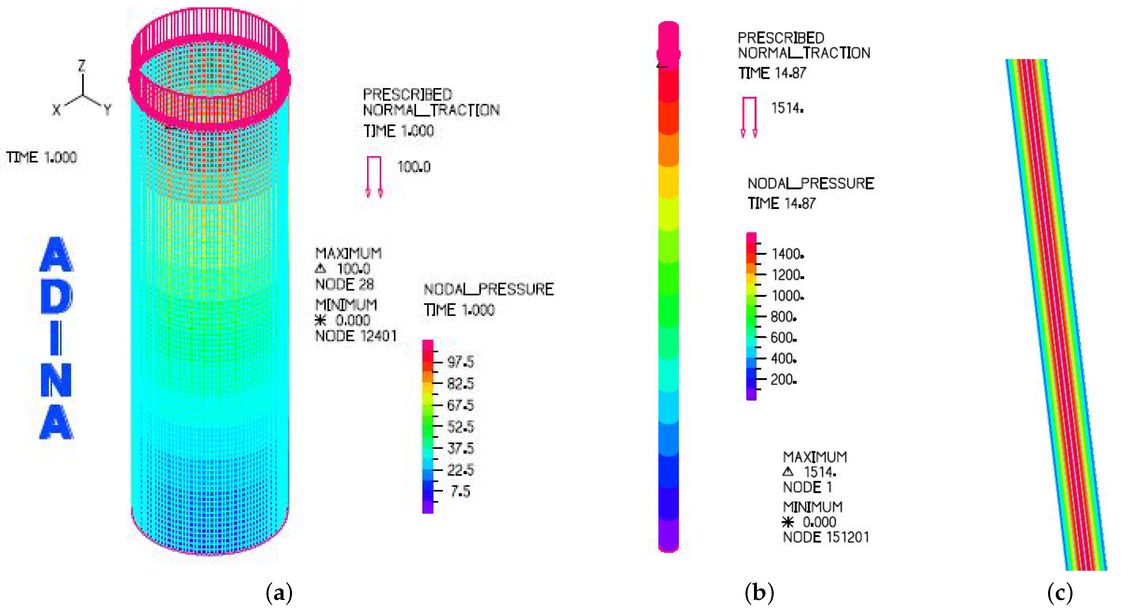
In the computational simulation with ADINA, as illustrated in Figure 4, we applied the pressure differential for three out of four strokes, namely 1295 sample points or 10.792 s, leaving only the stroke during which both the traveling valve (TV) and the standing valve (SV) are closed. Notice that in this test case, we have the stroke per minute (SPM) as 5.067 , thus the period of the sucker rod pumping unit is about 11.842 s. To be consistent with the rate of 120 sampling points per second, namely, the sampling period 8.333 ms, the same time step size is also adopted. Furthermore, to keep the consistent units, in ADINA, the pressure unit is psi, the dynamic viscosity unit is psi·s as well. However, since the spatial dimension is represented with inch, therefore, the conversion factors 32.147 for gravitational constant and 12 for foot and inch conversion must be adopted in the left hand side (LHS) of the Navier-Stokes equation, which means, the density must be adjusted accordingly in addition to the standard conversion from kg/m3 and lbm/ft3. Therefore, the actual input to ADINA if the dimensions are in inche and the pressure differentials are in psi, thus we have 9.358 × 10 5 for effective density and 14.505 × 10 8 for effective dynamic viscosity.
Notice the challenges the extremely small gap size (a few mills, or a few thousandths of an inch) in comparison with the plunger length ( 48 in) have posted to the meshing of the annulus flow region. In fact, in Figure 4, in order to visualize the flow region, we have to zoom in further, as a result only a tiny segment of the annulus region could be depicted. Clearly, for the Poiseuille flow the velocity is zero at the outer surface of the plunger and the inner surface of the barrel as depicted in Figure 4.
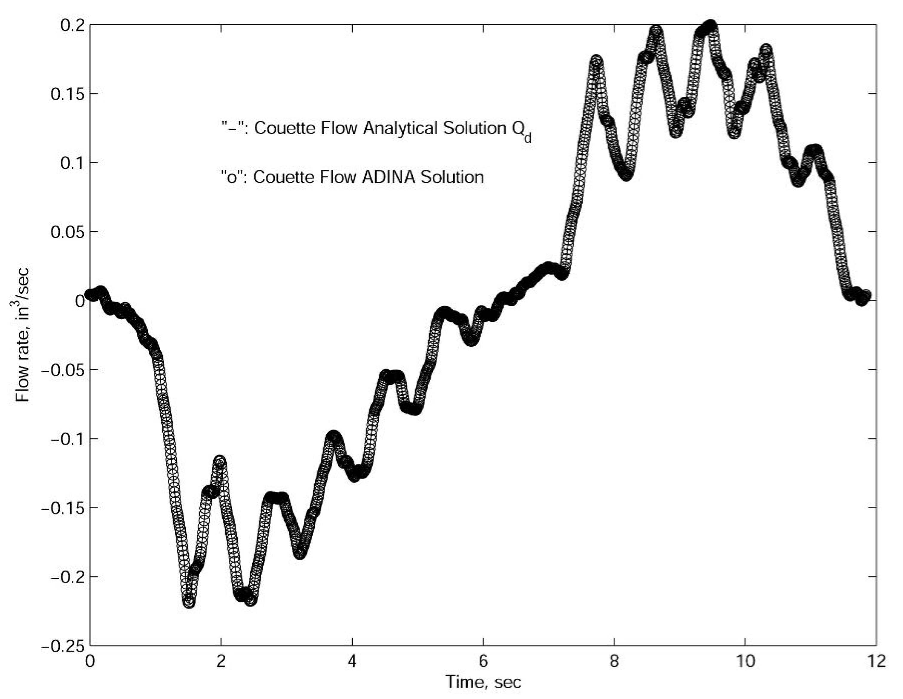
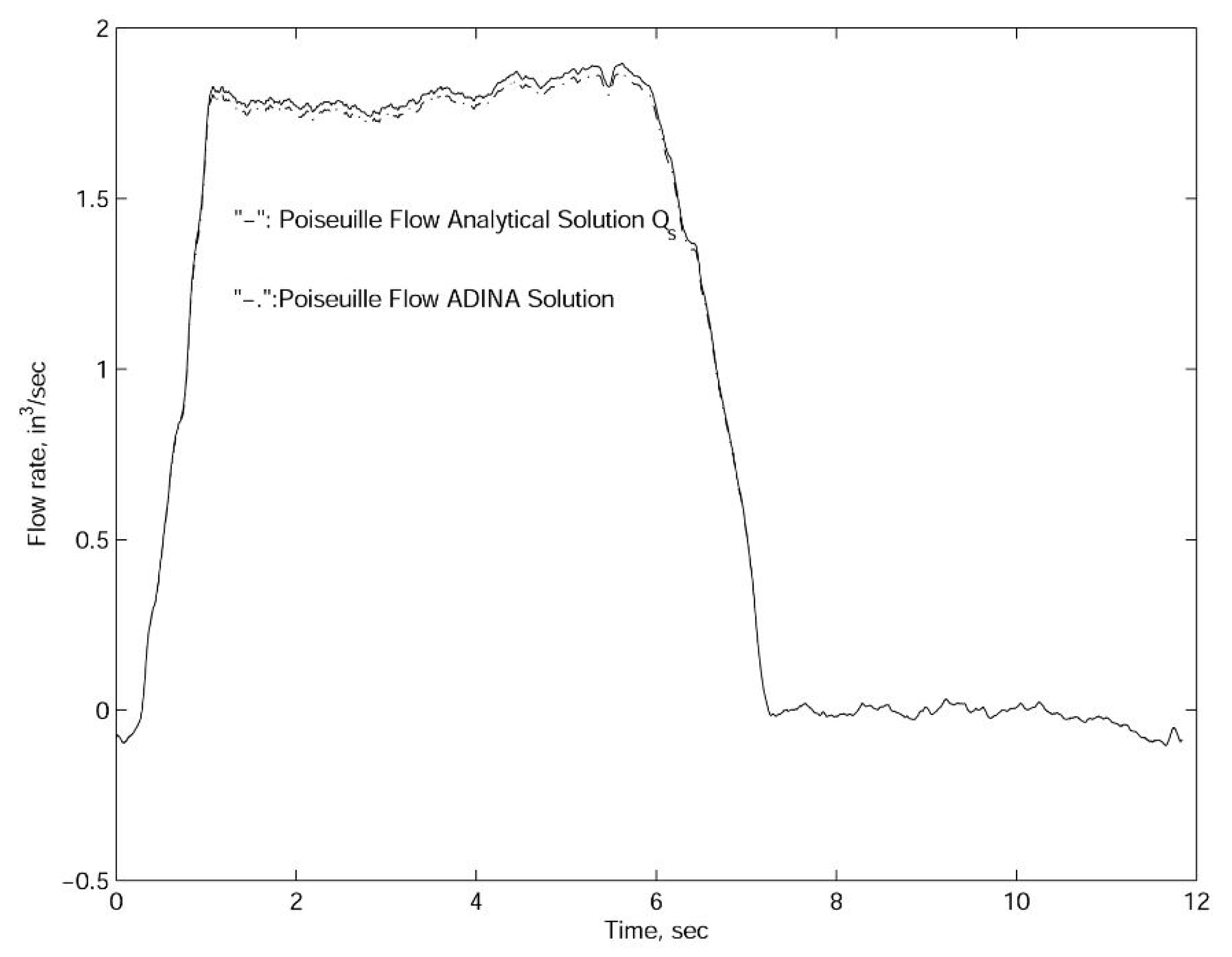
For the concentric case, we utilized the measured plunger velocity and pressure differential data provided by Echometer Company in Wichita Falls, Texas. As depicted in Figure 5 and Figure 6, the simulation results with the actual plunger velocity and pressure differential measurements as well as the inertial effects are nearly identical to those based on the quasi-static analytical results in Equations (7) and (12) which are evaluated without the inertial effects. This fact along with the relaxation time scales confirms that for the typical operation conditions illustrated in this paper and in engineering practice, the inertial effects within the annulus region is insignificant and can be ignored [6,28]. Again, according to the theoretical studies on the relaxation time scales which are confirmed with both the approximated rectangular flow region approximated with Fourier series and the cylindrical flow region calculated with Bessel functions, we can conclude that the time variations of the flow rate as represented in Figure 5 and Figure 6 are in fact quasi-static in nature. The time scales calculated in this paper also reflect the reality that in petroleum industries, the sampling period of 8.333 ms is sufficiently large in order to avoid the transient effects of flows within annulus regions of the sucker rod pump systems. Essentially, we could consider these time variations are snapshots of steady solutions since the relaxation time in the transition solution is very small in comparison with the sampling time.
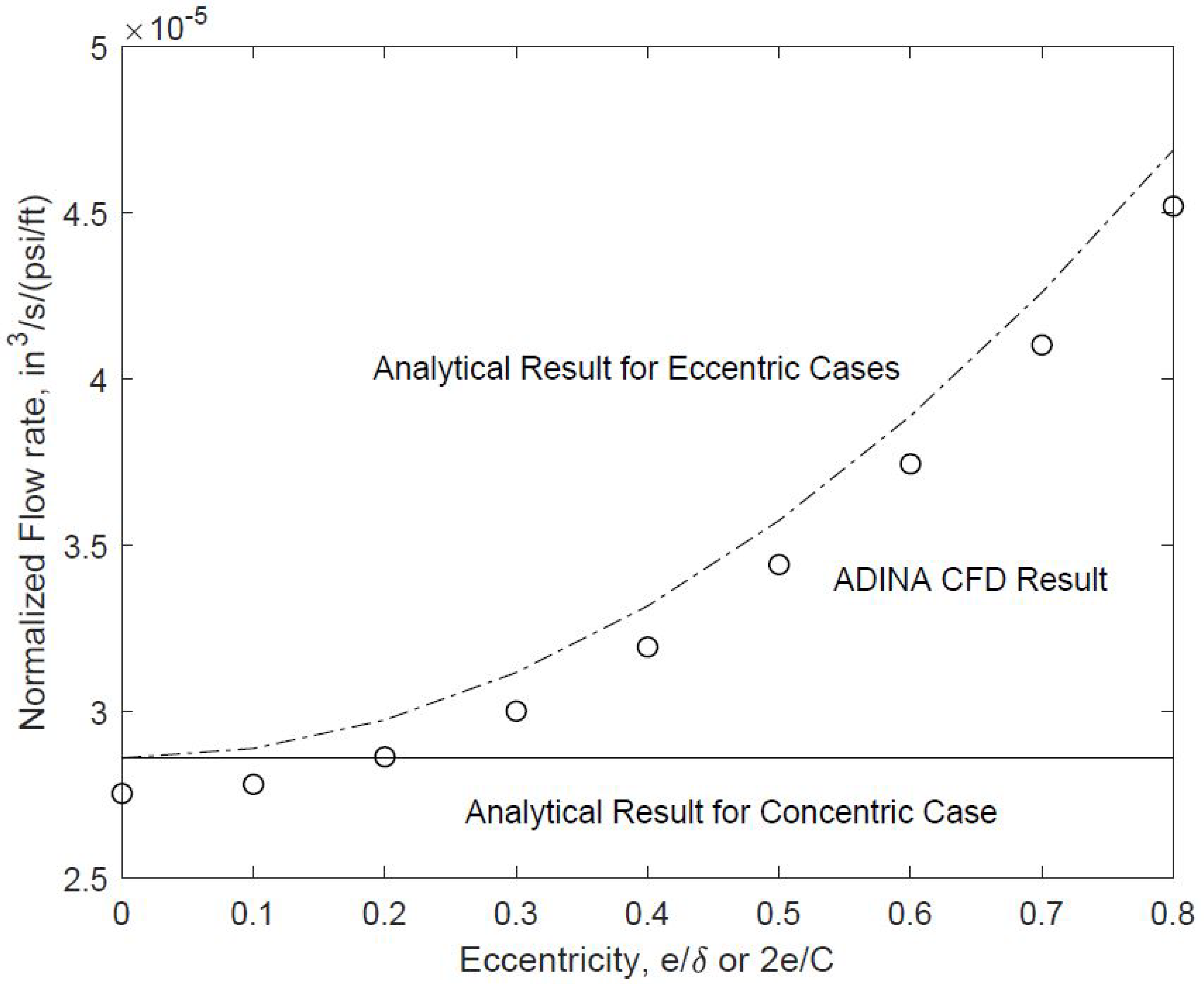
Finally, to incorporate the eccentricity effects, we have resorted to the full-fledged computational fluid dynamics simulation with ADINA [16]. As shown in Figure 5 of the recent ASME Journal of Fluids Engineering paper [16], the computational results with eccentricities were compared with the corresponding concentric case. The new perturbations results depicted in Equation (44) have been compared with the published results in Ref. [16] and documented in Figure 7. In this paper and the early ASME paper [16], the eccentricity is measured by 2 e / C , where e is the shift of the center of the inner cylinder. Different from Ref. [33], instead of studying the leakage rate vs. pump depth and upward moving process, in this paper, we focus on the degree of eccentricity measured by 2 e / C , or e / δ . For the case with D = 1.5 in and C = 5 mill, and the plunger length L p = 4 ft, as illustrated in Figure 7, which has also been confirmed by the recently published computational results in Ref. [16], the misalignment can sometimes introduce up to 90 % elevation of the leakage which is consistent with the analytical prediction based on the perturbation approaches in Equation (44).

5. Conclusions

In petroleum industry, because we must limit the contact as well as the wear and tear of the sucker rod pump plunger and the pump barrel, it is not desirable to completely eliminate the gap between the outer surface of the plunger and the inner surface of the barrel thus the leakage due to the pressure difference which could be as high as a few thousand psi. Furthermore, by reserving a slight gap between the pump plunger and the pump barrel, the sucker rod pump will also be able to operate in oil field with the pollution of sands. It is thus desirable for engineers to have a better understanding along with quantifiable relationship with respect to the leakage and many relevant operational conditions such as the pressure difference and eccentricity. Leakage issue like many engineering problems is multifaceted and complex. For complicated problems such as this, simple analytical, or computational, or empirical studies alone are not sufficient. Yet, we also would like to have more design insights through deep analytical studies before full-fledged simulation tools are employed.
Taking into consideration of the excessively small gap or clearance (a few mills) and its related radius of curvature, pump barrel or plunger radius, we compared and confirmed the matching of the transient solutions with Bessel functions for cylindrical coordinates and Fourier series for Cartesian coordinates. We also compared and confirmed the matching of the relaxation times derived with the first and the second kind Bessel functions for cylindrical coordinates and Fourier series for Cartesian coordinates. The fact that the multiple of the largest relaxation time with five or six is still smaller than the sampling time step which accounts for thirty samples a second for actual cases with physical dimensions and experimental measurements confirms that the quasi-static assumption widely employed in the field is sufficiently accurate and appropriate.
The results derived from the full-fledged three-dimensional computational fluid dynamics (CFD) simulation based on the same transient (or rather quasi-static) pressure difference and plunger velocity which by itself is very challenging due to extreme spatial dimensions does match very well with the analytical solutions based on steady Poiseuille and Couette flows for both concentric and eccentric annulus regions and their rectangular domain approximates. In short, a combination of analytical and computational approaches is presented with comparison to existing empirical measurements. This is in particular evident for the calculation of relaxation times with both cylindrical and Cartesian coordinates which is consistent with the petroleum industry practice in the field. In conclusion, a healthy combination of ever more powerful modeling tools along with the physics, mathematics, and engineering insights with dimensionless numbers and classical perturbation approaches may provide a balanced and more flexible and efficient strategy in complex engineering designs with the consideration of parametric and phase spaces.

Funding

This research received no external funding.

Institutional Review Board Statement

Not applicable.

Informed Consent Statement

Not applicable.

Data Availability Statement

Not applicable.

Acknowledgments

We would like to thank Jim McCoy and engineers at Echometer Company as well as the faculty members and students at Midwestern State University, Texas Tech University System, for providing relevant information on this subject and helpful discussion.

Conflicts of Interest

The authors declare no conflict of interest.

Nomenclature

Cclearance, the diameter difference
D a outer diameter of the plunger
D b inner diameter of the barrel
F p Poiseuille Flow viscous shear force on the plunger outer surface
F c Couette Flow viscous shear force on the plunger outer surface
L p plunger length
p h pressure on the top of the plunger
p l pressure on the bottom of the plunger
p z pressure gradient
Q p Poiseuille Flow flow rate due to the pressure difference
Q c Couette Flow flow rate due to boundary motion
R a outer radius of the plunger
R b inner radius of the barrel
rradius of the annulus flow region, with R a r R b
U p plunger velocity
u ( r ) axial flow velocity profile
Δ p pressure difference
δ gap, the radius difference
μ dynamic viscosity of the fluid
ρ fluid density

References

  1. Karhan, M.K.; Nandi, S.; Jadhav, P.B. Design and optimization of sucker rod pump using prosper. Int. J. Interdiscip. Res. Innov. 2015, 3, 108–122. [Google Scholar]
  2. Romero, O.J.; Almeida, P. Numerical simulation of the sucker-rod pumping system. Ing. Investig. 2014, 34, 4–11. [Google Scholar] [CrossRef] [Green Version]
  3. Takacs, G. Improved designs reduce sucker-rod pumping costs. Oil Gas J. 1996, 94, 5. [Google Scholar]
  4. Dong, Z.; Zhang, M.; Zhang, X.; Pang, X. Study on reasonable choice of electric submersible pump. Acta Pet. Sin. 2008, 29, 128–131. [Google Scholar]
  5. Takacs, G. Sucker Rod Pumping Manual; PennWell Corporation: Tulsa, OK, USA, 2003. [Google Scholar]
  6. Podio, A. Artificial lift. In Encyclopedia of Life Support Systems; UNESCO: Paris, France, 2013; pp. 1–9. [Google Scholar]
  7. Bommer, P.M.; Podio, A.L. The Beam Lift Handbook; Petroleum Extension, The University of Texas at Austin: Austin, TX, USA, 2012. [Google Scholar]
  8. Parameswaran Nampoothiri, M.P. Evaluation of the Effectiveness of Api-Modified Goodman Diagram in Sucker Rod Fatigue Analysis. Master’s Thesis, Texas Tech University, Lubbock, TX, USA, 2001. [Google Scholar]
  9. Wang, S.; Grejtak, T.; Moody, L. Structural designs with considerations of both material and structural failure. ASCE Pract. Period. Struct. Des. Constr. 2017, 22, 04016025. [Google Scholar] [CrossRef]
  10. Wang, S. A revisit of material and structural failures. In Mechanics of Solids, Structures and Fluids; ASME IMECE Paper No. 53079; American Society of Mechanical Engineers: New York, NY, USA, 2015; Volume 9. [Google Scholar]
  11. Karpuz-Pickell, P.; Roderick, R. From failure to success: A metallurgical story on sucker rod pump barrels. In Proceedings of the Sixty Second Annual Meeting of the Southwestern Petroleum Short Course, Lubbock, TX, USA, 22–23 April 2015. [Google Scholar]
  12. Takacs, G. Sucker-Rod Pumping Handbook—Production Engineering Fundamentals and Long-Stroke Rod Pumping; Elsevier: Amsterdam, The Netherlands, 2015. [Google Scholar]
  13. Lea, J.F. What’s new in artificial lift? Part I. World Oil 2012, 5, 79–85. [Google Scholar]
  14. Zhao, R.; Zhang, X.; Liu, M.; Shi, J.; Su, L.; Shan, H.; Sun, C.; Miao, G.; Wang, Y.; Shi, L.; et al. Production optimization and application of combined artificial-lift systems in deep oil wells. In Proceedings of the SPE Middle East Artificial Lift Conference, SPE-184222-MS, Manama, Bahrain, 30 November–1 December 2016; pp. 1–10. [Google Scholar]
  15. Anderson, G.; Liang, B.; Liang, B. The successful application of new technology of oil production in offshore. Foreign Oilfield Eng. 2001, 17, 28–30. [Google Scholar]
  16. Wang, S.; Rowlan, L.; Elsharafi, M.; Ermila, M.A.; Grejtak, T.; Taylor, C.A. On leakage issues of sucker rod pumping systems. ASME J. Fluids Eng. 2019, 141, 111201. [Google Scholar] [CrossRef]
  17. Li, Z.; Song, J.; Huang, Y. Design and analysis for a new energy-saving hydraulic pumping unit. Proc. Inst. Mech. Eng. Part C J. Mech. Eng. Sci. 2018, 232, 2119–2131. [Google Scholar] [CrossRef]
  18. Yu, Y.; Chang, Z.; Qi, Y.; Xue, X.; Zhao, J. Study of a new hydraulic pumping unit based on the offshore platform. Energy Sci. Eng. 2016, 4, 352–360. [Google Scholar] [CrossRef] [Green Version]
  19. Bommer, P.M.; Podio, A.L.; Carroll, G. The measurment of down stroke force in rod pumps. In Proceedings of the Sixty Third Annual Meeting of the Southwestern Petroleum Short Course, Lubbock, TX, USA, 20–21 April 2016. [Google Scholar]
  20. Pons, V. Modified everitt-jennings: A complete methodology for production optimization of sucker rod pumped wells. In Proceedings of the Sixty Second Annual Meeting of the Southwestern Petroleum Short Course, Lubbock, TX, USA, 22–23 April 2015. [Google Scholar]
  21. Copeland, C.D. Fluid extractor. In Proceedings of the Sixty Second Annual Meeting of the Southwestern Petroleum Short Course, Lubbock, TX, USA, 22–23 April 2015. [Google Scholar]
  22. Ermila, M.A. Critical Evaluation of Sucker-Rod String Design Practices in the Hamada Field Libya. Master’s Thesis, University of Miskolc, Miskolc, Hungary, 1999. [Google Scholar]
  23. Back, L.H.; Crawford, D.W. Wall shear stress estimates in coronary artery constrictions. J. Biomed. Eng. 1992, 114, 515–520. [Google Scholar] [CrossRef] [PubMed]
  24. Midvidy, W.; Rouleau, W.T. Stability of Poiseuille flow in elastic tubes. J. Appl. Mech. 1977, 44, 18–24. [Google Scholar] [CrossRef]
  25. Munson, B.R.; Okiishi, T.H.; Huebsch, W.W.; Rothmayer, A.P. Fundamentals of Fluid Mechanics, 7th ed.; John Wiley & Sons: Hoboken, NJ, USA, 2013. [Google Scholar]
  26. Van Dyke, M. Perturbation Methods in Fluid Mechanics; Parabolic Press: Stanford, CA, USA, 1975. [Google Scholar]
  27. Nouri, J.M.; Whitelaw, J.H. Flow of newtonian and non-newtonian fluids in a concentric annulus with rotation of the inner cylinder. ASME J. Fluids Eng. 1994, 116, 821–827. [Google Scholar] [CrossRef]
  28. Rowlan, O.L.; McCoy, J.N.; Lea, J.F. Use of the pump slippage equation to design pump clearances. Private Communication, 2012. [Google Scholar]
  29. Wang, S. Fundamentals of Fluid-Solid Interactions-Analytical and Computational Approaches; Elsevier Science: Amsterdam, The Netherlands, 2008. [Google Scholar]
  30. Hildebrand, F.B. Advanced Calculus for Applications; Prentice Hall: Hoboken, NJ, USA, 1976. [Google Scholar]
  31. Lea, J.F. What’s new in artificial lift? Part II. World Oil 2012, 6, 85–94. [Google Scholar]
  32. Takacs, G. Modern sucker-rod pumping. In PennWell Books; Penn Well Publishing Company: Tulsa, OK, USA, 1993. [Google Scholar]
  33. Wu, Y.; Wu, X.; Wang, Y.; Yuan, Y. A new eccentric annular leakage model for rod pump with couette-poiseuille flow. Int. J. Control. Autom. 2013, 6, 289–302. [Google Scholar]
Figure 1. A typical sucker rod pump system configuration.
Fluids 06 00362 g001
Figure 2. An annulus flow region and its simplified rectangular domain with the width direction in the circumferential direction.
Fluids 06 00362 g002
Figure 3. Eigensolution of the characteristic function and the characteristic time with a = 1 ν R a , b = 1 ν R b , and ξ = τ π ν / δ .
Fluids 06 00362 g003
Figure 4. (a) Pressure and surface mesh. (b) Long plunger. (c) Annulus velocity profile.
Fluids 06 00362 g004
Figure 5. Quasistatic confirmation with CFD results for Couette Flow.
Fluids 06 00362 g005
Figure 6. Quasistatic confirmation with CFD results for Poiseuille Flow.
Fluids 06 00362 g006
Figure 7. Eccentricity effects on the flow rate through the annulus region.
Fluids 06 00362 g007
Publisher’s Note: MDPI stays neutral with regard to jurisdictional claims in published maps and institutional affiliations.