Coherent Streamwise Vortex Structure of a Three-Dimensional Wall Jet


1
Hydropower Research & Development Centre, Druk Green Power Corporation Limited, Thimphu 1351, Bhutan
2
Department of Mechanical Engineering, University of New Brunswick, Fredericton, NB E3B 5A3, Canada
*
Author to whom correspondence should be addressed.
Fluids 2021, 6(1), 35; https://doi.org/10.3390/fluids6010035
Submission received: 21 November 2020
/
Revised: 31 December 2020
/
Accepted: 6 January 2021
/
Published: 11 January 2021
(This article belongs to the Special Issue Turbulent Flow)
Abstract
:The dynamics of the coherent structures in a turbulent three-dimensional wall jet with an exit Reynolds number of 250,000 were investigated using the Snapshot Proper Orthogonal Decomposition (POD). A low-dimensional reconstruction using the first 10 POD modes indicates that the turbulent flow is dominated by streamwise vortex structures that grow in size and relative strength, and that are often accompanied by strong lateral sweeps of fluid across the wall. This causes an increase in the bulging and distortions of streamwise velocity contours as the flow evolves downstream. The instantaneous streamwise vorticity computed from the reconstructed instantaneous velocities has a high level of vorticity associated with these outer streamwise vortex structures, but often has a persistent pair of counter-rotating regions located close to the wall on either side of the jet centerline. A model of the coherent structures in the wall jet is presented. In this model, streamwise vortex structures are produced in the near-field by the breakdown of vortex rings formed at the jet outlet. Separate structures are associated with the near-wall streamwise vorticity. As the flow evolves downstream, the inner near-wall structures tilt outward, while the outer streamwise structures amalgamate to form larger streamwise asymmetric structures. In all cases, these streamwise vortex structures tend to cause large lateral velocity sweeps in the intermediate and far-field regions of the three-dimensional wall jet. Further, these structures meander laterally across the jet, causing a strongly intermittent jet flow.
1. Introduction
Wall jets are a unique and challenging flow to study because the outer layer behaves similarly to a free jet, while closer to the wall, the flow behaves more like a boundary layer. Three-dimensional wall jets are created when a fluid exits from a finite-width opening and develops tangentially along a wall, as shown in Figure 1. One of the most notable features of the three-dimensional wall jet is that the lateral half-width is five to eight times greater than the vertical half-width normal to the wall in the far-field [1,2,3,4,5]. While the cause of such behavior in three-dimensional wall jets is not fully understood, it is known to be caused by the presence of strong mean secondary flows [1]. However, the link between the mean secondary flow (the mean streamwise vorticity) and the unsteady streamwise vorticity associated with coherent structures in the jet is not clear.
Previous researchers like George [6], Glauser [7], Citriniti [8], Citriniti and George [9], Jung et al. [10], and Iqbal and Thomas [11], amongst others, have demonstrated the effectiveness of the Proper Orthogonal Decomposition (POD) technique in extracting coherent structures by applying it to round jets. Using the first few modes, they showed that the POD-filtered reconstructed velocities were able to capture the dynamics and interactions of large-scale structures at different downstream locations. In particular, Citriniti and George [9] were able to observe a pattern in which the coherent ring near the potential core ejects fluid in a volcano-like eruption. Similarly, the coherent structures in three-dimensional wall jets have been the focus of several studies. For example, Matsuda et al. [12] suggested that the mean streamwise vorticity in the wall jet was associated with the passage of horseshoe-like structures formed in the outer shear layer due to the shearing of the mean jet flow with the ambient fluid. Later, using two-point hot-wire measurements in the near-field, Ewing and Pollard [13] found evidence of smaller horseshoe structures close to the wall, near the jet centerline, and proposed that these structures were linked to the larger outer structures proposed by Matsuda et al. [12]. Sun and Ewing [14] expanded the study of Ewing and Pollard [13] and showed that the large outer vortex structures tended to incline while the outer leg of these structures tended to tilt as the flow evolved downstream. This behavior was thought to cause an effective means by which to drive the flow laterally outward along the wall, thus producing the large lateral growth of the wall jet. Similarly, Hall and Ewing [15] used the POD technique on an unsteady wall pressure field measured across a three-dimensional wall jet formed using a long rectangular channel. They noted that the pressure field was rarely symmetric and that there seemed to be two types of structures in the flow—a larger outer structure associated with the outer shear layers and a second, smaller, but energetic structure located near the wall at the center of the jet. Using a spectral linear stochastic estimation (LSE) technique, Hall and Ewing [16] estimated the instantaneous turbulent velocity field from the unsteady wall pressure measurements and determined that there were large horseshoe structures in the flow, consistently with previous investigations, but showed that these structures were primarily asymmetric with respect to the jet centerline. Further, they argued that the passage of these structures was linked to a side-to-side meandering of the wall jet, which, in turn, caused large and strong lateral sweeps of fluid.
Later, Namgyal and Hall [17] used stereoscopic particle image velocimetry (PIV) measurements to examine the vortex structures formed in the near-field of the wall jet at . They performed measurements in the cross-flow plane so as to be able to measure the instantaneous streamwise vorticity in the wall jet. Using a five-POD-mode reconstruction, they found that there were streamwise structures formed in the outer shear layer of the jet that appeared similar to those formed in the near-field of free jets, which are commonly associated with azimuthal modes 5 and 6. The locations of these regions of streamwise vorticity were free to wander around the periphery of the jet at various instants, but did not contribute to the mean streamwise vorticity. There were, however, two pairs of regions of instantaneous counter-rotating streamwise vorticity that were located near the wall, which did not vary its positions appreciably in time; these vortices did contribute to the mean streamwise vorticity and, thus, the mean secondary flow in the jet. From this, Namgyal and Hall [17] proposed that there were two different types of structures in the near-field of the wall jet—long near-wall streamwise structures near the wall that do not wander significantly and streamwise structures in the outer region that are long and do wander. The notion that the near-wall structures contribute the most to the lateral growth of the wall jet is consistent with the findings of Namgyal and Hall [18], who found that the magnitude of the differences of the cross-flow normal Reynolds stresses was the largest near the wall, and argued that it was likely the spatial gradients of these terms that contributed primarily to the turbulent-generated secondary flow in the jet.
Most of the previous studies on wall jets had suggested the evidence of two types of horseshoe structures in the flow—a large outer structure associated with the outer shear layers and a second, smaller, but energetic structure located near the wall at the center of the jet. While the locations of these large outer structures were free to wander around the periphery of the jet, they did not contribute to the mean streamwise vorticity. However, the two pairs of counter-rotating structures that were located near the wall, which did not seems to vary its position, did contribute to the mean streamwise vorticity and, thus, the mean secondary flow in the jet.
While most of the previous studies have focused only on the near-field of the wall jet, not much is known about how these structures behave and contribute to the large lateral growth of the wall jet beyond the near-field. Further, it is also known that the large lateral growth of the jet does not begin until the intermediate field () of the jet. Therefore, the current work builds upon Namgyal and Hall’s [17] study, which focused only on the near-field of a wall jet by extending their measurements downstream from the near-field throughout the intermediate-field of the jet, from = 5 to 30.
2. Experimental Setup
A schematic of a three-dimensional wall jet issuing from a contoured nozzle is shown in Figure 1a, while an arrangement of a laser and cameras is shown in Figure 1b. The Reynolds number at the exit of the jet was set to 250,000. A detailed description of experimental setup can be found in Namgyal and Hall [17].
In order to have statistically converged data, the following numbers of independent pairs of images were taken at various downstream locations: 3000 image pairs up to , 4500 at , and 5100 at . As each vector field could be considered to be statistically independent due to time lag, the uncertainties due to sampling in mean streamwise velocity at a 95% confidence level at the center of the jet at and were determined to be 0.14% to 0.71% and 1.04% to 1.48%, respectively. More details on the uncertainty can be found in Namgyal [19]. Here, x, y, and z are the streamwise, wall-normal, and lateral coordinates, respectively. D is the diameter of the nozzle exit, while is the height of (maximum mean streamwise velocity), and and are the vertical and lateral half-widths corresponding to half of .
3. Experimental Results
POD is a useful technique for extracting energetically dominant modes in a flow by representing a data set as an optimal set of orthogonal basis functions. Using only the first several modes, a low-dimensional, spatially filtered flow-field can be obtained. POD has been widely used for identifying the coherent structures in turbulent flows [7,9,20,21,22,23] and has been previously used by Agelinchaab and Tachie [24] to examine the organization of a three-dimensional wall jet using PIV measurements on the jet centerline. The dense vector fields produced by modern PIV systems are typically handled using the snapshot POD technique proposed by Sirovich [25]. In the present investigation, the snapshot POD was applied to all three components of the stereoscopic PIV data following the method described by Meyer et al. [26], where the autocovariance matrix, , is computed from the fluctuating velocity matrix, , as
which leads to the corresponding eigenvalue problem:
where indicates the eigenvectors corresponding to eigenvalues, . The computed eigenvalues are then arranged according to the size as
where N is the number of snapshots. The eigenvectors of Equation (2) make up a basis for constructing the POD modes, ,
where is the th component of the eigenvector corresponding to from Equation (2), and the discrete–norm is defined as
where vector . With the POD modes arranged as , the POD coefficients, , are computed by projecting the fluctuating part of the velocity, , onto the POD modes as
The fluctuating part of the snapshot can then be reconstructed as
and, by using only the first few modes, a low-dimensional spatially filtered flow-field can be obtained.
In order to ensure that the POD was adequately resolved, 3000 snapshots were used in the present analysis, which is significantly greater than the number of snapshots used in previous studies. For example, Meyer et al. [26] had excellent results using 1000 snapshots in their analysis of a turbulent jet in cross-flow, whereas Agelinchaab and Tachie [24] used 1600 snapshots on the centerline of a three-dimensional wall jet. Since the wall jet development is not axisymmetric due to the presence of the wall, the POD was applied directly on the Cartesian grid produced by the PIV system and not an axisymmetric coordinate system, as is normally performed in free jets [9,22,23]. The energy, , associated with each POD mode
and the distribution of the cumulative energy, , in the first N modes are computed as
The energy contained in each POD mode along with the cumulative energy from to 30 is shown in Figure 2. The associated turbulent kinetic energy in the first 10 modes at the various streamwise locations is also listed in Table 1. The turbulent kinetic energy captured by the first POD mode in the region from contains 3.45% to 6.11% of the total turbulent energy. These results are in line with those of Agelinchaab and Tachie [24], who captured 2.4% of the total turbulent energy in the first POD mode in the developing region and 16.6% in the self-similar region of a three-dimensional wall jet.
As the jet evolves downstream, the energy captured by the first POD mode increases up to ; the cumulative energy in the first 10 modes also increases from 26.49% at to 30.95% at ; both of these suggest that the jet becomes more organized as the jet evolves downstream. This may partially be the result of the rectilinear POD needing more modes to capture the smaller but energetic structures in the near-field shear layer, which are commonly associated with and 6 azimuthal Fourier modes in free jets, as discussed by Namgyal and Hall [17]. As these structures are expected to break down in the intermediate field, fewer modes are thus required to capture the large flow features. As the flow further evolves downstream to , there is a slight decrease in the energy contained in both the first mode and in the first 10 modes. This may signify that a change in wall jet development occurs between and 30.
The shapes of the first and second POD modes at each streamwise measurement location are compared in Figure 3. More details on the first 10 POD mode shapes for various streamwise measurement locations can be found in Namgyal [19]. Here, the contours represent the instantaneous streamwise velocity component of the POD mode, and the vectors represent the instantaneous normal and lateral velocity components. In each case, the vertical and horizontal coordinates have been normalized by their respective half-widths. From up to , the streamwise velocity component associated with the first POD mode shape has two dominant regions with opposite signs located on either side of the jet centerline, which indicates that the modes are antisymmetric. Downstream at , the antisymmetry starts to change, and by , the mode shapes have become symmetric. In all cases, the symmetric modes are associated with the persistence of a large streamwise vortex structure that is oriented to produce strong lateral sweeps across the jet. Note that as these are mode shapes, the time history of the modes causes the signs to reverse, which produces the lateral velocity sweeps in both directions.
The contours of the streamwise velocity associated with the second POD mode at initially have four regions of oppositely signed streamwise velocity (Figure 3b). The corresponding vector field indicates that these are also related to streamwise vortex structures on either side of the jet centerline. In this case, these rotational flow patterns are oriented to induce a strong jet-like inflow of fluid from the upper left side and lower right side of the flow, as well as an outflow of fluid from the lower left side and the top outer right side of the jet. However, by , the contours of the streamwise velocity associated with the second POD mode have only three predominant regions, with a single large positive region at the center of the jet and smaller negative regions on either side of the jet centerline (Figure 3d). These mode shapes have two large vortex pairs located on either side of the jet centerline that are oriented to entrain air at the wall and eject it upward at the centerline, as well as the opposite: to entrain air downward and eject it laterally outward (consistently with the measurement of mean velocity normal to the wall () and mean lateral velocity () reported by Namgyal [19]). This behavior persists until , and by , the mode shapes have changed to be antisymmetric and look like the first POD modes at to 15. These results are consistent with the findings of Hall and Ewing [15,16], who computed the POD on the spanwise fluctuating wall pressure in the near-field of a three-dimensional wall jet and found that the first mode was primarily antisymmetric; they then performed a POD-based spectral LSE and linked this mode to a side-to-side meandering of the jet that was accompanied by strong lateral velocity sweeps. They also found that the second mode was symmetric, but did note that sometimes, the first and second modes would alternate between symmetric and antisymmetric, as occurs here between and 30. This behavior may be linked to a subtle change in jet development and might also be related to the switching of the dominant turbulent production terms, and , at , as reported by Namgyal [19] and Namgyal and Hall [18].
To study the dynamics of the large-scale structures, a low-dimensional reconstruction of the instantaneous velocity field was performed. This has the effect of spatially filtering out the small-scale structures so that the dynamics of the large-scale structures in the wall jet can be examined. Contours of the actual and reconstructed instantaneous velocities using the first 5, 10, and 15 modes at a given instant are compared at in Figure 4. In particular, the reconstructed velocity contours show how effective the POD is at filtering out the small-scale eddies and clearly indicate that the reconstruction of the instantaneous velocity using the first 10 modes provides more information than the reconstructed instantaneous velocity using the first five modes. While reconstructed velocity using 15 modes has more information than using five modes, it does show similar features to those of the reconstruction with 10 modes.
In order to have a reasonable understanding of the flow, a 10-POD-mode reconstruction was selected for use at all measurement positions; note that this is unlike Namgyal and Hall [17], who used only five modes in the near-field of the jet. A low-dimensional reconstruction like this is a compromise; more modes would have allowed for more energy to be captured, but at the expense of having a “noisier” velocity field to examine. The corresponding percentages of the total turbulent energy captured by the first 10 POD modes for various streamwise locations in the jet are given in Table 1. At the very least, this reconstruction captures at least 26.49% of the turbulent kinetic energy. This compares well to reconstructions done in other studies in jets, like Pinier [22], who recovered 30% of the total energy using 12 modes, while Agelinchaab and Tachie [24] recovered 15% and 45% with the first 10 modes in the developing region and self-similar region , respectively.
The low-order reconstructions using the first 10 POD modes at several randomly selected and statistically independent instants for various streamwise locations are shown in Figure 5, Figure 6, Figure 7, Figure 8 and Figure 9. In these figures, the contours in the left column show the instantaneous streamwise velocity, while the vector plots show the normal and lateral instantaneous velocities. In all cases, the mean was added back to the reconstructed velocity fields. The instantaneous streamwise vorticity computed from these reconstructed velocities (with the mean on) are displayed in the right column. In addition, both the mean streamwise velocity and mean streamwise vorticity are also included for comparison at the top of the columns. The distribution of mean velocity normal to the wall and mean lateral velocity can be found in Namgyal [19].
As discussed in more detail by Namgyal and Hall [17] (who only used five modes in their reconstruction), the contours of the mean flow significantly deviate from the contours of the reconstructed instantaneous streamwise velocity at (shown in Figure 5a), where the contours of the reconstructed instantaneous streamwise velocity have a depression on the lower left side and near the wall, as well as a bulging in the contours above on both sides of the jet centerline, which is caused by strong streamwise vortices that draw in ambient fluid on the left side and eject it outward from either side of the jet centerline. However, in all instances, the contours of instantaneous streamwise vorticity loosely correspond to these in-plane rotational flow regions. Since the flow field acquired by the Stereoscopic PIV system is not time resolved, the determination of the exact flow pattern or cycle is very difficult, although a similar pattern can be observed at the other instants where the depressions in the contours of the streamwise velocity are associated with the strong jets of fluid that are created by the presence of highly coherent streamwise vortex pairs. These jets are oriented to cause a strong sweep of fluid across the entire lateral span of the jet (i.e., Figure 5g,k,m) or oriented to eject the fluid outward from the center of the jet (i.e., Figure 5i), and, at times, they produce a rapid inflow of ambient fluid that is typically accompanied by strong lateral ejections of fluid (i.e., Figure 5c,e).
It is interesting to note that in all the reconstructions, the instantaneous streamwise vorticity has a pair of oppositely signed regions that persist near the wall, which are quite similar to the contours of mean streamwise vorticity. Away from the wall, both positive and negative regions of the instantaneous streamwise vorticity persist on both sides of the jet centerline between the snapshots; however, it seems that these regions essentially sum to zero in the mean sense and only the near-wall vorticity remains. This suggests that the streamwise vortex structures in the outer shear layer do not directly contribute to the near-wall vorticity. Furthermore, as these regions appear in a spatially filtered reconstruction, the persistence of these near-wall regions of streamwise vorticity is caused by relatively large-scale structures; this is consistent with the findings of Hall and Ewing [15,16], who argued that there were at least two types of coherent structures in the wall jet—a large one associated with the outer shear layers and smaller but energetic near-wall structures. These regions of near-wall vorticity may be tied to those energetic inner structures [17].
Moving downstream to , the distortion in the contours of the reconstructed streamwise velocity from the mean increases due to the rapid development of the turbulence, likely due to the upstream collapse of the potential core. The inflow of the ambient fluid from the outer regions is driven further into the center of the jet, causing large depressions in instantaneous streamwise velocity contours and a large bulging due to the outward ejection of the fluid, as shown in Figure 6a,g. At other instants, as shown in Figure 6c, a strong lateral sweep of fluid persists, causing the streamwise velocity contours to become strongly distorted to the left. Here too, at , the reconstructed instantaneous velocity field indicates that the rapid sweep and strong ejection of the fluids are accompanied by pairs of strong counter-rotating vortices away from the wall. Again, the near-wall vorticity oriented similarly to the mean seems to persist at each instant, regardless of the location of the vortices away from the wall; however, there is more variation in the magnitude and position of the near-wall streamwise vorticity than at .
By , not only does the distortion of the contours of streamwise velocity from the mean increase, but the highest instantaneous velocities now tend to occur closer to the wall (relative to the vertical half-width) than in the upstream measurements. In addition, the depressions in the contours of the instantaneous streamwise velocity are driven further inward, reaching almost into the center of the jet (i.e., Figure 7c,e,k). At other instants, the inflow is directed downward into the wall at the center, causing the jet to spread laterally across both sides of the jet centerline (i.e., Figure 7i,m). The regions of vorticity away from the wall are large and seem to vary randomly in position; again, these regions do not seem to contribute significantly to the mean vorticity. In general, there appear to be fewer regions of vorticity than at earlier positions, suggesting that the flow is becoming more low-dimensional, perhaps because the streamwise vortex structures are amalgamating. Although the tendency for the wall jet to become more low-dimensional as the flow develops downstream has not previously been noted, this behavior is well documented in free jets where the streamwise vortex structures associated with azimuthal modes 5 and 6 that persist in the near-field eventually merge, and azimuthal mode 1 dominates in the far-field [10,27,28]. The counter-rotating regions of near-wall vorticity on either side of the jet centerline tend to persist at every instant regardless of the position of the vortex structures away from the wall. The regions of counter-rotating vorticity formed outside of the lateral half-widths, in general, tend to resemble the mean streamwise vorticity, but are more irregular than those noted upstream.
Moving further downstream to and 30, there is a significant increase in the distortion of the streamwise velocity contours, which often causes the streamwise velocity contours to intermittently bisect (Figure 9a,e,k) or trisect (Figure 9m). In other instances, the contours of the instantaneous streamwise velocity are pushed down towards the wall due to the inflow of ambient fluid, causing a large spread laterally across the wall (i.e., Figure 8g at and Figure 9g,i at ). In all cases, the instantaneous velocity field confirms the persistence of strong streamwise vortices in the flow, with the size of these vortices increasing as the flow progresses downstream. These vortices are often oriented to cause a large lateral sweep across the jet or, in other instants, a rapid inflow of fluid from the outer regions followed by large ejection of flow to the opposite side of the jet. Rarely do the instantaneous contours seem to resemble the mean flow. Again, a persistence of near-wall vorticity that resembles the mean vorticity is observed. At each instant, there are regions of streamwise vorticity that loosely correspond to the mean vorticity, although at each instant, there is more variation in the location of this vorticity.
Structural Model
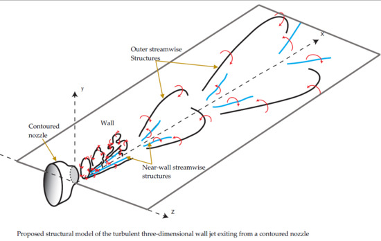
On the basis of the current results, a model of the coherent structures from the near-field to the intermediate field and beyond is shown in Figure 10. The coherent vortex rings formed at the jet exit develop instabilities that lead to the formation of coherent streamwise vortex pairs, similarly to the free jet, whereas the near-wall vorticity could be associated with a set of streamwise vortex pairs that are fixed into position due to the presence of the wall. However, this near-wall vorticity is linked to much longer persistent streamwise vortex structures, consistently with the findings of Hall and Ewing [15], who suggested that there were coherent structures associated with the outer shear layer and smaller but more energetic near-wall structures.
As the flow evolves downstream, the structures in the outer shear layers begin to amalgamate into larger streamwise vortex structures; this behavior is consistent with the free jet literature, as the energetic and 6 azimuthal modes are known to decay downstream of the potential core and give rise to larger antisymmetric turbulence structures, like the azimuthal mode [10,28,29,30]. These structures here have a long lower leg, which causes the persistence of the outer regions of streamwise vorticity in a manner similar to that suggested by Sun [3] and Matsuda et al. [12]. The structures in the intermediate field of the wall jet and beyond are antisymmetric more often than not, as observed by Vouros et al. [31] in the free rectangular jet, and the passage of this structure causes air to be entrained downward and ejected laterally outward to one side, consistently with earlier results [3,15].
Well into the intermediate and beyond, these structures are free to wander laterally across the jet, and this causes the jet flow to be highly intermittent,and sometimes causes the jet to be bisected or trisected. The legs of the trains of these structures intertwine to produce pairs of counter-rotating vorticity, which cause ambient fluid to be entrained and ejected laterally outward. The near-wall vortex structures formed near the jet centerline in the near-field of the wall jet likely persist into the intermediate and far-field. As the flow evolves downstream, the two outer near-wall vortex structures lift from the wall and amalgamate with the coherent streamwise structures produced by the vortex rings. This produces larger streamwise vortices in the jet that cause strong lateral sweeps of fluid. These structures are free to meander laterally from side to side, which, in turn, causes large intermittent deviations of the jet velocity from the mean. However, these near-wall vortex structures remain near the wall, but tilt laterally due to the strong mean lateral flows that produce the wide regions of near-wall vorticity noted at and 30. These structures may be sustained by the production of the near-wall vorticity due to gradients in the normal Reynolds stresses (), as discussed in Namgyal and Hall [18] and Namgyal [19]. The outer regions of near-wall vorticity produced outside of the lateral half-widths in the near-field lift up away from the wall and intertwine with the other streamwise vortex structures, causing large intermittent vortex structures away from the wall as the flow evolves downstream.
4. Concluding Remarks
The dynamics of the coherent structures in a three-dimensional wall jet were investigated using the Snapshot POD technique. The results indicate that a 10-POD-mode reconstruction of the turbulent velocity field is sufficient to extract the dynamics of the coherent structures in the jet. In all cases, the first 10 modes recovered no less than 26.49% of the total turbulent kinetic energy in the flow.
A low-order reconstruction of the instantaneous velocities using the first 10 POD modes indicates that the flow is dominated by streamwise vortex structures that grow in size as the flow evolves downstream. These vortices are oriented to cause strong depressions and bulging in the contours of the streamwise velocity, which are often accompanied by strong lateral sweeps of fluid across the wall. Further downstream, the relative size of the bulging and distortions in the streamwise velocity contours increases, as the fluid from the outer regions is driven deeper into the center of the jet, at times bisecting or trisecting the streamwise velocity contours. This behavior is integral to the large lateral spreading of three-dimensional wall jets and is likely associated with the meandering of the coherent structures in the jet.
The contours of the instantaneous streamwise vorticity computed from the low-dimensio-nal unsteady velocity field indicate strong regions of streamwise vorticity that persist in the outer region of the jet, away from the wall, which are associated with the streamwise vortex structures. In the near-field, the regions of vorticity away from the wall seem to have no direct contribution to the mean streamwise vorticity that persists near the wall. As the jet develops downstream, there are fewer regions of streamwise vorticity, indicating that the flow is becoming more low-dimensional, and regions of instantaneous vorticity that look similar to the mean persist at most instants.
A model for the coherent structures in a wall jet is proposed. Coherent vortex rings produced in the near-field of the wall jet develop instabilities that produce streamwise vortex structures in the outer shear layers. These structures are oriented to drive flow in and out of the potential core of the jet. Relatively long streamwise counter-rotating vortex structures are produced near the wall. As the flow evolves downstream, the two outer near-wall vortex structures lift from the wall and amalgamate with the coherent streamwise structures produced by the vortex rings. This produces larger streamwise vortices in the jet that cause strong lateral sweeps of fluid. These structures are free to meander laterally from side to side, which, in turn, causes large intermittent deviations of the jet velocity from the mean.
Author Contributions
Conceptualization, J.W.H.; Methodology, J.W.H. and L.N.; Software, J.W.H. and L.N.; Supervision. J.W.H.; writing—original draft perparation, L.N.; writing—review and editing, J.W.H. Both authors have read and agreed to the published version of the manuscript.
Funding
This research was funded by Natural Sciences and Engineering Research Council of Canada, and the Druk Green Power Corporation Limited of Bhutan.
Acknowledgments
The authors are grateful for the financial support of th e Natural Sciences and Engineering Research Council of Canada, and the Druk Green Power Corporation Limited of Bhutan.
Conflicts of Interest
The authors declare no conflict of interest.
References
- Launder, B.E.; Rodi, W. The turbulent wall jet-measurements and modelling. Annu. Rev. Fluid Mech. 1983, 15, 429–459. [Google Scholar] [CrossRef]
- Craft, T.J.; Launder, B.E. On the spreading mechanism of the three-dimensional turbulent wall jet. J. Fluid Mech. 2001, 435, 305–326. [Google Scholar] [CrossRef]
- Sun, H. The Effect of Initial Conditions on the Development of the Three-Dimensional Wall Jet. Ph.D. Thesis, McMaster University, Hamilton, ON, Canada, 2002. [Google Scholar]
- Hall, J.W.; Ewing, D. The Development of Three-Dimensional Turbulent Wall Jets Issuing From Moderate Aspect Ratio Rectangular Channels. AIAA J. 2007, 45, 1177–1186. [Google Scholar] [CrossRef]
- Namgyal, L.; Hall, J.W. PIV Measurements of the Turbulent Secondary flow in a Three-Dimensional Wall Jet. In Proceedings of the ASME 2010 3rd Joint US–Engineering Summer Meeting & 8th International Conference on Nanochannels, Microchannels & Minichannels, Montreal, QC, Canada, 1–5 August 2010; ASME: Montreal, QC, Canada, 2010. Paper Number FEDSM–ICNMM2010-30278. [Google Scholar]
- George, W.K. Insight into the dynamics of coherent structures from a proper orthogonal decomposition. In Proceedings of the Symposium on Near Wall Turbulence, Dubrovnik, Yugoslavia, 16–20 May 1988. [Google Scholar]
- Glauser, M.N. Coherent Structures in the Axisymmetric Turbulent Jet Mixing Layer. Ph.D. Thesis, State University of New York at Buffalo, Buffalo, NY, USA, 1987. [Google Scholar]
- Citriniti, J.H. Experimental Investigation into the Dynamics of the Axisymmetric Mixing Layer Utilizing the Proper Orthogonal Decomposition. Ph.D. Thesis, State University of New York, New York, NY, USA, 1996. [Google Scholar]
- Citriniti, J.H.; George, W.K. Reconstruction of the global velocity field in the axisymmetric mixing layer utilizing the proper orthogonal decomposition. J. Fluid Mech. 2000, 418, 137–166. [Google Scholar] [CrossRef]
- Jung, D.; Gamard, S.; George, W. Downstream evolution of the most energetic modes in a turbulent axisymmetric jet at high Reynolds number. Part 1. The near-field region. J. Fluids Mech. 2004, 514, 173–204. [Google Scholar] [CrossRef] [Green Version]
- Iqbal, M.O.; Thomas, F.O. Coherent structures in a turbulent jet via a vector implementation of the proper orthogonal decomposition. J. Fluid Mech. 2007, 571, 281–326. [Google Scholar] [CrossRef]
- Matsuda, H.; Iida, S.; Hayakawa, M. Coherent structures in three-dimensional wall jet. J. Fluids Eng.-Trans. ASME 1990, 112, 462–467. [Google Scholar] [CrossRef]
- Ewing, D.; Pollard, A. Evolution of the large-scale motions in a three-dimensional wall jet. In Proceedings of the 28th AIAA Fluid Dynamics Conference/4th AIAA Shear Flow Control Conference, Snowmass Village, CO, USA, 29 June–2 July 1997. Paper No. 97-1964. [Google Scholar]
- Sun, H.; Ewing, D. Development of the large-scale structures in the intermediate region of the three-dimensional wall jet. In Proceedings of the Fluids Engineering Division Summer Meeting, Montreal, QC, Canada, 14–18 July 2002; ASME: New York, NY, USA, 2002. Paper Number FEDSM2002-31414. [Google Scholar]
- Hall, J.W.; Ewing, D. The Asymmetry Of The Large-Scale Structures In Turbulent Three-Dimensional Wall Jets Exiting Long Rectangular Channels. J. Fluids Eng.-Trans. ASME 2007, 129, 929–941. [Google Scholar] [CrossRef]
- Hall, J.W.; Ewing, D. Spectral Linear Stochastic Estimation of the Turbulent Velocity in a Square Three-Dimensional Wall Jet. J. Fluids Eng.-Trans. ASME 2010, 132, 051203. [Google Scholar] [CrossRef]
- Namgyal, L.; Hall, J. Coherent Streamwise Vortex Structures in the Near-Field of the Three-Dimensional Wall Jet. J. Fluids Eng.-Trans. ASME 2013, 135. [Google Scholar] [CrossRef]
- Namgyal, L.; Hall, J. Reynolds stress distribution and turbulence generated secondary flow in the turbulent three-dimensional wall jet. J. Fluid Mech. 2016, 800, 613–644. [Google Scholar] [CrossRef]
- Namgyal, L. Three-Component Particle Image Velocimetry Measurements in a Turbulent Three-Dimensional Wall Jet. Ph.D. Thesis, University of New Brunswick, Fredericton, NB, Canada, 2012. [Google Scholar]
- Sullivan, P.; Pollard, A. Coherent structure identification from the analysis of hot-wire data. Mater. Sci. Technol. 1996, 7, 1498. [Google Scholar] [CrossRef]
- Ukeiley, L.S.; Cordier, L.; Delville, J.; Glauser, M.; Bonnet, J.P. Examination of large-scale structures in turbulent plane mixing layer. Part I. J. Fluid Mech. 1999, 391, 123. [Google Scholar]
- Pinier, J. Low-dimensional Techniques for Active Control of High-speed Jet Aeroacoustics. Ph.D. Thesis, Syracuse University, Syracuse, NY, USA, 2007. [Google Scholar]
- Tinney, C.E.; Glauser, M.N.; Ukeiley, L.S. Low-dimensional characteristics of a transonic jet. Part 1: Proper orthogonal decomposition. J. Fluid Mech. 2008, 612, 107–141. [Google Scholar] [CrossRef]
- Agelinchaab, M.; Tachie, M.F. Characteristics of Turbulent Three-Dimensional Wall Jets. J. Fluids Eng.-Trans ASME 2011, 133, 021201. [Google Scholar] [CrossRef]
- Sirovich, L. Turbulence and the dynamics of coherent structures. Part I: Coherent Structures. Q. Appl. Math. 1987, 45, 561–571. [Google Scholar] [CrossRef] [Green Version]
- Meyer, K.E.; Pedersen, J.M.; Ozcan, O. Turbulent jet in crossflow analysed with Proper Orthogonal Decomposition. J. Fluids Mech. 2007, 583, 199–227. [Google Scholar] [CrossRef] [Green Version]
- Fuchs, H.; Mercker, E.; Michel, U. Large-scale coherent structures in the wake of axisymmetric bodies. J. Fluid Mech. 1979, 93, 185–207. [Google Scholar] [CrossRef]
- Hall, J.; Pinier, J.; Hall, A.; Glauser, M. Two-point correlations of the near and far-field pressure in a transonic jet. In Proceedings of the ASME Joint U.S European Fluids Engineering Summer Meeting, Miami, FL, USA, 17–20 July 2006. Paper Number FEDSM2006-98458. [Google Scholar]
- Gamard, S.; Jung, D.; George, W.K. Downstream evolution of the most energetic modes in a turbulent axisymmetric jet at high Reynolds number—Part 2. The far-field region. J. Fluid Mech. 2004, 514, 205–230. [Google Scholar] [CrossRef]
- Hussain, A.K.M.F.; Clark, A.R. On the coherent structure of the axisymmetric mixing layer: A flow-visualization study. J. Fluid Mech. 1981, 104, 263–294. [Google Scholar] [CrossRef]
- Vouros, A.P.; Panidis, T.; Pollard, A.; Schwab, R.R. Near field vorticity distributions from a sharp-edged rectangular jet. Int. J. Heat Fluid Flow 2015, 51, 383–394. [Google Scholar] [CrossRef]
Figure 1.
(a) Experimental setup of a three-dimensional wall jet issuing from a contoured nozzle and (b) the laser and particle image velocimetry (PIV) camera arrangement in the experimental setup.
Figure 1.
(a) Experimental setup of a three-dimensional wall jet issuing from a contoured nozzle and (b) the laser and particle image velocimetry (PIV) camera arrangement in the experimental setup.

Figure 2.
Relative and cumulative turbulent energy distribution in the Proper Orthogonal Decomposition (POD) eigenmodes at (a) , (b) , (c) , (d) , and (e) .
Figure 2.
Relative and cumulative turbulent energy distribution in the Proper Orthogonal Decomposition (POD) eigenmodes at (a) , (b) , (c) , (d) , and (e) .

Figure 3.
Comparison of the first and second POD eigenmodes: (a) and (b) , (c) and (d) , (e) and (f) , (g) and (h) , and (i) and (j) .
Figure 3.
Comparison of the first and second POD eigenmodes: (a) and (b) , (c) and (d) , (e) and (f) , (g) and (h) , and (i) and (j) .

Figure 4.
Comparison of POD reconstructions of the instantaneous velocities at : (a) and (b) Actual, (c) and (d) using the first five POD modes, (e) and (f) using the first 10 POD modes, and (g) and (h) using the first 15 POD modes.
Figure 4.
Comparison of POD reconstructions of the instantaneous velocities at : (a) and (b) Actual, (c) and (d) using the first five POD modes, (e) and (f) using the first 10 POD modes, and (g) and (h) using the first 15 POD modes.

Figure 5.
POD reconstruction of the instantaneous velocity using the first 10 modes and the reconstructed instantaneous streamwise vorticity at . The mean streamwise velocity (normalized) and mean streamwise vorticity are shown in the first row.
Figure 5.
POD reconstruction of the instantaneous velocity using the first 10 modes and the reconstructed instantaneous streamwise vorticity at . The mean streamwise velocity (normalized) and mean streamwise vorticity are shown in the first row.


Figure 6.
POD reconstruction of the instantaneous velocity using the first 10 modes and the reconstructed instantaneous streamwise vorticity at . The mean streamwise velocity (normalized) and mean streamwise vorticity are shown in the first row.
Figure 6.
POD reconstruction of the instantaneous velocity using the first 10 modes and the reconstructed instantaneous streamwise vorticity at . The mean streamwise velocity (normalized) and mean streamwise vorticity are shown in the first row.


Figure 7.
POD reconstruction of the instantaneous velocity using the first 10 modes and the reconstructed instantaneous streamwise vorticity at . The mean streamwise velocity (normalized) and mean streamwise vorticity are shown in the first row.
Figure 7.
POD reconstruction of the instantaneous velocity using the first 10 modes and the reconstructed instantaneous streamwise vorticity at . The mean streamwise velocity (normalized) and mean streamwise vorticity are shown in the first row.


Figure 8.
POD reconstruction of the instantaneous velocity using the first 10 modes and the reconstructed instantaneous streamwise vorticity at . The mean streamwise velocity (normalized) and mean streamwise vorticity are shown in the first row.
Figure 8.
POD reconstruction of the instantaneous velocity using the first 10 modes and the reconstructed instantaneous streamwise vorticity at . The mean streamwise velocity (normalized) and mean streamwise vorticity are shown in the first row.


Figure 9.
POD reconstruction of the instantaneous velocity using the first 10 modes and the reconstructed instantaneous streamwise vorticity at . The mean streamwise velocity (normalized) and mean streamwise vorticity are shown in the first row.
Figure 9.
POD reconstruction of the instantaneous velocity using the first 10 modes and the reconstructed instantaneous streamwise vorticity at . The mean streamwise velocity (normalized) and mean streamwise vorticity are shown in the first row.


Figure 10.
Proposed structural model of the turbulent three-dimensional wall jet exiting from a contoured nozzle.
Figure 10.
Proposed structural model of the turbulent three-dimensional wall jet exiting from a contoured nozzle.


Table 1.
Relative and cumulative turbulent energy content in the POD eigenmodes (%).
| 1st | 2nd | 3rd | 4th | 5th | 6th | 7th | 8th | 9th | 10th | Total | |
|---|---|---|---|---|---|---|---|---|---|---|---|
| 5 | 3.45 | 3.17 | 3.15 | 3.02 | 2.89 | 2.75 | 2.49 | 2.18 | 1.76 | 1.63 | 26.49 |
| 10 | 5.25 | 4.44 | 4.05 | 3.51 | 2.51 | 2.17 | 2.03 | 1.92 | 1.60 | 1.58 | 29.06 |
| 15 | 6.31 | 5.99 | 3.83 | 3.35 | 2.18 | 2.07 | 2.06 | 1.87 | 1.67 | 1.62 | 30.95 |
| 20 | 6.50 | 6.19 | 3.36 | 3.14 | 2.39 | 2.22 | 2.15 | 1.72 | 1.54 | 1.49 | 30.70 |
| 30 | 6.11 | 5.61 | 2.90 | 2.77 | 2.55 | 2.39 | 2.28 | 1.62 | 1.56 | 1.53 | 29.32 |
Publisher’s Note: MDPI stays neutral with regard to jurisdictional claims in published maps and institutional affiliations. |
© 2021 by the authors. Licensee MDPI, Basel, Switzerland. This article is an open access article distributed under the terms and conditions of the Creative Commons Attribution (CC BY) license (http://creativecommons.org/licenses/by/4.0/).
Share and Cite
MDPI and ACS Style
Namgyal, L.; Hall, J.W. Coherent Streamwise Vortex Structure of a Three-Dimensional Wall Jet. Fluids 2021, 6, 35. https://doi.org/10.3390/fluids6010035
AMA Style
Namgyal L, Hall JW. Coherent Streamwise Vortex Structure of a Three-Dimensional Wall Jet. Fluids. 2021; 6(1):35. https://doi.org/10.3390/fluids6010035
Chicago/Turabian StyleNamgyal, Lhendup, and Joseph W. Hall. 2021. "Coherent Streamwise Vortex Structure of a Three-Dimensional Wall Jet" Fluids 6, no. 1: 35. https://doi.org/10.3390/fluids6010035