
Alumina Ceramic Nanofibers: An Overview of the Spinning Gel Preparation, Manufacturing Process, and Application
by
 ,
,
Meng Xia
1,
Shuyu Ji
1,
Yijun Fu
1,
Jiamu Dai
1,
Junxiong Zhang
1,*,
Xiaomin Ma
2 and
Rong Liu
1,* 1
School of Textile & Clothing, National & Local Joint Engineering Research Center of Technical Fiber Composites for Safety and Health, Nantong University, Nantong 226019, China
2
National Equipment New Material & Technology (Jiangsu) Co., Ltd., Suzhou 215100, China
*
Authors to whom correspondence should be addressed.
Gels 2023, 9(8), 599; https://doi.org/10.3390/gels9080599
Submission received: 22 June 2023
/
Revised: 13 July 2023
/
Accepted: 19 July 2023
/
Published: 25 July 2023
(This article belongs to the Special Issue Gels as High-Performance Thermal Insulation Materials)
Abstract
:As an important inorganic material, alumina ceramic nanofibers have attracted more and more attention because of their excellent thermal stability, high melting point, low thermal conductivity, and good chemical stability. In this paper, the preparation conditions for alumina spinning gel, such as the experimental raw materials, spin finish aid, aging time, and so on, are briefly introduced. Then, various methods for preparing the alumina ceramic nanofibers are described, such as electrospinning, solution blow spinning, centrifugal spinning, and some other preparation processes. In addition, the application of alumina ceramic nanofibers in thermal insulation, high-temperature filtration, catalysis, energy storage, water restoration, sound absorption, bioengineering, and other fields are described. The wide application prospect of alumina ceramic nanofibers highlights its potential as an advanced functional material with various applications. This paper aims to provide readers with valuable insights into the design of alumina ceramic nanofibers and to explore their potential applications, contributing to the advancement of various technologies in the fields of energy, environment, and materials science.
1. Introduction
According to the current research status, alumina ceramic nanofibers have attracted widespread attention. Alumina ceramic nanofibers have many excellent properties, such as good flexibility, high specific surface area, and the strong adsorption of nanomaterials; alumina nanofibers also show many excellent properties of high-temperature oxidation resistance, excellent mechanical properties, and outstanding chemical stability. These excellent characteristics make it widely used in the fields of high-temperature heat insulation, separations, sound absorption, catalysis, etc.
Alumina ceramic nanofibers generally refer to fibers with an alumina content of more than 70% [1]; the remaining components usually consist of silica, boron nitride, iron oxide, zirconia, etc. Alumina ceramic nanofibers are polycrystalline inorganic fibers, whose main crystal shape can be α-, γ-, δ-, and θ-alumina [2,3]; among them, α-Al2O3 is the most thermodynamically stable of the alumina crystal forms, and γ-Al2O3 is almost completely converted to α-Al2O3 at high temperatures above 1300 °C [4]. Alumina ceramic nanofibers with different properties can be prepared by several different methods. For example, the Cu-Al2O3 nanofiber membrane prepared by electrospinning has the advantages of high mechanical strength, good flexibility, high catalytic activity, and high porosity, which can be used for the removal of organic pollutants; another example is the Al2O3-stabilized nanofibers prepared by solution blow spinning. ZrO2 fiber air filter paper has excellent flexibility and foldability. With the appropriate production process or post-treatment method, alumina fiber can also be processed into fiber film, fiber cotton, fiber felt, fiberboard, fiber paper, etc. The fibers can also be processed into different forms, such as two-dimensional long or short ceramic fibers, thin films, three-dimensional ceramic fiber aerogels, etc. These different forms of fibers have different uses; for example, two-dimensional long or short ceramic fibers are often used as structural reinforcements for composite materials and lining materials for high-temperature insulation. Three-dimensional ceramic fiber aerogels are commonly used in the field of sound absorption to reduce the noise pollution caused by traffic and engineering construction. Furthermore, because of their high strength and some special electrical and optical properties, alumina ceramic nanofibers can also be used as functional materials in some special fields [5,6]; for example, alumina ceramic nanofibers can be used as catalyst carriers to prepare catalyst materials, to achieve the catalytic degradation of pollutants in the environment. Alumina fiber can also be used to blend with other polymers to obtain battery separators through a certain process, making batteries safer under high temperature conditions.
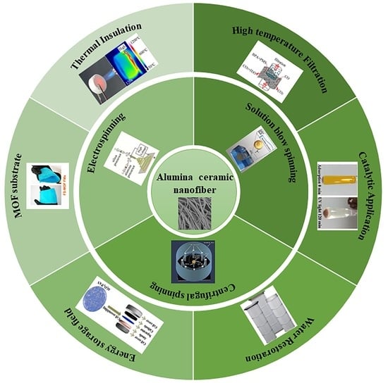
In this paper, the preparation of alumina spinning gel, spinning processes, and their application are reviewed (Figure 1). The material system for preparing alumina spinning gel is firstly introduced, and then the methods for preparing alumina ceramic nanofibers, including centrifugal spinning, electrostatic spinning and solution blowing, are described. Then, the applications of alumina nanofibers in thermal insulation, high temperature filtration, catalysis, water remediation, and energy storage are mainly introduced. Finally, the future development and prospects of alumina ceramic nanofibers are presented, which provides a certain reference value for further research on alumina ceramic nanofibers.
2. Preparation of Alumina Spinning Gel
The preparation of alumina spinning gel plays a crucial role in the fabrication of alumina ceramic nanofibers. The selection of the raw materials, their ratios, aging time, and concentrations in the precursor solution can significantly impact the morphology, structure, and properties of the resulting nanofibers during the subsequent spinning process.
In the preparation process of alumina nanofibers, alumina spinning gel is one of the key links. In the preparation of alumina spinning gel, aluminum chloride hexahydrate, aluminum isopropyl oxide, aluminum sulfate, aluminum powder, and aluminum nitrate are generally used as the experimental aluminum sources. During experiments, the alumina spinning gel is prepared by using polyvinyl pyrrolidone (PVP), polyvinyl alcohol (PVA), polyethylene oxide (PEO), polyacrylic acid (PAA), and other polymers as support materials or fiber-forming materials. Then, according to the experimental requirements, researchers add other experimental aids such as acetic acid, hydrochloric acid, ethylene glycol, etc., to prepare an alumina spinning gel that meets the experimental requirements, and then, they move through the preparation process of nanofibers, such as electrospinning, solution jet spinning, centrifugal spinning, etc., to prepare the alumina nanofibers. The ratio of the alumina spinning gel is also adjusted according to the requirements of the synthesis, and according to the shape and structure of the required product, the experimental conditions are also different in the subsequent drying and calcination. Table 1 lists the formation and experimental conditions of the precursor sol for the preparation of the alumina nanofibers.
3. Methods for the Preparation of Alumina Nanofibers
Compared with other oxide nanofibers such as silicon dioxide (SiO2), zirconia (ZrO2), titania (TiO2), etc., the research on alumina nanofibers is still in the early stage. The preparation of alumina nanofibers is mainly via electrospinning, solution blowing, and centrifugal spinning. In addition, atomic layer deposition, polymer conversion, and several other methods have been reported for the preparation of alumina nanofibers.
3.1. Electrospinning
Electrospinning is a commonly used technique for producing nanofibers with a uniform diameter distribution. It involves the use of a strong electrostatic field to draw out the polymer solution or melt from a needle, forming a cone-shaped droplet known as the “Taylor cone”. From the tip of the Taylor cone, a fiber filament is extended, which then solidifies to form nanofibers [7,8,9]. The diameter, morphology, and structure of the electrospun fibers are influenced by various parameters such as the solution viscosity, the strength of the electrostatic field, the solution extrusion rate, the receiving distance, the temperature, and the humidity of the working environment. These conditions can be optimized to tailor the properties of the resulting nanofibers for a wide range of applications, including tissue engineering, drug delivery, filtration, and sensors. Electrospinning is a widely accepted and effective method for producing nanofibers with unique properties, characterized by their high surface-to-volume ratio and fine nanoscale structure [10,11,12,13,14,15,16,17].
When using electrospinning, nanofibers for different applications can be produced using materials from different sources. For example, Mujiba et al. [18] prepared an SiOC-based PDC fiber pad using three different components of pre-ceramic polymers as raw materials. The fiber pad can be used in supercapacitors and lithium-ion batteries (LIB). When used as a supercapacitor, its maximum specific capacitance is 50 F g−1, and the capacity retention rate is 100% after the 2000th cycle; the maximum reversible capacitance when used as a LIB has also been improved. Altinkok et al. [19] used electrospinning process to prepare composite nanofibers using phosphorylated polyvinyl chloride and polyethyleneimine as raw materials. The nanofibers can be used in the biological field. They can provide a safer surface for platelets and have a lower hemolytic activity. Xu et al. [20] used composite citric acid and propionate ligands as template-free prerequisites to obtain mesoporous MgO ceramic fibers by electrospinning. The BET-specific surface area of MgO ceramic fiber can reach 232.4 m2/g, the total pore volume of the fiber can reach 0.560 cm3/g, the adsorption of Pb (II) and Cd (II) is excellent, and the mobility and separability in solution are excellent, which can reduce energy consumption and save costs.
In the preparation of alumina nanofibers, electrospinning has been utilized. For instance, Dai et al. [21] fabricated fibers composed of boric acid/aluminum oxide PVA using electrospinning, followed by high-temperature calcination to obtain aluminum oxide fibers with a diameter of approximately 550 nm. The combustion temperature significantly influences the structure and morphology of the fibers in this process. Similarly, Kang et al. [22] employed aluminum nitrate, binal alcohol, water, and anhydrous ethanol as raw materials to create an alumina spinning gel with consistent viscosity. The precursor nanofiber was obtained via electrospinning and then subjected to high-temperature burning to obtain nano-diameter alumina fibers. However, electrospinning is only suitable for alumina solutions with relatively low viscosity due to the weak electrostatic field force. Consequently, electrospun alumina fibers may contain less solid alumina, resulting in smaller fiber diameters.
When researchers tried to improve the flexibility of alumina nanofibers, they found two ways to achieve this. One was to add organic compounds, such as PAN, to the alumina solution. The addition of such a substance can improve the continuity of spinning, resulting in more continuous fibers. The second was to add inorganic additives to the solution; the addition of inorganic additives can hinder the growth of the alumina particles in the followup high-temperature calcination process, thus significantly enhancing the flexibility of the fiber. Yu et al. [23] prepared an alumina spinning gel using PAN, DMF, and aluminum 2, 4-glutarate as raw materials. Then, the precursor fiber was prepared by electrospinning, and the precursor fiber was calcined at 1200 °C in a muffle furnace to obtain alumina nanofibers with a fiber diameter of 150–500 nm. The experimental results showed that the continuity of the nanofibers could be affected by the addition of a polymer. Zhang et al. [24] dissolved aluminum chloride hexahydrate and aluminum powder in deionized water, used calcium chloride and silicon dioxide as a two-component additive to synthesize alumina spinning gel, and then obtained alumina nanofibers by electrospinning. The authors showed that the addition of calcium chloride and silica could prevent the phase transition of alumina and control the grain sizes. The alumina nanofibers obtained by calcination at high temperature had a smaller grain size, lower thermal conductivity, and better flexibility than those without two-component additives.
When the researchers studied the properties of a single alumina nanofiber, they proposed that combining two or more components could obtain composite alumina nanofibers with improved performance. The composite components are different, the nanofibers obtained are different, and their performance is also very different [25,26]. Li et al. [27] prepared NiO/γ-Al2O3 composite nanofibers with a diameter of 253–391 nm by electrospinning and high-temperature calcination using nickel acetate, aluminum acetate, and PVP materials. This composite fiber can be used in various photocatalytic applications in air/water pollution, and its catalytic efficiency is comparable to that of TiO2 particles. Li et al. (Figure 2a) [28] prepared elastically compressible Al2O3/ZrO2/La2O3 nanofiber membranes by electrospinning and muffle furnace calcination. Al2O3/ZrO2/La2O3 nanofiber films spun by electrospinning have high elasticity and compressibility at polar temperatures, such as −196 to 1400 °C. In addition, because of their low thermal conductivity and high operating temperature, they can be used as candidate materials in the field of insulating fireproof clothing.
In addition, coaxial electrospinning can also be used in the preparation of composite alumina nanofibers [29,30]. Coaxial electrospinning differs from traditional electrospinning in that coaxial spinnerets have one or more metal needles than traditional spinnerets. The spinning process of coaxial electrospinning is to inject two or three different spinning solutions into different flow channels respectively and then obtain core–shell composite fibers under the action of an electrostatic field [31,32]. Using silica and mesoporous alumina as different components, Wang et al. (Figure 2b,c) [33] prepared a silica/mesoporous alumina core–shell fiber film by coaxial electrostatic spinning. Then, the adsorption capacity of the alumina shell was increased by high-temperature calcination in a muffle furnace. The fiber membrane with core–shell structure can adsorb Congo red well and has high mechanical properties, which is easy to recover and use.
Figure 2.
(a) Flow chart of the preparation of Al2O3/ZrO2/La2O3 nanofiber membranes. (b) Schematic diagram of a coaxial electrospinning device. (c) SEM of silica/mesoporous alumina fibers. (a) Reprinted with permission from reference [28]. (b,c) Reprinted with permission from reference [33].

In the preparation of alumina nanofibers with uniform diameter distribution, electrospinning is generally used (Figure 3a,b) [34,35,36,37]. However, it is undeniable that this process still has some disadvantages, such as its low speed (less than 1 mL/h), high energy consumption [38,39], and metal needles that are difficult to clean. Therefore, the needleless electrospinning process not only improves the spinning efficiency but also solves the problem of cleaning the metal needles [40]. The principle of needleless electrospinning is to change the transmission mode of the solution during the electrospinning process, so that the spinning liquid is in full contact with the spinning roller; then the spinning roller sprays out nanofibers under the action of the electric field, thereby improving the output of the nanofibers. Wang et al. [38] optimized the needleless electrospinning process on annular spinnerets by the airflow method. The authors examined the effects of the airflow velocity and airflow location on the nanofiber quality and yield. Yu et al. [41] reviewed the advances in needle-free electrospinning, including the structure of the spinners, the spinning efficiency, and the nanofiber quality. They also showed examples of high-throughput devices, as well as industrial devices that could be used in drug delivery, environmental engineering, and more. Jirsak et al. [42] introduced the main research and development directions of needle-free electrospinning and also studied the traditional electrospinning and needle-free electrospinning processes, respectively, explaining the differences between them. Wei et al. (Figure 3c,d) [43] prepared nanofiber membranes by needle-free electrostatic spinning. However, multiple jets were formed at the edge of the spinneret, and the size of the applied electric field affected the number of jets, generally showing a positive correlation. Therefore, needle-free electrostatic spinning can be used to prepare a wide range of nanofiber membranes.
In general, the flexibility of alumina nanofibers prepared by electrospinning is better, but the fiber solid content produced by electrospinning is small, and the spinning speed is low, resulting in a low spinning efficiency. Therefore, the electrospinning process still needs further research in the preparation of alumina nanofibers.
3.2. Solution Blow Spinning
Solution blow spinning, also known as airflow spinning, uses high-speed airflow to prepare continuous nanofibers. The core of the airflow spinning method is that the jet of polymer is stretched by the high-speed airflow, and under the action of the shear force, the polymer jet undergoes a bending and unstable movement; at the same time, the solvent in the alumina spinning gel gradually volatilizes, solidifies, and deposits on the receiving device to form micro-nanofibers (Figure 4a,b) [44,45,46].
In the traditional solution spinning process, the polymer solution is extruded from the tip of the needle and is stretched by gas shear force; then, the solvent evaporates to obtain the fiber. However, Li et al. (Figure 4c–e) [47] developed the needle-free KV-SBS system, which can greatly improve the spinning rate, to realize the large-scale production of nanofibers. It uses a roll-to-roll system to transfer the spinning gel used to make the nanofibers. The spinning system consists of a drum, a spinning liquid container, nylon yarn, and a gas pipe perpendicular to the pipeline, which provides high-speed purging to continuously bring the spinning gel with a certain viscosity out of the container by adhering to the nylon wire on the container. The spinning gel is shaped under the shear force of the high-speed airflow and sprayed rapidly; it is then rapidly stretched to form nanofibers, which are collected on the device. The rapid stretching of the nanofibers is accompanied by the evaporation of solvents. After continuous blowing, the threads are refurbished and returned to the vessel, thus maintaining an uninterrupted flow of the spinning gel.
The difference between the solution-blowing process and the electrospinning method is that airflow spinning uses high-speed airflow, while electrospinning uses electrostatic fields. In addition, in the fiber collection process, the fiber collector of the solution blow spinning is different from the electrospinning when preparing nanofibers, which requires conductive materials as a collection plate and needs to connect voltage, while the solution blow spinning method can be spun on any substrate, and it can even be collected directly on the human hand to form a nanofiber film [48,49].
In the preparation of alumina nanofibers, in addition to the most commonly used electrospinning method, the solution blow spinning method can also use high-speed airflow as a driving force to spin alumina spinning gel into alumina nanofibers using a set of simple concentric nozzles. The fibers are quickly processed and collected into different structures, such as fiber membranes or cotton wool-like structures. Mota et al. [50] demonstrated the preparation of alumina nanofibers by solution blow spinning technology. At 500–1200 °C, the nanofibers were heat treated to transform into γ-Al2O3 and α-Al2O3. The experimental results also showed that the solution blow spinning produced alumina nanofibers with high efficiency. Jia et al. (Figure 5a–c) [51] developed an Al2O3-stabilized ZrO2 fiber air filter paper through solution blow spinning and high-temperature calcination. The filter paper had excellent properties, such as good flexibility and high thermal stability. At the same time, the diameter of the fibers in the filter paper was roughly 785 nm, and the distribution was narrow. With the addition of alumina, the filter paper showed excellent flexibility and foldability.
In the current research, there are relatively few examples of preparing alumina nanofibers by airflow spinning, but alumina nanofibers belong to a type of ceramic nanofiber, so the method of preparing other ceramic nanofibers by airflow spinning can almost be applied to the production of alumina nanofibers. Wang et al. (Figure 5d,e) [52] prepared a three-dimensional sponge of nanofibers by solution blow spinning. This nanofiber three-dimensional sponge had the advantages of a light weight, high-temperature resistance, high yield, and good elasticity. Ceramic nanofiber sponges are made of many ceramic nanofibers wound and stacked with densities ranging from 8 to 40 mg/cm3. It can provide different functions such as photocatalytic activity and thermal insulation. Manuel et al. (Figure 5f–h) [53] obtained mesoporous titanium dioxide nanofibers by airflow spinning. The test results were characterized by the excellent spatial structure and better cell colonization effect of the polylactic acid scaffold prepared by solution blowing and spinning. Wang et al. [54] prepared and studied oxide ceramic nanofibers such as TiO2, ZrO2, SnO2, and BaTiO3 by changing the formulations of different airflow spinning precursor solutions and carried out large-scale preparation and assembly of a series of oxide nanofibers. Oxide nanofiber sponges with elasticity at room temperature and high-temperature conditions have been realized, and the oxide nanofiber materials prepared by air spinning and their multidimensional structures have a wide range of application prospects in the fields of mechanics, catalysis, heat insulation, sensing, filtration, and flexible electronics.
Overall, the spinning efficiency of airflow spinning is higher than that of electrospinning in the preparation of alumina nanofibers. The fiber density obtained by air spinning ranges from 8 to 40 mg/cm3, and the mechanical elasticity at room temperature and high temperature is excellent.
3.3. Centrifugal Spinning
Centrifugal spinning is a method to produce a uniform diameter and regular arrangement of nanofibers, which combines the advantages of electrospinning with and without needles [38,55,56]. The principle of centrifugal spinning is that the polymer melt or solution containing spinnable polymer enters the high-speed rotating chamber from the extruder at a uniform speed. The centrifugal force promotes the spinning solution to be thrown to the nozzle on the rotary table; then, the solution is ejected through a fine hole, the spinning raw material is gradually elongated, the solvent is rapidly volatilized, and finally, it is collected to form dry nanofibers. The properties of the nanofibers prepared by centrifugal spinning are affected by the components of the spinning solution and spinning process parameters. Zhang et al. [38] reviewed the centrifugal spinning process. It was also compared with other nanofiber preparation methods, such as electrospinning, melt blowing [57], two-component fiber spinning [58,59], phase separation [60], the template method [61,62,63,64], and self-assembly technology [65,66,67,68].
Generally speaking, the preparation of alumina nanofibers with different morphologies or structures by centrifugal spinning is affected by many factors, such as solution viscosity, rotary speed, solution extrusion rate, temperature, and humidity, etc. [69,70]. The influence of different factors on the morphology and structure of alumina nanofibers was investigated [56,71,72,73].
Jancic et al. [74] explored the influence of some process parameters on the diameter of alumina fibers during centrifugal spinning, such as the viscosity of the spinning gel and the disk rotation speed. Alumina fibers with different diameters can be prepared by adjusting the above parameters. The results showed that the diameter of the prepared nanofibers was positively correlated with the spinning gel viscosity and rotating speed. Xu et al. [75] selected aluminum chloride and aluminum powder as aluminum sources and prepared A80 polycrystalline alumina fiber by centrifugal spinning. The effects of the colloid viscosity, colloid flow, colloid temperature, heat treatment heating rate, and sintering temperature on the properties of the fibers were studied. The results showed that suitable centrifugal spinning parameters and heat treatment temperatures can obtain better fiber properties. Li et al. [76] developed an empirical model. They tried to influence the diameter of the nanofibers by controlling the parameters of the centrifugal spinning process, such as the spinning gel viscosity, spinning speed, and nozzle diameter. They verified their empirical model by preparing carboxylated chitosan–polyethylene oxide composite nanofibers. The results showed that the nanofibers with uniform diameter could be prepared by the centrifugal spinning method, and the spinning efficiency was high. Duan et al. [77] explored the motion and force of the spinning gel in a spinneret by establishing a parameter model. This study provided a reference for the preparation of nanofibers and equipment optimization. It can be seen from the above studies that the spinning parameters of centrifugal spinning affect the morphology and structure of the nanofibers. For example, as the viscosity of the spinning gel and the rotational speed of the disc increase, so does the diameter of the fiber.
The centrifugal spinning method can prepare alumina nanofibers with excellent performance. Akia et al. (Figure 6a) [69] prepared alumina nanofibers by centrifugal spinning and optimized their properties. In this paper, AIP/PVA composite fibers were prepared by a centrifugal spinning process using aluminum isopropyl alcohol (AIP) and polyvinyl alcohol (PVA) as raw materials, and then alumina nanofibers were obtained by drying and high-temperature calcination. The γ phase and α phase of alumina can be obtained at different calcination temperatures. According to the results of the electron microscopy, the average diameter of the nanofibers calcined at 1200 °C was 272 nm. Centrifugal spinning can also prepare alumina pads for use as high-temperature insulating materials. Sedaghat et al. [70] prepared alumina pads with a nano-microstructure using aluminum chloride hexahydrate and aluminum powder as raw materials by the sol–gel method and the centrifugal spinning process.
As far as the current situation is concerned, there are few experimental examples of alumina nanofibers prepared by centrifugal spinning. However, alumina nanofibers belong to a kind of oxide nanofibers in ceramic nanofibers; so, the process of centrifugal spinning to prepare other ceramic oxide nanofibers is suitable for the production of alumina nanofibers.
Liu used tetra butyl titanate and polyvinylpyrrolidone as raw materials to obtain TiO2 nanofibers with a smaller diameter and high photocatalytic performance through centrifugal spinning. During the experiment, TiO2 nanofibers with different morphologies were obtained by adjusting different parameters, such as the stirring time of the solution, the spinning gel component, the rotation speed of the disk, etc. TiO2 nanofibers with good morphology were obtained by optimizing these parameters [78]. Yanilmaz et al. [79] prepared SiO2/PAN films by centrifugal spinning and characterized the membranes of lithium-ion batteries by using different electrochemical technologies. The results showed that the SiO2/PAN films were porous and had high wettability and ionic conductivity. Ren et al. (Figure 6b–d) [80] quickly and efficiently prepared multi-layered silica nanofibers by centrifugal jet spinning, which was 500 times faster than electrospinning. Due to the phase separation induced by non-solvent evaporation in the spinning solution, hollow or porous silica nanofibers were formed. The technique can be used to prepare various ceramic materials with multilayer fiber structures on a large scale. Wu et al. [81] selected titanium tetrabutol, ethyl silicate, and polyethylpyrrolidone as raw materials, added propyl trimethoxy-silane (KH-560), and prepared N-Si doped carbon-embedded TiO2 composite fibers through centrifugal spinning and heat treatment. According to the SEM image, the fiber fineness was finer when the content of the PVP was low, and the solvent of ethanol was high. With the change in the PVP concentration from 19 wt% to 4 wt%, the diameter of the nanofibers also changed, from the original 948.3 nm to 737.9 nm.
Figure 6.
(a) Schematic of the alumina fibers’ production process. (b) Schematic diagram of centrifugal spinning. (c) TEM image of hollow silica nanofibers. (d) SEM image of silica nanofibers in hollow section. (a) Reprinted with permission from reference [69]. (b–d) Reprinted with permission from reference [80].

In conclusion, centrifugal spinning shows great prospects in producing alumina nanofibers in industry. It has the advantages of a high spinning efficiency and a high fiber yield. However, in the process of centrifugal spinning, due to the larger pull of centrifugal force, the fiber drafting is not uniform; so, the continuity of the fiber is poor. Therefore, the preparation of alumina nanofibers by centrifugal spinning needs further research.
3.4. Other Preparation Methods
Apart from the three commonly used preparation methods of nanometer alumina fibers, there are also other fabrication processes, such as atomic layer deposition (ALD), supercritical fluid drying, hydrothermal growth, molecular layer deposition, anodizing, flame chemical vapor deposition, mercury-mediated techniques, the “pH swing” method, polymer conversion, etc.
Xu et al. (Figure 7a–d) [82] prepared an Al2O3 fiber sponge by atomic layer deposition technology (ALD). Firstly, a polyvinylpyrrolidone (PVP) sponge was prepared by the solution blow spinning method; then, ALD was used to deposition a layer of Al2O3 on the surface of the PVP fiber, and finally, the template was removed by high-temperature calcination to retain the Al2O3 fiber sponge. The Al2O3 fiber sponge had high elasticity, low density, and low thermal conductivity. Wang et al. [83] proposed a non-surfactant method to prepare alumina nanofibers, uniformly hydrolyzed aluminum nitrate by hexamethylenetetramine (HTMA), and then synthesized fibrous δ-Al2O3 by supercritical fluid drying. The results showed that the δ-Al2O3 nanofibers could be prepared by supercritical fluid drying. They had a diameter of 2 nm and a length of 50 nm. Park et al. [84] used 1-hexadecyl-3-methylimidazolium chloride (C16MimCl) as a templated and co-solvent function for ionic liquids at room temperature to prepare large mesoporous gamma-alumina by heat treatment in an open container without the need to add molecular or organic solvents under ambient pressure. The gamma-alumina nanofibers had a diameter of about 1.5–3 nm and a length of 4060 nm, and the alumina nanofibers had good thermal stability and reasonably acidic sites. Yang et al. [85] synthesized alumina nanofibers in a mercury medium using the mercury-mediated method at room temperature. Through a series of performance tests, it was found that the grown alumina nanofibers were amorphous, with a fiber diameter of 5–15 nm. After 2 h of calcination at 850 °C, the amorphous alumina nanofibers were converted to γ-Al2O3 nanofibers. Guo et al. [86] used trimethyl aluminum vapor as reactant by flame chemical deposition and formed alumina nanofibers with pure oxygen support in a carbon-containing concurrent diffusion flame. The prepared alumina nanofibers with diameters of 2–10 nm and lengths of 20–210 nm were non-crystalline. In this method, the flame temperature and carbon were very important for the formation of alumina nanofibers, which may affect the concentration of aluminum in the gas phase. Nakajima et al. [87] successfully prepared many high aspect ratio alumina nanofibers by selecting the appropriate electrochemical conditions to control the structural nano characteristics of anodized aluminum nanofibers. Wan et al. (Figure 7e) [88] synthesized fibrous γ-Al2O3 with large pore volume using NaAlO2 and Al2(SO4)3 as reactants by the coprecipitation method. The results showed that the diameter of the nanofibers was about 3.4 nm at the pore volume of 1.52 mL/g. Alumina nanofibers prepared by the coprecipitate method had a narrow pore size distribution and could be used as catalyst support in petroleum refining.
Zhu et al. (Figure 8a,b) [89] used aluminum nitrate nine-water and urea as raw materials to synthesize AACH precursors through hydrothermal self-assembly and then obtained multilayer Al2O3 microfibers with a mesoporous structure through thermal decomposition. The average diameter of the alumina microfiber was about 300–500 nm, its specific surface area was large, and its aperture distribution was narrow. Younes et al. (Figure 8c,d) [90] proposed a method of preparing porous alumina nanofibers by electrospinning and molecular layer deposition. Firstly, polyacrylonitrile nanofibers were synthesized by electrospinning, and then aluminum alkyl hybrid films were deposited on the polyacrylonitrile template by molecular layer deposition (MLD). Finally, the template was removed by high-temperature calcination, and porous alumina nanofibers were obtained. The high surface area of the nanomaterial gave it great potential for removing organic dyes. Jose et al. [91] prepared alumina–titanium dioxide nanofibers by pH swing. The method was to change the pH value from 2 to 8, repeat the range several times (e.g., a cycle), add titanium oxysulfate in different ways, and then obtain alumina–titanium dioxide nanofibers by washing, drying, and high-temperature calcination.
4. Applications of Alumina Nanofibers
4.1. Thermal Insulation
It is well known that alumina ceramic nanofibers have excellent properties of low heat capacity, low thermal conductivity, low creep rate, and high thermal shock resistance, they are especially suitable for thermal insulation and insulation, and the maximum long-term use temperature of fibers with high alumina content can be higher than 1600 °C. So, it is especially suitable for industrial furnaces, aerospace, and other areas that need light insulation materials [92].
Using aluminum isopropyl alcohol and acetylacetone as raw materials, Wang et al. [93] obtained alumina nanofibers with a diameter of about 300–400 nm by electrospinning and calcination, as shown in Figure 9a,b. This fiber had a compact structure and no surface defects. The fiber structure changed from amorphous to γ- Al2O3 at about 700 °C and then completely to α-Al2O3 at 1000 °C. The fiber can be used in aerospace and high-temperature industries. Li et al. [94] obtained Al2O3-SiO2 composite nanofibers by using electrospinning. According to the performance test, the alumina composite fiber was transformed into Al2O3-SiO2 composite nanofibers with a diameter of about 300 nm under heat treatment at 1300 °C. The prepared composite nanofibers had low thermal conductivity; so, they could be used in a high-temperature insulation field. Jia et al. [95] prepared a SiO2-Al2O3 composite fiber sponge, which had the characteristics of an anisotropic layered structure and low density. Due to the characteristics of the composite fiber sponges, their thermal conductivity in the direction perpendicular to the fiber layer was low, only 0.034 W m−1 K−1, when the density was 13 mg cm−3, and the temperature was 20 °C. As the density of the sponge increased, so did the thermal conductivity. Yamashita et al. [96] chose cotton fiber as the template to prepare hollow Al2O3 microfibers by the hydrothermal method. Hollow Al2O3 microfibers do not contain impurity phases, and their chemical and physical properties indicate that they can be used as insulation materials.
Alumina aerogel has many excellent properties, such as a high specific surface area and porosity, light porosity, good thermal stability, and so on. Alumina aerogel is an excellent high-temperature insulation material. Liu et al. (Figure 9c–f) [97] prepared mullite-based nanofiber aerogel by gel casting and freeze-drying. They used electrospun nanofibers with different alumina/silica molar ratios as the substrate and silica sol as the high-temperature adhesive. Because of its special structure, it still had ultra-low density and room temperature thermal conductivity after heat treatment at 1400 °C; so, it can be used as a thermal insulation material in different thermal insulation environments.
4.2. High-Temperature Filtration
With the rapid expansion of industry, particulate pollution is becoming more and more serious, which poses a great threat to human health. Therefore, removing particles has become a top priority in various fields. Alumina nanofibers have the characteristics of high thermal stability, excellent mechanical properties, and high-temperature resistance. Therefore, alumina nanofiber films prepared by electrospinning technology can be used in high-temperature filtration.
Wang et al. (Figure 10a–c) [98] obtained γ-Al2O3 nanofiber membranes by electrospinning, in which the fiber diameter was about 230 nm. When the weight of the γ-Al2O3 nano-fiber membrane was 11.36 g m−2, the filtration efficiency of the nano-colloidal particles (300 nm) was very high, up to 99.97%. The results showed that the γ-Al2O3 nanofiber membranes with high temperature and corrosion resistance could be used as filtration materials in both good and bad environments. Jia et al. (Figure 10d–f) [51] prepared Al2O3-ZrO2 (ASZ) sub-nanofiber air filter paper with good flexibility and high thermal stability by solution wire-blowing and high-temperature calcination. Al2O3 gave the ASZ fiber a tequad phase and a small particle size; so, the filter paper had excellent flexibility and foldability. Under certain conditions, such as the airflow rate of 5.4 cm−1, the filtration efficiency of the ASZ air filter paper for nanoparticles was up to 99.56%. Therefore, this alumina-based air filter material had a large application space in removing particles in high-temperature exhaust gas. Stanishevsky et al. [99] used aluminum nitrate/polyethylene pyrrolidone nanofibers prepared by the free-surface alternating current electrospinning method to prepare alumina nanofibers. Sheets of 100–300 nm thickness were collected at the formation rate of 6.4 g/h of alumina nanofibers. Based on the synthesis of the nano alumina fiber membrane performance testing, they evaluated its potential use in gas filtration.
4.3. Catalytic Application
As is known, alumina ceramic fiber materials have great application prospects in catalysis due to their large surface area, good chemical stability, and good thermal stability. In general, the application of ceramic fibers in the field of catalysis has two forms. First of all, some materials themselves have good catalytic activity, and when directly processed into fibers, they can be used in the field of catalysis [100,101,102,103]. The second is that ceramic fibers serve as a carrier of catalysts, and catalysts can be added to the ceramic fibers to give the post-processed ceramic fibers catalytic activity (Figure 11) [104,105,106,107]. Alumina ceramic nanofibers are mainly used in the catalytic field in the second form.
When alumina nanofibers are used as a catalyst support to prepare catalyst materials, there are generally two methods. One is to make changes in the process of preparing the alumina spinning gel, adding the catalyst or catalyst carrier directly and then spinning and calcination to obtain nanofibers with catalytic activity. Wang et al. [104] first prepared an alumina spinning gel containing alumina and copper precursors and then prepared a flexible self-supporting Cu-Al2O3 fiber membrane with catalytic activity by electrospinning. The fiber membrane exhibited high Fenton catalytic activity at a neutral pH. In addition, when tested at a neutral pH containing H2O2 using a membrane reactor with a 1 wt% Cu-Al2O3 membrane, the results showed that more than 87% of the BPA degraded within 180 min. The other is to prepare the alumina spinning gel first, then spin it and calcinate it to make the alumina nanofibers as a catalyst carrier, and then load the catalyst onto the nanofibers to obtain nanofibers with catalytic activity. Wu et al. [108] obtained alumina spinning gel by hydrolyzing aluminum trisecondary butanol (ASB) and then prepared alumina nanofibers by improved electrospinning and calcination. According to the electron microscopy, nitrogen adsorption–desorption, and catalysis tests, it was found that the prepared Au/Al2O3 mesoporous material was an efficient heterogeneous catalyst. Wang et al. [109] also prepared a Pt/Al2O3 nanofiber membrane catalyst by electrospinning. In this process, the embedding of the Pt nanoparticles and the formation of the Al2O3 nanofibers were simultaneous. The catalytic tests showed that 100% of the BPA was removed within 60 min when the Pt/Al2O3 membrane was used for catalysis, and that the CO was fully converted to CO2 at 242 °C. Cheng et al. [105] obtained ZnO/γ-Al2O3 nanofibers by electrospinning and then modified the Ag nanoparticles on the surface to obtain Ag/ZnO/γ-Al2O3 nanofibers with high photocatalysis. Liu et al. [110] prepared nickel–alumina nanofiber catalysts by electrospinning. The Ni particles were evenly distributed on the alumina nanofibers, and the addition of silicon greatly enhanced the flexibility of the alumina nanofibers, which made them better catalyst support materials.
In addition, alumina nanofibers are also used in catalysis in many other ways. Moghadam et al. [111] prepared Ni/Al2O3-SiO2 catalysts with different SiO2/Al2O3 molar ratios by the sol–gel method. According to the BET, the specific surface area changed from 254 to 163.3 m2/g, and the grain size increased with the increase in the Si/Al molar ratio. In addition, the catalytic effect was the highest when the molar ratio of SiO2/Al2O3 was 0.5, and the conversion rate of CO2 was 82.38% at 350 °C. Jiao et al. [112] first prepared NbCl5-γ-Al2O3 nanofibers by an initial wet immersion method, with NbCl5 as the precursor of niobium. The results showed that the Nb2O5-γ-Al2O3 nanofibers could catalytically convert biomass to 5-carboxymethyl furfural with excellent catalytic performance. Ji et al. [113] prepared two catalysts, CoMo-I/γ-Al2O3 and CoMo-II/γ- Al2O3, using different active phase precursors. At the same time, Co and Mo single metal catalysts were selected to catalyze the decomposition of ammonia, and the catalyst support was γ- Al2O3. The results showed that the CoMo-I/γ- Al2O3 catalyst exhibited excellent catalytic activity compared with other catalysts.
4.4. Water Restoration
With large-scale urbanization and industrialization, water pollution has become one of the problems to be solved. The excellent properties of nanofibers give them great potential for the adsorption of dye pollutants. Qu et al. [114] elaborated on promising nanotechnology water treatment processes. The good surface area, photosensitivity, and catalytic and antibacterial activities of nanomaterials mean they are widely used in water treatment, such as water quality detection sensors, special adsorbents, solar disinfection, or decontamination films. Alumina ceramic nanofibers, as one type of ceramic nanofiber, also have great potential in removing different water pollutants. At the same time, alumina ceramic nanofibers exhibit morphological continuity, making them easy to separate from the treated water, avoiding more water contamination due to the process itself.
Researchers have prepared alumina nanofibers with different structures and compositions to adsorb dyes as well as some water contaminants. Kim et al. [115] obtained alumina nanofibers by sol–gel and electrospinning, as shown in Figure 12a,b. The characterization results showed that the method successfully prepared alumina nanofibers with diameters between 102 and 378 nm. In addition, the alumina nanofibers showed excellent adsorption properties for methyl orange dye. Mahapatra et al. [116] used electrospinning technology to produce alumina nanofibers, as shown in Figure 12c,d. Chromium (VI) and fluoride ions were removed from the aqueous system by using the prepared alumina nanofibers as an adsorbent. The study found that the maximum absorption of the above two ions of the electrospun alumina nanofibers was 6.8 and 1.2 mg/g, respectively. Mukhish et al. [117] prepared ultrafine alumina–silica nanofiber membranes by electrospinning. The membrane can be used to adsorb reactive red −120 dyes in the water system. The results show that the maximum capacity of the ultrafine alumina–silica nanofiber flexible self-supporting film was 884.95 mg/g. At the same time, the flexible membrane could be reused many times through the liquid phase separation.
4.5. Energy Storage Field
In addition to high-temperature filtration, catalysis, water remediation, and other fields, alumina nanofibers are also widely used in energy storage, such as lithium battery electrodes and membranes.
Liu et al. [118] first spun alumina nanofibers and polyacrylonitrile nanofibers by electro blow spinning and then combined them by wet deposition to obtain a nanofiber composite membrane, which could be used as a lithium-ion battery separator. The experimental results showed that the composite battery separator had good thermal stability, and the battery safety was also improved. In addition, the study found that the introduction of alumina nanofibers made the composite battery separator exhibit better porosity, liquid electrolyte affinity, and lower interfacial resistance, thereby improving the battery cycle stability. Liu et al. (Figure 13) [119] prepared inorganic–organic nanofiber composite separators for lithium-ion capacitors (LICs) by wet, using electrospun alumina nanofibers and polyimide nanofibers(PI) as components. Alumina nanofibers provided rapid ion transfer properties and excellent fire resistance for this composite separator, and the presence of polyimide nanofibers enhanced the heat resistance and entanglement.
In addition to lithium-ion battery separators, alumina nanofibers can also be used in fuel cell composite proton exchange membranes. Borrell et al. [120] prepared alumina–carbon nanofiber nanocomposites using spark plasma sintering technology, which can be used in proton exchange membrane fuel cell bipolar plates. Compared with graphite bipolar plates, the mechanical strength of this dense ceramic–CNF nanocomposite material was three times higher, and the composite material reduced the thickness of the bipolar plate and thus the size of the fuel cell stack. Li et al. [121] used electrospinning technology and a high-temperature catalytic growth process to prepare alumina nanofibers using polytetrafluoroethylene as a catalyst. A new type of caterpillar-like alumina fiber and its composite proton exchange membrane (CAPEM) were obtained by doping the nanofibers into a non-fluorosulfonated aromatic polymer matrix by solution casting. The experimental results showed that the electrical conductivity of the CAPEM was as high as 0.263 S/cm at 80 °C and 100% relative humidity, and its thermal stability, water absorption, and swelling ratio were also improved.
Among the battery components, the electrode material is an important part. Since alumina nanofibers can interact with the electrode’s active ingredient, researchers have tried to add alumina nanofibers to the battery electrodes. Liu et al. [122] prepared Al2O3/C nanofibers by a one-pot electrospinning method. It could be used as an intermediate layer for lithium–sulfur batteries. Under the condition of 200 cycles, the battery still provided a 993 mAhg−1 discharge capacity, 73% of its initial capacity. Taleb et al. [123] designed and prepared graphene-coated alumina nanofibers, which can be used as electrochemically active materials. The initial discharge capacity and stability can be improved by combining the nanofiber with sulfur. Based on this property, the specific capacity of the composite material was increased and improved, up to ~900 mAh/g.
4.6. Other Applications
In addition to the above applications, alumina nanofibers have several other applications, such as sound absorption and as a substrate to grow a metal–organic framework (MOF). For example, Jia et al. [124] developed a super elastic SiO2-Al2O3 composite fiber sponge using solution blow spinning technology. The composite fiber sponge had excellent thermal insulation and sound absorption performance. Due to the low density and layered structure of the sponges, they had excellent sound absorption performance; the noise and sound waves were absorbed many times in the sponge. The sound absorption capacity and noise reduction coefficient were affected by the thickness of the sponge and were generally positively correlated. The increase in the sound absorption capacity and noise reduction coefficient greatly improved the sound absorption effect of the materials. Liang et al. [125] prepared flexible self-supported MOF fiber pads by water or the solvent–thermal reaction using electrospun alumina nanofibers as the matrix. The prepared MOF fiber pad had a large surface area and pore accessibility, which opens up new opportunities for the development of MOF materials.
Alumina nanofibers have some applications in the field of bioengineering. Dutta et al. [126] modified the AAO membrane based on a nanoporous anodized aluminum oxide (AAO) membrane using the biochemical characteristics of collagen nanofibers or the amino group provided by silanization of (3-amino-propyl) triethoxysilane (APTES) to obtain a permeable scaffold material that also promoted cell adhesion. The experimental results showed that the keratinocytes adhered well to the AAO membrane. When the AAO membrane was in contact with the E. coli suspension for 20 h, it was successful in preventing bacterial penetration. Ke et al. [127] first obtained Boehmite nanofibers by the steam-assisted wet gel conversion process, then coated the Boehmite nanofibers on the surface of the α-alumina carrier, and then converted the Boehmite nanofibers into γ-Al2O3 attached to the carrier surface by calcining the Boehmite nanofibers. Finally, silyl groups were introduced to modify the surface of the prepared alumina nanofiber membrane to obtain a high-efficiency protein separation membrane based on the ceramic nanofiber. The experimental results showed that the alumina nanofiber membrane could trap 100% of the BSA protein and 92% of the cellulase protein. At a concentration of 400 ppm, the nanofiber membrane also retained 75% of the trypsin protein and maintained the permeability of 48 L h−1 m−2 bar−1. Toloue et al. [128] added 1–5% wt to the PHB-CTS alloy solution by the electrospinning process. The composite scaffold of poly (3-hydroxybutyrate) chitosan/alumina nanowires was prepared by alumina nanowires. The results showed that the addition of alumina nanowires increased the crystallinity and tensile strength of the scaffold, and the hydrophilicity became excellent. The MTT assay showed that the absorption value of the MG-63 cells was higher when cultured on a scaffold containing alumina nanowires. Moreover, the alkaline phosphatase secretion of the composite scaffolds was higher than that of pure PHB scaffolds, which can be used as scaffolds for bone tissue engineering applications.
5. Conclusions and Outlook
In conclusion, alumina ceramic nanofibers have shown significant progress in their preparation methods and applications in various fields over the past decade. Electrospinning, solution blow spinning, and centrifugal spinning are among the main methods used for the fabrication of alumina ceramic nanofibers. The broad application prospects of alumina ceramic nanofibers highlight their potential as advanced functional materials with diverse applications. Continued research and development in this area are expected to further expand the range of applications for alumina ceramic nanofibers and contribute to the advancement of various technologies in fields such as energy, environment, and materials science.
However, while there has been significant progress in the preparation and applications of alumina ceramic nanofibers, there are also some development directions and opportunities that can be explored further. Here are some potential areas of focus.
- Improved scalability and cost effectiveness: Although various methods such as electrospinning, solution blow spinning, and centrifugal spinning have been used for the fabrication of alumina ceramic nanofibers, there is still a need for scalable and cost-effective manufacturing processes. Developing methods that can produce alumina ceramic nanofibers in large quantities at a reasonable cost will enable their widespread commercial applications.
- Enhanced properties and performance: Further research can focus on improving the properties and performance of alumina ceramic nanofibers. This can involve tuning the composition, morphology, and surface properties of the nanofibers to achieve the desired characteristics such as a higher thermal stability, mechanical strength, and electrical conductivity. This can open up new possibilities for advanced applications in areas such as energy storage, sensors, and electronics.
- Novel applications: While alumina ceramic nanofibers have found applications in various fields such as heat insulation, filtration, catalysis, and energy storage, there may be other untapped areas where they can be utilized. Exploring novel applications of alumina ceramic nanofibers in emerging fields such as flexible electronics, aerospace, and environmental monitoring can provide new opportunities for their utilization.
In summary, there are several potential directions for further development and opportunities for alumina ceramic nanofibers. Continued research and innovation in these areas can lead to advancements in the field and enable new applications for these promising materials.
Author Contributions
M.X., S.J., Y.F., J.D., J.Z., X.M. and R.L. co-wrote the manuscript; R.L. and J.Z. supervised and obtained funding for the project. All authors have read and agreed to the published version of the manuscript.
Funding
The authors thank the Key R&D project of Jiangsu Province (BE2021056), the Talent Introduction Foundation of Nantong University (no. 03081185), Jiangsu University’s “Qinglan Project”, the Science and Technology Program of Nantong (No. MS12021006), and the Large Instruments Open Foundation of Nantong University (KFJN2243) for the support.
Institutional Review Board Statement
Not applicable.
Informed Consent Statement
Not applicable.
Data Availability Statement
Not applicable.
Conflicts of Interest
The authors declare no conflict of interest.
References
- Fu, S. Current status and prospect of alumina fiber. Mater. Rep. 1990, 02, 12–17. [Google Scholar]
- Zeng, J.; Zhao, L.; Tang, H.; Feng, H.; Mao, X.; Zhang, K. Preparation and application status of alumina fiber. Synth. Fiber Ind. 2021, 44, 65–70. [Google Scholar]
- Wang, D.; Zhong, L.; Gu, L. Preparation and application of alumina fiber. New Chem. Mater. 2002, 04, 17–19. [Google Scholar]
- Wang, Y. Preparation of Alumina Fiber by Electrospinning and Its Application in the Environmental Field. Ph.D. Thesis, Shandong University, Jinan, China, 2015. [Google Scholar]
- Otsuka, X.R.K. Martensite transformation hystereses for CuAINiMnTi shape-memory alloys. Mater. Sci. Eng. A 1992, 11, 1291–1293. [Google Scholar]
- Srivastava, V.; Kawada, H. Fatigue behaviour of alumina-fibre-reinforced epoxy resin composite pipes under tensile and compressive loading conditions. Compos. Sci. Technol. 2001, 61, 2393–2403. [Google Scholar] [CrossRef]
- Panda, P.K. Ceramic nanofibers by electrospinning technique—A review. Trans. Indian Ceram. Soc. 2008, 66, 65–76. [Google Scholar] [CrossRef]
- Huang, Z.M.; Zhang, Y.Z.; Kotaki, M.; Ramakrishna, S. A review on polymer nanofibers by electrospinning and their applications in nanocomposites. Compos. Sci. Technol. 2003, 63, 2223–2253. [Google Scholar] [CrossRef]
- Jayaraman, K.; Kotaki, M.; Zhang, Y.Z.; Mo, X.M.; Ramakrishna, S. Recent advances in polymer nanofibers. J. Nanosci. Nanotechnol. 2004, 4, 52–65. [Google Scholar] [CrossRef]
- Li, D.; Xia, Y.N. Electrospinning of nanofibers: Reinventing the wheel? Adv. Mater. 2004, 16, 1151–1170. [Google Scholar] [CrossRef]
- Shenoy, S.L.; Bates, W.D.; Frisch, H.L.; Wnek, G.E. Role of chain entanglements on fiber formation during electrospinning of polymer solutions: Good solvent, non-specific polymer-polymer interaction limit. Polymer 2005, 46, 3372–3384. [Google Scholar] [CrossRef]
- Gupta, P.; Elkins, C.; Long, T.E.; Wilkes, G.L. Electrospinning of linear homopolymers of poly(methyl methacrylate): Exploring relationships between fiber formation, viscosity, molecular weight and concentration in a good solvent. Polymer 2005, 46, 4799–4810. [Google Scholar] [CrossRef]
- Du, J.M.; Shintay, S.; Zhang, X.W. Diameter control of electrospun polyacrylonitrile/iron acetylacetonate ultrafine nanofibers. J. Polym. Sci. Part B-Polym. Phys. 2008, 46, 1611–1618. [Google Scholar] [CrossRef]
- Lin, Z.; Woodroof, M.D.; Ji, L.W.; Liang, Y.Z.; Krause, W.; Zhang, X.W. Effect of Platinum Salt Concentration on the Electrospinning of Polyacrylonitrile/Platinum Acetylacetonate Solution. J. Appl. Polym. Sci. 2010, 116, 895–901. [Google Scholar] [CrossRef]
- Darrell, H.; Reneker, A.L.Y.; Hao, F.; Koombhongse, S. Bending instability of electrically charged liquid jets of polymer solutions in electrospinning. J. Appl. Phys. 2000, 87, 4531–4547. [Google Scholar] [CrossRef]
- Reneker, D.H.; Chun, I. Nanometre diameter fibres of polymer, produced by electrospinning. Nanotechnology 1996, 7, 216–223. [Google Scholar] [CrossRef] [Green Version]
- Fong, H.; Chun, I.; Reneker, D.H. Beaded nanofibers formed during electrospinning. Polymer 1999, 40, 4585–4592. [Google Scholar] [CrossRef]
- Bin Mujib, S.; Cuccato, R.; Mukherjee, S.; Franchin, G.; Colombo, P.; Singh, G. Electrospun SiOC ceramic fiber mats as freestanding electrodes for electrochemical energy storage applications. Ceram. Int. 2020, 46, 3565–3573. [Google Scholar] [CrossRef]
- Altinkok, C.; Sagdic, G.; Daglar, O.; Ayra, M.E.; Durmaz, Y.Y.; Durmaz, H.; Acik, G. A new strategy for direct solution electrospinning of phosphorylated poly (vinyl chloride)/polyethyleneimine blend in alcohol media. Eur. Polym. J. 2023, 183, 111750. [Google Scholar] [CrossRef]
- Xu, C.H.; Yu, Z.C.; Yuan, K.K.; Jin, X.T.; Shi, S.Y.; Wang, X.Q.; Zhu, L.Y.; Zhang, G.H.; Xu, D.; Jiang, H. Improved preparation of electrospun MgO ceramic fibers with mesoporous structure and the adsorption properties for lead and cadmium. Ceram. Int. 2019, 45, 3743–3753. [Google Scholar] [CrossRef]
- Dai, H.; Gong, J.; Kim, H.; Lee, D. A novel method for preparing ultra-fine alumina-borate oxide fibres via an electrospinning technique. Nanotechnology 2002, 13, 674–677. [Google Scholar] [CrossRef]
- Kang, W.M.; Cheng, B.W.; Li, Q.X.; Zhuang, X.P.; Ren, Y.L. A new method for preparing alumina nanofibers by electrospinning technology. Text. Res. J. 2011, 81, 148–155. [Google Scholar] [CrossRef]
- Yu, H.; Guo, J.; Zhu, S.Q.; Li, Y.G.; Zhang, Q.H.; Zhu, M.F. Preparation of continuous alumina nanofibers via electrospinning of PAN/DMF solution. Mater. Lett. 2012, 74, 247–249. [Google Scholar] [CrossRef]
- Zhang, P.P.; Jiao, X.L.; Chen, D.R. Fabrication of electrospun Al2O3 fibers with CaO-SiO2 additive. Mater. Lett. 2013, 91, 23–26. [Google Scholar] [CrossRef]
- Rodaev, V.V.; Zhigachev, A.O.; Golovin, Y.I. Fabrication and characterization of electrospun ZrO2/Al2O3 nanofibers. Ceram. Int. 2017, 43, 16023–16026. [Google Scholar] [CrossRef]
- Tobin, J.S.; Turinske, A.J.; Stojilovic, N.; Lotus, A.F.; Chase, G.G. Temperature-induced changes in morphology and structure of TiO2-Al2O3 fibers. Curr. Appl. Phys. 2012, 12, 919–923. [Google Scholar] [CrossRef]
- Li, B.Y.; Yuan, H.H.; Yang, P.F.; Yi, B.C.; Zhang, Y.Z. Fabrication of the composite nanofibers of NiO/gamma-Al2O3 for potential application in photocatalysis. Ceram. Int. 2016, 42, 17405–17409. [Google Scholar] [CrossRef]
- Li, S.; Cheng, X.; Han, G.; Si, Y.; Liu, Y.; Yu, J.; Ding, B. Elastic and compressible Al2O3/ZrO2/La2O3 nanofibrous membranes for firefighting protective clothing. J. Colloid Interface Sci. 2023, 636, 83–89. [Google Scholar] [CrossRef]
- Yoon, J.; Yang, H.S.; Lee, B.S.; Yu, W.R. Recent Progress in Coaxial Electrospinning: New Parameters, Various Structures, and Wide Applications. Adv. Mater. 2018, 30, e1704765. [Google Scholar] [CrossRef] [PubMed]
- Duan, G.A.; Greiner, A. Air-Blowing-Assisted Coaxial Electrospinning toward High Productivity of Core/Sheath and Hollow Fibers. Macromol. Mater. Eng. 2019, 304, 1800669. [Google Scholar] [CrossRef]
- Lu, X.F.; Wang, C.; Wei, Y. One-Dimensional Composite Nanomaterials: Synthesis by Electrospinning and Their Applications. Small 2009, 5, 2349–2370. [Google Scholar] [CrossRef]
- Li, L.; Liu, X.L.; Wang, G.; Liu, Y.L.; Kang, W.M.; Deng, N.P.; Zhuang, X.P.; Zhou, X.H. Research progress of ultrafine alumina fiber prepared by sol-gel method: A review. Chem. Eng. J. 2021, 421, 127744. [Google Scholar] [CrossRef]
- Wang, Y.; Ding, W.D.; Jiao, X.L.; Chen, D.R. Electrospun flexible self-standing silica/mesoporous alumina core-shell fibrous membranes as adsorbents toward Congo red. RSC Adv. 2014, 4, 30790–30797. [Google Scholar] [CrossRef]
- Mirtic, J.; Balazic, H.; Zupancic, S.; Kristl, J. Effect of Solution Composition Variables on Electrospun Alginate Nanofibers: Response Surface Analysis. Polymers 2019, 11, 692. [Google Scholar] [CrossRef] [PubMed] [Green Version]
- Cheng, J.; Jun, Y.; Qin, J.H.; Lee, S.H. Electrospinning versus microfluidic spinning of functional fibers for biomedical applications. Biomaterials 2017, 114, 121–143. [Google Scholar] [CrossRef] [PubMed]
- Dhand, C.; Venkatesh, M.; Barathi, V.A.; Harini, S.; Bairagi, S.; Leng, E.G.T.; Muruganandham, N.; Low, K.Z.W.; Fazil, M.; Loh, X.J.; et al. Bio-inspired crosslinking and matrix-drug interactions for advanced wound dressings with long-term antimicrobial activity. Biomaterials 2017, 138, 153–168. [Google Scholar] [CrossRef] [PubMed]
- Kenry; Lim, C.T. Nanofiber technology: Current status and emerging developments. Prog. Polym. Sci. 2017, 70, 1–17. [Google Scholar] [CrossRef]
- Zhang, X.W.; Lu, Y. Centrifugal Spinning: An Alternative Approach to Fabricate Nanofibers at High Speed and Low Cost. Polym. Rev. 2014, 54, 677–701. [Google Scholar] [CrossRef]
- Boda, S.K.; Chen, S.X.; Chu, K.; Kim, H.J.; Xie, J.W. Electrospraying Electrospun Nanofiber Segments into Injectable Microspheres for Potential Cell Delivery. ACS Appl. Mater. Interfaces 2018, 10, 25069–25079. [Google Scholar] [CrossRef]
- Wang, X.; Lin, T.; Wang, X.G. Use of airflow to improve the nanofibrous structure and quality of nanofibers from needleless electrospinning. J. Ind. Text. 2015, 45, 310–320. [Google Scholar] [CrossRef]
- Yu, M.; Dong, R.H.; Yan, X.; Yu, G.F.; You, M.H.; Ning, X.; Long, Y.Z. Recent Advances in Needleless Electrospinning of Ultrathin Fibers: From Academia to Industrial Production. Macromol. Mater. Eng. 2017, 302, 1700002. [Google Scholar] [CrossRef]
- Jirsak, O.; Petrik, S. Recent advances in nanofibre technology: Needleless electrospinning. Int. J. Nanotechnol. 2012, 9, 836–845. [Google Scholar] [CrossRef]
- Wei, L.; Yu, H.N.; Sun, R.J.; Liu, C.K.; Chen, M.Y.; Liu, H.J.; Xiong, J.; Qin, X.H. Experimental investigation of process parameters for the filtration property of nanofiber membrane fabricated by needleless electrospinning apparatus. J. Ind. Text. 2021, 50, 1528–1541. [Google Scholar] [CrossRef]
- Medeiros, E.S.; Glenn, G.M.; Klamczynski, A.P.; Orts, W.J.; Mattoso, L.H.C. Solution Blow Spinning: A New Method to Produce Micro- and Nanofibers from Polymer Solutions. J. Appl. Polym. Sci. 2009, 113, 2322–2330. [Google Scholar] [CrossRef]
- Gao, Y.; Zhang, J.; Su, Y.; Wang, H.; Wang, X.X.; Huang, L.P.; Yu, M.; Ramakrishna, S.; Long, Y.Z. Recent progress and challenges in solution blow spinning. Mater. Horiz. 2021, 8, 426–446. [Google Scholar] [CrossRef] [PubMed]
- Daristotle, J.L.; Behrens, A.M.; Sandler, A.D.; Kofinas, P. A Review of the Fundamental Principles and Applications of Solution Blow Spinning. ACS Appl. Mater. Interfaces 2016, 8, 34951–34963. [Google Scholar] [CrossRef] [PubMed] [Green Version]
- Li, Z.W.; Cui, Z.W.; Zhao, L.H.; Hussain, N.; Zhao, Y.Z.; Yang, C.; Jiang, X.Y.; Li, L.; Song, J.A.; Zhang, B.P.; et al. High-throughput production of kilogram-scale nanofibers by Karman vortex solution blow spinning. Sci. Adv. 2022, 8, eabn3690. [Google Scholar] [CrossRef] [PubMed]
- Tutak, W.; Sarkar, S.; Lin-Gibson, S.; Farooque, T.M.; Jyotsnendu, G.; Wang, D.B.; Kohn, J.; Bolikal, D.; Simon, C.G. The support of bone marrow stromal cell differentiation by airbrushed nanofiber scaffolds. Biomaterials 2013, 34, 2389–2398. [Google Scholar] [CrossRef]
- Medeiros, E.L.G.; Braz, A.L.; Porto, I.J.; Menner, A.; Bismarck, A.; Boccaccini, A.R.; Lepry, W.C.; Nazhat, S.N.; Medeiros, E.S.; Blaker, J.J. Porous Bioactive Nanofibers via Cryogenic Solution Blow Spinning and Their Formation into 3D Macroporous Scaffolds. ACS Biomater. Sci. Eng. 2016, 2, 1442–1449. [Google Scholar] [CrossRef]
- Mota, M.F.; Santos, A.M.C.; Farias, R.M.C.; Neves, G.A.; Menezes, R.R. Synthesis and characterization of alumina fibers using solution blow spinning. Cerâmica 2019, 65, 190–193. [Google Scholar] [CrossRef]
- Jia, C.; Liu, Y.B.; Li, L.; Song, J.N.; Wang, H.Y.; Liu, Z.L.; Li, Z.W.; Li, B.; Fang, M.H.; Wu, H. A Foldable All-Ceramic Air Filter Paper with High Efficiency and High-Temperature Resistance. Nano Lett. 2020, 20, 4993–5000. [Google Scholar] [CrossRef] [PubMed]
- Wang, H.L.; Zhang, X.; Wang, N.; Li, Y.; Feng, X.; Huang, Y.; Zhao, C.S.; Liu, Z.L.; Fang, M.H.; Ou, G.; et al. Ultralight, scalable, and high-temperature-resilient ceramic nanofiber sponges. Sci. Adv. 2017, 3, e1603170. [Google Scholar] [CrossRef] [PubMed] [Green Version]
- Gonzalez-Abrego, M.; Hernandez-Granados, A.; Guerrero-Bermea, C.; de la Cruz, A.M.; Garcia-Gutierrez, D.; Sepulveda-Guzman, S.; Cruz-Silva, R. Mesoporous titania nanofibers by solution blow spinning. J. Sol-Gel Sci. Technol. 2017, 81, 468–474. [Google Scholar] [CrossRef]
- Wang, H. Preparation and Application of Airflow Spinning Oxide Nanofibers. Ph.D. Thesis, University of Electronic Science and Technology of China, Chengdu, China, 2020. [Google Scholar]
- Badrossamay, M.R.; Balachandran, K.; Capulli, A.K.; Golecki, H.M.; Agarwal, A.; Goss, J.A.; Kim, H.; Shin, K.; Parker, K.K. Engineering hybrid polymer-protein super-aligned nanofibers via rotary jet spinning. Biomaterials 2014, 35, 3188–3197. [Google Scholar] [CrossRef] [Green Version]
- Fang, Y.C.; Dulaney, A.R.; Gadley, J.; Maia, J.; Ellison, C.J. A comparative parameter study: Controlling fiber diameter and diameter distribution in centrifugal spinning of photocurable monomers. Polymer 2016, 88, 102–111. [Google Scholar] [CrossRef] [Green Version]
- Ellison, C.J.; Phatak, A.; Giles, D.W.; Macosko, C.W.; Bates, F.S. Melt blown nanofibers: Fiber diameter distributions and onset of fiber breakup. Polymer 2007, 48, 3306–3316. [Google Scholar] [CrossRef]
- Chae, H.G.; Choi, Y.H.; Minus, M.L.; Kumar, S. Carbon nanotube reinforced small diameter polyacrylonitrile based carbon fiber. Compos. Sci. Technol. 2009, 69, 406–413. [Google Scholar] [CrossRef]
- Liu, R.L.; Cai, N.; Yang, W.Q.; Chen, W.D.; Liu, H.Q. Sea-Island Polyurethane/Polycarbonate Composite Nanofiber Fabricated Through Electrospinning. J. Appl. Polym. Sci. 2010, 116, 1313–1321. [Google Scholar] [CrossRef]
- Ma, P.X.; Zhang, R. Synthetic nano-scale fibrous extracellular matrix. J. Biomed. Mater. Res. 1999, 46, 60–72. [Google Scholar] [CrossRef]
- Ikegame, M.; Tajima, K.; Aida, T. Template synthesis of polypyrrole nanofibers insulated within one-dimensional silicate channels: Hexagonal versus lamellar for recombination of polarons into bipolarons. Angew. Chem. Int. Ed. 2003, 42, 2154–2157. [Google Scholar] [CrossRef]
- Wu, C.G.; Bein, T. Conducting polyaniline filaments in a mesoporous channel host. Science 1994, 264, 1757–1759. [Google Scholar] [CrossRef] [Green Version]
- Martin, C.R. Nanomaterials: A membrane-based synthetic approach. Science 1994, 266, 1961–1966. [Google Scholar] [CrossRef] [PubMed]
- Feng, L.; Li, S.; Li, H.; Zhai, J.; Song, Y.; Jiang, L.; Zhu, D. Super-hydrophobic surface of aligned polyacrylonitrile nanofibers. Angew. Chem. (Int. Ed. Engl.) 2002, 41, 1221–1223. [Google Scholar] [CrossRef]
- Yang, Z.; Xu, B. Supramolecular hydrogels based on biofunctional nanofibers of self-assembled small molecules. J. Mater. Chem. 2007, 17, 2385–2393. [Google Scholar] [CrossRef]
- Zhang, Y.; Gu, H.W.; Yang, Z.M.; Xu, B. Supramolecular hydrogels respond to ligand-receptor interaction. J. Am. Chem. Soc. 2003, 125, 13680–13681. [Google Scholar] [CrossRef]
- Yang, Z.M.; Xu, B. A simple visual assay based on small molecule hydrogels for detecting inhibitors of enzymes. Chem. Commun. 2004, 21, 2424–2425. [Google Scholar] [CrossRef] [PubMed]
- Yang, Z.M.; Gu, H.W.; Fu, D.G.; Gao, P.; Lam, J.K.; Xu, B. Enzymatic formation of supramolecular hydrogels. Adv. Mater. 2004, 16, 1440. [Google Scholar] [CrossRef]
- Akia, M.; Capitanachi, D.; Martinez, M.; Hernandez, C.; de Santiago, H.; Mao, Y.B.; Lozano, K. Development and optimization of alumina fine fibers utilizing a centrifugal spinning process. Microporous Mesoporous Mater. 2018, 262, 175–181. [Google Scholar] [CrossRef]
- Sedaghat, A.; Taheri-Nassaj, E.; Naghizadeh, R. An alumina mat with a nano microstructure prepared by centrifugal spinning method. J. Non-Cryst. Solids 2006, 352, 2818–2828. [Google Scholar] [CrossRef]
- Xu, W.; Xia, L.; Ju, J.G.; Xi, P.; Cheng, B.W.; Liang, Y.X. Preparation and low-temperature gas-sensing properties of SnO2 ultra-fine fibers fabricated by a centrifugal spinning process. J. Sol-Gel Sci. Technol. 2016, 78, 353–364. [Google Scholar] [CrossRef]
- Xia, L.; Ju, J.G.; Xu, W.; Ding, C.K.; Cheng, B.W. Preparation and characterization of hollow Fe2O3 ultra-fine fibers by centrifugal spinning. Mater. Des. 2016, 96, 439–445. [Google Scholar] [CrossRef]
- Weng, B.C.; Xu, F.H.; Salinas, A.; Lozano, K. Mass production of carbon nanotube reinforced poly(methyl methacrylate) nonwoven nanofiber mats. Carbon 2014, 75, 217–226. [Google Scholar] [CrossRef]
- Radmila Jancic, R.A. Influence of formation conditions and precursor viscosity on mean fiber diameter formed using the rotating disk method. Mater. Lett. 2000, 42, 350–355. [Google Scholar] [CrossRef]
- Xu, J.; Fu, S.; Liu, L.; Jia, J.; Gan, X. Effect of process parameter control on the preparation of A80 polycrystalline alumina fiber. Rare Met. Mater. Eng. 2011, 40, 189–192. [Google Scholar]
- Li, Z.; Mei, S.Q.; Dong, Y.J.; She, F.H.; Kong, L.X. High Efficiency Fabrication of Chitosan Composite Nanofibers with Uniform Morphology via Centrifugal Spinning. Polymers 2019, 11, 1550. [Google Scholar] [CrossRef] [Green Version]
- Duan, Y.S.; Zhang, Z.M.; Lu, B.B.; Chen, B.Y.; Lai, Z.L. The movement and forces of spinning solution in the nozzle during high-speed centrifugal spinning. J. Eng. Fibers Fabr. 2019, 14, 1558925019828207. [Google Scholar] [CrossRef] [Green Version]
- Liu, J. Preparation of TiO2 Composite Nanofibers by Centrifugal Spinning and Their Photocatalytic Properties. Master’s Thesis, China University of Geosciences, Beijing, China, 2018. [Google Scholar]
- Yanilmaz, M.; Lu, Y.; Li, Y.; Zhang, X.W. SiO2/polyacrylonitrile membranes via centrifugal spinning as a separator for Li-ion batteries. J. Power Sources 2015, 273, 1114–1119. [Google Scholar] [CrossRef]
- Ren, L.Y.; Ozisik, R.; Kotha, S.P. Rapid and efficient fabrication of multilevel structured silica micro-/nanofibers by centrifugal jet spinning. J. Colloid Interface Sci. 2014, 425, 136–142. [Google Scholar] [CrossRef]
- Wu, X.W.; Mao, K.; Liu, J.; Tao, T.Y.; Zhao, H.Q.; Huang, Z.H.; Liu, Y.G.; Fang, M.H.; Min, X. N–Si doped carbon-embedded TiO2 composite fibers: A new photocatalysts with high yields by centrifugal spinning. Mater. Res. Express 2019, 6, 1150h1. [Google Scholar] [CrossRef]
- Xu, C.C.; Wang, H.L.; Song, J.A.; Bai, X.P.; Liu, Z.L.; Fang, M.H.; Yuan, Y.S.; Sheng, J.Y.; Li, X.Y.; Wang, N.; et al. Ultralight and resilient Al2O3 nanotube aerogels with low thermal conductivity. J. Am. Ceram. Soc. 2018, 101, 1677–1683. [Google Scholar] [CrossRef]
- Wang, J.; Wang, Y.; Qiao, M.; Xie, S.; Fan, K. A novel sol-gel synthetic route to alumina nanofibers via aluminum nitrate and hexamethylenetetramine. Mater. Lett. 2007, 61, 5074–5077. [Google Scholar] [CrossRef]
- Park, H.; Yang, S.H.; Jun, Y.S.; Hong, W.H.; Kang, J.K. Facile route to synthesize large-mesoporous gamma-alumina by room temperature ionic liquids. Chem. Mater. 2007, 19, 535–542. [Google Scholar] [CrossRef]
- Yang, Q.; Deng, Y.D.; Hu, W.B. Synthesis of alumina nanofibers by a mercury-mediated method. Ceram. Int. 2009, 35, 531–535. [Google Scholar] [CrossRef]
- Guo, B.; Yim, H.; Luo, Z.P. Formation of alumina nanofibers in carbon-containing coflow laminar diffusion flames. J. Aerosol Sci. 2009, 40, 379–384. [Google Scholar] [CrossRef]
- Nakajima, D.; Kikuchi, T.; Natsui, S.; Sakaguchi, N.; Suzuki, R.O. Fabrication of a novel aluminum surface covered by numerous high-aspect-ratio anodic alumina nanofibers. Appl. Surf. Sci. 2015, 356, 54–62. [Google Scholar] [CrossRef] [Green Version]
- Wan, Y.C.; Liu, Y.B.; Wang, Y.J.; Luo, G.S. Preparation of Large-Pore-Volume gamma-Alumina Nanofibers with a Narrow Pore Size Distribution in a Membrane Dispersion Microreactor. Ind. Eng. Chem. Res. 2017, 56, 8888–8894. [Google Scholar] [CrossRef]
- Zhu, Z.F.; Liu, H.; Sun, H.J.; Yang, D. PEG-directed hydrothermal synthesis of multilayered alumina microfibers with mesoporous structures. Microporous Mesoporous Mater. 2009, 123, 39–44. [Google Scholar] [CrossRef]
- Younes, P.A.; Sayegh, S.; Nada, A.A.; Weber, M.; Iatsunskyi, I.; Coy, E.; Abboud, N.; Bechelany, M. Elaboration of porous alumina nanofibers by electrospinning and molecular layer deposition for organic pollutant removal. Colloids Surf. A-Physicochem. Eng. Asp. 2021, 628, 127274. [Google Scholar] [CrossRef]
- Munoz-Lopez, J.A.; Toledo, J.A.; Escobar, J.; Lopez-Salinas, E. Preparation of alumina-titania nanofibers by a pH-swing method. Catal. Today 2008, 133, 113–119. [Google Scholar] [CrossRef]
- Qiao, X.; Cui, S.; Xia, Y. Preparation and application of several inorganic fibers. Nonwovens 2010, 18, 27–31. [Google Scholar]
- Wang, N.; Xie, Y.S.; Lv, J.A.; Zhang, J.; Zhu, L.Y.; Jia, Z.T.; Tao, X.T. Preparation of ultrafine flexible alumina fiber for heat insulation by the electrospinning method. Ceram. Int. 2022, 48, 19460–19466. [Google Scholar] [CrossRef]
- Li, C.N.; Zhao, Z.H.; Liu, Y.K.; He, D.X.; Shen, X.Q. Preparation and characterization of Al2O3/SiO2 composite nanofibers by using electrostatic spinning method. Inorg. Nano-Met. Chem. 2017, 47, 1275–1278. [Google Scholar] [CrossRef]
- Jia, C.; Li, L.; Liu, Y.; Fang, B.; Ding, H.; Song, J.N.; Liu, Y.B.; Xiang, K.J.; Lin, S.; Li, Z.W.; et al. Highly compressible and anisotropic lamellar ceramic sponges with superior thermal insulation and acoustic absorption performances. Nat. Commun. 2020, 11, 3732. [Google Scholar] [CrossRef] [PubMed]
- Yamashita, H.; Ogami, T.; Kanamura, K. Hydrothermal Synthesis of Hollow Al2O3 Microfibers for Thermal Insulation Materials. Bull. Chem. Soc. Jpn. 2018, 91, 741–746. [Google Scholar] [CrossRef]
- Liu, R.L.; Dong, X.; Xie, S.T.; Jia, T.; Xue, Y.J.; Liu, J.C.; Jing, W.; Guo, A.R. Ultralight, thermal insulating, and high-temperature-resistant mullite-based nanofibrous aerogels. Chem. Eng. J. 2019, 360, 464–472. [Google Scholar] [CrossRef]
- Wang, Y.; Li, W.; Xia, Y.G.; Jiao, X.L.; Chen, D.R. Electrospun flexible self-standing gamma-alumina fibrous membranes and their potential as high-efficiency fine particulate filtration media. J. Mater. Chem. A 2014, 2, 15124–15131. [Google Scholar] [CrossRef]
- Stanishevsky, A.; Brayer, W.A.; Pokorny, P.; Kalous, T.; Lukas, D. Nanofibrous alumina structures fabricated using high-yield alternating current electrospinning. Ceram. Int. 2016, 42, 17154–17161. [Google Scholar] [CrossRef] [Green Version]
- Zhang, W.W.; Wang, H.C.; Guan, K.; Wei, Z.Y.; Zhang, X.; Meng, J.L.; Liu, X.J.; Meng, J. La0.6Sr0.4Co0.2Fe0.8O3-delta/CeO2 Heterostructured Composite Nanofibers as a Highly Active and Robust Cathode Catalyst for Solid Oxide Fuel Cells. ACS Appl. Mater. Interfaces 2019, 11, 26830–26841. [Google Scholar] [CrossRef]
- Li, J.; Yan, L.; Wang, Y.F.; Kang, Y.H.; Wang, C.; Yang, S.B. Fabrication of TiO2/ZnO composite nanofibers with enhanced photocatalytic activity. J. Mater. Sci. Mater. Electron. 2016, 27, 7834–7838. [Google Scholar] [CrossRef]
- Liu, R.L.; Huang, Y.X.; Xiao, A.H.; Liu, H.Q. Preparation and photocatalytic property of mesoporous ZnO/SnO2 composite nanofibers. J. Alloys Compd. 2010, 503, 103–110. [Google Scholar] [CrossRef]
- Chuangchote, S.; Jitputti, J.; Sagawa, T.; Yoshikawa, S. Photocatalytic Activity for Hydrogen Evolution of Electrospun TiO2 Nanofibers. ACS Appl. Mater. Interfaces 2009, 1, 1140–1143. [Google Scholar] [CrossRef]
- Wang, Y.; Li, J.; Sun, J.Y.; Wang, Y.B.; Zhao, X. Electrospun flexible self-standing Cu-Al2O3 fibrous membranes as Fenton catalysts for bisphenol A degradation. J. Mater. Chem. A 2017, 5, 19151–19158. [Google Scholar] [CrossRef]
- Cheng, Z.Q.; Zhao, S.Z.; Han, L.H. A novel preparation method for ZnO/gamma-Al2O3 nanofibers with enhanced absorbability and improved photocatalytic water-treatment performance by Ag nanoparticles. Nanoscale 2018, 10, 6892–6899. [Google Scholar] [CrossRef] [PubMed] [Green Version]
- Jeong, Y.J.; Koo, W.T.; Jang, J.S.; Kim, D.H.; Cho, H.J.; Kim, I.D. Chitosan-templated Pt nanocatalyst loaded mesoporous SnO2 nanofibers: A superior chemiresistor toward acetone molecules. Nanoscale 2018, 10, 13713–13721. [Google Scholar] [CrossRef] [PubMed]
- Patel, A.C.; Li, S.X.; Wang, C.; Zhang, W.J.; Wei, Y. Electrospinning of porous silica nanofibers containing silver nanoparticles for catalytic applications. Chem. Mater. 2007, 19, 1231–1238. [Google Scholar] [CrossRef]
- Wu, D.Y.; Wang, G.; Liang, W.H.; Cao, J.H. The electrospun mesoporous Al2O3 and mesoporous Au-Al2O3 nanofiber catalyst. J. Porous Mater. 2016, 23, 1373–1379. [Google Scholar] [CrossRef]
- Wang, Y.; Zhan, S.H.; Di, S.; Zhao, X. Novel Flexible Self-Standing Pt/Al2O3 Nanofibrous Membranes: Synthesis and Multifunctionality for Environmental Remediation. ACS Appl. Mater. Interfaces 2018, 10, 26396–26404. [Google Scholar] [CrossRef]
- Liu, L.; Wang, S.; Guo, Y.; Wang, B.L.; Rukundo, P.; Wen, S.P.; Wang, Z.J. Synthesis of a highly dispersed Ni/Al2O3 catalyst with enhanced catalytic performance for CO2 reforming of methane by an electrospinning method. Int. J. Hydrog. Energy 2016, 41, 17361–17369. [Google Scholar] [CrossRef]
- Moghaddam, S.V.; Rezaei, M.; Meshkani, F.; Daroughegi, R. Synthesis of nanocrystalline mesoporous Ni/Al2O3-SiO2 catalysts for CO2 methanation reaction. Int. J. Hydrog. Energy 2018, 43, 19038–19046. [Google Scholar] [CrossRef]
- Jiao, H.F.; Zhao, X.L.; Lv, C.X.; Wang, Y.J.; Yang, D.J.; Li, Z.H.; Yao, X.D. Nb2O5-gamma-Al2O3 nanofibers as heterogeneous catalysts for efficient conversion of glucose to 5-hydroxymethylfurfural. Sci. Rep. 2016, 6, 34068. [Google Scholar] [CrossRef] [Green Version]
- Ji, J.; Duan, X.Z.; Qian, G.; Zhou, X.G.; Tong, G.S.; Yuan, W.K. Towards an efficient CoMo/gamma-Al2O3 catalyst using metal amine metallate as an active phase precursor: Enhanced hydrogen production by ammonia decomposition. Int. J. Hydrog. Energy 2014, 39, 12490–12498. [Google Scholar] [CrossRef]
- Qu, X.L.; Brame, J.; Li, Q.L.; Alvarez, P.J.J. Nanotechnology for a Safe and Sustainable Water Supply: Enabling Integrated Water Treatment and Reuse. Acc. Chem. Res. 2013, 46, 834–843. [Google Scholar] [CrossRef]
- Kim, J.H.; Yoo, S.J.; Kwak, D.H.; Jung, H.J.; Kim, T.Y.; Park, K.H.; Lee, J.W. Characterization and application of electrospun alumina nanofibers. Nanoscale Res. Lett. 2014, 9, 44. [Google Scholar] [CrossRef] [PubMed] [Green Version]
- Mahapatra, A.; Mishra, B.G.; Hota, G. Studies on Electrospun Alumina Nanofibers for the Removal of Chromium(VI) and Fluoride Toxic Ions from an Aqueous System. Ind. Eng. Chem. Res. 2013, 52, 1554–1561. [Google Scholar] [CrossRef]
- Bin Mukhlish, M.Z.; Horie, Y.; Nomiyama, T. Flexible Alumina-Silica Nanofibrous Membrane and Its High Adaptability in Reactive Red-120 Dye Removal from Water. Water Air Soil Pollut. 2017, 228, 371. [Google Scholar] [CrossRef]
- Liu, W.C.; Wang, L.Y.; Luo, Y.S.; Wang, G.; Li, L.; Cheng, B.W.; Kang, W.M.; Ju, J.G. An Alumina/Polyacrylonitrile Nanofibrous Composite Separator via High-Efficiency Electro-Blown Spinning and Wet-Laid Technologies for Improved Lithium-Ion Batteries. J. Electrochem. Soc. 2019, 166, A4088–A4096. [Google Scholar] [CrossRef]
- Liu, W.C.; Ju, J.G.; Deng, N.P.; Wang, L.Y.; Wang, G.; Li, L.; Kang, W.M.; Cheng, B.W. Designing inorganic-organic nanofibrous composite membrane for advanced safe Li-ion capacitors. Electrochim. Acta 2020, 337, 135821. [Google Scholar] [CrossRef]
- Borrell, A.; Torrecillas, R.; Rocha, V.G.; Fernandez, A. Alumina-Carbon Nanofibers Nanocomposites Obtained by Spark Plasma Sintering for Proton Exchange Membrane Fuel Cell Bipolar Plates. Fuel Cells 2012, 12, 599–605. [Google Scholar] [CrossRef] [Green Version]
- Li, L.; Liu, X.L.; Guo, Y.D.; Ma, Y.Y.; Zhuang, X.P.; Kang, W.M. Reasonable construction of proton conducting channel via biomimetic caterpillar-like alumina fiber to improve the properties of its composite proton exchange membrane. Int. J. Hydrogen Energy 2022, 47, 29915–29924. [Google Scholar] [CrossRef]
- Liu, M.Q.; Hou, J.L.; Xiang, J.; Shen, X.Q.; Luan, K.J.; Zhang, Y.J. Effect of Non-Woven Al2O3/C Nanofibers as Functional Interlayer on Electrochemical Performance of Lithium-Sulfur Batteries. J. Nanosci. Nanotechnol. 2018, 18, 7824–7829. [Google Scholar] [CrossRef]
- Taleb, M.; Ivanov, R.; Hussainova, I. 3D Alumina-Graphene Hybrid Nanofibers as a Binder-Free Cathode for Rechargeable Li-S Batteries. Key Eng. Mater. 2019, 799, 191–196. [Google Scholar] [CrossRef]
- Jia, C.; Xu, Z.; Luo, D.F.; Xiang, H.X.; Zhu, M.F. Flexible Ceramic Fibers: Recent Development in Preparation and Application. Adv. Fiber Mater. 2022, 4, 573–603. [Google Scholar] [CrossRef] [PubMed]
- Liang, H.X.; Jiao, X.L.; Li, C.; Chen, D.R. Flexible self-supported metal-organic framework mats with exceptionally high porosity for enhanced separation and catalysis. J. Mater. Chem. A 2018, 6, 334–341. [Google Scholar] [CrossRef]
- Dutta, D.; Markhoff, J.; Suter, N.; Rezwan, K.; Bruggemann, D. Effect of Collagen Nanofibers and Silanization on the Interaction of HaCaT Keratinocytes and 3T3 Fibroblasts with Alumina Nanopores. ACS Appl. Bio Mater. 2021, 4, 1852–1862. [Google Scholar] [CrossRef] [PubMed]
- Ke, X.B.; Huang, Y.M.; Dargaville, T.R.; Fan, Y.Q.; Cui, Z.F.; Zhu, H.Y. Modified alumina nanofiber membranes for protein separation. Sep. Purif. Technol. 2013, 120, 239–244. [Google Scholar] [CrossRef] [Green Version]
- Toloue, E.B.; Karbasi, S.; Salehi, H.; Rafienia, M. Potential of an electrospun composite scaffold of poly (3-hydroxybutyrate)-chitosan/alumina nanowires in bone tissue engineering applications. Mater. Sci. Eng. C-Mater. Biol. Appl. 2019, 99, 1075–1091. [Google Scholar] [CrossRef]
Figure 1.
Alumina nanofibers are described in terms of the materials, preparation methods, and applications.
Figure 1.
Alumina nanofibers are described in terms of the materials, preparation methods, and applications.

Figure 3.
(a) Preparation process of nanofibers. (b) SEM image of an electrospun gelatin pad. (c) Schematic diagram of electrospinning to prepare nanofiber microspheres. (d) SEM image of PCL-gelatin nanofiber microspheres (G). (a,b) Reprinted with permission from reference [36]. (c,d) Reprinted with permission from reference [43].

Figure 4.
(a) Solution blow spinning equipment diagram. (b) Non-woven fiber felt prepared by the airflow spinning method. (c) Schematic of the needleless KV-SBS device. (d) Diagram of spinning for the needle-free KV-SBS equipment. (e) Photo of various nanofiber sponges made by KV-SBS. (a,b) Reprinted with permission from reference [44]. (c–e) Reprinted with permission from reference [47].

Figure 5.
(a) Solution blowing to prepare Al2O3-ZrO2 fiber air filter paper. (b) Optical image of filter papers of different thicknesses. (c) Histogram of fibers. (d) Solution blow spinning schematic. (e) Photo of a precursor sponge of macro size. (f) Flow chart of TiO2 nanofiber preparation. (g) SEM image of nanofibers as well as histograms. (h) Image of a drum collector coated with blown nanofibers on the surface. (a–c) Reprinted with permission from reference [51]. (d,e) Reprinted with permission from reference [52]. (f–h) Reprinted with permission from reference [53].

Figure 7.
(a) Schematic diagram of the Al2O3 fiber sponge prepared by the ALD method. (b) PVP fiber sponge digital image and SEM images. (c) Atomic layer deposition of the preparation of the PVP–Al2O3 composite fiber sponge from a digital image and SEM images. (d) Image of the Al2O3 fiber sponge after template removal. (e) Equipment for the preparation of γ-alumina. (a–d) Reprinted with permission from reference [82]. (e) Reprinted with permission from reference [88].

Figure 8.
(a) Self-assembly mechanism of aluminum bicarbonate amine (AACH)/polyethylene glycol (PEG) microfibers. (b) A single broken fiber in the process of calcination in an SEM image. (c) The alumina nanofiber preparation process. (d) Scanning electron microscopy image of Al2O3. (a,b) Reprinted with permission from reference [89]. (c,d) Reprinted with permission from reference [90].

Figure 9.
(a) Diagram of alumina fiber preparation. (b) Thermal conductivity diagram of Al2O3 fibers. (c) Diagram of preparation of Mullite-based nanofiber aerogel. (d) SEM of nanofibers before sintering with an alumina/silica molar ratio of 3:1. (e) Diagram of the compressive strength and thermal conductivity of the aerogels at different temperatures. (f) Thermal conductivity of the mullite-based nanofiber aerogel. (a,b) Reprinted with permission from reference [93]. (c–f) Reprinted with permission from reference [97].

Figure 10.
(a) Filtration efficiency and pressure drop of the alumina membrane at different calcination temperatures. (b) D Tensile stress–strain curves of the γ-alumina fiber films. (c) The filtration efficiency and pressure drop vary with the alumina membrane base weight. (d) Schematic diagram of the Al2O3-stabilized ZrO2(ASZ). (e) Dimensional stability diagram of the ASZ paper. (f) Relationship between the filtration efficiency and particle size of the ASZ paper at a 5.4 cm s−1 flow velocity. (a−c) Reprinted with permission from reference [98]. (d−f) Reprinted with permission from reference [51].

Figure 11.
(a) Schematic showing the preparation of the Cu-Al2O3 fibrous membranes. (b) BPA removal efficiency with an initial pH of 7.0. (c) Effect of pH on the performance of the Cu-Al2O3-600 membrane. (d) Schematic diagram of the preparation of the Ag/ZnO/γ-Al2O3 nanofibers. (e) Schematic diagram of the nanofiber adsorption degradation MO solution. (f) Photocatalytic degradation effect diagram. (g) Photo of the MO solution prepared by the Ag/ZnO/γ-Al2O3 nanofibers. (a–c) Reprinted with permission from reference [104]. (d–g) Reprinted with permission from reference [105].

Figure 12.
(a) SEM diagram of the alumina nanofibers. (b) N2 adsorption−desorption isotherm of the alumina nanofibers. (c) Effect of the metal ion concentration change on the chromium and fluorine adsorption effect. (d) Alumina nanofibers of the chromium and fluoride ion removal percentage figure curve along with the change in the dose. (a,b) Reprinted with permission from reference [115]. (c,d) Reprinted with permission from reference [116].

Figure 13.
(a) Electrochemical performance diagram. (b) LSV curves of the batteries with different separators. (c) Ionic conductivity of the Al2O3 and PI NFCM−assembled batteries at different temperatures. (d) The GCD curve of different diaphragm assemblies of the LIC. (a–d) Reprinted with permission from reference [119].


Table 1.
Preparation of the alumina spinning gel and the spinning conditions of the alumina nanofibers.
Table 1.
Preparation of the alumina spinning gel and the spinning conditions of the alumina nanofibers.
| Aluminum Source | Polymers | Solvents | Additives | Aging Time | Calcination Conditions | References |
|---|---|---|---|---|---|---|
| AlCl3·6H2O Al(NO3)3·9H2O Al(O-i-Pr)3 Al | PEO | H2O | HNO3 | / | After the temperature rose to 450 °C at 10 °C/min, the temperature was kept for 12 h and then for 0.5 h at 700 °C, 800 °C, and 900 °C, respectively. | 4 |
| AlCl3 Al | / | H2O | SiO2 | 10 h | After being kept at 200 °C for 4 h, the temperature was heated by 240 °C/h to 1200 °C for 4 h. | 15 |
| H3AlBO2 | PVA | H2O | / | 5 h | The temperature was raised from 1000 °C to 1200 °C by 240 °C/h, and the heat was kept for 2 h. | 44 |
| AlCl3 | PVP | H2O C2H5OH | / | 4 h | It was dried in a vacuum of 100 °C for 24 h and then in air at 450 °C, 900 °C, and 1100 °C for 5 h. | 45 |
| Al(NO3)3·9H2O AlCl3·6H2O Al(O-i-Pr)3 Al | PEO | H2O | HNO3 | 12 h | After drying for 24 h at 80 °C and calcination at different temperatures for 0.5 h, the heating rate was 10 °C min−1, except for 12 h at 450 °C. | 48 |
| Al2(SO4)3·18H2O C6H9AlO6 | PVP | C2H5OH | (CH3COO)2Ba CH3COOH | / | The temperature was heated to 1000 °C at the rate of 5 °C min−1, and the heat was kept for 2 h. | 49 |
| AlCl3·6H2O Al(O-i-Pr)3 | PVP | H2O | C2H5OH C4H6O6 HCl | / | It was dried at 70 °C for 48 h, then the temperature was raised by 2 °C/min to 600 °C for 1.5 h and then by 10 °C/min to 800 °C for 1.5 h. | 50 |
| AlCl3·6H2O Al(NO3)3·9H2O Al(O-i-Pr)3 Al | PVP | H2O | / | / | The temperature rose by 10 °C/min to 800 °C, and the heat was kept for 2 h. | 51 |
| Al(NO3)3·9H2O | PVP | H2O C2H5OH | / | 1 h | It was heated up from 500 °C to 1200 °C and held for 2 h. | 76 |
| AlCl3·6H2O Al | PVA | H2O | mSiO2·nH2O | 12 h | It was dried in air at 70 °C for 12 h; then, it was heated at a heating rate of 4 °C/min and calcined for 2 h. | 77 |
| (Al2(SO4)3·(14–18)H2O | / | H2O | NaOH | / | It was annealed in the air at 600 °C for 1 h or 1200 °C for 5 h. | 85 |
| Al | PEO PVP | H2O | HCOOH CH3COOH CuSO4 | 1 h | The temperature was raised by 1 °C/min to 600 °C, 700 °C, and 800 °C, and the heat was kept at each temperature for 2 h. | 92 |
| AlCl3 | PVP | H2O | C6H12N4 (CH3COO2Zn DMF | / | The temperature was raised by 2.2 °C/min to 700 °C, with heat preservation for 2 h. | 93 |
| Al2O3 | / | H2O | RhCl3·3H2O | / | It was dried overnight at 60 °C. | 96 |
| AlCl3·6H2O | PVP | H2O | CeCl3·7H2O C2H5OH | / | It was kept at 1000 °C for 4 h. | 97 |
| AlCl3 | / | H2O | C18H41NO7S | 1.5 h | The temperature was raised by 1.5 °C/min to 1500 °C, with heat preservation for 2 h. | 100 |
| α-Al2O3 | PAA | H2O | PS 3Al2O3·2SiO2 | 1 h | The temperature was kept at 1550 °C for 2 h, and the residence time was 200 °C (2 h) and 500 °C (1 h). | 101 |
| Al2O3 | Agarose solution | / | / | / | It was kept at 1575 °C for 4 h. | 102 |
| Aluminum salt Al(NO3)3·9H2O | / | H2O | C8H21NO | / | The temperature was raised by 1 °C/min to 500 °C, with heat preservation for 5 h. | 107 |
Disclaimer/Publisher’s Note: The statements, opinions and data contained in all publications are solely those of the individual author(s) and contributor(s) and not of MDPI and/or the editor(s). MDPI and/or the editor(s) disclaim responsibility for any injury to people or property resulting from any ideas, methods, instructions or products referred to in the content. |
© 2023 by the authors. Licensee MDPI, Basel, Switzerland. This article is an open access article distributed under the terms and conditions of the Creative Commons Attribution (CC BY) license (https://creativecommons.org/licenses/by/4.0/).
Share and Cite
MDPI and ACS Style
Xia, M.; Ji, S.; Fu, Y.; Dai, J.; Zhang, J.; Ma, X.; Liu, R. Alumina Ceramic Nanofibers: An Overview of the Spinning Gel Preparation, Manufacturing Process, and Application. Gels 2023, 9, 599. https://doi.org/10.3390/gels9080599
AMA Style
Xia M, Ji S, Fu Y, Dai J, Zhang J, Ma X, Liu R. Alumina Ceramic Nanofibers: An Overview of the Spinning Gel Preparation, Manufacturing Process, and Application. Gels. 2023; 9(8):599. https://doi.org/10.3390/gels9080599
Chicago/Turabian StyleXia, Meng, Shuyu Ji, Yijun Fu, Jiamu Dai, Junxiong Zhang, Xiaomin Ma, and Rong Liu. 2023. "Alumina Ceramic Nanofibers: An Overview of the Spinning Gel Preparation, Manufacturing Process, and Application" Gels 9, no. 8: 599. https://doi.org/10.3390/gels9080599
Note that from the first issue of 2016, this journal uses article numbers instead of page numbers. See further details here.