Article

Exploring the Structure and Properties of VwSeyTe2−y Mixed Crystals in the VTe2–VSe2 System †

1
Institute of Inorganic Chemistry, RWTH Aachen University, D-52056 Aachen, Germany
2
Jülich Centre for Neutron Science-2 and Peter Grünberg Institute-4 (JCNS-2/PGI-4), Forschungszentrum Jülich GmbH, D-52425 Jülich, Germany
3
Hoffmann Institute of Advanced Materials, Shenzhen Polytechnic University, 7098 Liuxian Blvd, Nanshan District, Shenzhen 518055, China
*
Author to whom correspondence should be addressed.
Dedicated to the memory of Professor Francis J. DiSalvo who passed away on 27 October 2023, aged 79.
These authors contributed equally to this work.
Inorganics 2023, 11(12), 481; https://doi.org/10.3390/inorganics11120481 (registering DOI)
Submission received: 10 November 2023 / Revised: 9 December 2023 / Accepted: 12 December 2023 / Published: 15 December 2023
(This article belongs to the Special Issue 10th Anniversary of Inorganics: Inorganic Solid State Chemistry)

Abstract

:
Vanadium (IV) chalcogenide materials are of increasing interest for use in catalysis and energy conversion-related applications. Since no ternary compounds are yet known in the V–Se–Te system, we studied ternary VwSeyTe2−y (w = 1.10, 1.13; y = 0.42, 0.72) phases crystallizing in space group P 3 ¯ m1 (no. 164). Two single-crystal specimens with differing compositions of a solid solution were obtained using the ceramic method. All products were characterized by either single-crystal or powder X-ray diffraction. The lattice parameters increase with rising tellurium content in accordance with the larger ionic radius of the tellurium anion compared to selenium. The chemical compositions were confirmed by energy-dispersive X-ray spectroscopy. Furthermore, magnetic measurements mostly revealed antiferromagnetic properties. Simultaneous differential scanning calorimetry/thermogravimetric analyses in a nitrogen atmosphere showed endothermic decomposition accompanied by the formation of VN. The decomposition of VSe and VTe was observed in an argon atmosphere. The results of this work can serve as a basis for the synthesis of new phases in the V–Se–Te and related vanadium chalcogenide systems.

Graphical Abstract

1. Introduction

Vanadium chalcogenides have remarkable properties in terms of magnetism and catalytic activity and are being used in important industrial processes. For example, the contact process for the synthesis of sulfuric acid uses vanadium(V) oxide (V2O5) as a highly active catalyst for the oxidation of SO2 to SO3 [1]. Vanadium selenides and tellurides exhibit promising electronic properties coupled with their structure and physical behavior. VSe2 (P 3 ¯ m1) shows good mechanical properties such as strength and durability together with electrical and optical qualities and is therefore applied in solar cells [2]. As anode material, carbon-coated VSe2 is being tested for lithium- and sodium-ion batteries [3].
The bulk structures of vanadium chalcogenides were first explored in the middle of the 20th century [4,5,6]. Additional compounds belonging in these systems were identified. This article elaborates on new members of the V–Se–Te system. The crystal structures of the previously reported materials VSe2, V1.04Se2, and VTe2 are shown in Figure 1.
As depicted in Figure 1, the crystal structures of the known vanadium(IV) selenides and tellurides adopt the trigonal space group P 3 ¯ m1 (Z = 1). The structures (a) and (c) are representatives of the CdI2-type in which the vanadium atoms are located on Wyckoff site 1a. In structure (b), vanadium atoms additionally occupy Wyckoff site 1b, but by only 4%. The chalcogenide atoms are located at the Wyckoff position 2d with z = 0.257 (a, b) and z = 0.250 (c) [7,8,9]. The crystal-chemical motif alludes to layers of vanadium cations that are octahedrally coordinated by the respective chalcogenide anions.
The different chalcogenide anions in the compounds VSe2 and VTe2 give rise to different properties; for example, in terms of magnetism, VSe2 is known as a paramagnetic compound and from a Curie-type contribution to its magnetic susceptibility originating from the vanadium atoms [10,11]. In contrast, VTe2 exhibits antiferromagnetic spin ordering below a Néel temperature of 418 °C. Furthermore, the transition of the polymorphic charge density wave at 753 °C can influence the magnetic behavior even at elevated temperatures [12,13].
The synthesis of new ternary vanadium dichalcogenides is auspicious because of their versatile magnetic properties that could qualify mixed vanadium dichalcogenides for use in various applications. In contrast to the systems Cr–Se–Te [14,15,16,17] and Ti–Se–Te [5,18,19], where several ternary phases have been known since the middle of the 20th century, the system V–Se–Te has been widely unexplored to date. Hence, we have decided to fill this gap, and we have synthesized a series of VwSeyTe2−y compounds supposedly belonging to a solid solution.

2. Results and Discussion

To validate both the structure and composition, two single crystals and their structures were determined by X-ray diffraction. The stoichiometry found was then compared with energy-dispersive X-ray spectroscopy data. Furthermore, the structural model was tested against the Rietveld-derived results from the powder data. According to Vegard’s law, increasing lattice parameters were found with higher tellurium content. Additionally, the range of thermal decomposition was determined by simultaneous differential scanning calorimetry/thermogravimetric analysis in a nitrogen atmosphere and then augmented by heating the sample in an argon atmosphere. In addition, the magnetic behavior was studied.

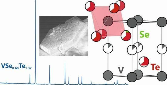
2.1. Crystal Structure Description of VwSeyTe2−y

The VwSeyTe2−y compounds were obtained as gray, crystalline powders from ceramic syntheses, as described in Section 3.1. V1.13Se0.72Te1.28 and V1.10Se0.42Te1.58 crystallize with one structural formula per unit cell in the CdI2-type belonging to the trigonal space group P 3 ¯ m1 (no. 164) [7]. As already alluded, CdI2-type structures are known for their layered appearance consisting of layers of octahedrally coordinated metal ions. These layers were held together by van-der-Waals interactions. Figure 2 shows the unit cells as derived from single-crystal structure determination, as well as the layered structures.
In both structures, vanadium ions that are octahedrally coordinated by selenium or tellurium ions, respectively, reside on the Wyckoff site 1a (V1, 0 0 0). Additionally, Wyckoff site 1b (V2, 0 ½ 0) is occupied by vanadium ions by 13% in the case of V1.13Se0.72Te1.28 (a) and 10% in the case of V1.10Se0.42Te1.58 (b); the Se atom was found to be a little closer to the fully occupied layer formed by V1 than Te. In more detail, the selenium and tellurium ions coordinating the vanadium ions are located on the Wyckoff site 2d (⅓ ⅔ z) with z = 0.235(3) for selenium and z = 0.265(1) for tellurium in V1.13Se0.72Te1.28. In V1.10Se0.42Te1.58, the selenium and tellurium z positions were 0.214(3) and 0.266(1), respectively. The results of the single-crystal refinements are summarized in Table 1, and the refined Wyckoff sites are listed in Table S1.
It is worth mentioning that VS4 is a promising material for magnesium ion batteries with an interchain spacing of 5.83 Å [20]. As the distances between the fully occupied vanadium layers are 6.29 Å and 6.36 Å for V1.13Se0.72Te1.28 and V1.10Se0.42Te1.58, respectively, it may well be the case that the V-Se-Te mentioned above phases may serve well in such magnesium ion batteries, since these distances appear to be large enough for Mg intercalation and deintercalation.

2.2. Elemental Analysis by Means of Energy-Dispersive X-ray Diffraction

The elemental compositions were analyzed by energy-dispersive X-ray spectroscopy (EDX) measurements of the isolated single crystals using a scanning electron microscope (SEM). The SEM images of both crystals are shown in Figure 3. The averaged elemental composition of the V1.13Se0.72Te1.28 specimen analyzed from four single-crystal locations (white rectangles) was 30.7(4) at% vanadium, 27.0(4)% selenium, and 42.3(3)% tellurium. The vanadium content, according to the EDX data, was lower compared to findings from the single-crystal XRD analysis. Seemingly, this is due to the partial overlap of the vanadium Lα1, and Lβ1 signals with the oxygen Kα1 peak, which was found to be a surface artefact [21]. The Se/Te ratio determined from the single-crystal XRD measurement was 0.56, which is close to the EDX value of 0.64. The EDX analysis thus confirmed the composition of the newly synthesized phase, at least semi-quantitatively.
For the crystal with the stoichiometry V1.10Se0.42Te1.58, the EDX measurement also supports the finding of a lower selenium content. Again, the four-spot single-crystal composition was found as 34.7(2) at% vanadium, 9.4(3)% selenium, and 55.9(3)% tellurium. Clearly, the selenium content determined is lower than the single-crystal X-ray diffraction value, and we suspect the presence of tellurium-richer regions closer to the crystal surface. As EDX probes in a region of approximately 2 μm in depth, this might influence the results of this measurement [21]. Carbon artefacts were found in all EDX analyses. This contribution is a known effect for measurements on a carbon adhesive tape and was therefore neglected in the data evaluation.

2.3. Powder X-ray Diffraction Analysis of Compounds in the V–Se–Te System

Compounds with the refined compositions of VSe0.45Te1.55, VSe0.53Te1.47, VSe0.64Te1.36, VSe0.72Te1.28, VSe0.77Te1.23, VSe0.82Te1.18, and VSe0.94Te1.06 were synthesized as described in Section 3.1. All obtained products were gray and polycrystalline. Powder X-ray diffraction was performed as described in Section 3.3, and the data were Rietveld-refined using the FullProf suite [22,23]. A solution of the single-crystal structure of V1.13Se0.72Te1.28 was used as the starting model. The chemical composition of tellurium and selenium were refined individually for each stoichiometry with the coefficient sum fixed at 2. The RBragg values (%) for the samples were 6.90, 3.60, 3.61, 3.36, 4.10, 4.50, and 9.44 in order of increasing Se content.
Interestingly, the preferred orientation of the crystal to the (001) plane was observed, so the G1 parameter was refined to values between 0.27 and 0.40, indicating the platy texture of the crystallites. This matches the shape of the hexagonal single crystals and reflects the layered structure of the material, which is also known for related compounds such as VTe2 [12]. Figure 4 shows the powder pattern of VSe0.72Te1.28 with corresponding Rietveld refinement.
Figure 5 depicts the powder-XRD patterns of the VSeyTe2−y samples with different stoichiometries, with all reflections attributable to the respective Miller indices. With increasing tellurium content, we observed a shift towards lower 2θ values due to the lattice expansion satisfying the spatial requirement of the tellurium anion.
To describe the lattice parameters and the resulting unit-cell volume of similar mixed-ion compounds of the same space group, Vegard’s law can be employed [24,25], relating the lattice parameters of mixed crystals to the lattice parameters of the corresponding pure solids weighted by the molar fraction of the respective constituent. For the ternary vanadium chalcogenides, Vegard’s law is applicable when comparing VSe2 with 1T-VTe2 [7,9]. Figure 6 shows the correlation between the unit cell volume and the tellurium content of the powder samples.
As expected, the unit-cell volume increases with increasing tellurium content, which is explained by the larger ionic radius of tellurium (2.21 Å for coordination number = 6) compared to selenium (1.98 Å for CN = 6) and thus an increase in spatial requirement [26]. The linear fit describes the experimental volumes well; therefore, Vegard’s law applies to this system. Furthermore, the predicted unit cell volume of 59.7 ų for pure VSe2 corresponds to the experimental findings by Wiegers (59.67 ų) [7].

2.4. Magnetic Measurements of VSe0.72Te1.28

The magnetic data of VSe0.72Te1.28 normalized to one formula unit are shown in Figure 7 as a χmT vs. T plot at 0.1 T, and as a Mm vs. H plot at 2.0 K. At 300 K, χmT was 0.25 cm3 K mol–1, which is well below the range of 0.34–0.38 cm3 K mol−1 expected [27] from an isolated vanadium(IV) center. Upon cooling the compound, χmT almost linearly decreased to 0.083 cm3 K mol−1 at 17 K and subsequently dropped to 0.054 cm3 K mol−1 at 2.8 K. At 2.0 K, the molar magnetization continuously increased with the applied magnetic field. At 50 kOe, the Mm vs. H curve is characterized by a distinct slope and the value Mm = 0.09 NA μB. Both observations show that the magnetization was far from being saturated under these conditions. E.g., the saturation value is Mm,sat = gS NA μB ≈ 1.0 NA μB for a vanadium(IV) center with the valence electron configuration 3d1, an effective g value of g ≈ 2.0, and spin S = ½.
Even though a slight deviation from the spin-only value of χmT = 0.375 cm3 K mol−1 (S = ½) is expected for a 3d1 center even in a perfect octahedral ligand field, since contributions from the orbital momentum are not fully quenched, the found value at 300 K is beyond such an explanation. However, the value of 0.25 cm3 K mol−1, as well as the distinct slope of the χmT vs. T curve over the entire measured temperature range (instead of being almost constant), indicate predominantly strong antiferromagnetic exchange interactions between the vanadium centers. This conclusion is also supported by the magnetization data at 2.0 K, as strong antiferromagnetic interactions result in the observed and above– discussed features of the Mm vs. H curve.

2.5. Thermal Analyses of VSe0.72Te1.28

In a nitrogen atmosphere, the VSe0.72Te1.28 sample showed an endothermic DSC peak at a temperature of 850 °C, while a mass loss was observed in TGA (Figure 8). At the same temperature and after the main mass loss, a second event with a slight increase in mass was observed, indicating the formation of a new phase with the surrounding gas. The powder XRD analysis of the thermally treated sample indicated that the sample had partially decomposed and formed VN (Figure S1) [28,29]. As a reaction equation, we suggest (1).
2   VSe 0.72 Te 1.28 s + ½   N 2 g VN s + VSe s + 0.44   Se g + 2.56   Te g
With increasing temperature, an exothermic signal, most likely due to thermal expansion of the powdery sample, was observed. This rearrangement may result in closer packing. While the literature reports that VN forms at 1100 °C, we detect a partial decomposition already at a 250 °C lower temperature [30,31]. The total mass loss was approximately 14%.
In the argon atmosphere, the VSe0.72Te1.28 had a total mass loss of 33%. After the experiment, the glass tube inside the furnace exhibited thin orange and gray layers (Figure S2). It was assumed that tellurium and red selenium were deposited in the colder parts of the tube. The analysis of the collected powder XRD pattern showed decomposition of the sample to mainly VSe and VTe as minor phases. A Rietveld refinement revealed 25% VSe with RBragg = 9.89% and 75% VTe with RBragg = 13.9%. The corresponding pattern are shown in Figure S3.
Initial investigations at low temperatures show no obvious structural changes in VSe0.72Te1.28 down to 30 K. The collected powder pattern is shown in Figure S4.

3. Materials and Methods

3.1. Syntheses

Ceramic syntheses were carried out starting from pure vanadium (99.5%, Alfa Aesar, Ward Hill, MA, USA), selenium (99.999%, MaTeck, Jülich, Germany), and tellurium (≥99.7%, Fluka AG, Buchs, Switzerland) in stoichiometric quantities (≈300 mg per experiment) in evacuated quartz glass ampoules (length 9 cm, diameter 0.7 cm from GVB GmbH—Solutions in Glass, Herzogenrath, Germany) in a horizontal self-built tube furnace controlled by model 3216 from Eurotherm Germany GmbH (Limburg an der Lahn, Germany) or by model ETC 442 from ENDA (SİSEL MÜHENDİSLİK ELEKTRONİK SAN. VE TİC. A.Ş., Istanbul, Turkey). The applied temperature program involved heating to 800 °C with at a rate of 80 °C h−1, holding this temperature for 120 h, and subsequently quenching in ice water for all phases. The reaction products were gray, metallically lustering powders containing small crystals that were isolated and analyzed by single-crystal X-ray diffraction experiments. Thus far, the powders appear to be stable in air for at least one year.
It is most likely that the remaining tellurium in Figure 4 is due to a slightly longer ampoule in which selenium had more space to deposit on the glass as a pure element. Hence, the stoichiometry changed, creating an excess of tellurium. Removing the excess tellurium from the product powder turned out to be difficult. Heating the sample to evaporate the tellurium was impossible because of sample decomposition. Pure tellurium did not dissolve either in orthophosphoric acid (85%), sulfuric acid (≥95%), or hydrochloric acid (37%). Nitric acid (65%) dissolved pure tellurium immediately, as well as the sample as well, which then turned green. All acids were purchased from Fisher Scientific GmbH (Hagen, Germany, part of Thermo Fisher Scientific Inc., Waltham, MA, USA).

3.2. Single-Crystal X-ray Diffraction Experiments and Structure Resolution

Single-crystal X-ray diffraction experiments were performed on a Bruker APEX II diffractometer (Bruker Corporation, Billerica, MA, USA) with Mo-Kα (λ = 0.71073 Å) radiation using a CCD detector. Integration and absorption correction of the experimental data were performed using APEX2 [32]. The structures were solved and refined using direct methods using WinGX 2023.1 [33] and SHELXL 2018/1 [34,35,36]. The well-resolved data allowed for the refinement of the fully occupied V1 (1a) and sub-occupied V2 (1b) positions with independent anisotropic displacement parameters (ADPs). Because the Se and Te essentially occupy the same (2b) site, with only a small displacement difference of about 0.33 Å (V1.10Se0.42Te1.58) and 0.19 Å (V1.13Se0.72Te1.28), their site-occupation factors were coupled to full occupancy for the 2b site. The larger displacement difference in V1.10Se0.42Te1.58 allowed for the refinement of Se and Te with individual ADPs, whereas, in V1.13Se0.72Te1.28, a common ADP set for Se and Te atoms was used. Full details concerning the structure determinations are available in the CIF format and have been deposited as CCDC 2306778 and 2306779. These data can be obtained free of charge via www.ccdc.cam.ac.uk/data_request/cif, by emailing [email protected], or by contacting The Cambridge Crystallographic Data Centre, 12 Union Road, Cambridge CB2 1EZ, UK; fax: +44-1223-336033.

3.3. Powder X-ray Diffraction Experiments and Refinement

To obtain powder X-ray diffraction data, the gray reaction products were mechanically ground, placed between Mylar sheets with the aid of grease, and then sealed in sample holders. Powder X-ray diffraction analysis was performed on a STADI P powder diffractometer (STOE & CIE GmbH, Darmstadt, Germany) equipped with a DECTRIS® MYTHEN detector and Ge single-crystal monochromator with Cu-Kα1 radiation (λ = 1.54059 Å). Powder X-Ray diffraction measurements were controlled with the aid of the WinXPow software (version 3.7.0.0) [37].
Data refinement was performed using the Rietveld method with the FullProf suite [22], starting with a model derived from the single-crystal structure refinement of V1.13Se0.72Te1.28.
Low temperature data were collected using a Huber G670 powder diffractometer (HUBER Diffraktionstechnik GmbH & Co. KG, Rimsting, Germany) equipped with a copper X-ray tube in combination with a Ge Huber 616.2 monochromator.

3.4. Scanning Electron Microscopy (SEM) with Energy-Dispersive X-ray Spectroscopy Measurements (EDX)

Energy-dispersive X-ray spectroscopy (EDX) measurements were performed using a Leo Supra 35 VP scanning electron microscope (SEM) from Carl Zeiss AG (Oberkochen, Germany). Using an acceleration voltage of 10 kV, the measurements were performed using an INCA Energy 200 spectroscope with a SiLi crystal (133 eV, 10 mm2) from Oxford Instruments (Abingdon, UK). For the measurement, the sample was deposited on a carbon sticky tape attached to an aluminium holder.

3.5. Measurements of the Magnetic Properties

A Quantum Design DynaCool physical property measurement system (PPMS) (Quantum Design International, Inc., San Diego, CA, USA) was used for vibrating sample magnetometry (VSM) option. A polycrystalline sample of VSe0.77Te1.23 was immobilized using a polypropylene sample capsule and a brass holder. The data were measured as a function of temperature (2–300 K at 0.1 T) and magnetic field (0.1–5 T at 2 K), then corrected for the diamagnetic contributions of the sample holder and the compound (χm,dia = −1.37 × 10⁻⁴ cm3 mol−1).

3.6. Thermal Analyses of VSe0.72Te1.28

The investigation at elevated temperatures was performed using simultaneous thermal analysis (STA), which combines thermogravimetric analysis (TGA) and differential scanning calorimetry (DSC). The experiments were conducted using STA PT1600 from LINSEIS Messgeräte GmbH (Selb, Germany). Measurements were performed in a nitrogen 5.0 atmosphere, and the samples were placed into Al2O3 crucibles covered with a perforated lid. The applied temperature program involved heating to 1100 °C at a rate of 10 °C h−1 and holding this temperature for 20 min.
For the experiment under argon, the sample was placed in the same kind of crucible, weighted, and transferred into a TF1 12/60/300 furnace (Carbolite Gero GmbH & Co. KG, Neuhausen, Germany, part of VERDER SCIENTIFIC GmbH & Co. KG, Haan, Germany). After evacuating the system and flushing it three times with argon 4.8, the same temperature program was applied. The cooled samples were then weighted again.

4. Conclusions

The new ternary compounds exhibited similar structures to the already known V1.04Se2 phase and a high-temperature modification of VTe2 [8,9]. The selenium and tellurium atoms occupy the Wyckoff site 2d, and the lattice parameters were found to lie between those of the structures of the binaries. The powder diffractograms of seven compounds with different stoichiometries within the VwSeyTe2−y system show the expected trend, namely that is, a larger tellurium content leads to a shift in the reflection positions to lower 2θ values.
Simultaneous DSC/TGA measurements in a nitrogen atmosphere revealed an endothermic decomposition of VN at temperatures above approximately 850 °C. In the argon atmosphere, the sample decomposed into VSe and VTe. The magnetic measurements show predominantly strong antiferromagnetic coupling.

Supplementary Materials

The following supporting information can be downloaded at: https://www.mdpi.com/article/10.3390/inorganics11120481/s1, Table S1: Spatial parameters in V1.13Se0.72Te1.28 and V1.10Se0.42Te1.58; Figure S1: Comparison of VSe0.72Te1.28 powder X-ray data after synthesis, after DSC/TGA, and Bragg positions of VSe and VN; Figure S2: Glass tube of the furnace with orange and gray layers after heating in argon atmosphere; Figure S3: Rietveld refinement of the VSe0.72Te1.32 powder after being heated in argon atmosphere; Figure S4: Comparison of VSe0.72Te1.28 powder X-ray data at room temperature and at 30 K.

Author Contributions

Conceptualization S.K.; methodology S.K., A.F., B.V.H. and J.v.L.; validation J.v.L. and R.D.; formal analysis F.K., S.K., A.F. and J.v.L.; investigation F.K., S.K., A.F. and B.V.H.; resources B.V.H., A.F., K.F. and R.D.; data curation S.K.; writing—original draft preparation F.K. and S.K.; writing—review and editing S.K., F.K., A.F., B.V.H., J.v.L., K.F. and R.D.; visualization F.K., S.K. and J.v.L.; supervision K.F. and R.D.; project administration, S.K., K.F. and R.D.; funding acquisition K.F. and R.D. All authors have read and agreed to the published version of the manuscript.

Funding

This research was funded by the German Research Foundation (DFG, Bonn, Germany; SFB 917 “Nanoswitches”; S.K., B.V.H., K.F., and R.D.).

Data Availability Statement

The crystallographic data of V1.10Se0.42Te1.58 and V1.13Se0.72Te1.28 are provided in separate CIF files (can be found in Supplementary Materials).

Acknowledgments

The authors thank Tobias Storp for the collection of powder and single-crystal X-ray diffraction data, Birgit Hahn for EDX measurements, Kai Fries for performing the decomposition reaction under argon, Shibabrata Nandi and Hend Shahed for their assistance with the PPMS measurements, and Yannick Meinerzhagen and Nils Kurig for fruitful discussions about crystallographic problems.

Conflicts of Interest

The authors declare no conflict of interest.

References

  1. Dunn, J.P.; Stenger, H.G.; Wachs, I.E. Oxidation of SO2 over Supported Metal Oxide Catalysts. J. Catal. 1999, 181, 233–243. [Google Scholar] [CrossRef]
  2. Sanap, P.P.; Gupta, S.P.; Kahandal, S.S.; Gunjakar, J.L.; Lokhande, C.D.; Sankapal, B.R.; Said, Z.; Bulakhe, R.N.; Man Kim, J.; Bhalerao, A.B. Exploring vanadium-chalcogenides toward solar cell application: A review. J. Ind. Eng. Chem. 2023, 129, 124–142. [Google Scholar] [CrossRef]
  3. Yang, X.; Zhang, Z. Carbon-coated vanadium selenide as anode for lithium-ion batteries and sodium-ion batteries with enhanced electrochemical performance. Mater. Lett. 2017, 189, 152–155. [Google Scholar] [CrossRef]
  4. Hoschek, E.; Klemm, W. Vanadinselenide. Z. Anorg. Allg. Chem. 1939, 242, 49–62. [Google Scholar] [CrossRef]
  5. Ehrlich, P. Über die binären Systeme des Titans mit den Elementen Stickstoff, Kohlenstoff, Bor und Beryllium. Z. Anorg. Chem. 1949, 259, 1–41. [Google Scholar] [CrossRef]
  6. Biltz, W.; Köcher, A. Beiträge zur systematischen Verwandtschaftslehre. 88. Über das System Vanadium/Schwefel. Z. Anorg. Allg. Chem. 1939, 241, 324–337. [Google Scholar] [CrossRef]
  7. Wiegers, G.A. Physical properties of first-row transition metal dichalcogenides and their intercalates. Phys. B C 1980, 99, 151–165. [Google Scholar] [CrossRef]
  8. Nakahira, M.; Hayashi, K. Characterization of the layered transition-metal dichalcogenides with octahedral coordination. Mat. Res. Bull. 1978, 13, 1403–1408. [Google Scholar] [CrossRef]
  9. Bronsema, K.D.; Bus, G.W.; Wiegers, G.A. The crystal structure of vanadium ditelluride, V1+xTe2. J. Solid State Chem. 1984, 53, 415–421. [Google Scholar] [CrossRef]
  10. van Bruggen, C.F.; Haas, C. Magnetic susceptibility and electrical properties of VSe2 single crystals. Solid State Commun. 1976, 20, 251–254. [Google Scholar] [CrossRef]
  11. DiSalvo, F.J.; Waszczak, J.V. Magnetic studies of VSe2. Phys. Rev. B 1981, 23, 457–461. [Google Scholar] [CrossRef]
  12. Won, D.; Kiem, D.H.; Cho, H.; Kim, D.; Kim, Y.; Jeong, M.Y.; Seo, C.; Kim, J.; Park, J.-G.; Han, M.J.; et al. Polymorphic Spin, Charge, and Lattice Waves in Vanadium Ditelluride. Adv. Mater. 2020, 32, 1906578. [Google Scholar] [CrossRef]
  13. Duvjir, G.; Jung, J.-A.; Ly, T.T.; Lam, N.H.; Chang, Y.J.; Lee, S.; Kim, H.; Kim, J. Fine structure of the charge density wave in bulk VTe2. APL Mater. 2022, 10, 111102. [Google Scholar] [CrossRef]
  14. Huang, Z.-L.; Bensch, W.; Benea, D.; Ebert, H. Anion substitution effects on structure and magnetism in the chromium chalcogenide Cr5Te8—Part I: Cluster glass behavior in trigonal Cr(1+x)Q2 with basic cell (Q = Te, Se; Te:Se = 7:1). J. Solid State Chem. 2004, 177, 3245–3253. [Google Scholar] [CrossRef]
  15. Lotgering, F.K.; Gorter, E.W. Solid solutions between ferromagnetic and antiferromagnetic compounds with NiAs structure. J. Phys. Chem. Solids 1957, 3, 238–249. [Google Scholar] [CrossRef]
  16. Tsubokawa, I. The Magnetic Properties of Chromium-Tellurium-Selenium System. J. Phys. Soc. Jpn. 1956, 11, 662–665. [Google Scholar] [CrossRef]
  17. Wontcheu, J.; Bensch, W.; Mankovsky, S.; Polesya, S.; Ebert, H.; Kremer, R.K.; Brücher, E. Anion substitution effects on the structure and magnetism of the chromium chalcogenide Cr5Te8—Part III: Structures and magnetism of the high-temperature modification Cr(1+x)Q2 and the low-temperature modification Cr(5+x)Q8 (Q = Te, Se; Te:Se = 5:3). J. Solid State Chem. 2008, 181, 1492–1505. [Google Scholar] [CrossRef]
  18. Arnaud, Y.; Chevreton, M. Etude comparative des composés TiX2 (X = S, Se, Te). Structures de TiTe2 et TiSeTe. J. Solid State Chem. 1981, 39, 230–239. [Google Scholar] [CrossRef]
  19. Rimmington, H.P.B.; Balchin, A.A. The growth by iodine vapour transport techniques and the crystal structures of layer compounds in the series TiSxSe2−x, TiSxTe2−x, TiSexTe2−x. J. Cryst. Growth 1974, 21, 171–181. [Google Scholar] [CrossRef]
  20. Dey, S.; Lee, J.; Britto, S.; Stratford, J.M.; Keyzer, E.N.; Dunstan, M.T.; Cibin, G.; Cassidy, S.J.; Elgaml, M.; Grey, C.P. Exploring Cation–Anion Redox Processes in One-Dimensional Linear Chain Vanadium Tetrasulfide Rechargeable Magnesium Ion Cathodes. J. Am. Chem. Soc. 2020, 142, 19588–19601. [Google Scholar] [CrossRef]
  21. Goldstein, J.I.; Newbury, D.E.; Michael, J.R.; Ritchie, N.W.M.; Scott, J.H.J.; Joy, D.C. Scanning Electron Microscopy and X-ray Microanalysis, 4th ed.; Springer: New York, NY, USA, 2017. [Google Scholar]
  22. Rodríguez-Carvajal, J. Recent advances in magnetic structure determination by neutron powder diffraction. Phys. B: Condens. Matter. 1993, 192, 55–69. [Google Scholar] [CrossRef]
  23. Rodríguez-Carvajal, J. Recent developments of the program FULLPROF. Comm. Powder Diffr. (IUCr) Newsl. 2001, 26, 12. [Google Scholar]
  24. Vegard, L. Die Konstitution der Mischkristalle und die Raumfüllung der Atome. Z. Phys. 1921, 5, 17–26. [Google Scholar] [CrossRef]
  25. Goldschmidt, V.M. Die Gesetze der Krystallochemie. Naturwissenschaften 1926, 14, 477–485. [Google Scholar] [CrossRef]
  26. Shannon, R. Revised effective ionic radii and systematic studies of interatomic distances in halides and chalcogenides. Acta Crystallogr. A 1976, 32, 751–767. [Google Scholar] [CrossRef]
  27. Lueken, H. Magnetochemie; Teubner Verlag: Stuttgart, Germany, 1999. [Google Scholar]
  28. Sakuma, T.; Xianglian; Siagian, S.; Basar, K.; Takahashi, H.; Igawa, N.; Kamishima, O. Correlation effects among thermal displacements of atoms in VSe by diffuse neutron scattering measurement. J. Therm. Anal. Calorim. 2010, 99, 173–176. [Google Scholar] [CrossRef]
  29. Sharygin, V.V.; Ripp, G.S.; Yakovlev, G.A.; Seryotkin, Y.V.; Karmanov, N.S.; Izbrodin, I.A.; Grokhovsky, V.I.; Khromova, E.A. Uakitite, VN, a New Mononitride Mineral from Uakit Iron Meteorite (IIAB). Minerals 2020, 10, 150. [Google Scholar] [CrossRef]
  30. Lengauer, W.; Ettmayer, P. Lattice parameters and thermal expansion of δ-VN1−x from 298–1000 K. Monatsh. Chem. 1986, 117, 713–719. [Google Scholar] [CrossRef]
  31. Ettmayer, P.; Schebesta, W.; Vendl, A.; Kieffer, R. Beitrag zur Kenntnis des Systems Vanadin—Chrom—Stickstoff. Monatsh. Chem. 1978, 109, 929–941. [Google Scholar] [CrossRef]
  32. APEX2, v2014.11-0; Bruker AXS: Madison, WI, USA, 2015.
  33. Farrugia, L. WinGX and ORTEP for Windows: An update. J. Appl. Cryst. 2012, 45, 849–854. [Google Scholar] [CrossRef]
  34. Sheldrick, G. A short history of SHELX. Acta Crystallogr. A 2008, 64, 112–122. [Google Scholar] [CrossRef]
  35. Sheldrick, G. Crystal structure refinement with SHELXL. Acta Crystallogr. C 2015, 71, 3–8. [Google Scholar] [CrossRef]
  36. Sheldrick, G. SHELXT–Integrated space-group and crystal-structure determination. Acta Crystallogr. A 2015, 71, 3–8. [Google Scholar] [CrossRef]
  37. WinXPOW Powder Diffraction Software, 3.7.0.0; STOE & Cie GmbH: Darmstadt, Germany, 2021.
Figure 1. (a) Crystal structure of VSe2 from powder XRD [7]. (b) Crystal structure of V1.04Se2 from single-crystal XRD [8]. (c) Crystal structure of VTe2 from powder XRD [9]. Vanadium atoms are gray, selenium is green, and tellurium is red. Sub-occupied vanadium atoms are given in light gray.
Inorganics 11 00481 g001
Figure 2. Crystal structure of (a) V1.13Se0.72Te1.28 and (b) V1.10Se0.42Te1.58 as derived from single-crystal XRD analysis; (c) layered structure of V1.13Se0.72Te1.28. Vanadium atoms are gray, selenium is green, and tellurium is red. Sub-occupied vanadium atoms are given in light gray.
Inorganics 11 00481 g002
Figure 3. Scanning electron microscopy images of the isolated (a) V1.13Se0.72Te1.28 and (b) V1.10Se0.42Te1.58 single crystals. The white rectangles indicate where EDX measurements were performed.
Inorganics 11 00481 g003
Figure 4. Rietveld refinement of the VSe0.72Te1.32 powder with measured data in red, simulated pattern in black, Bragg positions in green, and the difference between measured and calculated pattern in blue. One reflection of remaining tellurium at 27° was excluded in the refinement.
Inorganics 11 00481 g004
Figure 5. Powder XRD patterns of the VSeyTe2−y samples with different stoichiometries. Increasing tellurium content is marked in darker color tones. Samples from which single crystals were isolated are shown in blue (V1.13Se0.72Te1.28) and red (V1.10Se0.42Te1.58).
Inorganics 11 00481 g005
Figure 6. Unit cell volume of the synthesized ternary V–Se–Te compounds in space group P 3 ¯ m1 depending on their tellurium content in blue and literature data for VSe2 and VTe2 in black [7,9].
Inorganics 11 00481 g006
Figure 7. (a) Temperature dependence of χmT of VSe0.72Te1.28 at 0.1 T, (b) molar magnetization Mm vs. applied magnetic field H at 2.0 K.
Inorganics 11 00481 g007
Figure 8. Thermogravimetric analysis and differential scanning calorimetry of VSe0.72Te1.28 in a nitrogen atmosphere with the percentage of mass loss in red and heat flow in black.
Inorganics 11 00481 g008
Table 1. Refinement details of the single-crystal studies of V1.13Se0.72Te1.28 and V1.10Se0.42Te1.58.
FormulaV1.13Se0.72Te1.28V1.10Se0.42Te1.58
form wt. (g mol−1)277.74290.81
space group P 3 ¯ m1 P 3 ¯ m1
a (Å)3.626(2)3.633(7)
c (Å)6.290(2)6.365(12)
volume (Å3)71.6(1)72.7(3)
Z11
calc. density (g cm−3)6.4416.639
µ (mm−1)25.54124.140
F(000)117122
θ range (°)3.24–30.403.20–31.00
index range−5 ≤ h ≤ 4
−5 ≤ k ≤ 5
−8 ≤ l ≤ 8
−5 ≤ h ≤ 4
−4 ≤ k ≤ 5
−9 ≤ l ≤ 7
reflections collected1049585
independent reflections108111
refinement methodFull matrix least squares on F2
data/restraints/parameters108/0/11111/0/14
goodness-of-fit on F21.2080.987
final R indices [I > 2σ(I)]R1 = 0.021; wR2 = 0.049 R1 = 0.020; wR2 = 0.042
R indices (all data)R1 = 0.023; wR2 = 0.050R1 = 0.021; wR2 = 0.042
Rint0.0250.029
largest diff. peak and hole (eÅ−3)1.454 and −1.1980.807 and −0.904
Disclaimer/Publisher’s Note: The statements, opinions and data contained in all publications are solely those of the individual author(s) and contributor(s) and not of MDPI and/or the editor(s). MDPI and/or the editor(s) disclaim responsibility for any injury to people or property resulting from any ideas, methods, instructions or products referred to in the content.

