Sculpture from Patchwise Modules

College of Computing and Digital Media, Depaul University, Chicago, IL 60604, USA
Mathematics 2019, 7(2), 197; https://doi.org/10.3390/math7020197
Submission received: 1 December 2018
/
Revised: 14 January 2019
/
Accepted: 26 January 2019
/
Published: 19 February 2019
(This article belongs to the Special Issue Topological Modeling)
Abstract
:The sculptor adapts the geometry of spline surfaces commonly used in 3D modeling programs in order to translate some of the topological nature of these virtual surfaces into his sculpture. He realizes the patchwise geometry of such surfaces by gluing square modules of neoprene rubber edge to edge to define the surface which he then torques and bends into sculptures. While limited by the nature of actual materials, the finished sculptures successfully incorporate the expressive tension and flow of forms sought by the sculptor. He presents images of finished works and provides an analysis of the emotive values of a select sculpture.
1. Introduction
The depiction of topological surfaces in the rigid materials of traditional sculpture was an early pursuit of modern abstract art [1,2] and today still remains a fixture in many examples of mathematical sculpture (Figure 1). Topological concepts have also been a trigger for advanced explorations by less mathematical sculptors.
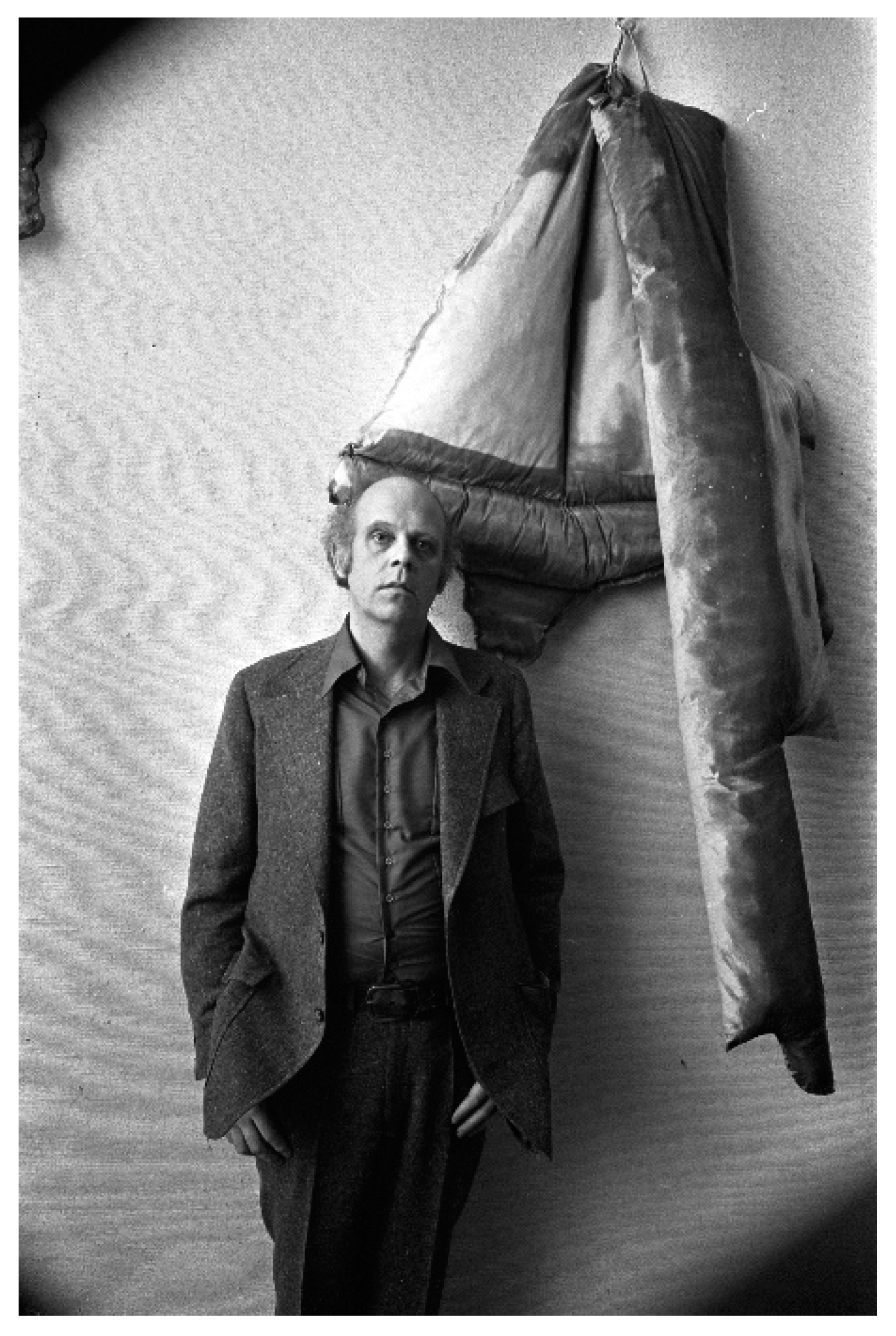
During the 1970s, Post-Minimalist sculptures such as those by Eva Hesse [3] and Robert Morris [4] broke the stark reins of Minimalism in part by turning to soft industrial materials such as latex and felt in lieu of metal and rigid plastics. Best known were the soft sculptures of common objects by Claes Oldenberg (Figure 2) [5].
2. Previous Work
There are many sculptors who create topologically interesting sculptures by developing their own methods. Some of us, such as Heleman Ferguson [6,7], George Hart [8,9,10,11,12], Nat Friedman [13,14,15,16] Charles Perry [17,18,19], James Mallos [20,21,22,23,24], Henry Segerman [25,26], Rinus Roelofs [27,28,29,30,31,32], David Reinmann [33,34], and myself [35,36,37,38,39,40,41,42,43] share our methods by publishing papers in conferences, journals, and magazines.
However, there are also many sculptors who intuitively create new topologically interesting forms and do not publish and explain how they created these forms. Some of these artists’ works have been studied by mathematicians. We can find publications on the mathematical aspects of sculptures of Bruce White [44], Robert Morris [45], Robert Longhurst [46,47], Anish Kapoor [48,49,50], Larry Frazer [51], Charles Ginnever, [52], Bathsheba Grossman [53,54,55] Tony Smith [4,56], Richard Serra [4,57], Keizo Ushio [58], Brent Collins [59,60,61], Carlos Sequin [62,63,64] Ilhan Koman [65,66], and Eva Hild [67,68,69,70,71].
One of the common methods to construct complicated topological sculptures is to use modular elements. For two-manifold surfaces, the modular construction corresponds to the cellular decomposition of the original surface [72,73]. This decomposition can be used to classify these modular sculptures as physical data structures [12,74], and these physical mesh data structures can be considered instances of thickened graphs embedded on orientable two-manifold surfaces [75].
Many mathematical toys, such as Flexeez, space chips, and ITSPHUN, are also designed to construct such physical data structures [76,77]. Reimann’s sculptures from flexible rectangular modules [33] and George Hart’s modular Krigami sculptures [6] are also examples of such structures. Akleman demonstrated that any two-manifold surface can be constructed by cylindrical quadrilateral modules [76]. In this paper, I present another method for constructing sculptures from rubber sheet modules that can be considered spline patches.
3. Materials and Methods
Topology has sometimes been called “rubber sheet geometry” in contrast to the fixed constraints of Euclidean geometry. No matter how stretched and flexed is a rubber sheet, however, it hardly approaches the ideal properties of a topological sheet. Nonetheless, rubber sheets can demonstrate some of the behavior of a surface as its points and edges loosen and the surface garners greater degrees of freedom. This paper explores the application of neoprene sheeting to fabricate sculptures that display topological effects, albeit in a highly constrained mode.
To this end, the project took its cue from the methods employed by spline surface modeling programs to generate and modify three-dimensional surfaces. The sculptor selected the surface building geometry of patchwise construction featured in the program Rhino 3D (Version 5, Robert McNeel and Associates, Seattle, WA, USA). Specifically, Rhino is known as a non-uniform rational basis spline (NURBS) modeler.
Building sculptures from modules of rubber sheeting is akin to the patchwise computer modeling of 3D surfaces. The transformation of rubber sheets actually conforms more closely to the properties of spline geometry, which describes the bending of material under force, than to pure topology.
3.1. Splines and Patches
The concept behind this investigation borrows from spline geometry’s view of surfaces, which defines a patch as a surface region to varying degrees independent of the rest of the surface, but integrated by principles of continuity with neighboring regions. It uses control points, which the sculptor can drag to different positions thus pulling the surface in a new direction. In addition, the sculptor may increase or decrease the pulling of the surface toward the point by adjusting the weight assigned to each point [78]. The sculptor then controls both the pressure and response actuating a surface and how that response carries over into adjacent patches.
Each surface patch can connect with its neighbors in varying degrees of continuity such that transformations effected by the control point can spread to these neighbors. In the program Rhino, the sculptor can apply surface properties controlling how far this transformation might spread across patches. This property is specified by the degree of the polynomials defining the surface: the higher the degree, the broader the spread. Quadratic equations define a degree 2 surface, whereas cubic equations determine a degree 3 surface. Similarly, quartic and quintic equations are responsible for degree 4 and degree 5 surfaces, respectively.
The spline surface is topologically a rectangular net of m spline curves in one direction and n spline curves perpendicular to the first set (Figure 3). The n × m intersection points between those two sets of spline curves serve as control points to define the shape of the patch. Each point affects both intersecting curves simultaneously to create two directions of curvature for the patch to follow. The two directions are labelled U and V.
Spline geometry provides two properties for transforming the rectangular surface into closed surfaces. First, the surface can curve back on itself such that the opposite edges join on what is termed a seam. The surface is then rendered continuous through this seam as with a cylindrical surface. Second, the longitudinal splines terminating on the open edges of the cylinder can converge on a single point to effect a singularity where all of these splines terminate on the same point. A singularity at each end of the cylinder might transform it into an approximate sphere, as seen with the north–south lines on a world globe.
Spline geometry derives its procedural origins from drafting and its mathematical expressions from the Euler–Bernoulli formulation for the bending of beams under lateral force. Spline curves closely mimic the bending pattern of flexed materials, especially such common materials as wood, metals, plastics, and rubber. Traditionally, a spline was a flexible drafting tool for tracing non-circular curves. The tool was usually a thin, straight-grained length of wood that draftsmen in the ship building industry used to interpolate curves between points that had been previously plotted using compass and straightedge methods. Draftsmen employed heavy metal weights, termed ducks, to fix the spline in place and then adjusted—or faired—the spline to flow as smoothly as possible through the given points (Figure 4). These weights provided the lateral forces to bend the spline.
3.2. Material Constraints
Most flexing materials do so with only single curvature, disallowing most topological features. However, materials, such as rubber, can also stretch to permit double curvature and consequently conform more closely to a spline surface resulting in zero Gaussian curvature.
The sculptures created under this project comprise square neoprene patches, cut by water jet at a gasket-making facility from a sheet whose thickness is 12 mm, 1/25 the width of the 30 cm squares. This proportion follows from specific requirements of the surfaces forming the sculptures. The first requirement is that the patches join one another edge to edge to create tangent continuity between the patches. The glue is a methylacrylate compound (i.e., Super Glue (Super Glue Corporation, Ontario, CA, USA)) commonly employed to glue rubber. The 12 mm thickness allows sufficient glue contact between patch edges, while permitting excellent visual continuity across the seams.
The second requirement is that the surface be stiff enough to retain the form of the sculpture, albeit allowing sufficient flexibility. Again, the 1:25 proportion meets this need. However, this stiffness raises a problem of continuity across vertices.
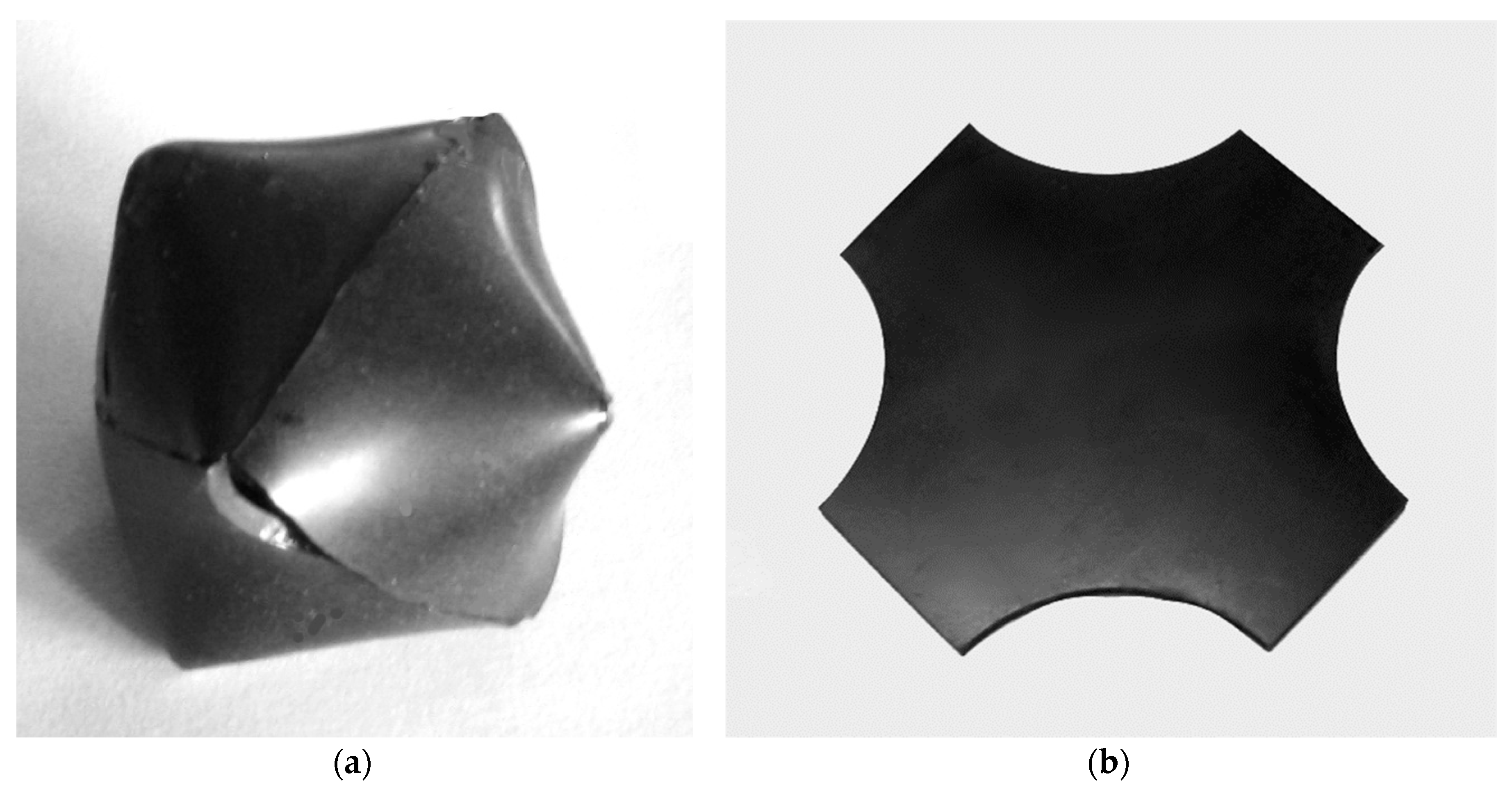
Where three or more patches joined as their edges approach a vertex point, they cannot flex sufficiently to meet at that point and a gap causes an unwanted break in the flow of the surface (Figure 5a). Removing the corners solves this problem, while changing the shape of the patch to resemble a cross (Figure 5b). In this case, the voids were 90° arcs of 10 cm radius. This adaptation of the patch opened the fortunate option of creating circular voids through the surface and into the internal spaces of the sculptures.
4. Results
When compared to the virtual patchwise surfaces, the neoprene representations lacked considerable freedom to transform. The sphere in Figure 3b, for example, is possible because its patches expand at the equator and compress to a point at the poles. The neoprene can do neither. However, it can fold and torque to create physical stresses that can serve to convey a sense of stress within the viewer.
Results are presented here as a gallery of sculptures created under this project. Beginning with sculptures of only two patches, the images go on to illustrate outcomes requiring four and then six patches.
4.1. Two-Patch Surfaces
The results were surprising in how a very few patches could yield surfaces of sculptural interest. For example, only two patches when combined yielded seven sculptures as illustrated in Figure 6. This surface offers six extended edges that fold into one another in several combinations.
4.2. Four-Patch Surfaces
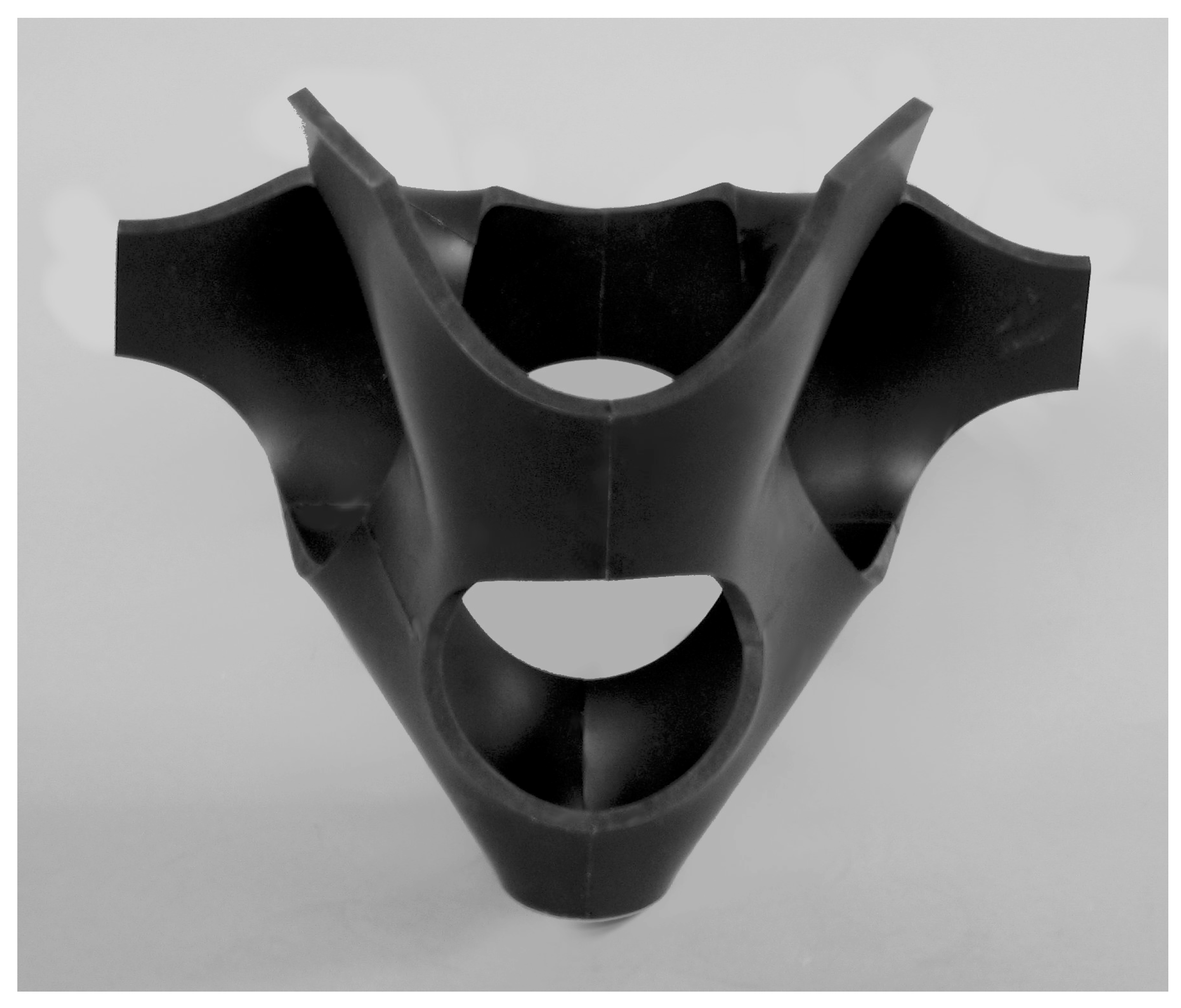
With four patches the sculptures engaged more substantial volumes, as in the sculpture Chamber depicted in Figure 7. The biomorphic effects sought by the sculptor began to appear as the sculptures suggested the shapes of organs. The title Chamber alludes to the terminology applied to organs that function as containers, as in the chambers of the heart.
4.3. Six-Patch Surfaces
The most effective products for this sculptor emerged when surfaces comprised six patches. At that number, the surface patches connected while generating multiple passages that displayed a variety of surface tensions. In addition, the voids created by the corner extractions achieved similar variability.
The pattern taken by the patches formed a cross like the one seen when a cube unfolds. Figure 8 depicts this pattern with two edge flanges joined into a seam. The unfolded cube net provides a total of fourteen edges available for joining to one another. By contrast, a rectangular two by three array of patches would yield only ten edges to be joined, with seven internal seams already formed. In addition, this arrangement allows considerably more suppleness in order to shape sculptures of more engaging complexity.
5. Discussion: Vented Torso
Lucas Cowan, curator of the exhibit Invoking the Absence, chose Vented Torso (Figure 11a,b) for display in the rotunda of the Elks National War Memorial in Chicago. That spring of 2014, Vented Torso found, for a number of reasons, an appropriate home in the famed Beaux Arts sanctuary.
One reason was the strong classical proportions effected by the underlying grid of patches. Additionally, the circular voids generated by the corner extractions of the modules caused a parallel system of proportions to penetrate the sculpture’s surface. The base, for example, is a circle created by joining two patches by their adjacent edges. Just above the base three patches join to enclose two circular voids to flank the base on two sides. The voids expand proportionally as the torso widens through its chest. This third level of holes is formed by two rings of four patches. The last two voids open to the left and right as one arm of each patch flanges outward, suggesting the cropped arms of classic torsos. A skewed connection of two opposite patches at the top of the torso introduces a twist suggesting the classic contrapposto pose of ancient Greek figure sculpture.
The play between flexibility and stiffness in the neoprene patches yields curvature and torsion, which together suggest a twisting torso. The industrial nature of the material also implies body armor—in fact, many viewers saw it as a symbol of damaged body armor. a fitting theme for the purpose of the memorial. One might conceive the sculpture as an abstraction of the torso in the same sense as armor fitted to the body: it simplifies and smooths over the contours of a soldier’s body. Other sculptures using these neoprene modules followed this same concept by appearing as pieces of armor such as helmets or breastplates.
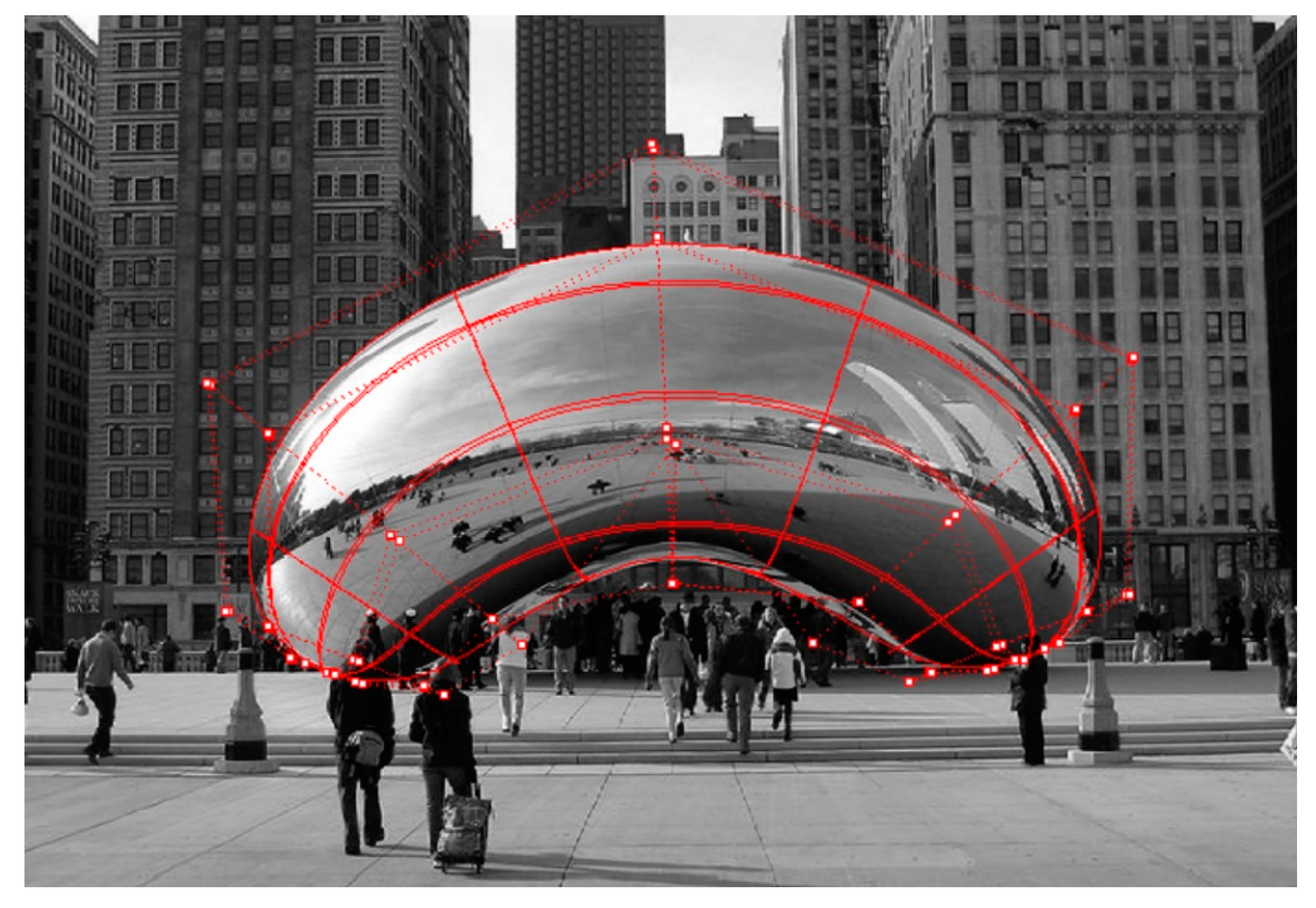
On another level, and one of particular interest to the sculptor, Vented Torso represents a juncture of the geometric and the organic forms. Traditionally, artists have analyzed sculpture into two categories: either geometric or biomorphic with the division relatively distinct. More contemporary applications of geometry, such as patchwise computer modeling, bridge this divide. This has had a profound influence on the work of sculptors like Anish Kapoor, whose application of NURBS geometry has characterized his recent work, most notably Chicago’s famed “Cloud Gate” (Figure 12).
Funding
This research received no external funding.
Conflicts of Interest
The author declares no conflict of interest.
References
- Luecking, S. Mathematics Education and Early Abstract Art. In Proceedings of the Bridges: Mathematics, Music, Art, Architecture, Enschede, The Netherlands, 27–31 July 2013. [Google Scholar]
- Vierling-Claassen, A. Models of surfaces and abstract art in the early 20th century. In Bridges 2010; Springer: Berlin/Heidelberg, Germany, 2010; pp. 11–18. [Google Scholar]
- Berger, M.; Chave, A.C.; Kreutzer, M.; Norden, L.; Storr, R.; Hesse, E. Eva Hesse: A Retrospective; Yale University Art Gallery: New Haven, CT, USA, 1992. [Google Scholar]
- Friedman, N. Hypersculptures by Robert Morris, Tony Smith, Arthur Silverman, Richard Serra, and Charles Ginnever. Hyperseeing. Special Issue on ISAMA’07 Sixth Interdisciplinary Conference of the International Society of the Arts, Mathematics, and Architecture. May 2007, pp. 21–40. Available online: http://www.isama.org/hyperseeing/07/07-05.pdf (accessed on 15 January 2019).
- Oldenburg, C.; Celant, G.; Koepplin, D.; Rosenthal, M.L. Claes Oldenburg: An Anthology; Guggenheim Museum: New York, NY, USA, 1995. [Google Scholar]
- Ferguson, C.; Ferguson, H. Helaman Ferguson: Mathematics in Stone and Bronze; Meridian Creative Group: Erie, PA, USA, 1994. [Google Scholar]
- Helaman, F.; Rockwood, A.; Cox, J. Topological design of sculptured surfaces. Comput. Graph. 1992, 26, 149–156. [Google Scholar]
- Hart, G.W. Sculpture from Symmetrically Arranged Planar Components. In Meeting Alhambra, Proceedings of the ISAMA-Bridges, Granada, Spain, 23–25 July 2003; University of Granada: Granada, Spain, 2003; pp. 315–322. [Google Scholar]
- Hart, G.W. Icosahedral Constructions. In Bridges: Mathematical Connections in Art, Music and Science; Southwestern College: Winfield, KS, USA, 1998. [Google Scholar]
- Hart, G. Modular kirigami. In Bridges Donostia, 2007: Mathematical Connections in Art, Music and Science; Southwestern College: Winfield, KS, USA, 2007; pp. 1–8. [Google Scholar]
- Hart, G. Hyperseeing a Sculpture Based on the (10-3)-a Lattice. Hyperseeing, September 2008; pp. 1–4. Available online: http://www.isama.org/hyperseeing/08/08-e.pdf (accessed on 16 January 2019).
- Hart, G.W. Slide-together: Geometric paper constructions. In Proceedings of the 2004 Bridges Conference on Mathematical Connections in Art, Music, and Science, Winfield, KA, USA, 28 July–1 August 2004. [Google Scholar]
- Friedman, N. Hyperseeing, hypersculptures, and space curves. 1998. Available online: https://www.mi.sanu.ac.rs/vismath/friedman/index.html (accessed on 8 January 2019).
- Friedman, N. Fractal Form and Space. Hyperseeing, March 2007; pp. 7–11. Available online: http://www.isama.org/hyperseeing/07/07-03.pdf (accessed on 8 January 2019).
- Friedman, N. Form, Space and Light. Hyperseeing, July 2007; pp. 1–4. Available online: http://www.isama.org/hyperseeing/07/07-07.pdf (accessed on 3 December 2018).
- Friedman, N. Hypersculptures: Four Right Angles. Hyperseeing, 2011; pp. 13–15. Available online: http://www.isama.org/hyperseeing/11/11a.pdf (accessed on 11 January 2019).
- Friedman, N. Charles Perrry—Ribbed Forms. Hyperseeing, January 2007; pp. 1–3. Available online: http://www.isama.org/hyperseeing/07/07-01.pdf (accessed on 10 January 2019).
- Perry, C. On Mathematical Sculpture. Hyperseeing. Special Issue on ISAMA’08 Seventh Interdisciplinary Conference of the International Society of the Arts, Mathematics, and Architecture. June 2008, pp. 11–20. Available online: http://www.isama.org/hyperseeing/08/08-c.pdf (accessed on 12 January 2019).
- Perry, C.O. On the Edge of Science: The Role of the Artist’s Intuition in Science. Leonardo 1992, 25, 249–252. [Google Scholar] [CrossRef]
- Mallos, J. How to Weave a Basket of Arbitrary Shape. Hyperseeing. Special Issue on ISAMA’09 Eight Interdisciplinary Conference of the International Society of the Arts, Mathematics, and Architecture. June 2009, pp. 13–19. Available online: http://www.isama.org/hyperseeing/09/09b.pdf (accessed on 20 January 2019).
- Mallos, J. Unit-Weave the Cubic Polyhedra. Hyperseeing. Special Issue on ISAMA’09 Eight Interdisciplinary Conference of the International Society of the Arts, Mathematics, and Architecture. June 2009, pp. 113–117. Available online: http://www.isama.org/hyperseeing/09/09b.pdf (accessed on 21 January 2019).
- Mallos, J. Triangle-Strip Knitting. Hyperseeing. Special Issue on ISAMA’10 Nineth Interdisciplinary Conference of the International Society of the Arts, Mathematics, and Architecture. June 2010, pp. 111–116. Available online: http://www.isama.org/hyperseeing/10/10b.pdf (accessed on 9 January 2019).
- Mallos, J. Extra Ways to See: An Artist’s Guide to Map Operations. Hyperseeing. Special Issue on ISAMA’11 Tenth Interdisciplinary Conference of the International Society of the Arts, Mathematics, and Architecture. June 2011, pp. 111–121. Available online: http://www.isama.org/hyperseeing/11/11b.pdf (accessed on 13 January 2019).
- Mallos, J. Zip Crochet: Developing a self-sufficient fabric technique for CAD/CAM surfaces. Hyperseeing. Special Issue on SMI 2013/ISAMA2013, Shape Modeling International 2012 Fabrication and Sculpting Event. June 2013, pp. 51–60. Available online: http://www.isama.org/hyperseeing/13/13a.pdf (accessed on 23 January 2019).
- Segerman, H. Recent 3D Printed Sculptures. Hyperseeing, 2012; pp. 33–38. Available online: http://www.isama.org/hyperseeing/11/11c.pdf (accessed on 10 January 2019).
- Segerman, H. 3D printing for mathematical visualisation. Math. Intell. 2012, 34, 56–62. [Google Scholar] [CrossRef]
- Roelofs, R. Weaving with Concrete. Hyperseeing. Special Issue on SMI 2013/ISAMA2013, Shape Modeling International 2012 Fabrication and Sculpting Event. June 2013, pp. 67–74. Available online: http://www.isama.org/hyperseeing/13/13a.pdf (accessed on 14 January 2019).
- Roelofs, R. Two-and three-dimensional constructions based on Leonardo grids. In Nexus Network Journal; Birkhäuser: Basel, Switzerland, 2008; pp. 17–26. [Google Scholar]
- Roelofs, R. About weaving and helical holes. In Bridges 2010: Mathematics, Music, Art, Architecture, Culture; Tessellations Publishing: Phoenix, AZ, USA, 2010; pp. 75–84. [Google Scholar]
- Roelofs, R. Connected Holes. In Proceedings of the 2008 Bridges Conference on Mathematical Connections in Art, Music, and Science, Leeuwarden, The Netherlands, 24–28 July 2008; pp. 30–38. [Google Scholar]
- Roelofs, R. Three-dimensional and dynamic constructions based on Leonardo grids. Int. J. Space Struct. 2007, 22, 191–200. [Google Scholar] [CrossRef]
- Roelofs, R. Elevations and Stellations. In Bridges 2014; Tessellations Publishing: Phoenix, AZ, USA, 2014; pp. 235–260. [Google Scholar]
- Reimann, D.A. Nonplanar expansions of polyhedral edges in platonic and archimedean solids. In Bridges 2015: Mathematics, Music, Art, Architecture, Culture; Tessellations Publishing: Phoenix, AZ, USA, 2015; pp. 143–150. [Google Scholar]
- Reimann, D.A. Transforming Squares to Strips in Expanded Polyhedral Forms. In Bridges 2017: Mathematics, Music, Art, Architecture, Culture; Tessellations Publishing: Phoenix, AZ, USA, 2017; pp. 435–438. [Google Scholar]
- Luecking, S. Zoomorphs: Hyparhedral and Taut Skin Surfaces in Sculpture. Hyperseeing. Special Issue on ISAMA’10 Nineth Interdisciplinary Conference of the International Society of the Arts, Mathematics, and Architecture. June 2010, pp. 91–102. Available online: http://www.isama.org/hyperseeing/10/10b.pdf (accessed on 17 January 2019).
- Luecking, S. Creating Super-Spheres with Spline Modeling. Hyperseeing. Special Issue on ISAMA’07. Sixth Interdisciplinary Conference of the International Society of the Arts, Mathematics, and Architecture. May 2007, pp. 41–48. Available online: http://www.isama.org/hyperseeing/07/07-05.pdf (accessed on 15 January 2019).
- Luecking, S. Collapsed Orbs: Astroidal Sculptures from the Breakdown of the Sphere. Hyperseeing. Special Issue on ISAMA’09 Eight Interdisciplinary Conference of the International Society of the Arts, Mathematics, and Architecture. June 2009, pp. 57–62. Available online: http://www.isama.org/hyperseeing/09/09b.pdf (accessed on 22 January 2019).
- Luecking, S. Constructing and Tiling Hypar Kites. Hyperseeing. Special Issue on ISAMA’10 Nineth Interdisciplinary Conference of the International Society of the Arts, Mathematics, and Architecture. June 2010, pp. 83–90. Available online: http://www.isama.org/hyperseeing/10/10b.pdf (accessed on 9 January 2019).
- Luecking, S. Octoids: Sculpting Between Octahedron and Sphere. Hyperseeing. Special Issue on ISAMA’11 Tenth Interdisciplinary Conference of the International Society of the Arts, Mathematics, and Architecture. June 2011, pp. 89–91. Available online: http://www.isama.org/hyperseeing/11/11b.pdf (accessed on 11 January 2019).
- Luecking, S. Building a Scherk Surface from Paper Tiles. Hyperseeing. Special Issue on ISAMA’11 Tenth Interdisciplinary Conference of the International Society of the Arts, Mathematics, and Architecture. June 2011, pp. 101–104. Available online: http://www.isama.org/hyperseeing/11/11b.pdf (accessed on 7 January 2019).
- Luecking, S. Sculpture from a Space Filling Saddle Pentahedron. Hyperseeing. Special Issue on ISAMA’11 Tenth Interdisciplinary Conference of the International Society of the Arts, Mathematics, and Architecture. June 2011, pp. 105–109. Available online: http://www.isama.org/hyperseeing/11/11b.pdf (accessed on 7 January 2019).
- Luecking, S. Contour Armatures and Faired Surfaces in Combinative Sculpture. Hyperseeing. Special Issue on SMI 2012, Shape Modeling International 2012 Fabrication and Sculpting Event. June 2012, pp. 51–60. Available online: http://www.isama.org/hyperseeing/12/12a.pdf (accessed on 5 January 2019).
- Luecking, S. Design and Construction of Sunder Planet: Spherical Polyhedrons from Pyramid Modules. Hyperseeing. Special Issue on SMI 2013/ISAMA2013, Shape Modeling International 2012 Fabrication and Sculpting Event. June 2013, pp. 9–17. Available online: http://www.isama.org/hyperseeing/13/13a.pdf (accessed on 4 January 2019).
- Luecking, S. Intuiting Topology: Sculptures of Bruce White. Hyperseeing, March 2007; pp. 4–7. Available online: http://www.isama.org/hyperseeing/07/07-03.pdf (accessed on 11 January 2019).
- Morris, R. Notes on sculpture. In Minimal Art: A Critical Anthology; University of California Press: Oakland, CA, USA, 1966; pp. 222–235. [Google Scholar]
- Friedman, N. Robert Longhurst: Three Sculptures. Hyperseeing, July 2007; pp. 8–12. Available online: http://www.isama.org/hyperseeing/07/07-07.pdf (accessed on 15 January 2019).
- Cantrell, A.; Longhurst, R.; Schwalbe, D.; Wagon, S.; Bruning, J. Rhapsody in White: A victory for mathematics. Math. Intell. 2000, 22, 37–40. [Google Scholar] [CrossRef]
- Friedman, N.; Luecking, S.; Kapoor, A. Cloud Gate, Hyperseeing: Journal of the 187 International Society for Art, Mathematics and Architecture. 7 July 2007, pp. 13–17. Available online: http://www.isama.org/hyperseeing/07/07-07.pdf (accessed on 18 January 2019).
- Jones, M. Kapoorian geographies of relationality: The Baroque, topological twists, phase space in action. Environ. Plan. A 2014, 46, 2585–2603. [Google Scholar] [CrossRef]
- Dodgson, N.A. Engineering Art and Telling Tales: Anish Kapoor at the Royal Academy. Interdiscipl. Sci. Rev. 2016, 41, 281–296. [Google Scholar] [CrossRef]
- Friedman, N. Larry Frazier: Topological Surfaces. Hyperseeing, July 2007; pp. 5–7. Available online: http://www.isama.org/hyperseeing/07/07-08.pdf (accessed on 15 January 2019).
- Friedman, N. Giant Steps by Charles Ginnever. Hyperseeing. Special Issue on ISAMA’08 Seventh Interdisciplinary Conference of the International Society of the Arts, Mathematics, and Architecture. June 2008, pp. 21–28. Available online: http://www.isama.org/hyperseeing/08/08-c.pdf (accessed on 12 January 2019).
- Friedman, N. Bathsheba Grossman at Shapeways. Hyperseeing, 2009; pp. 28–30. Available online: http://www.isama.org/hyperseeing/08/08-e.pdf (accessed on 12 January 2019).
- Grossman, B. Sculptor & Ubernerd. Available online: https://www.egconf.com/videos/bathsheba-grossman-sculptor-ubernerd-eg7 (accessed on 17 February 2019).
- Adler, S. Bathsheba’s Secrets. Available online: https://www.jckonline.com/editorial-article/bathshebas-secrets (accessed on 17 February 2019).
- Senie, H.F. Re-approaching Tony Smith. Sculpture 1998, 17, 8–43. [Google Scholar]
- Friedman, N. Serra Spaces. Hyperseeing, 2010; pp. 9–19. Available online: http://www.isama.org/hyperseeing/10/10a.pdf (accessed on 16/1 2019).
- Friedman, N.; Séquin, C. H Keizo Ushio’s Sculptrue: Split Tori and Moebius Bands. Available online: https://www. maths.ed.ac.uk/~v1ranick/papers/keizo.pdf (accessed on 17 February 2019).
- Séquin, C.H. 15 Years of Scherk-Collins Saddle Chains. Hyperseeing, 2010; pp. 1–8. Available online: http://www.isama.org/hyperseeing/10/10a.pdf (accessed on 19 January 2019).
- Séquin, C.H. Virtual prototyping of scherk-collins saddle rings. Leonardo 1997, 30, 89–96. [Google Scholar] [CrossRef]
- Séquin, C.H.; Meshkin, H.; Downs, L. Interactive generation of Scherk-Collins sculptures. In Proceedings of the 1997 Symposium on Interactive 3D Graphics, Providence, RI, USA, 27–30 April 1997. [Google Scholar]
- Séquin, C.H. To build a twisted bridge. In Bridges 2000: Mathematics, Art, Music, Architecture, Education, Culture; Tessellations Publishing: Phoenix, AZ, USA, 2000; pp. 23–34. [Google Scholar]
- Séquin, C.H. Splitting Tori, Knots, and Möbius Bands. In Bridges 2005: Mathematics, Art, Music, Architecture, Education, Culture; Tessellations Publishing: Phoenix, AZ, USA, 2005; pp. 245–254. [Google Scholar]
- Séquin, C.H. 2-Manifold Sculptures. In Bridges 2015: Mathematics, Art, Music, Architecture, Education, Culture; Tessellations Publishing: Phoenix, AZ, USA, 2015; pp. 17–26. [Google Scholar]
- Akgün, T.; Kaya, I. Spiral Developable Sculptures of Ilhan Koman. In 2007 Bridges Conference in Art, Music, and Science; Tessellations Publishing: Phoenix, AZ, USA, 2007; pp. 47–52. [Google Scholar]
- Akgün, T.; Koman, A.; Akleman, E. Paper Sculptures with Vertex Deflection. In Bridges London: Mathematics, Music, Art, Architecture, Culture; Tessellations Publishing: Phoenix, AZ, USA, 2006; pp. 639–640. [Google Scholar]
- Friedman, N. Eva Hild: Sculpture and Light. Hyperseeing, July 2007; pp. 1–5. Available online: http://www.isama.org/hyperseeing/07/07-08.pdf (accessed on 15 January 2019).
- Hild, E.; Schwalbe, D.; Seeley, R.; Seeley, B.H.; Wagon, S. Eva Hild’s Perpetual Motion. Hyperseeing, 2011; pp. 1–8. Available online: http://www.isama.org/hyperseeing/11/11a.pdf (accessed on 14 December 2018).
- Friedman, N. Eva Hild: Large-scale Sculptures. Hyperseeing, 2012; pp. 23–32. Available online: http://www.isama.org/hyperseeing/11/11c.pdf (accessed on 5 January 2019).
- Friedman, N. Eva Hild: Topological Sculpture from Life Experience. In Bridges London: Mathematics, Music, Art, Architecture, Culture; Tarquin Publications: St. Albans, UK, 2006; pp. 569–572. [Google Scholar]
- Swart, D.; Séquin, C.H.; Fenyvesi, K. Homage to Eva Hild. In Bridges 2017: Mathematics, Art, Music, Architecture, Education, Culture; Tessellations Publishing: Phoenix, AZ, USA, 2017; pp. 117–124. [Google Scholar]
- Hernandez, E.A.P.; Hu, S.; Kung, H.W.; Hartl, D.; Akleman, E. Towards building smart self-folding structures. Comput. Graph. 2013, 37, 730–742. [Google Scholar] [CrossRef]
- Hernandez, E.A.P.; Hartl, D.J.; Akleman, E.; Lagoudas, D.C. Modeling and analysis of origami structures with smooth folds. Comput.-Aided Des. 2016, 78, 93–106. [Google Scholar] [CrossRef]
- Miller, J.; Akleman, E. Edge-based intersected polyhedral paper sculptures constructed by interlocking slitted planar pieces. In Bridges Leeuwarden: Mathematics, Music, Art, Architecture, Culture; Tarquin Publications: St. Albans, UK, 2008; pp. 259–264. [Google Scholar]
- Akleman, E.; Ke, S.; Wu, Y. Physical mesh data structures. In ACM SIGGRAPH 2016 Talks; ACM: New York, NY, USA, 2016; p. 9. [Google Scholar]
- Akleman, E.; Ke, S.; Wu, Y.; Kalantar, N.; Borhani, A.; Chen, J. Construction with physical version of quad-edge data structures. Comput. Graph. 2016, 58, 172–183. [Google Scholar] [CrossRef]
- Ergun, A.; Ozener, O.; Yuksel, C. On a Family of Symmetric, Connected and High Genus Sculptures. In Proceedings of the Bridges. 2006. Available online: https://pdfs.semanticscholar.org/a310/b40382c3dacac4e1b081deb4344925cd9857.pdf (accessed on 21 December 2018).
- Bartels, R.H.; Beatty, J.C.; Barsky, B.A. An Introduction to Splines for Use in Computer Graphics and Geometric Modeling; Morgan Kaufmann: Burlington, MA, USA, 1995. [Google Scholar]
- Grandine, T.A. The Extensive Use of Splines at Boeing; Society for Industrial and Applied Mathematics: Philadelphia, PA, USA, 2005; Volume 38. [Google Scholar]
Figure 1.
Alexander Crum Brown (1838–1922), half-twist surface. Science Museum Group Collection The Board of Trustees of the Science Museum, Creative Commons Attribution-NonCommercial-Share Alike.
Figure 1.
Alexander Crum Brown (1838–1922), half-twist surface. Science Museum Group Collection The Board of Trustees of the Science Museum, Creative Commons Attribution-NonCommercial-Share Alike.

Figure 2.
Claes Oldenburg, Stedelijk Museum, Collectie/Nationaal Archief: Fotocollectie Anefo, Verhoeff, Bert, 1970.
Figure 2.
Claes Oldenburg, Stedelijk Museum, Collectie/Nationaal Archief: Fotocollectie Anefo, Verhoeff, Bert, 1970.

Figure 3.
(a) Each patch on the spline surface has a continuity relationship with its neighbors such that its deflection will spread into those patches as well; (b) With the addition of a seam and two singularities, the surface becomes a globe.
Figure 3.
(a) Each patch on the spline surface has a continuity relationship with its neighbors such that its deflection will spread into those patches as well; (b) With the addition of a seam and two singularities, the surface becomes a globe.

Figure 4.
Using a spline at Boeing Company in the early 1960s just prior to the development of computer-aided design (CAD) technology. The draftsman positions his “ducks” to pass the spline smoothly through a set of given points [79].
Figure 4.
Using a spline at Boeing Company in the early 1960s just prior to the development of computer-aided design (CAD) technology. The draftsman positions his “ducks” to pass the spline smoothly through a set of given points [79].

Figure 5.
(a) Patchwise “cube”. Patches cannot close at the vertices, since this requires a singularity and is only possible given a surface of little or no thickness; (b) Modified patch. The problem disappears along with the corners of the patch.
Figure 5.
(a) Patchwise “cube”. Patches cannot close at the vertices, since this requires a singularity and is only possible given a surface of little or no thickness; (b) Modified patch. The problem disappears along with the corners of the patch.

Figure 6.
(a) Six untitled sculptures derived from the joining of two modules; (b) Close-up of Goblet, untitled sculpture from two modules.
Figure 6.
(a) Six untitled sculptures derived from the joining of two modules; (b) Close-up of Goblet, untitled sculpture from two modules.

Figure 7.
(a) Surface of four modules; (b) Chamber, four neoprene modules, 30 × 30 cm each.

Figure 8.
Six patches arrayed in a cross pattern. This served as the starting surface for sculptures shown in Figure 9, Figure 10 and Figure 11.

Figure 9.
Flay, neoprene rubber, 66 cm high × 45 cm wide × 21 cm deep.

Figure 10.
Chieftain, neoprene rubber, 47 cm high × 59 cm wide × 27 cm deep.

Figure 11.
(a) Vented Torso, neoprene rubber, 74 cm high × 37 cm wide × 33 cm deep; (b) Vented Torso, side view, installed at the Elks Memorial. The sculpture’s proportions are in accord with those of Beaux Arts architecture.
Figure 11.
(a) Vented Torso, neoprene rubber, 74 cm high × 37 cm wide × 33 cm deep; (b) Vented Torso, side view, installed at the Elks Memorial. The sculpture’s proportions are in accord with those of Beaux Arts architecture.


© 2019 by the author. Licensee MDPI, Basel, Switzerland. This article is an open access article distributed under the terms and conditions of the Creative Commons Attribution (CC BY) license (http://creativecommons.org/licenses/by/4.0/).
Share and Cite
MDPI and ACS Style
Luecking, S. Sculpture from Patchwise Modules. Mathematics 2019, 7, 197. https://doi.org/10.3390/math7020197
AMA Style
Luecking S. Sculpture from Patchwise Modules. Mathematics. 2019; 7(2):197. https://doi.org/10.3390/math7020197
Chicago/Turabian StyleLuecking, Stephen. 2019. "Sculpture from Patchwise Modules" Mathematics 7, no. 2: 197. https://doi.org/10.3390/math7020197
Note that from the first issue of 2016, this journal uses article numbers instead of page numbers. See further details here.