1. Introduction
James Gleik stated: “Chaos …… has become the 20th century’s third great revolution.” [
1]. This paper examines near chaos patterns in the graphic output of the author’s art machines and the case is made for chaos being an appropriate topic for art study. Art and machines have been associated for at least two millennia; a wide ‘spectrum’ of work exists, beginning with analogue and culminating in current digital computer output. As this ‘spectrum’ is so broad, the history may be seen as hierarchy subdivided into discrete categories. The first divisor is between analogue and digital. The range of analogue work is itself very wide and further division is necessary. The first declensions may be classified as drawing aids, sculptural art objects, or drawing machines. Again, drawing machines can be split into those which have a graphic output, where the marks are random, displaying no coherent qualities, and others, which are subject to programmable control, and where the output has recognisable coherent graphic character. The next division is to specify coherent machines, which rely on a continuous line, often with a deterministic nature. Finally, there is the last set, where the expressive effect depends on a broken line and where the intent is to examine near chaotic graphic effects. This paper deals with this last set. The supporting historical review is discussed in
Section 3 and includes proposals for further work.
The selected machine’s purpose is to make art objects
Figure 1, based on the premise that simple instructions can lead to complex outcomes. Turing [
2]. This has been the subject of the author’s research for 50 years and a similar number of drawing machines have been designed and built, most of them programmable. This was the topic of a PhD at MIRIAD (Manchester Institute of Research in Art and Design) Manchester Metropolitan University in 2009–2011 entitled ‘Programmable Analogue Drawing Machines’ and following the award, a book was published based on the material entitled ‘Art by Machine’.
In 2012, the Science Museum in London acquired all the machines and programmers from the PhD at the suggestion of Alan Sutcliffe of the Computer Arts Society. Since then, more machines have been built and current work follows a particular interest in chaos. In this paper the emphasis is on those which allow exploration of primary Lyssajous figures and secondary effects, which verge towards the chaotic in unexpected ways.
The author is a generative artist living in Wales, UK, choosing to work with analogue drawing machines as opposed to the more common usage of digital computers and their algorithms. It is conceded that digital computers, using sophisticated software, will exceed the scope of relatively crude analogue machines. However, it is proposed that there is a different concept between writing a programme to that of designing, building, and using analogue drawing machines. This is due to intent. In writing a digital programme, it is held that intent needs to be specific. In the author’s approach to the design process, the method is to proceed with only a ‘fuzzy notion’, not knowing the outcome. It is accepted that this can be the case with some digital algorithms, but the distinction is still thought to be relevant (see
Section 2) and the ‘fuzzy notion’ is supported by Gleiks writing in his book ‘Chaos’.
When a number of direct current motors are subject to stress and load, they might be expected to produce a chaotic output. This is termed ‘lack of coherence’. In practice, this happens less than might be expected, results show a distinct coherence. Curiosity about this phenomenon sustains my motivation.
The machines are programmed to create drawings where the lines are in very close proximity as they develop slowly. In quite large drawings, this proximity can be as close as one 0.5 mm line width. This represents a high degree of precision where back lash is under control. Accuracy and reliability are sustainable over the long periods needed to complete the drawings. The line proximity is governed by the very close ratio of the X and Y axes in the order of 1:1.001. As the axes get out of phase and combine with platen movement, an organic progression is created. Added pen-lift produces coherent secondary lines/patterns where a more chaotic image might have been expected.
From 50 machines, generating a wide variety of images, two are chosen. To put them in context, a few other machines are outlined to indicate the scope of past research. A preoccupation with subtleties is the nature of art research and curiosity is the motive in borrowing the concept of ‘Chaos’ for art purposes.
2. Philosophy of Machine Art
Art process is quite different from a scientific or mathematical enquiry. Artists rarely set out to define a hypothesis and then take steps to test it, aiming for a conclusion, which can be verified by others. In the above mentioned PhD thesis, the term ‘fuzzy notion of intent’ was coined. Curiosity about simple instructions generating complex outcomes is the motivation. It is often unknown where curiosity will lead. This philosophy is addressed in the author’s book ‘Art by Machine’ [
3] and further text and illustrations may be seen in the website [
4].
“Delegating control to a machine raises fascinating questions about art process, whilst engineering problem-solving gives insights into design process. The philosophical points arise from conceptual, mechanical and evaluation aspects, involving questions of meaning, value judgements, and aesthetic qualities of line and colour. All these might combine to offer some insights into art process.”
Instead of verifying a hypothesis, an art work is a ‘conclusion’; ‘verification’ is the viewer’s evaluation. In a subjective operation, their response is governed by ‘What they bring to the viewing’ Gombrich [
5]. The author’s activity is not seen as ‘Artificial Intelligence’ as is claimed by some generative artists using digital computers. The specified machines/programmers simply strike a balance between quasi-randomness and determinism, allowing exploration of the graphic characteristics of analogue systems, in particular the near chaos effects of broken line programmes.
3. Context
As mentioned above in
Section 1, it is held that work may be divided into categories. These are finally summarized below as
A,
B, and
C. The initial divisor is between analogue and digital, and, subsequently, they are described in roughly chronological order.
Analogue machines and art have long been associated. In the 1st c AD, Heron of Alexandria [
6] made a wind powered organ presented as an art object. Once the lens was invented, Hockney [
7] lists artists who used devices, such as the Camera Lucida and Camera Obscura, as drawing aids. Alongside this category, the next is analogue drawing machines, which have a long history. An early commonly seen machine was the pendulum driven harmonograph described by Tolansky [
8]. Pendulums only ran for a limited time, but this limitation was overcome by Rigge [
9], who produced the ‘Creighton’ machine for scientific purposes. Being driven by an electric motor, it did not run down. It drew very accurate mathematical figures, which grew organically due to a variable amplitude cam system. More contemporary machines often produce deterministic results without programming control, as in Hoehn [
10], who used electrically driven sun and planet drives and a lazy tong linkage to draw Lyssajeus figures whose lines progressed. Different from this was the work of John Whitney, [
11], who designed a programmer to make 16 mm movies using a light source. The artist, Tinguely, [
12] made large machines producing non-coherent drawings, where the graphic output was of secondary importance to the sculptural qualities. Finally, Paul Desmond Henry’s [
13] use of a WW2 ‘Sperry’ Bombsight Computer to produce detailed drawings with close continuous lines is covered in the text.
Analogue machines led to computer controlled machines, which can draw and paint. First, there are computer controlled machines drawing on paper. Balint Bolygo [
14] makes large and sophisticated computer controlled sculptural machines, one of which which draws intriguing, but incoherent, lines on large white spheres, whilst Max Chandler [
15] makes computer controlled small robots, which paint on huge canvasses. Other artists employ digital computers and algorithms to create art images on the computer screen. Verosko [
16] and Brown [
17] have work originating on screen, which is then used in various output forms. These works above are all abstract in character. An exception is Cohen’s ‘Aaron’ programme [
18], which can do both abstract and figurative work. Most recent sophisticated drawing robots can produce figurative images mimicking proprioception, as exemplified in the work of Tresset and Lindemeier [
19,
20].
From the resume above, two broad contextual sets may be inferred. A—Analogue machines making either incoherent abstract images or deterministic mathematical figures, and B—all digitally controlled devices relying on complex algorithms to function. I propose a third narrow set, C, where the author’s work may be seen as being apart from A and B.
Programmable Analogue Drawing Machines, making abstract images with coherent outcomes, and whose intent is to make art works, do not fit exactly into
A and
B. As outlined in
Section 1, work shown in this paper occupies a sub-set of
C. The further narrowing down involves broken line drawings from machines specifically built and programmed to examine near chaotic graphic phenomenon. Given this distinction, the selected machines may be seen in contrast with others built. They can also explore some elements of chaos in graphic terms and fall into two broad categories with some crossover as they have elements from two categories. Further detail on this work may be found on the author’s website [
4].
X:Y plotters programmed by sequential timers augmented with a rotating pen and/or pen-lift.
Lyssajous figure generators, e.g., HHM (Hommage to Henry Machine) and New Turn Table machines, which usually have a pen-lift action. These are the machines described in the paper.
Sinewave generators, where the amplitude rise/fall and the line proximity can be controlled and varied. A pen-lift action is added to extend the range of graphic outputs.
Light drawing into a high-end digital camera using some of the machines to move a variety of light pens, colour changers, and shutters.
Turntable machines’ circular motion combines with either an X axis or X + Y axes, together with a pen-lift action.
Drum X:Y plotters. Very early machines were based on this configuration, but later machines were all of a flat-bed construction.
Hewlett Packhard 9125A digital calculator/plotter. Very early work was done on this primitive calculator/plotter with ‘Octal’ as the language. It had 4 K of memory and relied upon inbuilt ‘read only memory’ algorithms to vary the drawings. It was soon superseded by analogue machines as a 1969 computer was too slow to be practical.
Timers as programmers All the programmers take the form of sequential timers, where the individual outputs for X, Y, and Pen actions are governed by differing time pulses. Some element of quasi-randomness is built into them together with an optional forward/reverse action. These units give rise to very large numbers of possible drawings.
4. Design Process and Method
The machines are all made using Perspex/Polycarbonate and aluminium as their frames and the mechanisms comprise 12–24 volt electric direct current motors with gearboxes. They operate linkages and platforms running on accurate bearings, where the incidence of backlash is kept to a minimum. Whilst the elements are often scrap components, the outputs are able to generate precision. This is essential, particularly where lines are drawn in very close proximity to each other. The expressive effect (on Lyssajous figure generators) depends on the subtle variations of groups of lines augmented by richness created by an intermittent secondary line created by the pen-lift action.
Quasi-random input is created by the inherent characteristics of direct current motors to vary their speed, i.e., ‘hunt’ under stress, load, and heat as they warm up during the running. These factors are exploited and augmented by phase changing devices. This can either be very simple, utilising the slippage of two matched pulleys, offering an X:Y ratio in the region of 1:1.005, or by using a more sophisticated device incorporating a differential gear box where the ratio can be brought closer, such as 1:1.001. Close ratios allow a very slow phase change and are coupled with the rotation of the platen (usually a turntable), generating an organic progression to the drawing. Adding an asynchronous pen-lift action to those above gives a potential for extreme graphic complexity in the form of secondary effects.
Finally, the configuration of the linkages with the pen arm differs in the selected machines and exerts a profound influence on the chapter of the drawing output. This will be apparent from the photographs of each machine.
5. HHM Machine Workings (HHM Stands for Hommage to Henry Machine)
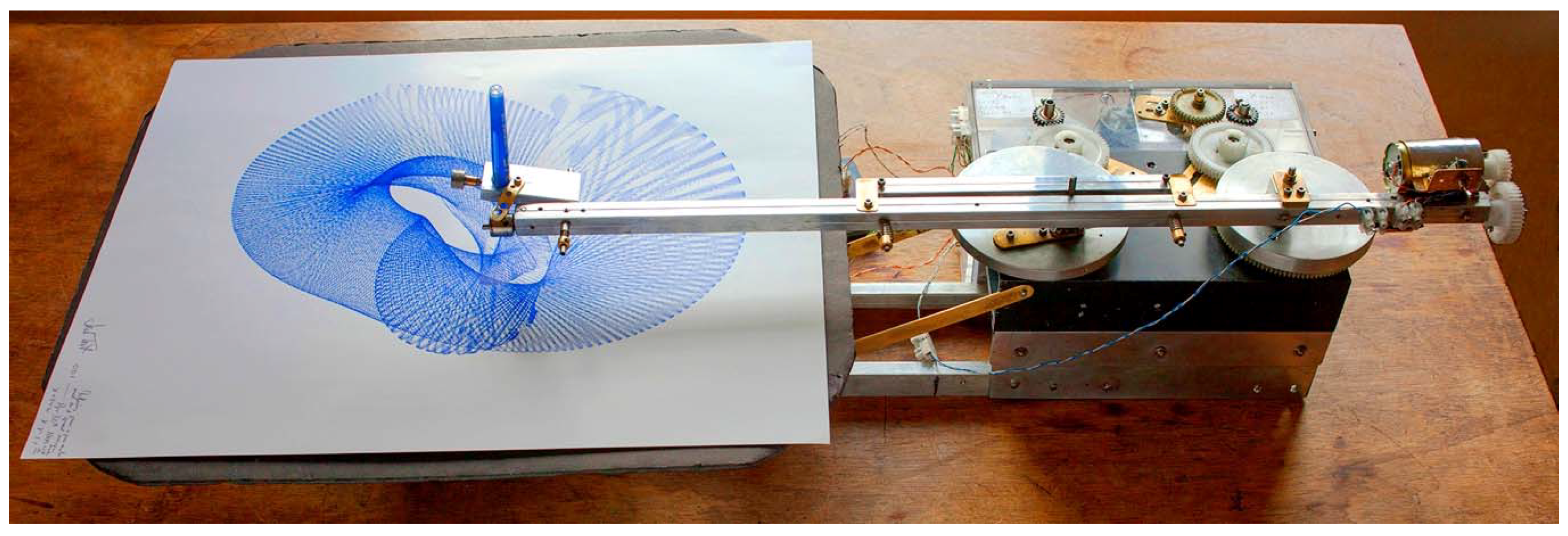
The first machine chosen is the HHM machine,
Figure 2, a precision drawing rig using two axes, X and Y; the X employing a sun and planet drive. The sun and planet drive,
Figure 3, has been found to generate a very rich set of curves and has featured in a number of my devices. The relationship of the X:Y axes is subject to a slow phase change, governed by a main direct current motor driving a differential gear box,
Figure 3, (similar to that on a car’s drive train), whose ‘wheel’ outputs drive the X and Y axes, respectively.
The very slow input to the ‘crown wheel’ portion of the differential is driven by a ‘slave’ direct current motor, geared down so that the X:Y ratio is in the region of 1:1.001. Using a differential means that the phase change ratio can be set to whatever accuracy is required by the programming.
In the HHM machine, the speed of the Y axis (from the differential) is cross coupled to the central ‘sun’ drive of the X axis sun and planet drive whilst the other ‘planet’ part runs at the X speed. This means that the X drive gets out of phase with the Y and the amplitude of the sun and planet crank output varies at the same rate (this variation of the crank amplitude is an inherent characteristic of a sun and planet drive used in this particular way).
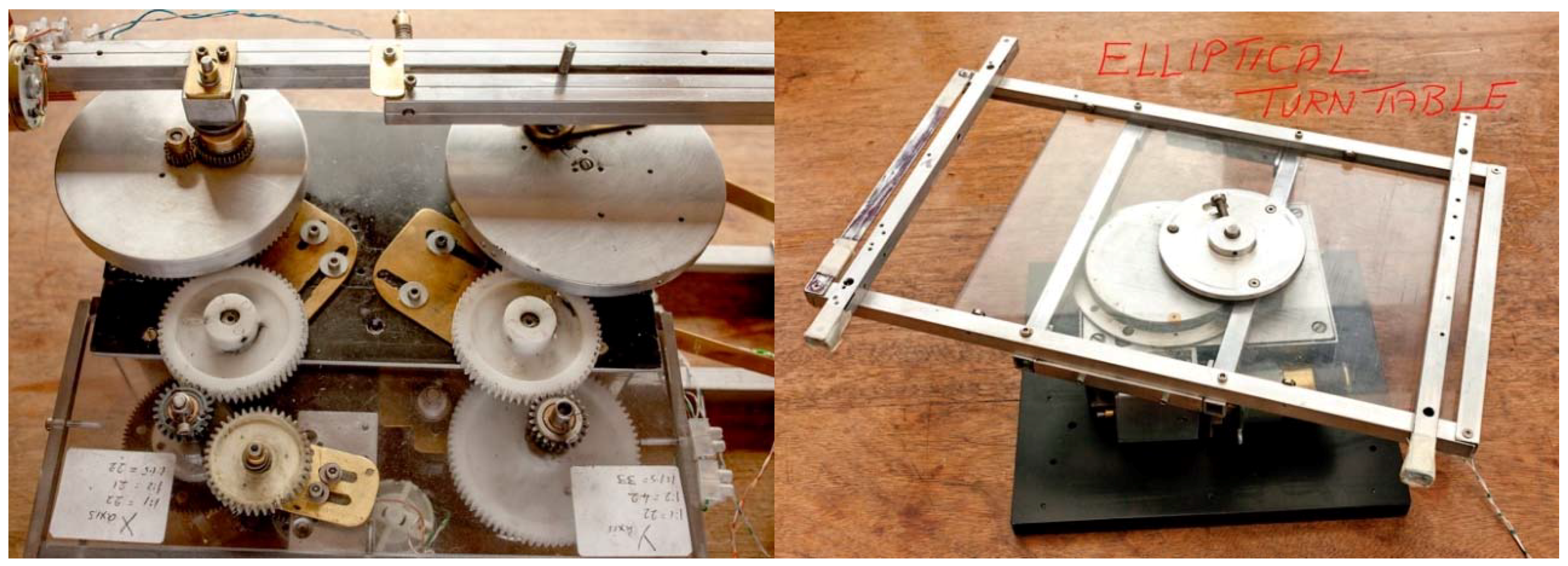
This simple arrangement generates complex drawing outputs, particularly when coupled with an asynchronous pen-lift device run by a third direct current motor. The HHM machine has an elliptical platen instead of a circular one (similar to an elliptical wood turning lathe).
Figure 4. The drive slowly turns the drawing where the turntable to X axis operates in ratios of 1:1200 to 1:2400.
HHM stands for ‘Hommage to Henry.’ Paul Desmond Henry [
13] was an early generative artist working in Manchester in the 70s using a WW2 ‘Sperry’ bombsight computer as his drawing machine. His work, widely celebrated, is in the Victoria and Albert museum London. He left no plans as to how his machine worked, so with the approval of his daughter, Elaine O’Hanrahan, a machine was reverse engineered to mimic his drawings. By analysing the Sperry Bombsight Computer, it proved possible to calculate how the drawings were produced and the first attempt worked well.
This set the author’s research off on a new path, enhancing the first machine by adding precision and modifications. Paul Desmond was not concerned with precision, and was happy to accept the serendipity of the bombsight computer’s output. The additions made were an elliptical turntable, sun and planet X drive, and a pen-lift device. This current machine is used in conjunction with the New TT machine. Note: as the paper was going to press the machine has been modified and is being tested.
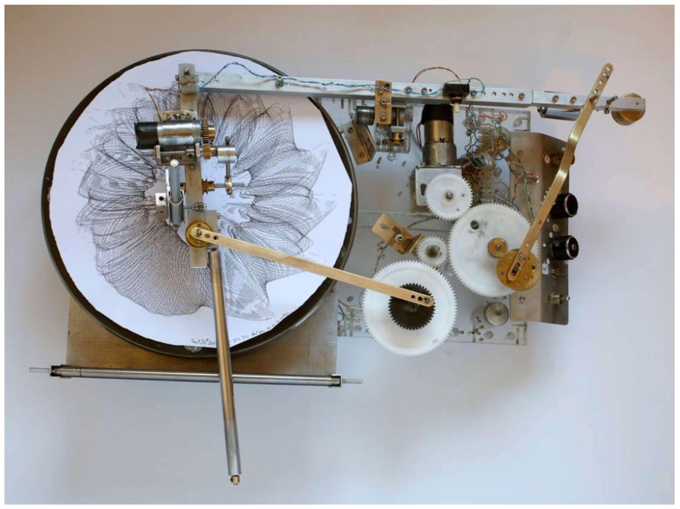
6. NTT Machine Workings
This second machine was developed specifically for this paper in pursuit of chaotic patterns. A turntable based device with linkages; the cartesian coordinates, X and Y, combine with an asynchronous pen-lift action, all operated by number of D.C. motors. It complements facilities of the HHM; one has a differential X:Y relationship, the other uses separate motors operating a sun and planet drive. The two combined significantly increase the range of images.
The latest modification to the NTT is the addition of a ‘static sun/variable planet’ drive (*not shown in the picture
Figure 5; as the machine has different settings). This can be adjusted to act as a sun and planet drive (a static sun still works, as the planet, bearing the crank pin, revolves round the sun). Alternatively, the sun and planet can be set to act as a variable amplitude crank. This addition increases the variables and extends the potential of the machine to explore chaotic states.
There are two parts to the X axis, X1 in a ratio of 1:2 with X2, as part of a sun and planet drive,
Figure 6. The X1:X2 relationship is subject to a phase change with a progression of approximately 1:1.001, allowing a slow organic growth of the drawing. The separate motors are trimmed with a potentiometer used as a simple resistor and they take a long time to get out of phase. In this case, the rate is adjustable.
Other resistors,
Figure 6, control the turntable and pen-lift speeds. The X:Y relationship is either fixed at set ratios of 1:1, 1:2 and 2:3, thus creating the basic Lyssajous figure, or it can have its own ‘static sun/variable planet’ drive switched in (see note* above relating to
Figure 5).
The pen-lift action on both machines increases the richness of the output; it is not intended to synchronise with the X and Y movements. In the NTT (New Turntable Machine), both the configuration of the swing arm linkages and the amplitude of the X and Y cranks contribute to the shape and size of the Lyssajous figures and also affects the way in which the pen-lift enhances the drawing. The machine photographs show the differences.
7. Images Discussed
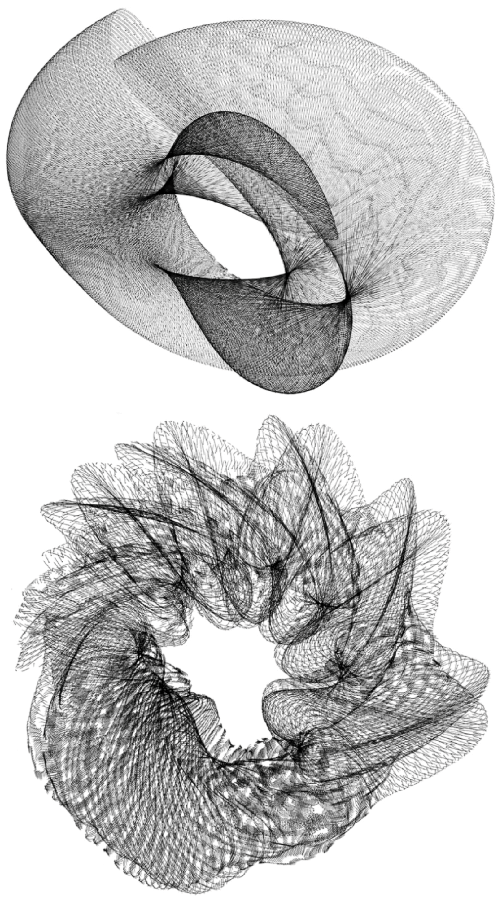
In order to see the development of the images, which ultimately display secondary chaotic patterns, it helps to examine the original drawing without the pen-lift effect, where the differences will be apparent. One from each machine is seen below.
In the HHM image,
Figure 7, the slight inconsistencies in line to line alignment can form a basis on which the pen-lift will work. Whilst the two images have no secondary effects from a pen lift, the NTT machine in particular, as shown in
Figure 8, exhibits some secondary interference patterns. In both cases this amplifies the near chaos character when a pen-lift is employed.
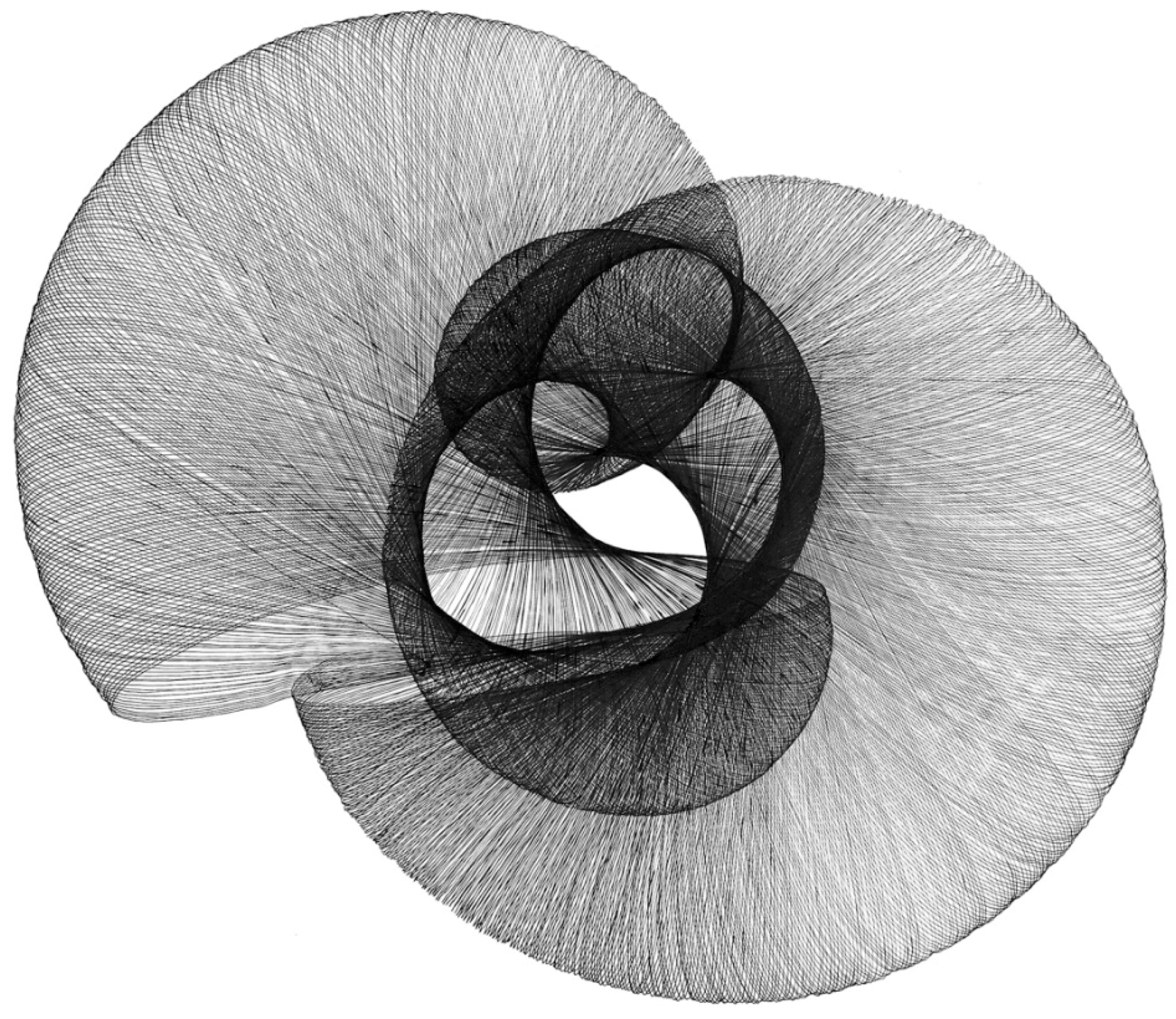
Figure 9, shows a typical HHM drawing, displaying variation in secondary patterns. The pen-lift speed varies in relation to the X:Y speeds owing to the characteristics of the crank rotation. The accuracy and precision of the line to line consistency is crucial to the emergence of the secondary patterns. When the pen-lift is added, secondary patterns emerge; two examples are shown below. In the NTT image
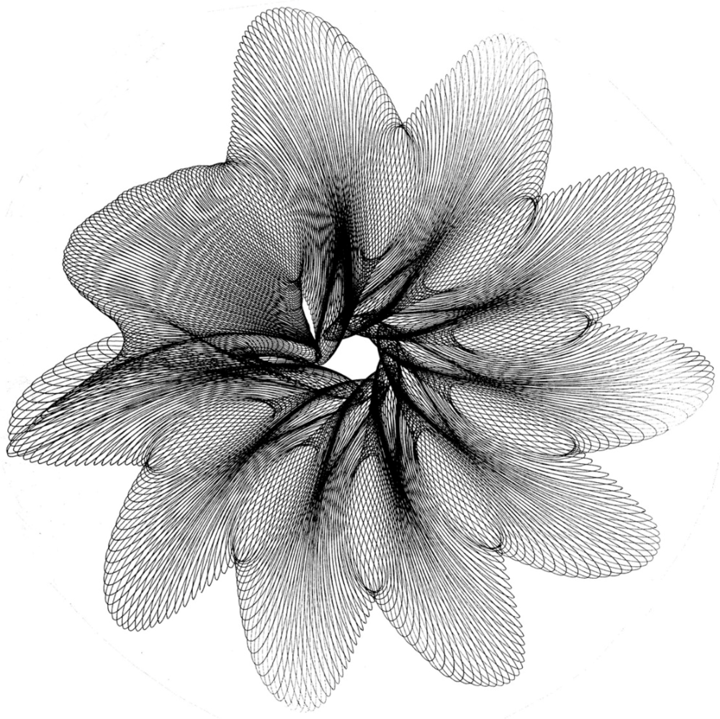
Figure 10, the pen-lift action has shifted its character towards a more chaotic pattern.
Their character can be seen to vary. On the lower right, the lines are close; in the top centre, they open out, taking a sinusoidal form, whilst on the left side, the pattern closes up again. These shifts are due in this machine to the slight variations in phase between the X and Y drives and the pen-lift motor. This phenomenon differs with the NTT machine, where the variations are caused by the two motors driving the X1/X2 sun and planet mechanism to ‘hunt’ under differing load conditions.
The NTT drawing below,
Figure 10, displays characteristics achieving the near chaotic state, which was the purpose of the machine’s design. Given the facilities offered by the NTT and the HHM, it is hoped in the future that drawings can be made to push the boundaries up to the point where graphic coherence has been lost. See
Section 8.
The areas where further research may go is
A—to add a multiple pen device using different colours, and
B—to attempt to overlay two drawings in different colours assuming that the starting parameters can be set with sufficient accuracy. This latter action is extremely demanding as Turing [
1] pointed out. The NTT machine is so current that the above research has not been possible at the time of writing. Development of both machines is ongoing (see Pg 13).
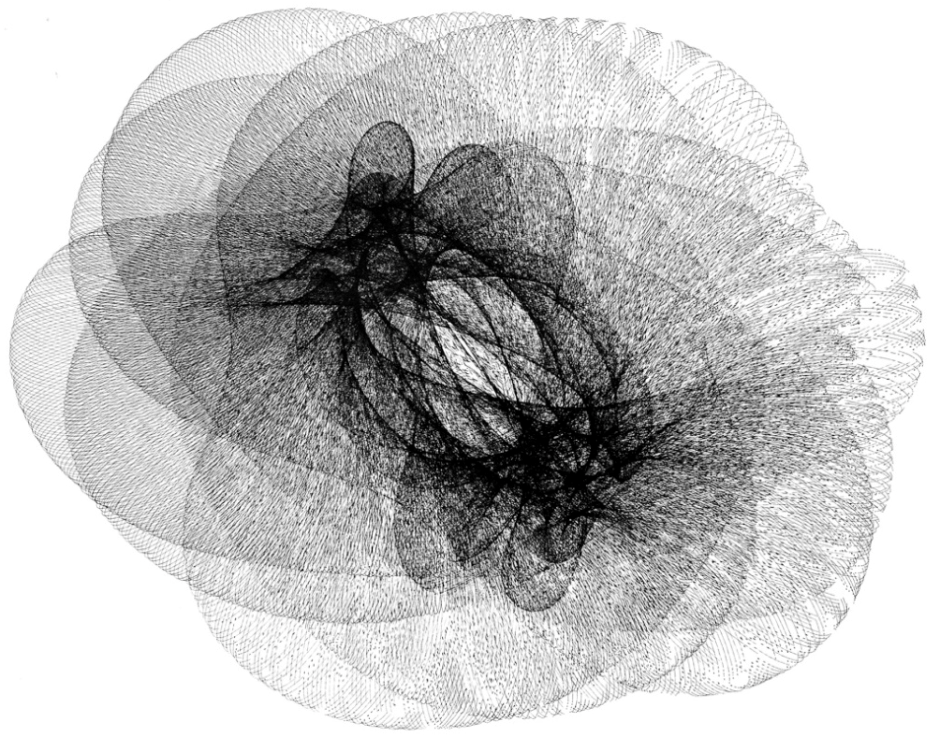
The above drawing from the HHM machine,
Figure 11, was set to the same X:Y configuration, X = 1, Y = 1.5, as the NTT in the preceding page,
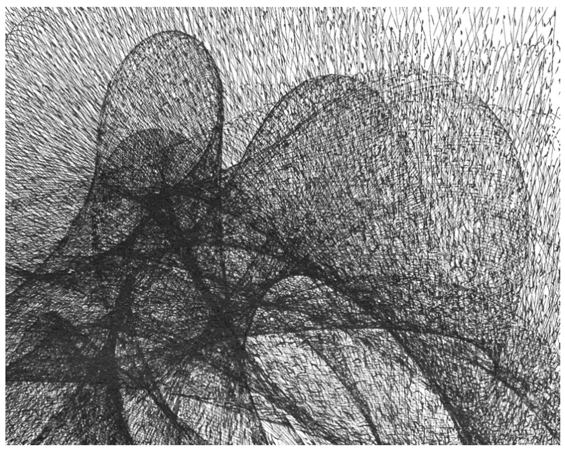
Figure 10. The complexity was increased, but there was a fault in the setting (the turntable was not quite level). It is retained as an exemplar as it shows the difference in character between the no pen-lift on the left to full pen-lift on the right. The detail in the centre approaches chaos (see close up),
Figure 12, although repeated Lyssajeus figures are still evident. It is interesting to note the variation in the character of the secondary patterns in different parts of the drawing. These are a consequence of the accuracy of the line to line control. Without this precision, there would be less coherence; the lines would tend to produce a fully chaotic state.
8. Conclusions
The purpose of the machines is to make art objects. Being machines, they are capable of a large number of outputs and it is only possible to show a minute fraction of the drawings produced. In the text above, their workings were detailed and images were discussed. The common factor was the emergence of secondary patterns facilitated by an asynchronous pen-lift action, where the pattern varied with the pen-lift speed.
Figure 13. Variation extends the exploration of what I call the region of ‘near chaos’ in graphic terms.
From extensive internet searches, it appears that most builders of drawing machines do not investigate the graphic richness of both close line to line effects enhanced by the broken lines resulting from pen-lift actions. This is the reason for the proposal of C above supported by the historical review.
The effects are interesting from a mathematical and scientific perspective, but their chief value to the author is seen to be in their expressive nature,
Figure 14. Research has been motivated by curiosity concerning simple instructions generating complex outcomes. The secondary patterns are the latest manifestation of an interest in near chaos and encourage further research (see Pg 10 last paragraph). It is hoped that curiosity with this aspect of the art process has been shared in the paper.


