Singularity Penetration with Unit Delay (SPUD)


1
Department of Mechanical Engineering, Stanford University, Stanford, CA 94305, USA
2
Department of Mechanical & Aerospace Engineering, Naval Postgraduate School, Monterey, CA 93943, USA
*
Author to whom correspondence should be addressed.
Mathematics 2018, 6(2), 23; https://doi.org/10.3390/math6020023
Submission received: 8 January 2018
/
Revised: 1 February 2018
/
Accepted: 1 February 2018
/
Published: 11 February 2018
(This article belongs to the Special Issue Mathematics on Automation Control Systems)
Abstract
:This manuscript reveals both the full experimental and methodical details of a most-recent patent that demonstrates a much-desired goal of rotational maneuvers via angular exchange momentum, namely extremely high torque without mathematical singularity and accompanying loss of attitude control while the angular momentum trajectory resides in the mathematical singularity. The paper briefly reviews the most recent literature, and then gives theoretical development for implementing the new control methods described in the patent to compute a non-singular steering command to the angular momentum actuators. The theoretical developments are followed by computer simulations used to verify the theoretical computation methodology, and then laboratory experiments are used for validation on a free-floating hardware simulator. A typical 3/4 CMG array skewed at 54.73° yields 0.15H. Utilizing the proposed singularity penetration techniques, 3H momentum is achieved about yaw, 2H about roll, and 1H about pitch representing performance increases of 1900%, 1233%, and 566% respectfully.
1. Introduction
Single gimballed control moment gyroscopes spin a rotating disc at a constant rate, and then by sending a very small voltage signal to the gimbal, the fixed angular momentum vector is rotated, thus changing the direction component of the vector. In accordance with Euler’s rotation equations, any change in angular momentum results in a coupled-nonlinear change in angular momentum as measured in a non-inertial reference frame. The small voltage sent to the gimbal motor produces a large change in angular momentum (equivalently torque), making the control moment gyroscope a highly desirable device for rotational maneuvers. Unfortunately mathematical singularities exist that prevent torque generation in singular directions. Previous research has minimized the mathematical singularity resulting optimal, singularity-free geometries. Next decoupling control methods to reduce the remaining singularities were discovered, leading to the question, “what can be done about the residual mathematical singularities?”. This manuscript answers this question with a newly patented invention that is analytically developed using a thorough review of the previous discoveries, followed by verification via computer simulation and even experimental validation on a free-floating spacecraft simulator. The newly invented singularity penetration is experimentally proven to fly through singularities even without singularity reduction achieved via decoupled control.
This manuscript gives detailed description of the invention in the recently award U.S. Patent, but repeats significant details of the background developments from the literature to permit readers to fully understand the novel development without the need to thoroughly evaluate the literature.
The 3/4 skewed pyramid is studied for rapid rotational maneuvers. Following a description of the analytical setup, Section 2.2 optimization analysis of the skew angle reveals β = 90° produces spherical, singularity-free momentum capability: bidirectional +2H singularity in roll and yaw with +1H singularity free momentum capability in pitch. The analytical description is augmented by a heuristic description that show how singular surfaces collapse into structures that slightly resemble a doughnut with a ring in the middle of the angular momentum space. This optimal singularity-free geometry is established as the baseline geometry. Next, elimination and/or further reduction of the remaining depicted singularities is illustrated utilizing a novel decoupled control methodology that uncouples the system equations from the state-variable formulation that prevents one singular condition from generating three singular steering commands. These configurations are verified in simulation and experimentally validated with hardware experiments. By concentrating on the inner singular surface in the momentum space, a newly patented method is introduced to penetrate this wall of singularity, opening the entire momentum space for rapid rotational maneuvers, free of loss-of-control associated with singularity passage. A typical 3/4 CMG array skewed at 54.73° yields 0.15H. This skew angle is ubiquitously utilized in the literature due to it optimal outer singularity surface. Using the new paradigm and concentrating on the inner singularity surfaces implies increasing the skew angle to ninety degrees and then utilizing the proposed singularity penetration technique, 3H momentum is achieved about yaw, 2H about roll, and 1H about pitch representing performance increases of 1900%, 1233%, and 566% respectfully.
Literature Review
Research began in the 1960s regardless of inability to penetrate singularities in large satellites like SKYLAB. Matrices could not be inverted real-time by automated systems of the day, therefore methodologies that did not necessitate matrix inversion were preferred nearly exclusively with model reduction techniques and other methods to simplify the complicated, coupled and nonlinear equations throughout 1970s and 1980s [1,2,3,4,5].
Gradient methods was frequently used to avoid singularities [3,5], but were more relevantly applied to control moment gyroscopes with two gimbals (and thus two degrees of freedom each), where the extra degree(s) of freedom facilitate the gradient schemes. The first geometric articulation of singularity surface theories was introduced in [6], introducing null motion, and it’s use for singularity avoidance as it applies to control moment gyroscopes with merely one gimbal (and hence no extra degree of freedom to exploit such novelties as gradient schemes). The shapes of singularity surfaces and thus the size of the maneuverable momentum space were introduced in [7] which also described the impacts of gimbal limits. The Russian MIR space station was designed and operated with six single gimbaled control moment gyroscopes, following the declaration in [8] that no less than six gyroscopes yield a momentum space sufficient free of singularities, so as to be useful for attitude control. An important operational consideration has been maintained since that time until today, namely that operators strictly maneuver at angular speeds that keep the momentum trajectory below the threshold established by the first encountered singularity to insure safe operation.
Subsequent research emphasized innovations that permitted a minimally-redundant array of four control moment gyroscopes, where the minimal redundancy is utilized (as the only extra degree of freedom) by the innovative scheme expressed in the research novelty. Treating singularity passage locally (as was the case with the gradient methods) was particularly problematic [7,9,10], as was global optimization attempts via computer simulation [11,12]. Other researchers used the extra degree of freedom of the four gyroscope configuration to invoke novelties of the inversion of the Jacobian matrix of gimbal angles. Other researchers [13,14] sought to add various components to matrix elements to prevent the loss of matrix rank, but that necessitates schemes to minimize the errors induced (since the exact matrix inverse is not calculated, resulting necessarily in slightly incorrect, yet non-singular steering commands). By comparing six such novel steering laws, [15] determined that exact matrix invers determination was required.
Path Planning is another approach used to attempt to avoid singularities that can also achieve optimization if you have knowledge of the command sequence in the near future [6,16,17]. Another method used to avoid singularities is to use null motion to first reorient the CMGs to desired gimbal positions that are not near singular configurations [18]. Despite the massive amount of research done on CMGs, precision control w/CMGs is still an unsolved problem [16,17,19] and is the focus of considerable recent research.
Mathematical formulation of the problem of controlling rotational angular momentum for attitude maneuvers begins with techniques that utilize the underlying physics to inspire control designs, and these designs require math models of the system, sensors, and actuators [20,21]. Astrom and Wittenmark described such designs in their textbook on adaptive control [22]. Slotine [23,24] reveals adaptive control techniques that utilize system math models in their adaptive strategies. Fossen [25] subsequently improved Slotine’s technique with mathematical simplifying problem formulation, and Sands [26,27,28,29,30,31] and Kim [32] developed further improvements to the algorithm based on Fossen’s problem formulation followed by Nakatani [33,34,35] and Heidlauf-Cooper [36,37], but alas these improvements were not revealed in time for publication in Slotine’s text. Particularly relevant to the actuator models, Wie [38] elaborated singularities that exists in the control actuators that can exacerbate or defeat the control design as articulated [39,40,41,42] and solved by Agrawal [43]. Lastly, Sands [20,21,44,45] illustrated ground experimental procedures and on-orbit algorithms for system identification of system math models, while this research article illustrates analytical research of actuator singularities, followed by validation via simulations, and verification using ground experiments.
2. Materials and Methods
Control moment gyroscopes are momentum exchange devices. Commands are sent to the CMG to change its momentum resulting in an equal and opposite change in angular momentum to maintain system equilibrium. Commanded changes in angular momentum are achieved by commanding the gimbal motor to change the direction of the fixed-magnitude angular momentum vector. The Newton-Euler equations (also referred to in the literature as Euler’s moment equations) described the rate of change of angular momentum, resulting in the mathematical relationship between gimbal commands and torque output called a CMG steering law. The 3 steering law equations required for for 3-axis control are combined in matrix form, implying that any one single CMG entering a singularity results in rank-deficient inversion of the matrix expression of the 3 individual equations.
Equations (1)–(4) (substantially repeated in the literature [26,39,40,41,42] leading to the patent [43]) derive this relationship for i = n CMGs normalized by one CMG’s worth of momentum (1H). CMGs are inclined such that their gimbal planes form skew angles, βi with respect to the xy plane (φθ plane). The [A] matrix (containing gimbal angles, δi and skew angles, βi) must be inverted to find the required CMG gimbal command δ for commanded output torque per Equation (4). Begin by writing equations for each momentum vector in xyz (φθψ) coordinates for 3 CMGs normalized by 1H, one CMG’s worth of momentum.
The Newton-Euler relation relates generated torque to the timed-rate of change of angular momentum of the spacecraft system. A CMG absorbs momentum change, causing an equal and opposite change in momentum on the rotating system, where no distinction is made by and . For n CMGs, the general relation is:
For some combinations of gimbal & skew angles, the [A] matrix columns can become linearly dependent. At these combinations of skew and gimbal angles, the determinant of the [A] matrix becomes zero leading to singular inversion.
2.1. The 3/4 Skewed CMG Array
The new paradigm starts by using a modification of the ubiquitous minimally redundant, four-SMG configuration, instead utilizing a non-redundant three-CMG skewed pyramid [24]. Only three actuators are required for 3-axis control, while a fourth is usually used in the literature to provide an extra degree of freedom permitting researchers to investigate singularity avoidance schemes utilizing the extra degree of freedom. Since only three actuators are used here to control angular momentum the fourth actuator may be held in dormant reserve in the event of individual actuator failure. All sections of this manuscript utilize this three-actuator configuration with a balance mass placed in the location of the fourth actuator in the same geometry used in the 4 actuator-configurations. An oft used approach to CMG singularity avoidance is to modify the [A] matrix itself so that it can be inverted during singular conditions, usually by adding various components to the portions of the denominators that are zero (causing the singularity in the first place). A skew angle of at 54.73° comes from optimizing the outer singularity surface, while it is asserted here that a different angle would result by optimizing the inner singularities instead. The next section reveals the optimal (internal) singularity-free skew angle. The rigorous mathematical analysis is immediately followed by a heuristic demonstration that provides significant situational awareness of the momentum space.
2.2. Optimal Singularity-Free Skew Angle
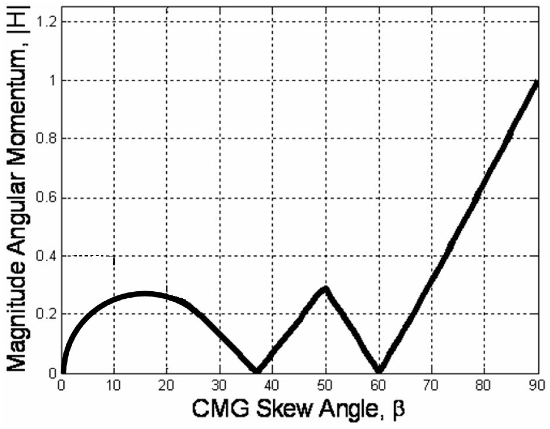
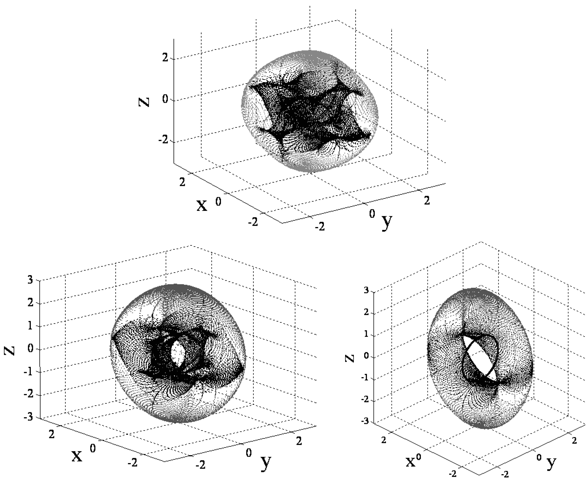
Consider the six cases listed that permit the determinant of the [A] matrix to be zero. Retaining the skew angle as a iterated variable, loop through gimbal angles until a gimbal angle combination meets the criteria for det[A] = 0. For gimbal combinations that meet the criteria, calculate the angular momentum components in each of the three axes and resultant angular momentum magnitude. After iterating for all gimbal combinations at a certain skew angle, the minimum magnitude of angular momentum at a singular condition is the first place a momentum trajectory hits a singularity when departing the origin. This analysis was performed [25] resulting in the optimal singularity-free skew angle of ninety degrees (Figure 1). At this skew angle, the largest momentum space is available for singularity-free torque generation. This is clearly visible in the heuristic plot of singular surfaces for iterated skew angle (Figure 2).
2.3. Mixed Skew Angles
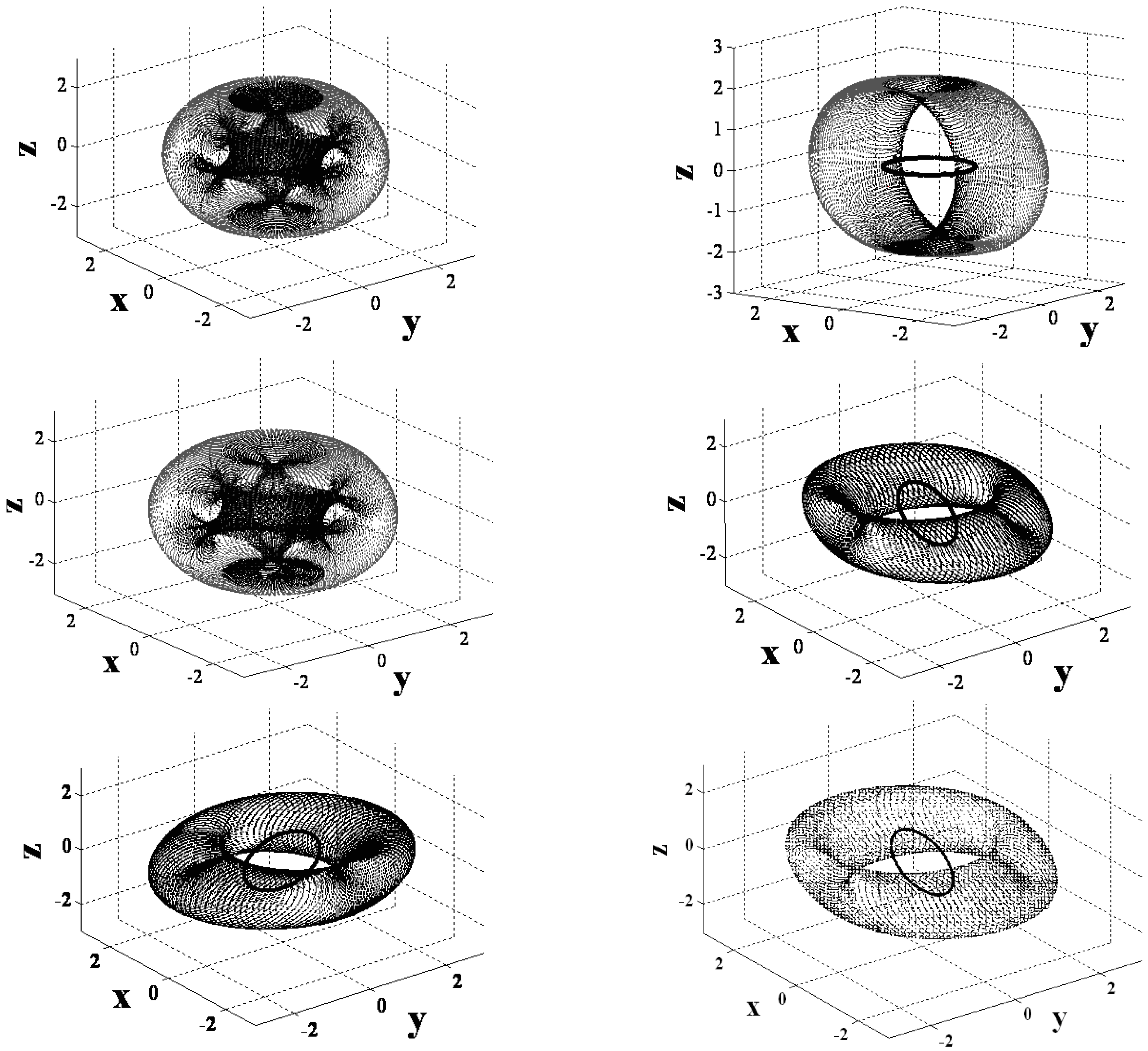
Actuators are normally mounted at the same angle: . By instead mounting the actuators in disparate configurations (e.g., mixed skew angles) , the orientation of the inner region of singularity-free space can be rotated to emphasize a certain maneuver direction (e.g., the yaw direction, which is of primary interest in this study). By rotating momentum planes from ninety degrees to zero degrees, 6 possible reorientations are achieved as listed in Figure 3 and depicted in Figure 4 respectively in the sequence of Figure 3. Simulation and experimental verification of the optimum singularity-free skew angle and mixed skew angle momentum space rotations may be found in references [39,40,41,42,43], but these developments are repeated here as prerequisite knowledge.
2.4. Decoupled Control Analysis
A novel approach, “decoupled control” can be seen by taking advantage of the simplifications that arise from the optimum singularity free skew angle, β = 90°. Substituting skew angle of β = 90° into the [A] matrix in Equation (4) results in Equations (6)–(8):
Note in Equation (8) that the three equations partially decouple. has become decoupled from and . The second equation completely determines pitch momentum which is drive only by the second actuator. It may be safely extracted from the matrix expression of system and utilized individually eliminating singular gimbal commands for actuators that are not themselves singular.
Consider what happens if the first and third CMGs enter a singular angle combination that satisfies = 0. The second actuator would receive infinite steering commands due to the presence of zero in the denominator of the first and third actuator’s equations. Instead, utilizing decoupled steering commands, the second actuator would instead receive a non-singular command seen in Equation (9):
On the other hand, in the case of , only the second actuator is singular, yet using coupled steering commands would send singular (bad) commands to all three actuators. In instead, decoupled control equations are use, roll & yaw maneuvers could be accomplished without added pitch errors avoiding complete loss of 3-axis attitude control, as verified in simulations in Figure 5.
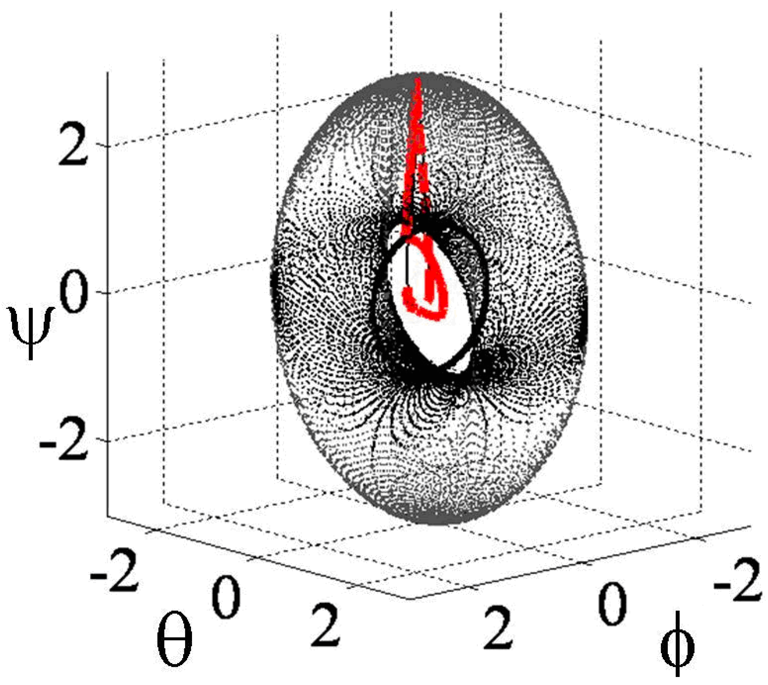
Figure 5 reveals the direct comparison using typical coupled control (thick, red, dashed line) versus decoupled control (thin, black line). When the momentum trajectory encounters the singularity, the coupled control briefly loses attitude control, and eventually recovers afterwards, while the decoupled system penetrates the singularity and traverses the singularity whilst maintaining control authority.
2.5. Singularity Penetration with Unit Delay (SPUD)
The true beauty of SPUD lies in its mathematical expression: where is a gimbal rate value immediately prior to the system becomes singular [44]. The relation’s physical interpretation is described by monitoring the condition of the [A] matrix of gimbal angles using typical methods of linear algebra (e.g., determinant, condition number (inverse) ratio of minimum and maximum singular values, etc.). As a singular condition is approached, the steering logic is engaged, holding the last valid, executable commanded gimbal rate penetrating the singularity and holding that value until the [A] matrix is no longer singular. The scheme has the added benefit traversing the singular condition at a maximal rate, since the singular actuator’s gimbal command is held at its maximal value, yet not permitted to go to infinity (caused by the presence of the zero in the denominator of that actuator’s steering command equation).
3. Results: Verification via Simulation and Validation Experimentally
3.1. Decoupled Control Simulation
Coupled control was established as a baseline for comparison of decoupled control of large-angle angular momentum. A positive fifty degree yaw command is immediately followed by a negative fifty degree command, followed by regulation. Figure 5 displays the direct comparison. The Moore-Penrose pseudoinverse method in the coupled-methodology dramatic roll each time the singularity is encountered, while the decoupled strategy smoothly penetrate the singularity with slight roll or pitch errors in accordance to the descriptive theories developed in Section 2. The second actuator was not singular, and has helped rapidly penetrate and traverse the singularity relying on non-singular actuators that receive commands from the three individual equations comprising the matrix representation in Equation (8). Equation (9) is the individual equation for the second actuator. Thus, both analysis and simulation verify the decoupling technique. Accordingly, experiments were performed on free-floating spacecraft simulator to provide validation in Section 3.3. First, consider now the main contribution of this research, the very recently patented novelty called “SPUD”, singularity penetration with unit delay.
3.2. Singularity Penetration Algorithm
Notice the analysis presented to this point restricts actuators to preferred geometries to facilitate easy decoupling. The following paragraphs will illustrate a technique to penetrate and traverse any singularities (regardless of geometry) without loss of attitude control. When the steering law is sent commands that require inversion of a noninvertible matrix of gimbal angles, loss of attitude control is the result, which can sometimes be quite pronounced. The matrix of gimbal angles is noninvertible when the matrix is “ill conditioned”, i.e., when the maximal & minimal singular values (e.g., from the singular value decomposition) become very widely separated. Equation (5) used the determinant, another method to monitor invertibility of the matrix of gimbal angles. As the matrix becomes more singular, the actuator is getting closer and closer to no-longer being able to produce torque in the commanded direction, resulting in steadily increasing gimbal rate commands (as the denominator moves toward zero and the resulting gimbal command approached theoretical infinity). In actuality, as soon as the commanded gimbal rate meets the maximum possible hardware gimbal rate, the system is “effectively” singular. It is not necessary to wait any longer to initiate the singularity penetration method, where the steering law is augmented to include a unit-delay activated at this critically value essentially holding the final valid gimbal command, penetrating the singularity and traversing the singularity holding this final valid gimbal command until the singularity has passed and the matrix is once again invertible, after which nominal steering is re-activated without the singularity penetration method.
In essence, we are “ignoring” the anomalous, mathematically calculated transient as we pass through the singularity. Henceforth, the technique is referred to as SPUD: singularity penetration w/unit delay.
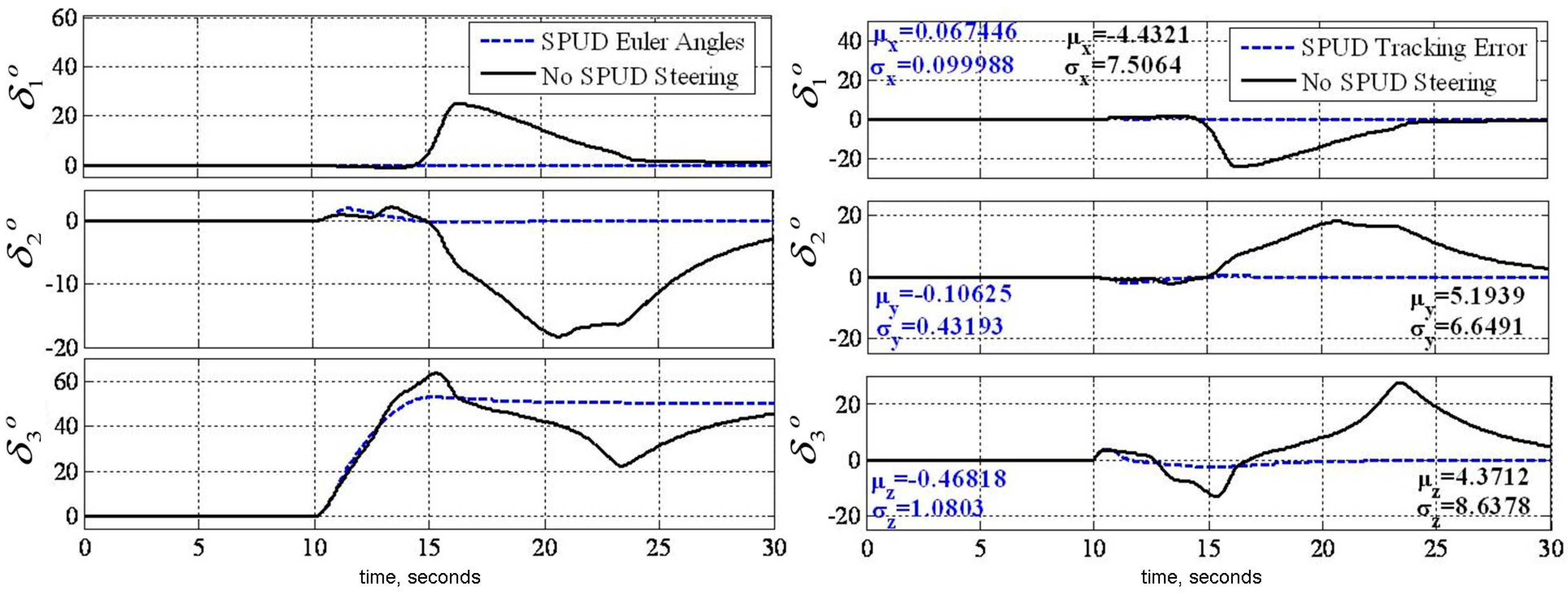
Direct comparisons are again used to reveal the efficacy of the methodology in Figure 6, Figure 7 and Figure 8 depicts. Despite success with decoupled control, the coupled matrix instantiation is used here to isolate that SPUD and SPUD-alone produces the results depicted even without decoupled control, thus SPUD is the most generically effective technique since it applies to other actuator geometries. The left plot in Figure 6 compares Euler angles when commanding a 50° yaw maneuver, while the right plot compares tracking errors for the same maneuver. The solid black line depicts what happened when the momentum trajectory struck a singularity … namely loss of attitude control, followed by eventual recovery after the trajectory was thrown clear of the singularity. The dashed blue line reveal a smooth, uneventful maneuver with smooth gimbal actions, despite penetrating and traversing a singularity.
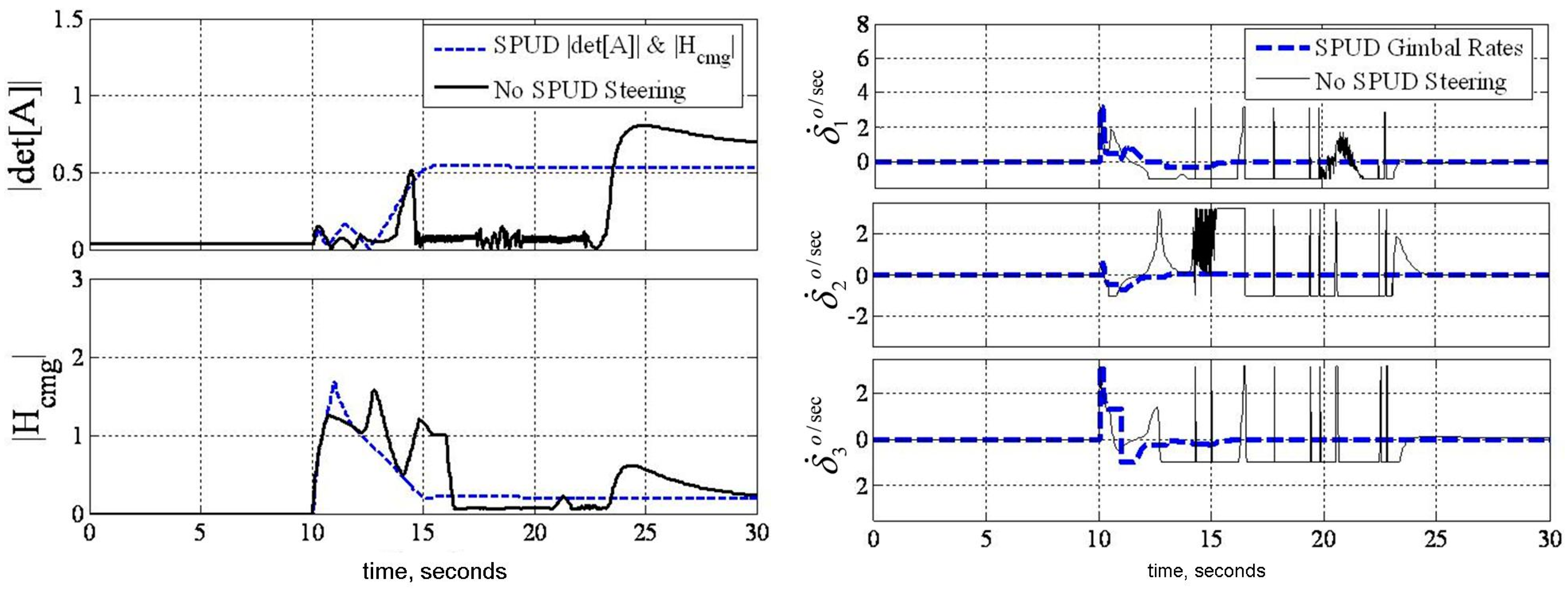
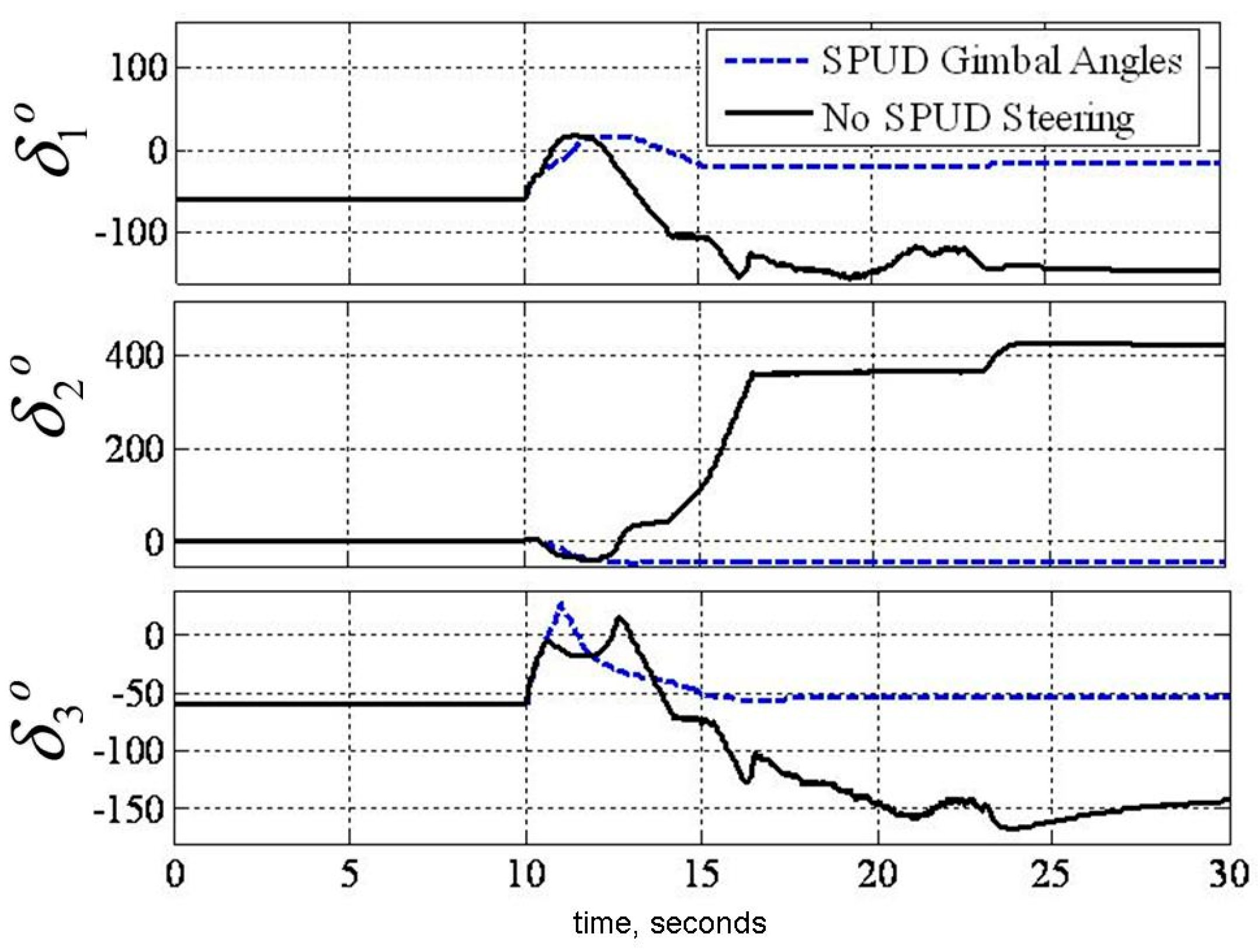
Figure 7 displays key parameters verifying the assertions above. The left plot displays the matrix condition and normalized momentum magnitude for the same maneuver displayed in Figure 6, while the right plot reveals gimbal rates. The magnitude of angular momentum penetrated the singularity at 1H at least four times for the case of No-SPUD before attitude control was re-established, while the SPUD implementation cleanly passed through those singularities (as displayed by the instances where the determinant is zero) while maintaining attitude control. The actuator gimbal commands are pronounced. Without SPUD, the system loses attitude control at the singularity resulting in dramatic back-and-forth commands that saturated the actuators, while with SPUDD, the gimbals moved smoothly with obvious times the gimbals held SPUD commands while traversing the singularity. The gimbal angles themselves are displayed in Figure 8.
3.3. Experimental Verification
3.3.1. Decoupled Control Simulation
Figure 9 displays the experimental results validating decoupled control, where the geometry is the baseline (maximizes yaw momentum space). The left plot reveals penetration and safe traverse of the singularities, yielding the ability to perform a very large angle yaw maneuver displayed in the right plot. The commanded maneuver angle used in the prequel literature [26,40,41,42] was increased 700% from ±5° in 4 s to ±35° in 10 s to show-off the capabilities of decoupled steering. This new yaw maneuver commands significantly higher momentum change. Figure 9 reveals this new enhanced maneuver is achieved without incident despite clearly-evident singularity passage. Recall the coupled [A] matrix would have led to loss of attitude control had decoupled steering not been used.
Typical coupled control steering would have resulted in loss of spacecraft attitude control, and potentially have damaged the actuators (as demonstrated in the simulations depicted in Figure 7). Instead, with decoupled steering, you will notice in Figure 10 a nice maneuver despite singular [A] matrix. Attitude control is not lost at any time. Also notice the extremely high magnitude of normalized momentum (nearly 3H) achieved singularity free. Figure 10 displays the corresponding (very high) momentum magnitude and smooth gimbal actions. The left plot is zoomed to highlight behavior during singularity encounters. Note the maneuver nearly achieved the theoretical maximum value (3H) despite twice traversing singularities with uninterrupted maintenance of control authority.
3.3.2. Decoupled Control Simulation
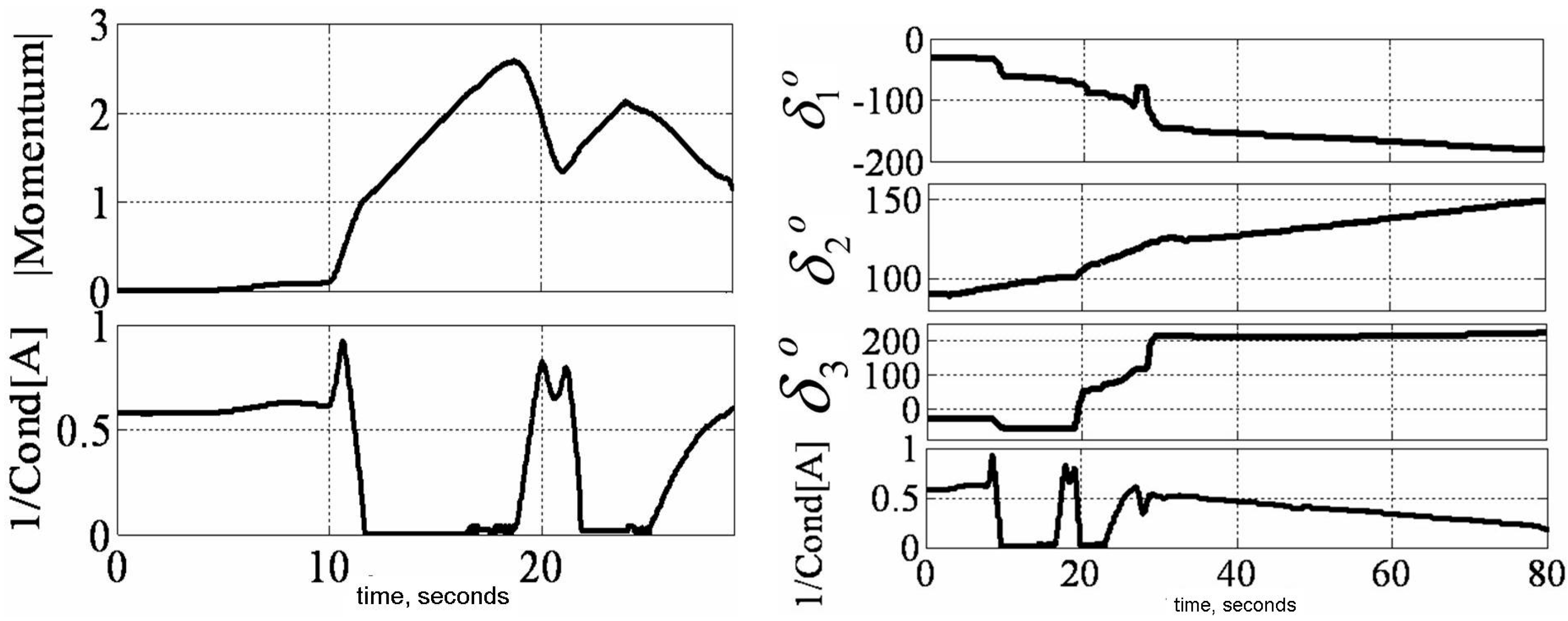
Finally, SPUD-validation was performed using laboratory experiments on the same hardware, this time with direct comparison: SPUD versus No SPUD as displayed in Figure 11.
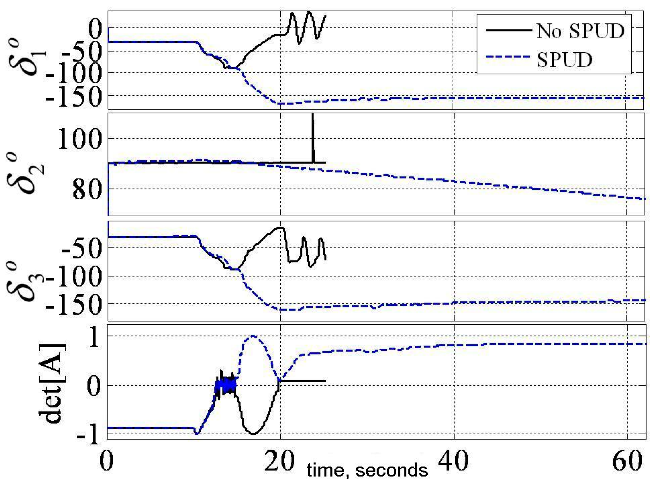
Potential hardware damage associated with loss of control authority when the singularity was encountered without SPUD caused that experiment to be prematurely terminated after about 25 s to prevent financial loss due to hardware damage, while the identical maneuver was performed with SPUD without incident. Roll, pitch, and yaw angles are displayed immediately above the invertibility of the matrix of gimbal angles clearly revealing no loss of control authority despite singularity penetration. This maneuver profiles commanded a thirty degree maneuver in merely eight seconds, immediately followed by a yaw reversal, and then regulation at zero. The maneuver did indeed encounter singularities as evidenced by the right plot of Figure 12 showing both the momentum magnitude and numerical assessment of the invertibility of the [A] matrix. This maneuver in particular was designed to just barely escape the singularity before re-traversing it again in the reverse direction to reveal the insensitivity of SPUD to such challenging trajectories. Smooth actuator gimbal with SPUD is revealed in Figure 13 compared to the loss of attitude control without SPUD.
4. Discussion
This paper tackles a seemingly intractable problem of controlled flight through mathematical singularities. Optimal geometry produces maximized singularity-free momentum space. Further singularity reduction is achieved by decoupling the system equations for the purpose of control steering equations. Finally, singularity penetration and passage is postulated, verified and validated to traverse singularities without loss of control authority. This provides the entire actionable momentum space to the control engineer. These claims are introduced analytically and promising simulations are provided. Finally experimental verification is performed demonstrating dramatic yaw maneuvers that pass through singular surfaces that would render loss of attitude control using typical coupled control techniques. A typical 3/4 CMG array skewed at 54.73° yields 0.15H. Increasing skew angle to ninety degrees and utilizing the proposed singularity penetration technique, 3H momentum is achieved about yaw, 2H about roll, and 1H about pitch representing performance increases of 1900%, 1233%, and 566% respectfully. Such performance increases permit consideration of demanding missions in space [46], and since publication of the patent have become a benchmark for air force education efforts [47] as part of the response [48] to the increasing contestation of American superiority in space [49] in particular as it applied to strategic deterrence [50].
5. Patents
Agrawal, B.; Kim, J.; Sands, T. Method and Apparatus for Singularity Avoidance for Control Moment Gyroscope (CMG) Systems without Using Null Motion. U.S. Patent 9567112 B1, 14 February 2017.
Author Contributions
Sands, Kim, and Agrawal conceived and designed the experiments; Sands performed the experiments; Sands, Kim, and Agrawal analyzed the data; Kim contributed code and analysis tools; Sands wrote the paper. Authorship has been limited to those who have contributed substantially to the work reported.
Conflicts of Interest
The author declares no conflict of interest.
References
- Liska, D.J.; Dean, J. Control moment gyros. In Proceedings of the AIAA Second Annual, San Francisco, CA, USA, 26–29 July 1965; pp. 65–405. [Google Scholar]
- Elrod, B.D.; Anderson, G.M. Equilibrium Properties of the Skylab CMG Rotation Law-Case 620; NASA-CR-126140 (Bellcomm TM-72-1022-2); Bellcomm Inc.: Washington, DC, USA, 1972; p. 79. [Google Scholar]
- Kennel, H.F. Steering Law for Parallel Mounted Double-Gimbaled Control Moment Gyros; NASA-TM-X-64930; NASA Marshall Space Flight Center: Huntsville, AL, USA, 1975; p. 34.
- Colburn, B.K.; White, L.R. Computational considerations for a spacecraft attitude control system employing control moment gyro. J. Spacecr. 1977, 14, 40–42. [Google Scholar] [CrossRef]
- Yoshikawa, T. A Steering Law for Three Double Gimbal Control Moment Gyro System; NASA-TM-X-64926; NASA Marshall Space Flight Center: Huntsville, AL, USA, 1975.
- Magulies, G.; Aubrun, J.N. Geometric theory of single-gimbal control moment gyro system. J. Astronaut. Sci. 1978, 26, 159–191. [Google Scholar]
- Tokar, E.N. Problems of gyroscopic stabilizer control. Cosm. Res. 1978, 15, 141–147, (Original: Kosmicheskie Issledovaniya 1978, 16, 179–187). [Google Scholar]
- Kirokawa, H. A Geometric Study of Single Gimbal Control Moment Gyroscopes; Technical Report of Mechanical Engineering Lab; Mechanical Engineering Lab: Chicago, IL, USA, 7 June 1997; No. 175. [Google Scholar]
- Cornick, D.E. Singularity avoidance control laws for single gimbal control moment gyros. In Proceedings of the AIAA Guidance and Control Conference 79-1968, Boulder, CO, USA, 6–8 August 1979; pp. 20–33. [Google Scholar]
- Kurokawa, H.; Yajima, N.; Usui, S. A CMG attitude control system for balloon use. In Proceedings of the 14th International Symposium on Space Technology and Science (ISTS), Okyo, Japan, 27 May–1 June 1984; pp. 1211–1216. [Google Scholar]
- Kurokawa, H.; Yajima, N.; Usui, S. A New steering law of a single gimbal CMG system of pyramid configuration. In Proceedings of the IFAC Automatic Control in Space, Toulouse, France, 24–28 June 1985; pp. 251–257. [Google Scholar]
- Bauer, S.R. Difficulties encountered in steering single gimbal CMGs. In Space Guidance and Navigation Memo No. 10E-87-09; The Charles Stark Draper Laboratory, Inc.: Cambridge, MA, USA, 1987. [Google Scholar]
- Bedrossian, N.S. Steering Law Design for Redundant Single Gimbal Control Moment Gyro Systems, NASA-CR-172008. Master’s Thesis, Massachusetts Institute of Technology, Cambridge, MA, USA, 1987; p. 138, CSDL-T-965. [Google Scholar]
- Bedrossian, N.S.; Paradiso, J.; Bergmann, E.V.; Rowell, D. Steering law design for redundant single-gimbal control moment gyroscope. AIAA J. Guid. Control Dyn. 1990, 13, 1083–1089. [Google Scholar] [CrossRef]
- National Aeronautics and Space Administration Marshall Space Flight Center (NASA MSFC). A Comparison of CMG Steering Laws for High Energy Astronomy Observatories (HEAOS); NASA TM X-64727; NASA Marshall Space Flight Center: Huntsville, AL, USA, 1972; p. 127.
- Linden, S.P. Precision CMG control for high-accuracy pointing. In Proceedings of the AIAA Guidance and Control Conference, Key Biscayne, FL, USA, 20–22 August 1973; AIAA No. 73-871, p. 7. [Google Scholar]
- Rybak, S.C. Achieving ultrahigh accuracy with a body pointing CMG/RW control system. In Proceedings of the AIAA Guidance and Control Conference, Key Biscayne, FL, USA, 20–22 August 1973; AIAA No. 73-871, p. 7. [Google Scholar]
- Vadali, S.R.; Oh, H.S.; Walker, S.R. Preferred gimbal angles for single gimbal control moment gyros. J. Guid. 1990, 13, 1090–1095. [Google Scholar] [CrossRef]
- Seltzer, S.M. CMG-Induced LST Dynamics; NASA-TM-X-64833; NASA Marshall Space Flight Center: Huntsville, AL, USA, 1974; p. 80.
- Sands, T.; Armani, C. Analysis, Correlation, and Estimation for Control of Material Properties. J. Mech. Eng. Autom. 2018, 8, 7–31. [Google Scholar] [CrossRef]
- Sands, T. Experimental Sensor Characterization. J. Space Explor. 2018, 7, 140. [Google Scholar]
- Astrom, K.; Wittenmark, B. Adaptive Control, 2nd ed.; Addison Wesley Longman: Boston, MA, USA, 1995. [Google Scholar]
- Slotine, J.; Benedetto, M. Hamiltonian adaptive control of spacecraft. IEEE Trans. Autom. Control 1990, 35, 848–852. [Google Scholar] [CrossRef]
- Slotine, J.; Li, W. Applied Nonlinear Control; Pearson Publishers: Cambridge, MA, USA, 1990; Chapter 8. [Google Scholar]
- Fossen, T.I. Comments on Hamiltonian adaptive control of spacecraft. IEEE Trans. Autom. Control 1993, 38, 671–672. [Google Scholar] [CrossRef]
- Sands, T. Fine Pointing of Military Spacecraft. Ph.D. Dissertation, Naval Postgraduate School, Monterey, CA, USA, 2007. [Google Scholar]
- Sands, T.; Lorenz, R. Physics-Based Automated Control of Spacecraft. In Proceedings of the AIAA Space 2009 Conference and Exposition, Pasadena, CA, USA, 14–17 September 2009. [Google Scholar]
- Sands, T. Physics-Based Control Methods. In Advancements in Spacecraft Systems and Orbit Determination; In-Tech Publishers: Rijeka, Croatia, 2012; pp. 29–54. [Google Scholar]
- Sands, T. Improved Magnetic Levitation via Online Disturbance Decoupling. Phys. J. 2015, 1, 272–280. [Google Scholar]
- Sands, T. Nonlinear-Adaptive Mathematical System Identification. Computation 2017, 5, 47. [Google Scholar] [CrossRef]
- Sands, T. Phase Lag Elimination at All Frequencies for Full State Estimation of Spacecraft Attitude. Phys. J. 2017, 3, 1–12. [Google Scholar]
- Kim, J.; Sands, T.; Agrawal, B. Acquisition, Tracking, and Pointing Technology Development for Bifocal Relay Mirror Spacecraft. In Proceedings of the Defense and Security Symposium, Orlando, FL, USA, 7 May 2007; Volume 6569. [Google Scholar]
- Nakatani, S.; Sands, T. Autonomous Damage Recovery in Space. Int. J. Autom. Control Intell. Syst. 2016, 2, 23–36. [Google Scholar]
- Nakatani, S.; Sands, T. Simulation of Spacecraft Damage Tolerance and Adaptive Controls. In Proceedings of the IEEE Aerospace Proceedings, Big Sky, MT, USA, 1–8 March 2014. [Google Scholar]
- Nakatani, S.; Sands, T. Battle-damage Tolerant Automatic Controls. Electr. Electron. Eng. 2018, 8, 10–23. [Google Scholar] [CrossRef]
- Heidlauf, P.; Cooper, M. Nonlinear Lyapunov Control Improved by an Extended Least Squares Adaptive Feed forward Controller and Enhanced Luenberger Observer. In Proceedings of the International Conference and Exhibition on Mechanical & Aerospace Engineering, Las Vegas, NV, USA, 2–4 October 2017. [Google Scholar]
- Cooper, M.; Heidlauf, P.; Sands, T. Controlling Chaos—Forced van der Pol Equation. Mathematics 2017, 5, 70. [Google Scholar] [CrossRef]
- Wie, B. Robust Singularity Avoidance in Satellite Attitude Control. U.S. Patent 6039290 A, 21 March 2000. [Google Scholar]
- Sands, T.; Kim, J.; Agrawal, B. 2H Singularity-Free Momentum Generation with Non-Redundant Single Gimbaled Control Moment Gyroscopes. In Proceedings of the 45th IEEE Conference on Decision & Control, San Diego, CA, USA, 13–15 December 2006. [Google Scholar]
- Sands, T. Control Moment Gyroscope Singularity Reduction via Decoupled Control. In Proceedings of the IEEE SEC Proceedings, Atlanta, GA, USA, 5–8 March 2009. [Google Scholar]
- Sands, T.; Kim, J.; Agrawal, B. Nonredundant Single-Gimbaled Control Moment Gyroscopes. J. Guid. Control Dyn. 2012, 35, 578–587. [Google Scholar] [CrossRef] [Green Version]
- Sands, T. Experiments in Control of Rotational Mechanics. Int. J. Autom. Control Intell. Syst. 2016, 2, 9–22. [Google Scholar]
- Agrawal, B.; Kim, J.; Sands, T. Method and Apparatus for Singularity Avoidance for Control Moment Gyroscope (CMG) Systems without Using Null Motion. U.S. Patent 9567112 B1, 14 February 2017. [Google Scholar]
- Sands, T.; Kenny, T. Experimental Piezoelectric System Identification. J. Mech. Eng. Autom. 2017, 7, 179–195. [Google Scholar]
- Sands, T. Space System Identification Algorithms. J. Space Explor. 2018, 6, 138. [Google Scholar]
- Sands, T. Space Mission Analysis and Design for Electromagnetic Suppression of Radar. Int. J. Electromag Apps 2018. submitted. [Google Scholar]
- Mihalik, R.; Camacho, H.; Sands, T. Continuum of Learning: Combining Education, Training, and Experiences. Education 2018, 8, 9–13. [Google Scholar] [CrossRef]
- Sands, T.; Camacho, H.; Mihalik, R. Education in Nuclear Deterrence and Assurance. J. Def. Manag. 2017, 7. [Google Scholar] [CrossRef]
- Sands, T.; Lu, D.; Chu, J.; Cheng, B. Developments in Angular Momentum Exchange. Int. J. Aero. Sci. 2018, 6. submitted. [Google Scholar]
- Mihalik, R.; Camacho, H.; Crook, M.; Sands, T.; Nichols, T. Study on the 2018 Nuclear Posture Review. Soc. Sci. 2018, unpublished manuscript. [Google Scholar]
Figure 1.
ITERATION: Optimum singularity-free CMG skew angle, β.

Figure 2.
Heuristic analysis varying skew angle, β for a 3/4 CMG skewed array. β was varied in 5° increments from 0° to 90° identifying the trend represented here by three primary plots with 3H &0H singular surface lightened to enable visualization of 1H & 2H singular surfaces: β = 70° (top), 80° (lower left), 90° (lower right).

Figure 3.
Six possible combinations of mixed skew angles laying one or two momentum cutting planes from 0° to 90°. Corresponding singular hypersurfaces are depicted in respective order in Figure 4.
Figure 3.
Six possible combinations of mixed skew angles laying one or two momentum cutting planes from 0° to 90°. Corresponding singular hypersurfaces are depicted in respective order in Figure 4.
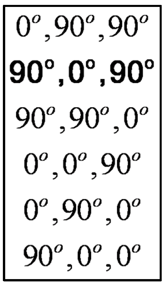
Figure 4.
Singular hypersurfaces resulting from 6 possible combinations of mixed skew angles. Singular surfaces from upper left correspond to sequence of mixed skew angles per Figure 3.
Figure 4.
Singular hypersurfaces resulting from 6 possible combinations of mixed skew angles. Singular surfaces from upper left correspond to sequence of mixed skew angles per Figure 3.

Figure 5.
SIMULATION: Direct comparison of coupled versus decoupled control methods.

Figure 6.
SIMULATION: Verifying the efficacy of SPUD.

Figure 7.
SIMULATION: Empirical data verifying the efficacy of SPUD.
Figure 9.
EXPERIMENTATION: Validating efficacy of decoupled control.

Figure 10.
EXPERIMENTATION: momentum, matrix condition, and gimbal rates.

Figure 11.
EXPERIMENTATION: direct comparison with SPUD versus without SPUD.
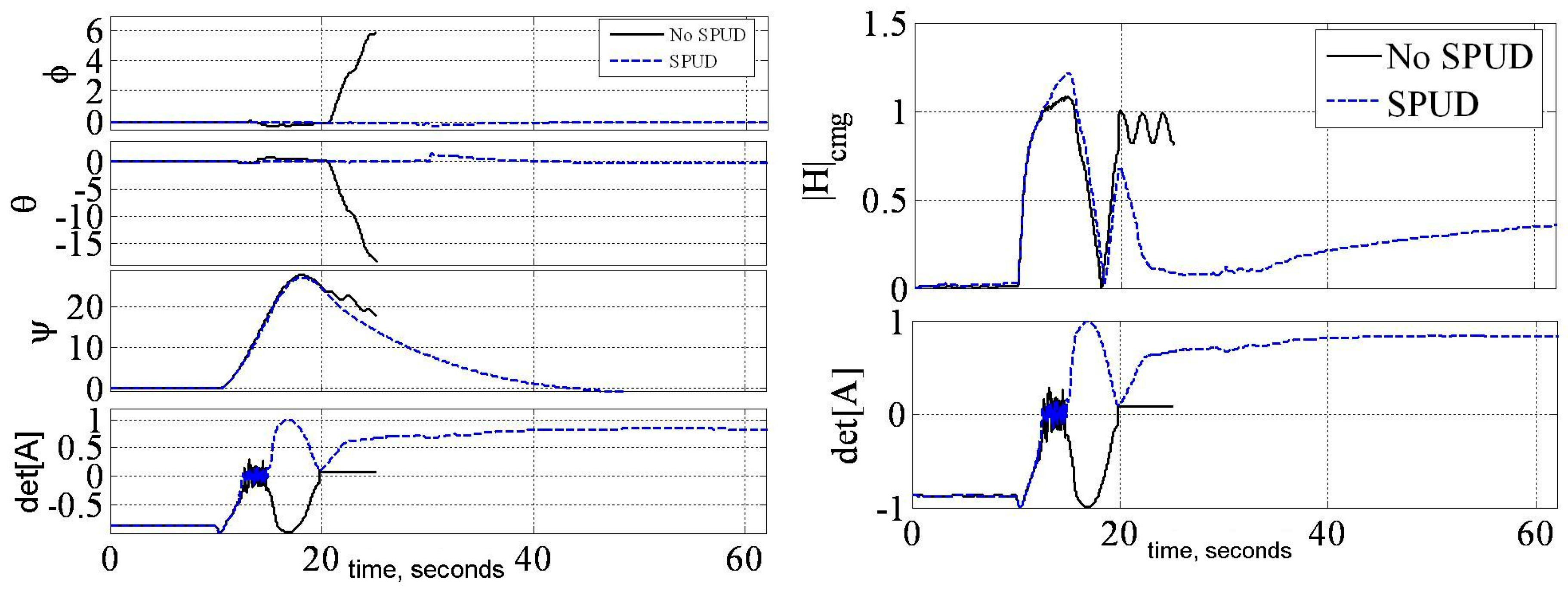
Figure 12.
EXPERIMENTATION: Direct comparison of SPUD to nominal control methods.
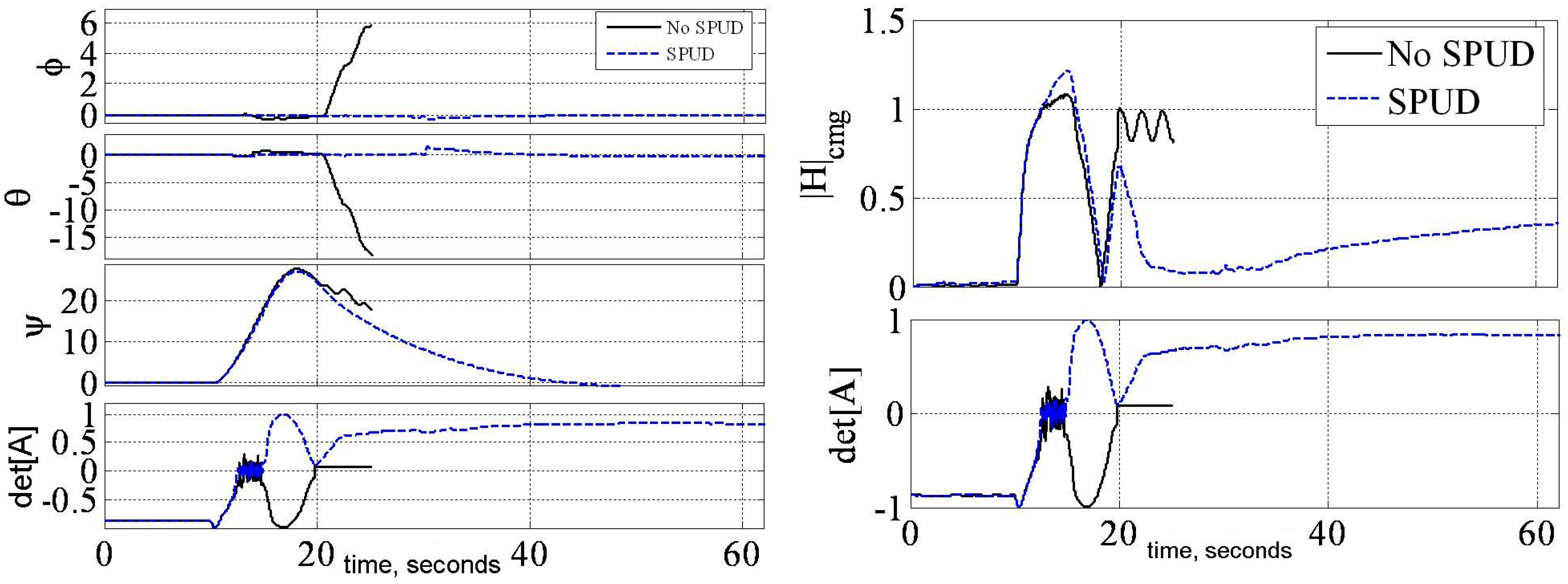
Figure 13.
EXPERIMENTATION: Gimbal angles (top) and det[A] (bottom) versus time (seconds) associated with Figure 12.
Figure 13.
EXPERIMENTATION: Gimbal angles (top) and det[A] (bottom) versus time (seconds) associated with Figure 12.

© 2018 by the authors. Licensee MDPI, Basel, Switzerland. This article is an open access article distributed under the terms and conditions of the Creative Commons Attribution (CC BY) license (http://creativecommons.org/licenses/by/4.0/).
Share and Cite
MDPI and ACS Style
Sands, T.; Kim, J.J.; Agrawal, B. Singularity Penetration with Unit Delay (SPUD). Mathematics 2018, 6, 23. https://doi.org/10.3390/math6020023
AMA Style
Sands T, Kim JJ, Agrawal B. Singularity Penetration with Unit Delay (SPUD). Mathematics. 2018; 6(2):23. https://doi.org/10.3390/math6020023
Chicago/Turabian StyleSands, Timothy, Jae Jun Kim, and Brij Agrawal. 2018. "Singularity Penetration with Unit Delay (SPUD)" Mathematics 6, no. 2: 23. https://doi.org/10.3390/math6020023
Note that from the first issue of 2016, this journal uses article numbers instead of page numbers. See further details here.