
A New Hybrid Synchronization PLL Scheme for Interconnecting Renewable Energy Sources to an Abnormal Electric Grid


1
Department of Electrical Engineering, College of Engineering, University of Ha’il, Ha’il 81451, Saudi Arabia
2
Institute of Applied Sciences and Technology of Kasserine (ISSATKas), University of Kairouan, P.O. Box 471, Kasserine 1200, Tunisia
3
LaTICE Laboratory, Higher National Engineering School of Tunis (ENSIT), University of Tunis, 5 Avenue Taha Hussein, P.O. Box 56, Tunis 1008, Tunisia
4
Department of Industrical Engineering, College of Engineering, University of Ha’il, Ha’il 81451, Saudi Arabia
*
Author to whom correspondence should be addressed.
Mathematics 2022, 10(7), 1101; https://doi.org/10.3390/math10071101
Submission received: 16 February 2022
/
Revised: 23 March 2022
/
Accepted: 26 March 2022
/
Published: 29 March 2022
(This article belongs to the Special Issue Mathematical Methods and Models Applied in Information Technology and Electrical Engineering)
Abstract
:Today, and especially with the growing interest in distributed renewable energy sources (DRESs), modern electric power systems are becoming more and more complex. In order to increase DRES penetration, grid side converter (GSC) control techniques require appropriate synchronization algorithms that are able to detect the grid voltage status as fast and accurately as possible. The drawbacks of the published synchronization phase-locked loop (PLL) techniques were structured mainly around the slow dynamic responses, the inaccuracy of extracting the fundamental components of the grid voltages when they contain a DC offset, and the worsening of the imbalance rejection ability facing significant frequency changing. This paper proposes a new synchronization PLL technique ensuring efficient and reliable integration of DRESs under normal, abnormal, and harmonically distorted grid conditions. The proposed PLL uses the mixed second- and third-order generalized integrator (MSTOGI) in the prefiltering stage through its adaptability to power quality and numerous grid conditions and its low sensitivity to input DC and inter-harmonics. Moreover, a modified quasi type-1 PLL (MQT1-PLL), which integrates two compensation blocks for phase and amplitude errors, respectively, has been used in the control loop. The discussion of sizing requirements and the effectiveness of the so-called MSTOGI-MQT1-PLL are tested under grid voltage imbalances and distortions and confirmed through simulation results compared to double second-order generalized integrator PLL (DSOGI-PLL), cascaded delayed signal cancellation PLL (CDSC-PLL), and multiple delayed-signal cancellation PLL (MDSC-PLL).
1. Introduction
Renewable energy sources (RESs), energy sources that are generally placed close to local loads and which may, in some cases, offer complete power to the local system, have been seen primarily as an energy solution for remote areas or as an emergency alternative energy [1]. Today, these sources of energy are seen not only as an important solution to improve the capacity and energy availability of the planet but also as a means of countering current issues such as climate change and greenhouse gas emissions (GHG) [2,3]. The optimal use of distributed energy resources (DER) requires the integration of these resources with the local network or even the parallelization of decentralized energy sources with those of the network [4,5]. In this context, today’s electric power system is undergoing rapid changes due to the integration of DRESs [6,7,8,9,10,11]. This integration, mainly ensured by the grid side converter (GSC), is limited by significant technical barriers, including the unintentional island mode operation of decentralized generation units following grid imbalance, loss, or disconnection [12,13].
In accordance with modern power system regulations and the growth of the recent control systems [14,15], the GSCs and their control algorithms must be equipped with advanced functionalities to allow them to operate regardless of grid conditions [16,17]. To accomplish this task, the GSC converter control system is split into three main modules: the external control loop module taking care of the regulation of the active/reactive power exchanged, the internal control loop module of the currents, and the synchronization module [18].
The active and reactive power controller performs the generation of the current references, which are then processed by the current controller to generate the required powers [19]. Furthermore, the synchronization module is responsible for instantaneously extracting information relating to the phase angle and frequency of the grid voltage, which are essential for the accurate functioning of control loops [20]. During significant grid disturbances, the GSC converter is found to be incompatible with remaining interconnected, without well-designed control strategies relying upon vigorous synchronization techniques [21]. The phase-locked loop synchronization technique is recognized as an indispensable process for detecting the phase, amplitude, and frequency of the grid voltage in a fast and accurate way [12,22]. This is crucial for the design of a control system capable of enabling the GSC to contribute appropriately to global grid stability, even in the event of the occurrence of disturbances.
This issue is becoming more and more paramount to allow energy sector operators and managers to ensure short- and long-term energy efficiency and the management of bidirectional energy flows between electrical energy production sources and coordinated consumption. The growing interest in distributed power generation systems (DPGSs) based on renewable energy has increased the number of topologies that have appeared for integrating renewable power source-based systems into the electricity grid [23,24]. In applications connected to the power supply network, the interfacing of the electricity production from renewable energy sources to the grid is ensured mainly by a DC-AC converter and a filter attenuating the harmonics of the currents injected at the grid [25,26,27].
It is obvious that the power electronics converters are a key and strategic point for energy production and management [28]. Similar to renewable energy productions, advanced studies in the field of power electronics converters are also growing faster than foreseen [29]. More and more demanding specifications in power electronics dictate that the GSC should have an excess capacity that can be exploited to participate in ancillary services to the main grid [30,31]. These requirements are prescribed by restrictive standards on the quality of the energy produced and distributed (IEEE_1547, 2018), in particular on the harmonics induced by the GSC switching [32]. To achieve these objectives, recent research works have considered two methods, namely the development of new control strategies and the implementation of new structures or topologies of the GSC converter [27,28,31]. However, with a view to developing such converter control strategies, particular attention has been paid to techniques of synchronization with the network. In recent years, these techniques have experienced exponential development [33,34,35]. This development is mainly motivated both by the increase in the rate of integrating RESs into the modern electricity system, its harmful consequences for the stability of the network, and by the increasingly stringent requirements of power quality [36].
In modern electrical networks, the voltage may vary temporarily due to fluctuations in production, load, or a short circuit. Sudden fluctuations cause a voltage dip, the depth and duration of which vary according to the characteristics of the network and the production groups concerned [37]. In particular, the behavior of RES systems in the face of voltage dips and their resistance to disturbances under fault conditions have attracted several studies from around the world [38]. It has been shown that GSC inverters have a high sensitivity to imbalances in the network voltage, which can cause their untimely disconnection. In [39], it has been shown that this sensitivity systematically depends on the types of faults, its position, the protection systems, and especially on the topology of the inverter and its control/command system (e.g., PLL, limit current of its control system).
In recent years, several published works have been suggested and investigated for improvement of the stability of grid-connected voltage source inverters (VSIs) interfacing renewable energy sources [34]. Among the published works, the majority of them emphasize the vital role of grid synchronization in grid-connected VSIs [37,38].
A precise PLL necessarily contributes to the enhancement of the stability of the RES-based systems connected to the network by guaranteeing that the currents injected into the network are in phase with the grid voltages. A PLL can also decrease total harmonic distortion (THD) and significantly advance the quality of the waveform of currents injected into the grid [36,39].
In the literature, several PLLs have been proposed; the main drawbacks of them are related to some issues in power quality such as frequency variations and voltage waveform distortions. Under balanced grid conditions, the synchronous reference frame (SRF) phase-locked loop (SRF-PLL) [40,41] has been a reasonable candidate due to its fast dynamic response, simple structure, and feasible software implementation.
Nevertheless, the SRF-PLL method performance is severely degraded under off-nominal grid voltage conditions. Errors appear in tracking the fundamental component of the positive sequence voltages and disturb the whole control system of the grid-connected inverter.
In order to address the limitations of SRF-PLL when an imbalance and/or harmonics occur at the grid voltages, another method called double-decoupled SRF-PLL (DDSRF-PLL) has been suggested in [42]. Because of the use of a decoupling network, it has been proven that the DDSRF-PLL has succeeded in extracting the components of the positive and negative sequences and eliminating the oscillations that arise during grid voltage disturbances. Along with its benefits to achieve accurate phase-locking, however, the DDSRF-PLL has a rather complicated software implementation and a slow dynamic response due to the integrated low-pass filters [37].
Still, in the enumeration of the efforts of researchers with regard to the techniques of PLLs, another method called SOGI-PLL has been proposed. This method is based on using second-order generalized integrators. It has been shown that SOGI-PLL is simple and efficient even under faulty conditions of the grid voltages since it succeeds in mitigating the delay caused by the low-pass filter introduced by the DDSRF-PLL. Nevertheless, it has been demonstrated that the performance of the third-order generalized integrator-PLL (TOGI-PLL) and the SOGI-PLL technique and its derivatives SSOGI-PLL [43] and DSOGI-PLL [44] deteriorate, especially when a DC offset is present in grid voltages.
To address the last issue, other attempts [45] have tried to exploit the strengths of PI integrators and the Kalman filter to remove the DC offset. In the same context of eliminating the adverse effects of the DC offset on PLL techniques, a cascaded generalized integrator PLL (CGI-PLL) has been recently proposed by N. Hui et al. [21].
Among the options of the PLL pre-filtering step, the delayed signal cancellation (DSC) theory has become popular for extracting the fundamental component of grid voltages that is used by the synchronous reference frame PLL (SRF-PLL) [46]. Several derived approaches, such as the generalized DSC (GDSC), the multiple DSC (MDSC) [47,48], the cascaded (CDSC) and the non-adaptive CDSC (NCDSC), have been used [49]. In particular, the NCDSCs have succeeded in resolving the instabilities that are engendered by the CDSCs. Conversely, the major drawbacks of DSC-based operators are linked to two challenges associated, in turn, to the dynamic response and the rejection of imbalances for large and rapid changes in frequency. Figure 1 classifies the synchronization up-to-date techniques.
Within this context, the present paper investigates the development of a well-designed synchronization technique of grid-tied inverters. On the basis of a bibliographic review of Section 1, a detailed analysis of the TOGI approach from the SOGI perspective is conducted, and the MSTOGI-MQT1-PLL method is suggested in Section 2 and validated through simulations in Section 3. Finally, Section 4 summarizes and concludes the paper.
The foremost contributions of the current paper that propose a new synchronization phase-locked loop for DRESs are summarized as follows:
- The structure of the dual-mixed integrator MSTOGI involves an additional branch whose main advantage is the elimination of the DC offset of the input voltages, which is a weakness of the SOGI and TOGI integrators, without the addition of any new parameter.
- The non-adaptive MSTOGI perfectly performing the pre-filtering task overcomes the sensitivity of the classical filtering techniques to the DC offset of the grid voltage and to harmonics and inter-harmonics.
- The MQT1 technique is suggested to achieve phase locking. This technique was supported by two blocks that are responsible for compensating the amplitude error and the phase shift and correcting them independently of the frequency variation of the grid voltages.
- The coherent structure of the MSTOGI-MQT1-PLL showed promising performances in terms of the speed and accuracy of phase locking by comparing to the well-cited techniques DSOGI-PLL, CDSC-PLL, and MDSC-PLL.
2. Methods and Materials
In this section, knowing that the proposed PLL technique is based on a mixed MSTOGI integrator, the primary focus has analyzed TOGI from the SOGI point of view. Here, the basic principle of the SOGI structure and its limitations have been revealed before presenting the TOGI structure and its ability to eliminate the DC offset. Thereafter this introduction, the MSTOGI-MQT1-PLL structure is described in detail.
2.1. Analysis of TOGI from SOGI Perspective
2.1.1. Basic Principle of SOGI Structure
The standard SOGI has been widely used for controlling and synchronizing the grid-tied converters. Its structure (Figure 2a) is mainly referred to as the quadrature signal generator.
Assuming that the resonant frequency is equal to that of the main grid (314 rad/s), and taking into account the orthogonal output signals and , the closed-loop transfer functions (CLTF) of SOGI are given by (1) and (2), respectively [43].
The Bode diagrams for various values of the damping factor (0.5, 1, 1.5, 2) are provided in Figure 3.
According to Bode’s plots of Figure 3a, it is shown that is a second-order band-pass filter (SOBPF) with a phase shift of 0° at the resonance frequency and unity gain. Pursuant to the different plots, the bandwidth strongly depends on the gain k. The filtering effect of is better for a lower value of damping , given that the more the parameter k weakens, the more the filtering capacity improves because the pass band becomes narrower.
Moreover, under these conditions, the reliance on the resonance frequency is greatly increased. When the resonance frequency is not the same as the input , the output signal shows a significant phase shift and amplitude attenuation.
Likewise, is also a second-order low-pass filter (SOLPF) with a unitary gain but 90° out of phase at . The static gain of is influenced in particular by the damping factor k. Because of that, for a lower value of k, the filtering effect is improved but the dynamics are deteriorated.
2.1.2. Problems Experienced by SOGI
Knowing that the band-pass filtering function of results in the elimination of the DC offset from the input signal, this implies that the signal , as well, is devoid of the DC offset. Such a DC offset is removed by through the negative feed-forward loop returned to the incoming signal . Conversely, taking into account the function of the low-pass filter played by and the event of the existence of a DC offset at the level of , this gives rise to a DC offset with a gain of at the level of . As a result, the detection of signal amplitude and the PLL tracking on the grid voltages will be seriously affected.
To overcome these drawbacks and eliminate the DC offset of the SOGI inputs, the most promising solution is to exploit a third-order generalized integrator (TOGI) and combine it with the SOGI in a new structure called MSTOGI.
2.1.3. Structure of the TOGI
Aiming to improve the accuracy issues of the SOGI PLL, the developed TOGI-based PLL approach is depicted in Figure 2b. The transfer function of the TOGI is expressed in (3) [45].
In Figure 4, the Bode diagram of the third-order transfer function is drawn for four values of the gain .
In accordance with the simulation results, it is clear that is a notch filter (NF). It can be also deduced that the gain of this NF at is zero and that its bandstop is centered at the same resonance frequency. Under these conditions, is weakly able to mitigate the DC offset. In return, makes it possible to act to deprive of any component or effect of , although the input signal contains it. In other words, this is because the component is blocked given that the magnitude (dB) of at is infinitely negative. This advantage can be a guarantee of the elimination of the input signal DC offset.
2.1.4. DC Offset Elimination Procedure Based on TOGI
Assuming that it is in a steady state, the input signal is a sinusoidal voltage, of amplitude volts and frequency , on which a DC signal is superimposed as a DC offset. In the time domain and s-domain, the input signal can be expressed by (4) and (5), respectively.
Herein, is the phase angle jump that can be non-zero when the input signal is subjected to phase jump changes and zero otherwise.
Based on (1) and taking into account (5), can be deduced as [45]:
In order to compute the steady-state output in the time domain , the application of the inverse Laplace transform leads to:
To ease the notation, two new parameters involved in the sine wave are considered in (8):
Accordingly, Equation (7) can be rewritten as:
Assuming the same notations, and are obtained as:
The phase is defined as:
In accordance with (7), the amplitude of the sinusoidal function is imposed by the parameter , while its phase angle is dictated by . According to (10), the expression of shows the existence of a cosine component with a phase lag of 90° with respect to . On this cosine component, a DC offset proportional to is superimposed since the SOGI is not eligible to entirely mitigate it.
The same DC offset is recorded in the expression for . For the three cases related to , , and for the different conditions of frequencies and , the parameters and are determined as follows:
In case , the angle may lead to a phase shift and the attenuation factor can act on the amplitudes of the signals , and . Otherwise, when , becomes unitary and has no influence on the amplitudes and the phase shift, becomes zero. Accordingly, Equation (9) can be re-established as:
It is clear that the signal of the first output is equal to the alternating part of the input signal . Assuming the same case (), and are obtained:
is the sum of a cosine component at the same frequency and having the same amplitude as and the DC offset component . When the phase angle jump is not zero, the expressions for and show an ability to follow closely any variation in the phase of the input signal .
As for the , this output signal is the only DC offset introduced in .
Based on the previous mathematical findings, the reconfiguration of the MSTOGI outputs allowing the elimination of the DC offset is depicted in Figure 5.
Here, the output signals and are orthogonal and their expressions are:
and
knowing that the transfer function from the input signal to the output is expressed in relation (1) and that from to is called and is established by (19) [21].
Figure 6 shows four Bode plots of corresponding to four different values of the factor . Because of the behavior of the MSTOGI structure, note the following important points: is a BPF whose gain and phase shift at the resonance frequency are unity and 90°, respectively.
It can also be seen that the magnitude response in dB is similar to that of . The same plots show the important capability of MSTOGI to eliminate the high-frequency harmonics and, of course, the DC offset present in the input v. This is ensured due to the ability of the BPF filter to block components whose frequencies are much higher or lower than the two cutoff frequencies.
The pole-zero plots of the MSTOGI method are shown in Figure 7 for different values of the damping factor . The stability is quite clear since all the poles are placed in the left half-plane. Moreover, when the parameter increases, within the range of the chosen values 0.2 and 1.4, the dynamic response and the stability improve, but the quality of the filtering deteriorates. For , the location of the poles of shows that the dynamic response and the stability are less assured.
It can be seen from Figure 7b that the phase-frequency characteristics of are affected by the existence of a pair of symmetrical poles and zeros. Conversely, the amplitude–frequency plots of are not affected, although has the same drawings of amplitude–frequency curves, but distinct phase–frequency plots, as .
2.2. Suggested MSTOGI-MQT1-PLL
The proposed MSTOGI-MQT1-PLL is depicted in Figure 8. The pre-filtering structure introduces a dual MSTOGI structure. The voltages of the grid are transformed into their components in the stationary reference frame. Such components are used as the inputs of two MSTOGI integrators to generate the orthogonal signals and . Knowing that the preceding signals are the fundamental components of the grid side voltages, they are then exploited by the block, calculating the fundamental positive sequence (FPSC) to take charge of the identification of the fundamental voltages of the positive sequence and .
Through the transformation , can be expressed according to (20) and (21), respectively:
The operator is responsible for creating a phase-shifted signal (in quadrature) from its original one. Taking into account the FPSC stage, the previous components can be rewritten as follows:
2.2.1. Basic Principle of Modified Quasi Type-1 (MQT1) PLL Structure
The MQT1-PLL structure proposed in [50] was chosen to minimize the effect of the tracking error of low-order-type PLLs against network frequency changes [32]. It shows a satisfactory speed as regards the transient response and an important aptitude to reject disturbances.
The MQT1-PLL was recently proposed to overcome the shortcomings of the classic QT1-PLL, namely, the error generated during the assessment of the amplitude during the changes in the frequency of the grid voltages and the use of the real phase of the angle necessary for the transformation, by taking into account the addition of the signal at the output of the integrator to that in the feedforward path.
Although greatly efficient, MQT1-PLL is not complex enough compared to QT1-PLL since only a Park conversion block (), using the real-phase angle output, was added without imposing further filters. To minimize the number of filters used and not affecting the filtering capacity, the MAF filter was placed as shown in Figure 8.
2.2.2. Amplitude and Phase Error Compensation
Knowing that the precise tracking of the frequency of the grid is ensured due to the MAF filter and the non-adaptive DSC blocks, the estimation of the characteristic quantities of the grid voltage such as phase and amplitude can be deteriorated during rapid changes of the network frequency. To overcome this drawback, the two compensation blocks for phase (PEC) and amplitude (AEC) error compensation are used in the proposed structure to eliminate such errors.
3. Simulation Results and Discussion
In this section, the effectiveness of the proposed MSTOGI-MQT1-PLL as assessed through numerical simulation is shown. Simulations were carried out in a MATLAB/Simulink environment. The used MATLAB R2020a version was installed on a PC with an AMD Ryzen 7-3750H-RVM Gfx 2.30 GHz. Three different scenarios related to various grid voltage conditions were investigated. Throughout the simulations, the sampling frequency was considered to be equal to 8 kHz, the pulsation is 314 rad/s and the IEEE 1547–2018 standard was adopted [32].
3.1. First Scenario: Symmetrical Voltage Drop with Frequency Step Variation
The first scenario adopted for the simulations is as follows: at the instant t = 1 s, a frequency step change of +2 Hz and symmetrical voltage drop of 0.4 of the grid voltage magnitude were imposed, as depicted in Figure 9.
Figure 10 shows the achieved simulation results for the DSOGI-PLL under the frequency step change and the adopted symmetrical voltage drop. The () voltages in the stationary reference frame are shown in Figure 10a. The grid voltages estimating phase angle and frequency are shown in Figure 10b,c, respectively. It can be seen in Figure 10d that the frequency error becomes zero after many periods.
While the DSOGI-PLL succeeds in tracking the new angle of the grid voltages after a considerably long time, the error between the estimated frequency and the grid frequency shows an overshoot of the order of 2.6 Hz.
Under the same conditions of scenario 1 for the electrical grid, the performance of the CDSC-PLL technique was also questioned. Compared to DSOGI-PLL, Figure 11 shows that this technique has more performance in terms of accuracy because the overshoot does not exceed 2 Hz. However, CDSC-PLL is slower than DSOGI-PLL and manages to follow the angle of the grid voltages after a longer time.
In terms of speed and precision, the CDSC-PLL and MDSC_n-PLL techniques are similar, as shown in Figure 11 and Figure 12.
Figure 13 shows that the MSTOGI-MQT1-PLL offers a zero steady-state frequency error and perfect tracking of the amplitude of the network voltages and frequency in the case of frequency variation. It can also be seen from the comparative simulations (Figure 10, Figure 11, Figure 12, Figure 13 and Figure 14) that the MSTOGI-MQT1-PLL performs efficiently in terms of rapidity and accuracy of phase locking.
3.2. Second Scenario: Distorted Grid Condition
The results of the simulations dealing with the dynamic response of the proposed method in the presence of a frequency step of −1 Hz of the grid voltages with the harmonic content shown in Table 1 are presented in Figure 15 [51]. It is shown that MSTOGI-MQT1-PLL is better than the other techniques in terms of filtering capacity and dynamic performance. The filtering achieved by the MAF is judged to be effective since it succeeds in blocking harmonics and greatly attenuates inter-harmonics.
Figure 16 is focused on the dynamic performance of the proposed synchronization technique MSTOGI-MQT1-PLL, compared to the classic DSOGI-PLL, under the same conditions of scenario 2. The voltage of the electrical grid is displayed on the same time axis with the output phase angle generated by the proposed method () and that achieved by the classical DSOGI technique (). Here, it is noteworthy that a scale adjustment (in the form of multiplication by 0.02) has been applied to such a voltage waveform to stress the dynamic response of the two techniques with respect to the temporal evolution of the voltage and mainly during the zero crossings. It is shown that the reaction of the phase angle is manifested instantaneously from the instant . This reaction results in the occurrence of an error due to the nonlinear increase in the estimated angle with a downward fluctuating bulge. Following this regime, precise tracking of the grid voltage is reached from . Otherwise, the DSOGI-PLL achieves accurate tracking at , which can be approximated to three grid periods. In other words, compared to those of DSOGI-PLL, the shown dynamic results verify that the output establishment time of MSTOGI-PLL is clearly faster and the dynamic response time of the phase lock in terms of accuracy is obviously better.
The performance of the MSTOGI-MQT1-PLL is assessed through simulation results and comparison with CDSC-PLL, MDSC-PLL, and DSOGI-PLL under scenario 2 conditions in the presence of a frequency variation and dominant harmonics of the grid voltages at the same time. Figure 17 proves that the MSTOGI-MQT1-PLL is efficient in terms of response dynamic, disturbance rejection and filtering ability.
3.3. Third Scenario: Asymmetrical Voltage Sag and Distorted Condition
This section is devoted to the assessment of the MSTOGI-MQT1-PLL performance under an asymmetrical voltage sag at the phase “a” of 50% of its amplitude and a frequency step change of −1 Hz. The harmonic composition is similar to that of scenario 2 (See Table 1). The adopted scenario begins at the instant 1 s. Under these conditions, the magnitudes of the other two phases are unchanged, as shown in Figure 18.
The efficiency of the suggested method has been tested by simulations performed under the third scenario. Particular attention has been paid to the deviation of the grid frequency from the reference nominal value. The proposed MSTOGI-MQT1-PLL is compared to the three studied advanced synchronization PLLs.
As shown in Figure 19, the proposed MSTOGI-MQT1-PLL reveals a perfect phase-locking ability. Particularly, it can be noticeably confirmed that the DSOGI-PLL technique suffers from double frequency fluctuations superimposed to the estimated frequency average value. Herein, the peak-to-peak frequency error of the MSTOGI-MQT1-PLL is negligible compared to those of CDSC-PLL, MDSC-PLL, and predominantly for that of the DSOGI-PLL.
It should also be particularly stressed that the results of scenario 3 show that, among all PLLs, only MSTOGI-MQT1-PLL wholly removes the double frequency fluctuations.
The detailed comparison of MSTOGI-MQT1-PLL with other PLL techniques such as DSOGI-PLL, MDSC-PLL, and CDSC-PLL is provided for different grid conditions. In Table 2, it is clearly shown that the proposed PLL achieves the most satisfactory performance for various power quality problems including symmetrical voltage sags, asymmetrical voltage sags and harmonics. As a further result, the MSTOGI-MQT1 PLL exhibits a good dynamic response and a steady state under such grid voltage conditions.
In addition, the considerable superiority of the MSTOGI-MQT1-PLL among other PLLs is proven in terms of its speed and accuracy since it is the most performant technique in joining the grid frequency for the shortest period of time.
4. Summary and Conclusions
In this paper, a new, accurate and fast MSTOGI-MQT1-PLL was suggested. The MSTOGI-MQT1-PLL structure relies on employing a non-adaptive dual MSTOGI integrator responsible for the PLL prefiltering stage and the MQT1 for the phase locking.
Unlike the SOGI and TOGI operators and their sensitivity to the grid voltage DC offset, harmonics, and inter-harmonics, the combination of them in an MSTOGI operator succeeds in performing as an ideal filter and removes the detrimental effects caused by such factors. A deep study into the frequency domain was also accomplished. In turn, the MQT1-PLL was proposed to fix the amplitude and phase detection errors. In the MQT1, two simple and efficient blocks charged for the compensation of the amplitude error and the phase shift, called AEC and PEC, respectively, were introduced. The main strength of the PEC compensator is that it manages to compensate the phase shift that can be generated, no matter the frequency of the grid voltages, since it is designed without being limited by any assumption on the choice of such frequency.
Through the simulation results and comparative study, the proposed MSTOGI-MQT1-PLL is a favorable PLL technique candidate since it has the highest performance in accomplishing fast and more accurate phase-locking than DSOGI-PLL, CDSC-PLL, and MDSC-PLL.
The obtained results clearly show that the proposed method, based on MSTOGI-MQT1, is promising and can be characterized as a valuable tool for the synchronization of DRESs to the power grid even under faulty and/or harmonic pollution conditions since it exhibits good achievements in terms of accuracy, speed, and in solving the nonlinear formulations of the synchronization problem. Regarding the limits of this method, its performance in some other grid scenarios, where the number of harmonics is greater and the computational burden is more enormous, remains to be practically verified.
Consequently, it is absolutely recommended for future works to experiment with the proposed method and validate its real performances to fulfill further benefits in the growing problem of integration of renewable energy-based generators in the power system.
Author Contributions
Conceptualization, R.A., M.A., A.A. and H.J.; methodology, R.A., M.A., A.A. and H.J.; software, R.A., M.A. and A.A.; validation, R.A., M.A., A.A. and H.J.; formal analysis, R.A., M.A., A.A. and H.J.; investigation, R.A., M.A., A.A. and H.J.; resources, R.A., M.A., A.A. and H.J.; data curation, R.A., M.A., A.A. and H.J.; writing—original draft preparation, R.A., M.A., A.A. and H.J.; writing—review and editing, R.A., M.A., A.A. and H.J.; visualization, R.A., M.A., A.A. and H.J.; supervision, R.A., M.A., A.A. and H.J.; project administration, R.A., M.A., A.A. and H.J.; funding acquisition, R.A., M.A., A.A. and H.J. All authors have read and agreed to the published version of the manuscript.
Institutional Review Board Statement
Not applicable.
Informed Consent Statement
Not applicable.
Data Availability Statement
Not applicable.
Acknowledgments
This research was funded by the Scientific Research Deanship at University of Ha’il—Saudi Arabia, through project number (BA-2106).
Conflicts of Interest
The authors declare no conflict of interest.
References
- Yadav, R.; Pradhan, A.K.; Kamwa, I. A Spectrum Similarity Approach for Identifying Coherency Change Patterns in Power System due to Variability in Renewable Generation. IEEE Trans. Power Syst. 2019, 34, 3769–3779. [Google Scholar] [CrossRef]
- Abbassi, R.; Marrouchi, S.; Ben Hessine, M.; Chebbi, S.; Juini, H. Voltage Control Strategy of an Electrical Network by the Integration of the UPFC Compensator. Int. Rev. Model. Simul. 2012, 5, 380–384. [Google Scholar]
- Abbassi, R.; Hammami, M.; Chebbi, S. Improvement of the integration of a grid-connected wind-photovoltaic hybrid system. In Proceedings of the International Conference on Electrical Engineering and Software Applications, Yasmine Hammamet, Tunisia, 17–19 March 2013. [Google Scholar]
- Rabeh, A.; Chebbi, S. Optimal Energy Management Strategy for Wind Photovoltaic Hybrid System with Battery Storage. In Proceedings of the 16th IEEE Mediterranean Electrotechnical Conference, Yasmine Hammamet, Tunisia, 25–28 March 2012; IEEE: New York, NY, USA; pp. 810–813. [Google Scholar]
- Mohammad, R.; Sanaz, A.G.; Zahra, N.G.; Ali, M.R. An optimal and decentralized transactive energy system for electrical grids with high penetration of renewable energy sources. Int. J. Electr. Power Energy Syst. 2019, 113, 850–860. [Google Scholar]
- Rahbar, K.; Chai, C.C.; Zhang, R. Energy Cooperation Optimization in Microgrids with Renewable Energy Integration. IEEE Trans. Smart Grid 2018, 9, 1482–1493. [Google Scholar] [CrossRef]
- Glazunova, A.; Semshikov, E.; Negnevitsky, M. Real-Time Flexibility Assessment for Power Systems with High Wind Energy Penetration. Mathematics 2021, 9, 2056. [Google Scholar] [CrossRef]
- Sebastian, O.H.; Juan, M.; Felipe, F.; Enzo, S. Impact of increasing transmission capacity for a massive integration of renewable energy on the energy and environmental value of distributed generation. Renew. Energy 2022, 183, 524–534. [Google Scholar]
- González-Hernández, J.G.; Salas-Cabrera, R. Wind Power Extraction Optimization by Dynamic Gain Scheduling Approximation Based on Non-Linear Functions for a WECS Based on a PMSG. Mathematics 2021, 9, 2028. [Google Scholar] [CrossRef]
- Klemeš, J.J.; Petar, S.V.; Paweł, O.; Hon, H.C. Towards Efficient and Clean Process Integration: Utilisation of Renewable Resources and Energy-Saving Technologies. Energies 2019, 12, 4092. [Google Scholar] [CrossRef] [Green Version]
- Arora, K.; Kumar, A.; Kamboj, V.K.; Prashar, D.; Shrestha, B.; Joshi, G.P. Impact of Renewable Energy Sources into Multi Area Multi-Source Load Frequency Control of Interrelated Power System. Mathematics 2021, 9, 186. [Google Scholar] [CrossRef]
- Valencia-Rivera, G.H.; Merchan-Villalba, L.R.; Tapia-Tinoco, G.; Lozano-Garcia, J.M.; Ibarra-Manzano, M.A.; Avina-Cervantes, J.G. Hybrid LQR-PI Control for Microgrids under Unbalanced Linear and Nonlinear Loads. Mathematics 2020, 8, 1096. [Google Scholar] [CrossRef]
- Peng, Y.; Shuai, Z.; Guerrero, J.M.; Li, Y.; Luo, A.; Shen, Z.J. Performance Improvement of the Unbalanced Voltage Compensation in Islanded Microgrid Based on Small-Signal Analysis. IEEE Trans. Ind. Electron. 2020, 67, 5531–5542. [Google Scholar] [CrossRef]
- Jerbi, H. Estimations of the Domains of Attraction for Classes of Nonlinear Continuous Polynomial Systems. Arab. J. Sci. Eng. 2017, 42, 2829–2837. [Google Scholar] [CrossRef]
- Kchaou, M. Robust observer-based sliding mode control for nonlinear uncertain singular systems with time-varying delay and input non-linearity. Eur. J. Control. 2019, 49, 15–25. [Google Scholar] [CrossRef]
- Kchaou, M.; Houssem, J.; Rabeh, A.; Jeyamani, V.; Faical, H.; Abdallah, K. Passivity-based asynchronous fault-tolerant control for nonlinear discrete-time singular markovian jump systems: A sliding-mode approach. Eur. J. Control. 2021, 60, 95–113. [Google Scholar] [CrossRef]
- Mourad, K.; Magdi, S.M. Robust (Q,S,R)γ-dissipative sliding mode control for uncertain discrete-time descriptor systems with time-varying delay. IMA J. Math. Cont. Inf. 2018, 35, 735–756. [Google Scholar]
- Prakash, P.; Meena, D.C.; Malik, H.; Alotaibi, M.A.; Khan, I.A. A Novel Analytical Approach for Optimal Integration of Renewable Energy Sources in Distribution Systems. Energies 2021, 15, 1341. [Google Scholar] [CrossRef]
- Rárison, R.A.F.; Ricardo, F.B.; Luis, C.O.O. Harmonic distortion assessment in power distribution networks considering DC component injection from PV inverters. Electr. Power Syst. Res. 2020, 188, 106521. [Google Scholar]
- Prakht, V.; Dmitrievskii, V.; Anuchin, A.; Kazakbaev, V. Inverter Volt-Ampere Capacity Reduction by Optimization of the Traction Synchronous Homopolar Motor. Mathematics 2021, 9, 2859. [Google Scholar] [CrossRef]
- Hui, N.; Feng, Y.; Han, X. Design of a High Performance Phase-Locked Loop with DC Offset Rejection Capability under Adverse Grid Condition. IEEE Access 2020, 8, 6827–6838. [Google Scholar] [CrossRef]
- García, J.I.; Candela, J.I.; Catalán, P. Prefiltered Synchronization Structure for Grid-Connected Power Converters to Reduce the Stability Impact of PLL Dynamics. IEEE J. Emerg. Sel. Top. Power Electron. 2021, 9, 5499–5507. [Google Scholar] [CrossRef]
- Campanhol, L.B.G.; da Silva, S.A.O.; de Oliveira, A.A.; Bacon, V.D. Power Flow and Stability Analyses of a Multifunctional Distributed Generation System Integrating a Photovoltaic System with Unified Power Quality Conditioner. IEEE Trans. Power Electron. 2019, 34, 6241–6256. [Google Scholar] [CrossRef]
- Xia, S.; Bu, S.; Wan, C.; Lu, X.; Chan, K.W.; Zhou, B. A Fully Distributed Hierarchical Control Framework for Coordinated Operation of DERs in Active Distribution Power Networks. IEEE Trans. Power Syst. 2019, 34, 5184–5197. [Google Scholar] [CrossRef]
- Tareen, W.U.K.; Mekhielf, S. Three-Phase Transformerless Shunt Active Power Filter with Reduced Switch Count for Harmonic Compensation in Grid-Connected Applications. IEEE Trans. Power Electron. 2018, 33, 4868–4881. [Google Scholar] [CrossRef]
- Wang, L.; Lam, C.; Wong, M. Analysis, Control, and Design of a Hybrid Grid-Connected Inverter for Renewable Energy Generation with Power Quality Conditioning. IEEE Trans. Power Electron. 2018, 33, 6755–6768. [Google Scholar] [CrossRef]
- He, J.; Dong, Z.; Wang, Y.; Wang, C. Cost-Effective Islanded Electrical System with Decentralized Interleaving PWM for Converter Harmonic Reduction. IEEE Trans. Ind. Electron. 2020, 67, 8472–8483. [Google Scholar] [CrossRef]
- Neira, S.; Pereda, J.; Rojas, F. Three-Port Full-Bridge Bidirectional Converter for Hybrid DC/DC/AC Systems. IEEE Trans. Power Electron. 2020, 35, 13077–13084. [Google Scholar] [CrossRef]
- Hosseinzadeh, M.; Salmasi, F.R. Fault-Tolerant Supervisory Controller for a Hybrid AC/DC Micro-Grid. IEEE Trans. Smart Grid 2018, 9, 2809–2823. [Google Scholar] [CrossRef]
- Adib, A.; Lamb, J.; Mirafzal, B. Ancillary Services via VSIs in Microgrids with Maximum DC-Bus Voltage Utilization. IEEE Trans. Ind. Appl. 2019, 55, 648–658. [Google Scholar] [CrossRef]
- De Zotti, G.; Pourmousavi, S.A.; Madsen, H.; Kjølstad Poulsen, N. Ancillary Services 4.0: A Top-to-Bottom Control-Based Approach for Solving Ancillary Services Problems in Smart Grids. IEEE Access 2018, 6, 11694–11706. [Google Scholar] [CrossRef]
- IEEE Std 1547-2018 (Revision of IEEE Std 1547-2003); IEEE Standard for Interconnection and Interoperability of Distributed Energy Resources with Associated Electric Power Systems Interfaces. IEEE: New York, NY, USA, 2018; Volume 3, pp. 1–138.
- Mandal, K.; Banerjee, S. Synchronization Phenomena in Interconnected Power Electronic Systems. IEEE Trans. Circuits Syst. II Express Briefs 2016, 63, 221–225. [Google Scholar] [CrossRef]
- Thale, S.S.; Agarwal, V. Controller Area Network Assisted Grid Synchronization of a Microgrid with Renewable Energy Sources and Storage. IEEE Trans. Smart Grid 2016, 7, 1442–1452. [Google Scholar] [CrossRef]
- Ma, S.; Geng, H.; Liu, L.; Yang, G.; Pal, B.C. Grid-Synchronization Stability Improvement of Large Scale Wind Farm during Severe Grid Fault. IEEE Trans. Power Syst. 2018, 33, 216–226. [Google Scholar] [CrossRef] [Green Version]
- Huang, L.; Xin, H.; Li, Z.; Ju, P.; Yuan, H. Grid-Synchronization Stability Analysis and Loop Shaping for PLL-Based Power Converters with Different Reactive Power Control. IEEE Trans. Smart Grid 2020, 11, 501–516. [Google Scholar] [CrossRef]
- Mukherjee, S.; Chowdhury, V.R.; Shamsi, P.; Ferdowsi, M. Power-Angle Synchronization for Grid-Connected Converter with Fault Ride-Through Capability for Low-Voltage Grids. IEEE Trans. Energy Convers. 2018, 33, 970–979. [Google Scholar] [CrossRef]
- Taul, M.G.; Wang, X.; Davari, P.; Blaabjerg, F. An Overview of Assessment Methods for Synchronization Stability of Grid-Connected Converters under Severe Symmetrical Grid Faults. IEEE Trans. Power Electron. 2019, 34, 9655–9670. [Google Scholar] [CrossRef] [Green Version]
- Amardeep, B.S.; Hiralal, M.S.; Girish, G.T.; Shelas, S.; Makarand, S.B.; Vijay, B.B.; Manoj, R.R.; Madhuri, A.C. Grid Interfaced Distributed Generation System with Modified Current Control Loop Using Adaptive Synchronization Technique. IEEE Trans. Ind. Inform. 2017, 13, 2634–2644. [Google Scholar]
- Hans, F.; Schumacher, W.; Harnefors, L. Small-Signal Modeling of Three-Phase Synchronous Reference Frame Phase-Locked Loops. IEEE Trans. Power Electron. 2018, 33, 5556–5560. [Google Scholar] [CrossRef]
- Guan, Y.; Guerrero, J.M.; Zhao, X.; Vasquez, J.C.; Guo, X. A New Way of Controlling Parallel-Connected Inverters by Using Synchronous-Reference-Frame Virtual Impedance Loop—Part I: Control Principle. IEEE Trans. Power Electron. 2016, 31, 4576–4593. [Google Scholar] [CrossRef] [Green Version]
- Rodriguez, P.; Pou, J.; Bergas, J.; Candela, J.I.; Burgos, R.P.; Boroyevich, D. Decoupled Double Synchronous Reference Frame PLL for Power Converters Control. IEEE Trans. Power Electron. 2007, 22, 584–592. [Google Scholar] [CrossRef]
- Xiao, F.; Dong, L.; Li, L.; Liao, X. A frequency-fixed SOGI-based PLL for single-phase grid-connected converters. IEEE Trans. Power Electron. 2017, 32, 1713–1719. [Google Scholar] [CrossRef]
- Golestan, S.; Monfared, M.; Freijedo, F.D. Design-oriented study of advanced synchronous reference frame phase-locked loops. IEEE Trans. Power Electron. 2013, 28, 765–778. [Google Scholar] [CrossRef]
- Zhang, C.; Zhao, X.; Wang, X.; Chai, X.; Zhang, Z.; Guo, X. A Grid Synchronization PLL Method Based on Mixed Second- and Third-Order Generalized Integrator for DC Offset Elimination and Frequency Adaptability. IEEE J. Emerg. Sel. Top. Power Electron. 2018, 6, 1517–1526. [Google Scholar] [CrossRef] [Green Version]
- Golestan, S.; Ramezani, M.; Guerrero, J.M.; Monfared, M. dq-frame cascaded delayed signal cancellation-based PLL: Analysis, design, and comparison with moving average filter-based PLL. IEEE Trans. Power Electron. 2015, 30, 1618–1632. [Google Scholar] [CrossRef] [Green Version]
- Gude, S.; Chu, C. Three-Phase PLLs by using frequency adaptive multiple delayed signal cancellation prefilters under adverse grid conditions. IEEE Trans. Ind. Appl. 2018, 54, 3832–3844. [Google Scholar] [CrossRef]
- Gude, S.; Chu, C.; Vedula, S.V. Recursive implementation of multiple delayed signal cancellation operators and their applications in prefiltered and in-loop filtered PLLs under adverse grid conditions. IEEE Trans. Ind. Appl. 2019, 55, 5383–5394. [Google Scholar] [CrossRef]
- Golestan, S.; Freijedo, F.D.; Vidal, A.; Yepes, A.G.; Guerrero, J.M.; Doval-Gandoy, J. An efficient implementation of generalized delayed signal cancellation PLL. IEEE Trans. Power Electron. 2016, 31, 1085–1094. [Google Scholar] [CrossRef] [Green Version]
- Sevilmiş, F.; Karaca, H. Implementation of enhanced non-adaptive cascaded DSC-PLLs for renewable energy systems. Int. J. Electr. Power Energy Syst. 2022, 134, 107470. [Google Scholar] [CrossRef]
- McGranaghan, M.; Beaulieu, G. Update on IEC 61000-3-6: Harmonic emission limits for customers connected to MV, HV and EHV. In Proceedings of the IEEE Transmission and Distribution Conference, Exhibit, Dallas, TX, USA, 21–24 May 2006; IEEE: New York, NY, USA, 2006; pp. 1158–1161. [Google Scholar]
Figure 1.
Overview on synchronization methods.
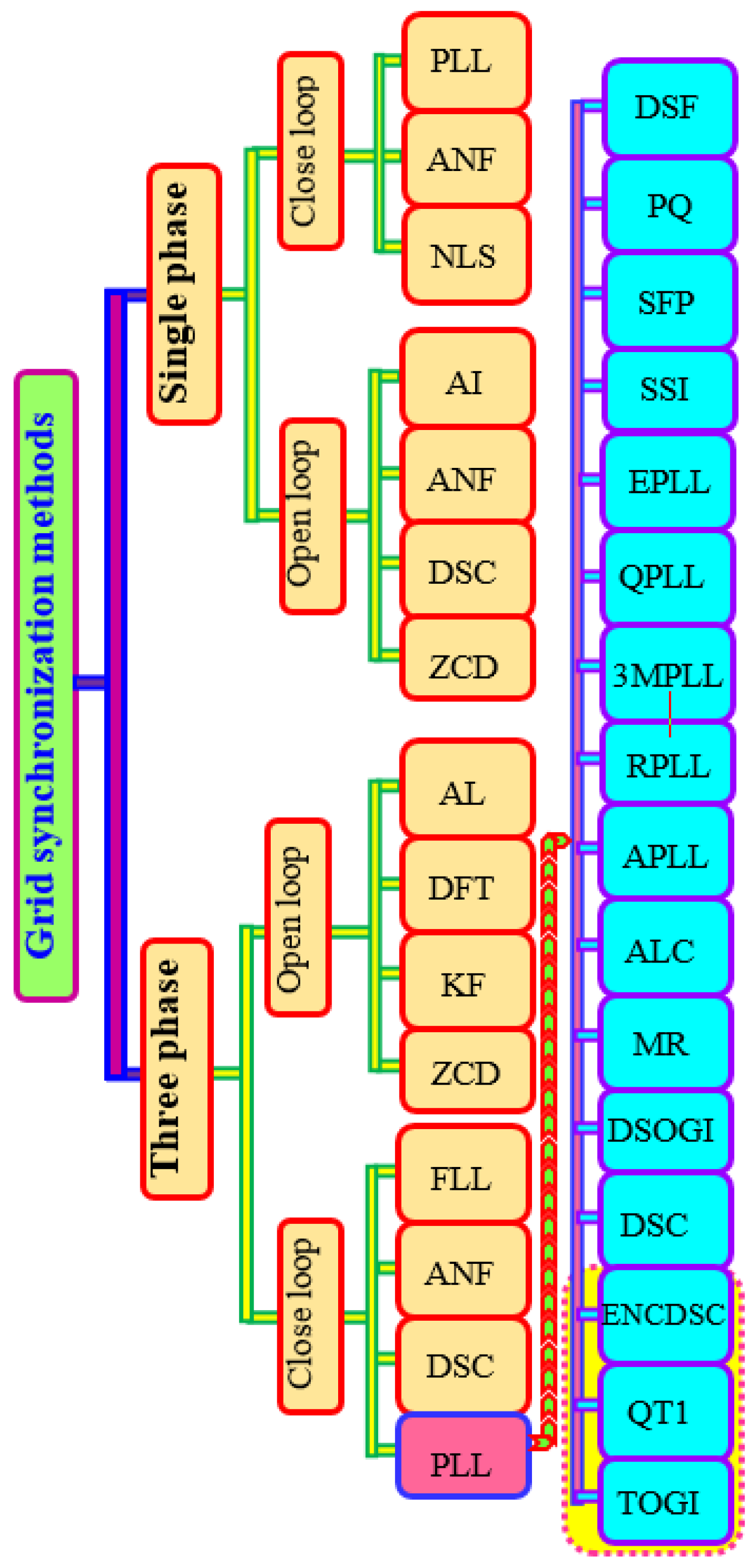
Figure 2.
Block diagram of: SOGI structure(a) and MSTOGI structure (b) [45].
Figure 2.
Block diagram of: SOGI structure(a) and MSTOGI structure (b) [45].
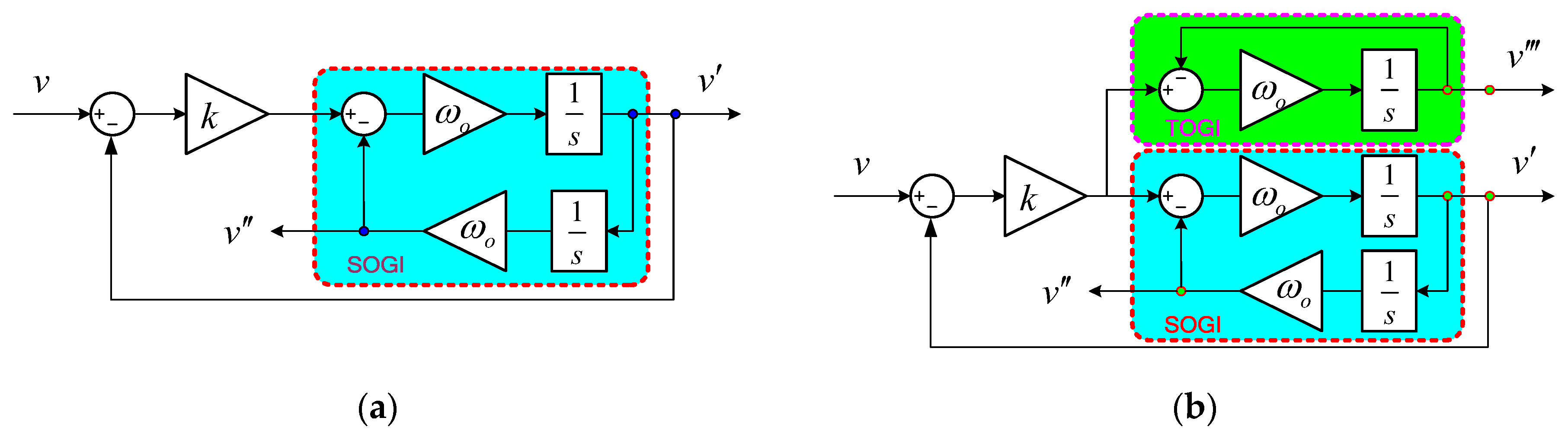
Figure 3.
Bode diagrams of: (a) and (b).

Figure 4.
Bode diagram of the third-order transfer function .

Figure 5.
Block diagram of MSTOGI configuration.
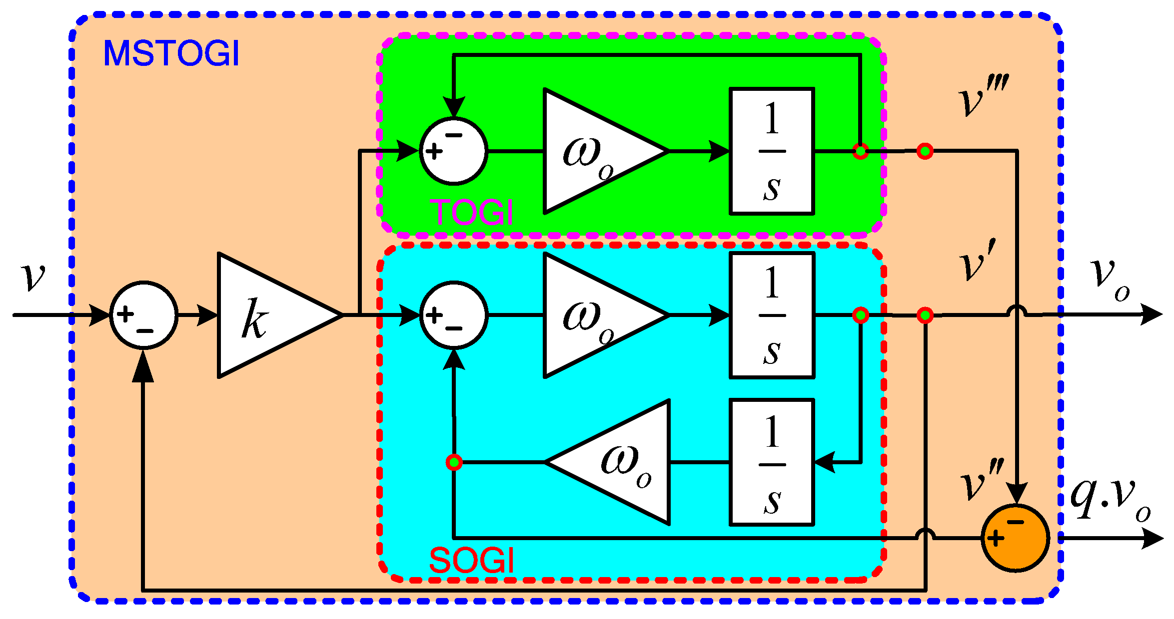
Figure 6.
Bode diagrams of .
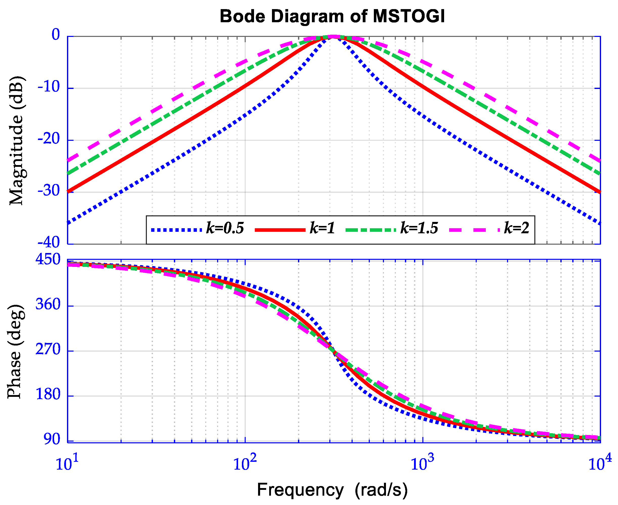
Figure 7.
Pole-zero maps of MSTOGI: (a) and (b).
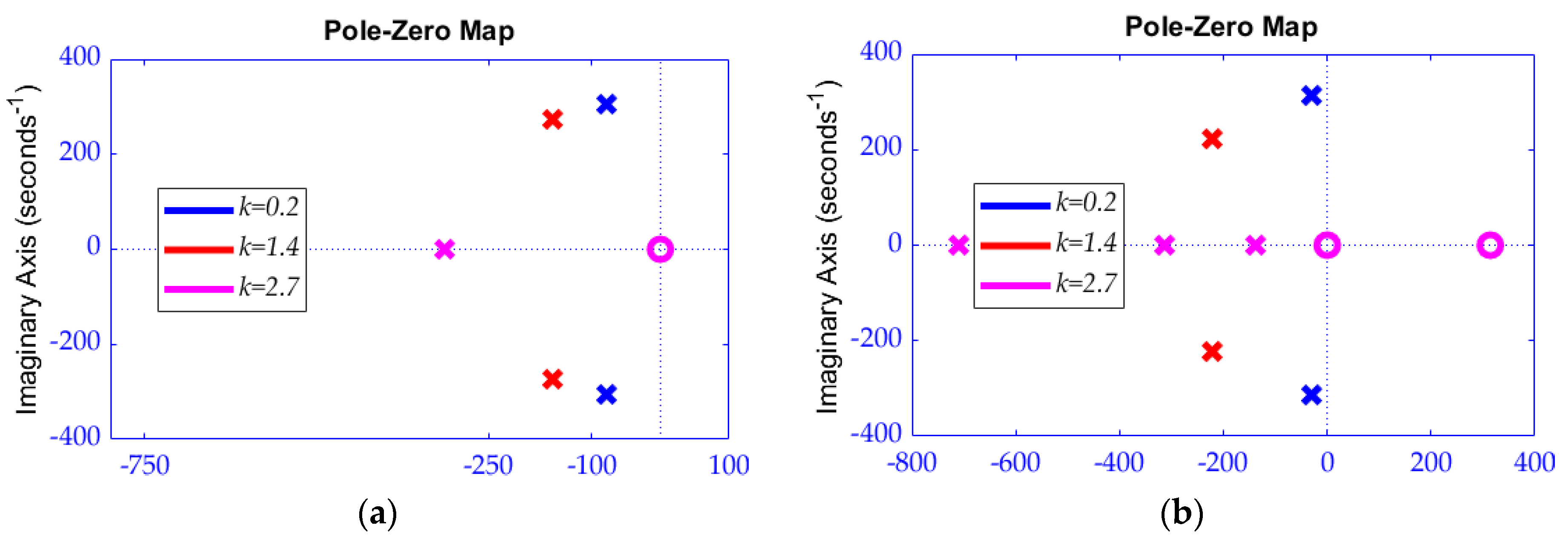
Figure 8.
Bloc structure of proposed MSTOGI-MQT1-PLL.
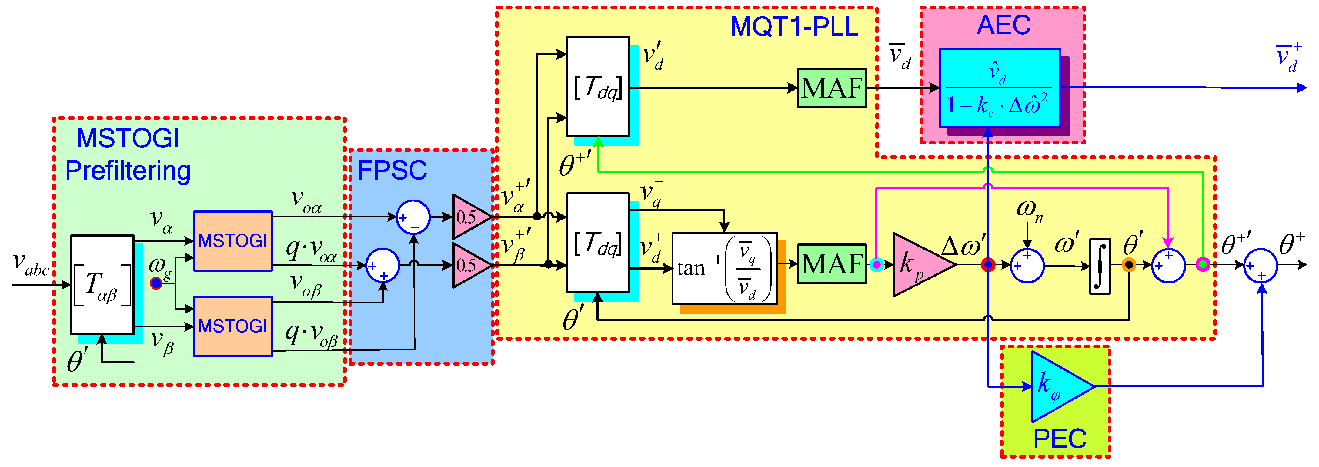
Figure 9.
Grid voltages: scenario 1.
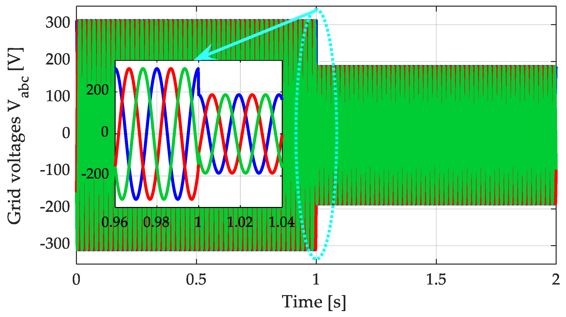
Figure 10.
DSOGI-PLL performance for scenario 1: αβ voltages (a), phase angle (b), frequency (c), and frequency error (d).
Figure 10.
DSOGI-PLL performance for scenario 1: αβ voltages (a), phase angle (b), frequency (c), and frequency error (d).
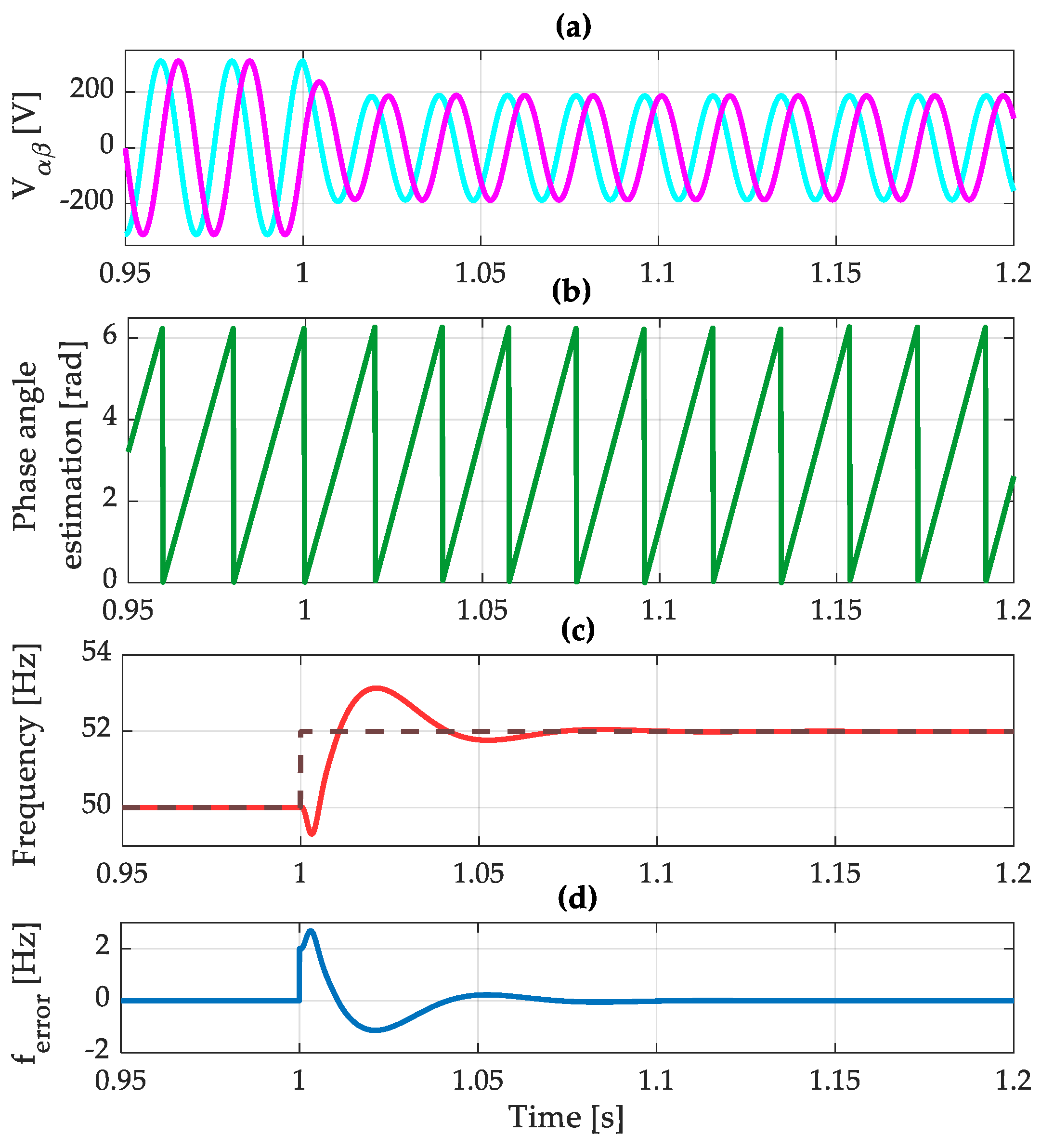
Figure 11.
CDSC-PLL performance for scenario 1: αβ voltages (a), phase angle (b), frequency (c), and frequency error (d).
Figure 11.
CDSC-PLL performance for scenario 1: αβ voltages (a), phase angle (b), frequency (c), and frequency error (d).

Figure 12.
MDSC_n-PLL performance for scenario 1: αβ voltages (a), phase angle (b), frequency (c), and frequency error (d).
Figure 12.
MDSC_n-PLL performance for scenario 1: αβ voltages (a), phase angle (b), frequency (c), and frequency error (d).

Figure 13.
Proposed MSTOGI-MQT1-PLL performance for scenario 1: αβ voltages (a), phase angle (b), frequency (c), and frequency error (d).
Figure 13.
Proposed MSTOGI-MQT1-PLL performance for scenario 1: αβ voltages (a), phase angle (b), frequency (c), and frequency error (d).
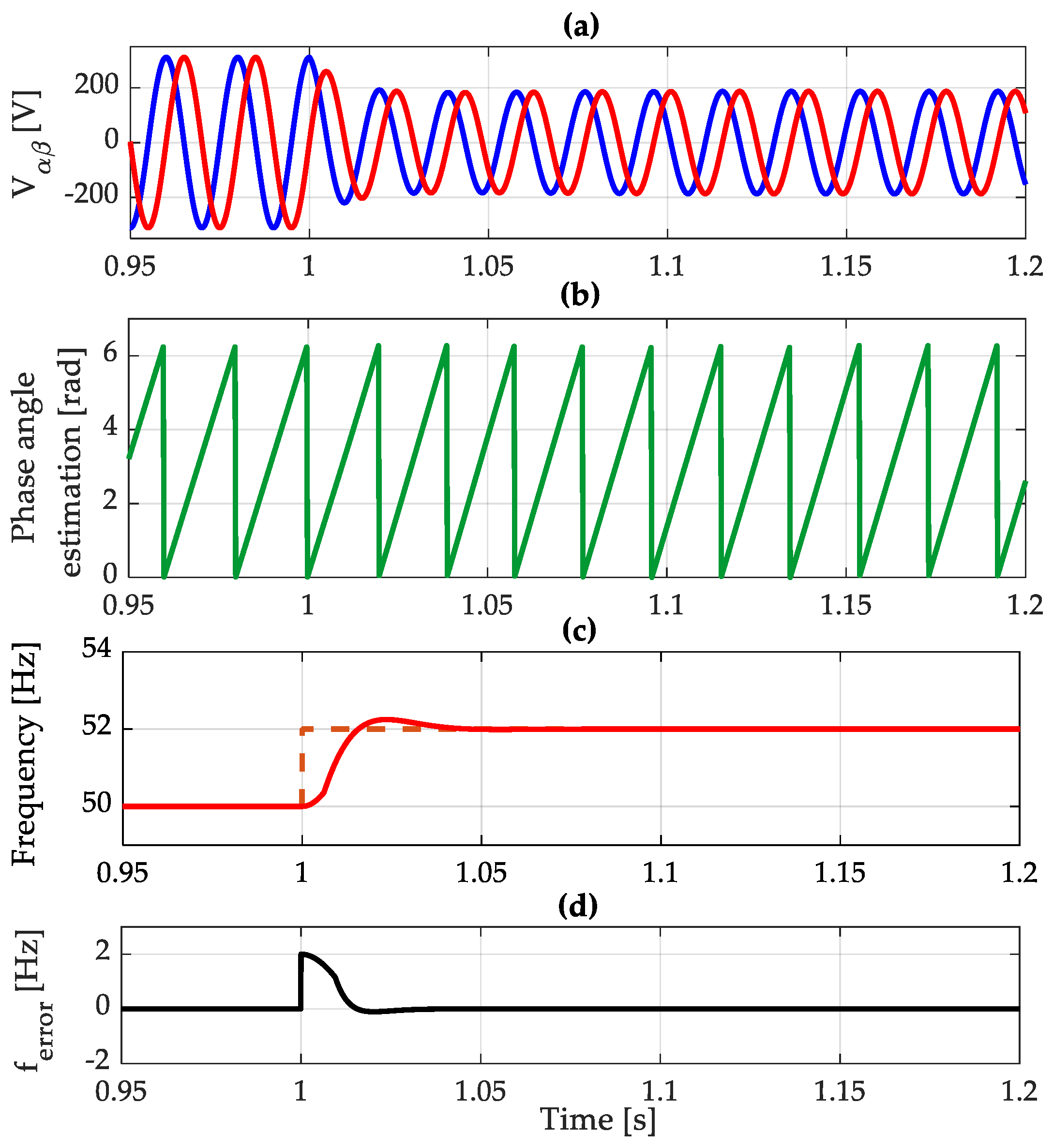
Figure 14.
Estimated frequency for all studied methods.
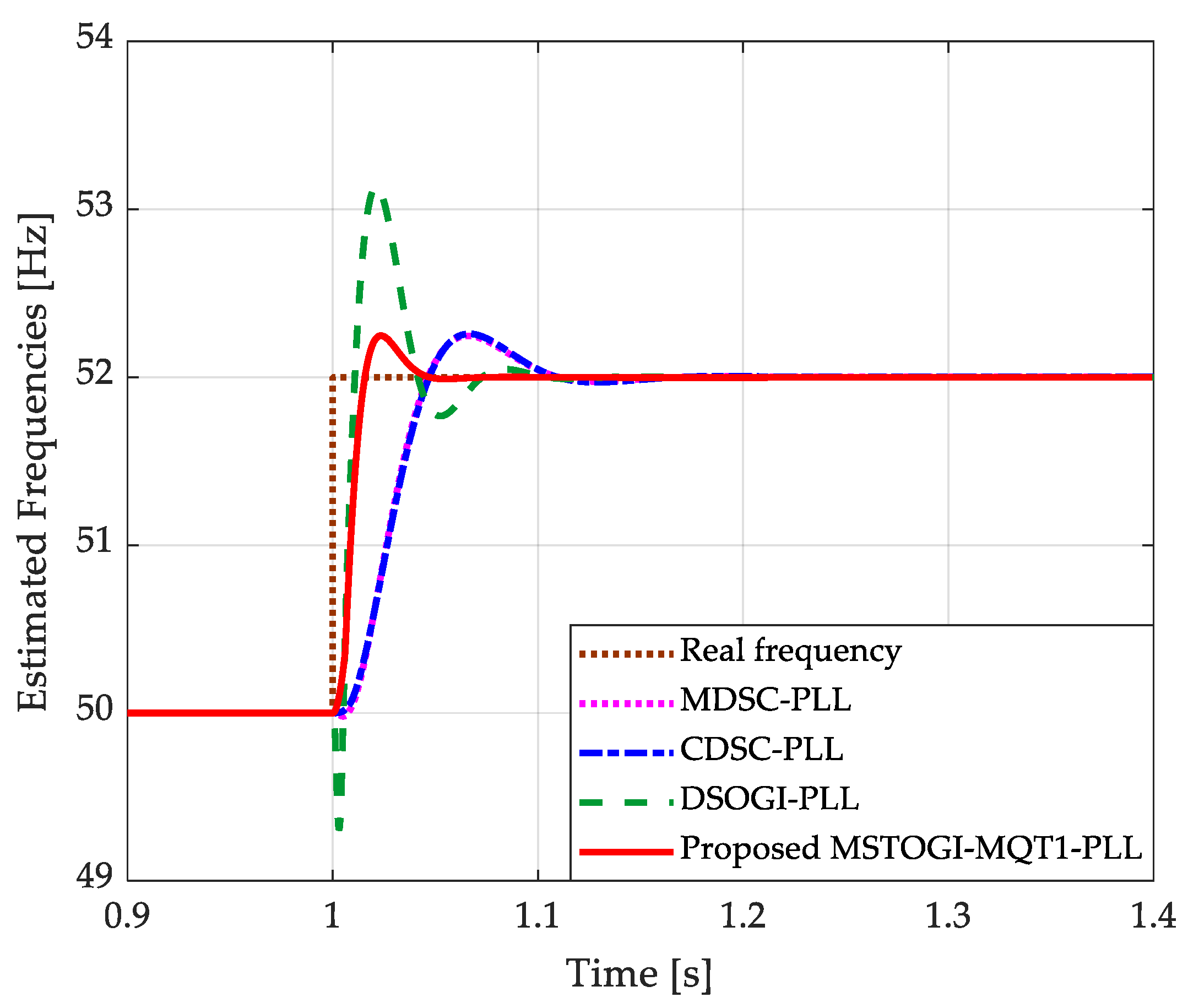
Figure 15.
Grid voltages: scenario 2.
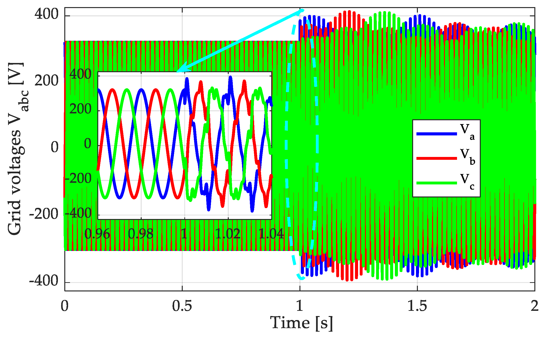
Figure 16.
Dynamic performance of the proposed MSTOGI-MQT1-PLL and the DSOGI-PLL.
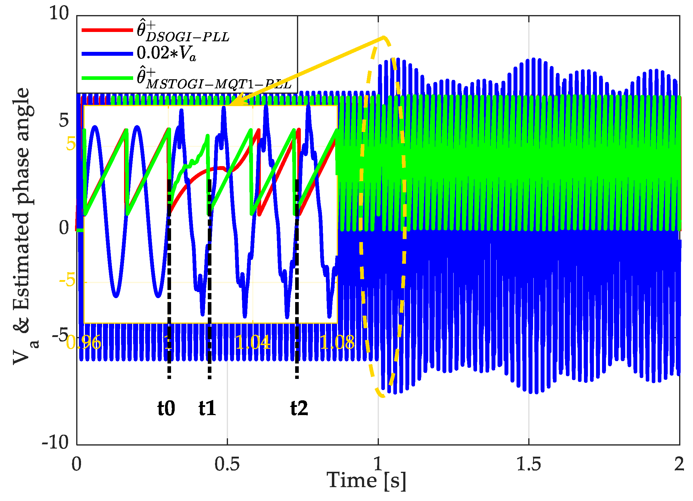
Figure 17.
Estimated frequency for all studied methods for scenario 2.
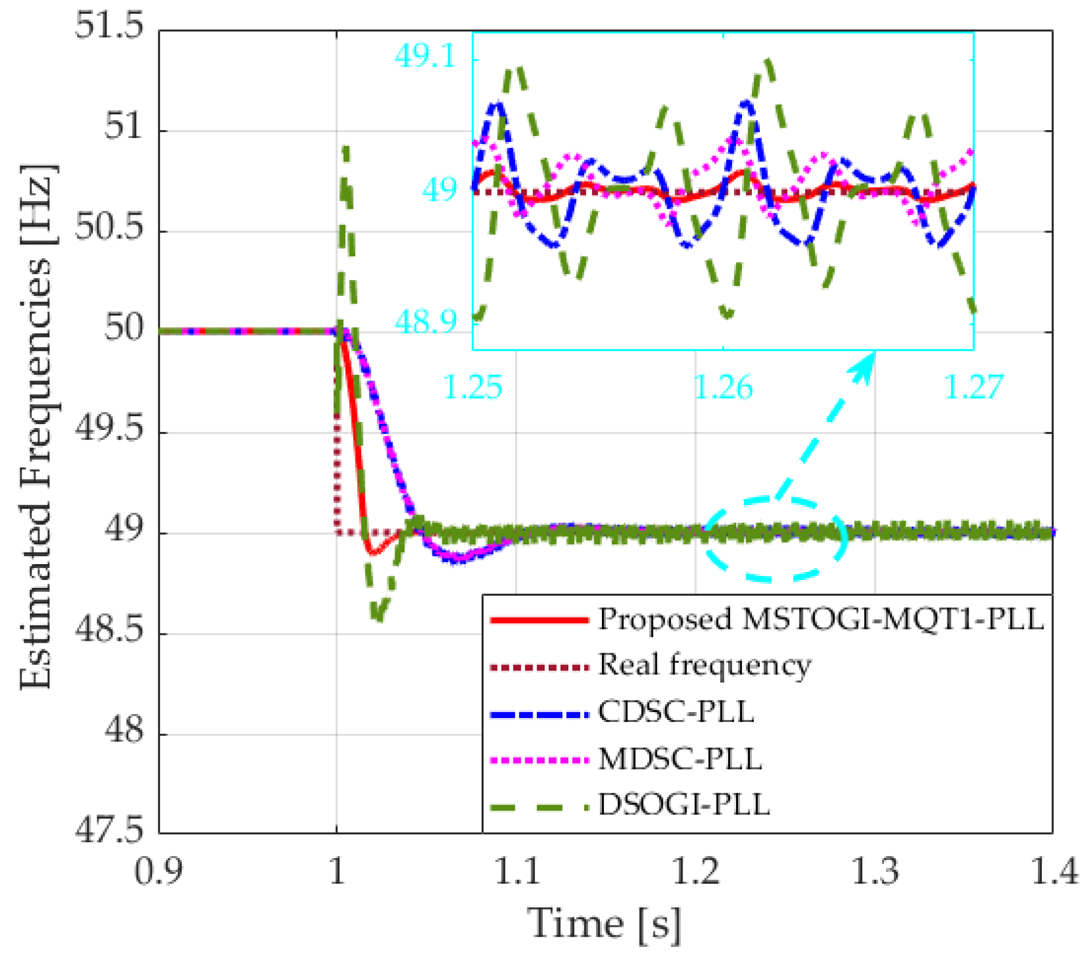
Figure 18.
Grid voltages: scenario 3.

Figure 19.
Estimated frequency for all studied methods for scenario 3.


Table 1.
Harmonic composition of scenario 2.
| Harmonic Order | THD (%) |
|---|---|
| 5th harmonic | 10 |
| 7th harmonic | 10 |
| 11th harmonic | 5 |
| 13th harmonic | 5 |
Table 2.
Summary of results.
| # | Grid Voltages | Frequency Overshoot | |||||
|---|---|---|---|---|---|---|---|
| - | Voltage Sag | Frequency Step | Harmonics | DSOGI-PLL | MDSC-PLL | CDSC-PLL | MSTOGI-MQT1-PLL |
| Scenario 1 | Symmetrical | +2 Hz | No | +1.1346 −0.6916 | +0.2463 −0.0197 | +0.2580 −0.0313 | +0.2272 −0.1009 |
| Scenario 2 | No | −1 Hz | Yes | +0.4325 −0.4165 | +0.0085 −0.1196 | +0.0908 −0.1302 | +0 −0.1041 |
| Scenario 3 | Asymmetrical | −1 Hz | Yes | +0.4424 −0.4275 | +0.0097 −0.1373 | +0.0917 −0.1369 | +0 −0.1083 |
Publisher’s Note: MDPI stays neutral with regard to jurisdictional claims in published maps and institutional affiliations. |
© 2022 by the authors. Licensee MDPI, Basel, Switzerland. This article is an open access article distributed under the terms and conditions of the Creative Commons Attribution (CC BY) license (https://creativecommons.org/licenses/by/4.0/).
Share and Cite
MDPI and ACS Style
Alturki, M.; Abbassi, R.; Albaker, A.; Jerbi, H. A New Hybrid Synchronization PLL Scheme for Interconnecting Renewable Energy Sources to an Abnormal Electric Grid. Mathematics 2022, 10, 1101. https://doi.org/10.3390/math10071101
AMA Style
Alturki M, Abbassi R, Albaker A, Jerbi H. A New Hybrid Synchronization PLL Scheme for Interconnecting Renewable Energy Sources to an Abnormal Electric Grid. Mathematics. 2022; 10(7):1101. https://doi.org/10.3390/math10071101
Chicago/Turabian StyleAlturki, Mansoor, Rabeh Abbassi, Abdullah Albaker, and Houssem Jerbi. 2022. "A New Hybrid Synchronization PLL Scheme for Interconnecting Renewable Energy Sources to an Abnormal Electric Grid" Mathematics 10, no. 7: 1101. https://doi.org/10.3390/math10071101
Note that from the first issue of 2016, this journal uses article numbers instead of page numbers. See further details here.