Article

Thermogravitational Convective Flow and Energy Transport in an Electronic Cabinet with a Heat-Generating Element and Solid/Porous Finned Heat Sink

1
Butakov Research Center, National Research Tomsk Polytechnic University, 634050 Tomsk, Russia
2
Department of Mathematics, Babeş-Bolyai University, 400084 Cluj-Napoca, Romania
3
Laboratory on Convective Heat and Mass Transfer, Tomsk State University, 634045 Tomsk, Russia
*
Author to whom correspondence should be addressed.
Mathematics 2022, 10(1), 34; https://doi.org/10.3390/math10010034
Submission received: 3 December 2021 / Revised: 17 December 2021 / Accepted: 20 December 2021 / Published: 23 December 2021
(This article belongs to the Special Issue State-of-the-Art Mathematical Applications in Europe)

Abstract

:
Heat transfer enhancement poses a significant challenge for engineers in various practical fields, including energy-efficient buildings, energy systems, and aviation technologies. The present research deals with the energy transport strengthening using the viscous fluid and solid/porous fins. Numerical simulation of natural convective energy transport of viscous fluid in a cooling cavity with a heat-generating element placed in a finned heat sink was performed. The heat-generating element is characterized by constant volumetric heat generation. The Darcy–Brinkman approach was employed for mathematical description of transport processes within the porous fins. The governing equations formulated using the non-primitive variables were solved by the finite difference method of the second-order accuracy. The influence of the fins material, number, and height on the flow structure and heat transfer was also studied. It was found that the mentioned parameters can be considered as control characteristics for heat transfer and fluid flow for the cooling system.

1. Introduction

Many different engineering fields demand the heat transfer enhancement that can be achieved using the extended heat transfer surfaces. Such an approach helps to develop energy-efficient buildings, modern energy and electronic systems, aviation technologies, and others. Nowadays, extended heat transfer surfaces are widely used in different engineering applications [1,2,3,4,5]. There are some published researches on convective heat transport augmentation in chambers with a fins system [3,4,5,6,7,8,9,10,11,12]. Thus, Hatami [6] has studied thermal convection in a rectangular cabinet with two isothermal fins placed on the lower adiabatic surface under an influence of cold upper border. By using Pak and Cho relation for nanosuspension viscosity and Maxwell–Garnett relation for heat conductivity, the formulated partial differential equations could be worked out with the FlexPDE commercial code. It has been found that an increase in the fins’ height results in a higher mean Nusselt number. Siavashi et al. [7] computationally scrutinized free convection in a differentially warmed square chamber filled with copper–water nanoliquid, and placed porous fins on the left vertical hot border. By employing the Corcione’s correlations for nanosuspension viscosity and thermal conductivity with the two-phase nanofluid model, the governing partial differential equations could be worked out by the finite volume technique. It has been revealed that, for high Darcy numbers, energy transport strength can be increased with fins number and fins length, while for low Darcy numbers, one can find the opposite effect. Hejri and Malekshah [8] have scrutinized computationally natural convective energy transport and entropy production in a rectangular cabinet saturated with CuO–water nanoliquid under an influence of isothermally heated fins and isothermally cooled vertical and upper cavity walls. The used a single-phase nanofluid model with the Koo–Kleinstreuer–Li approach for nanofluid thermal conductivity, and numerically worked out the viscosity. Authors have found that a reduction in the aspect ratio of fins characterizes the heat transfer strength diminution. Massoudi et al. [9] examined computationally MHD natural convection of MWCNT–H2O nanosuspension in an inclined T-shaped enclosure with isothermal trapezoidal fins mounted on the lower border. Numerical analysis was conducted by employing the single-phase nanosuspension approach with the Brinkman model to work out viscosity, and the Xue approach was conducted to work out thermal conductivity on the basis of the COMSOL Multiphysics commercial software. Authors have ascertained an increase in the mean Nusselt number with fins height. Furthermore, the fins location and shape, in combination with the chamber inclination, have an essential influence on the heat transport rate. Astanina et al. [10] have computationally investigated free convective energy transference in a porous chamber saturated with variable viscosity liquid under an impact of heat-producing source and finned heat sink. Using the created computational code, analysis has shown that the fins number plays an essential role in energy removal from the heated element for the passive cooling systems.
Natural convection with the second thermodynamic law for alumina–water nanoliquid in a differentially warmed chamber with isothermally heated fins of various shapes mounted on left vertical hot wall under the influence of uniform Lorentz force has been investigated by Yan et al. [11]. By employing single-phase nanosuspension approach with the Koo–Kleinstreuer model for nanofluid heat conductivity and viscosity, the governing equations could be worked out using the finite volume method. Authors have found that the energy transport can be intensified by attaching the inclined fins. Gireesha et al. [12] have numerically analyzed an influence of the hybrid nanofluid on liquid motion and energy transfer over a porous fin moving with constant velocity. The single-phase nanofluid model with Brinkman and Maxwell relations for viscosity and heat conductivity, in combination with one-dimensional approximation, has been solved using the Runge–Kutta–Fehlberg technique for ordinary differential equations. It has been found that hybrid nanofluid helps to intensify the energy transport. Buonomo et al. [5] have generalized the previous research to the local thermal non-equilibrium model for the porous fin in the case of natural convection and heat radiation. The defined ordinary differential relations were worked out using the Adomian decomposition method. Authors have revealed that low Rayleigh numbers and intensive external cooling reflect a possibility to use the local thermal equilibrium approach. Some interesting results can also be found in [13,14,15,16,17,18].
This brief review illustrates the actuality of the considered topic, but there are no papers that analyze the influence of porous–solid fins on heat-generating element within the highly heat-conducting heat sink in a closed cooling chamber. Therefore, the aim of the research is a computational simulation of heat transfer performance in a closed cooling cabinet saturated with viscous fluid under an impact of porous/solid fins on the heat-generating element within the heat sink.

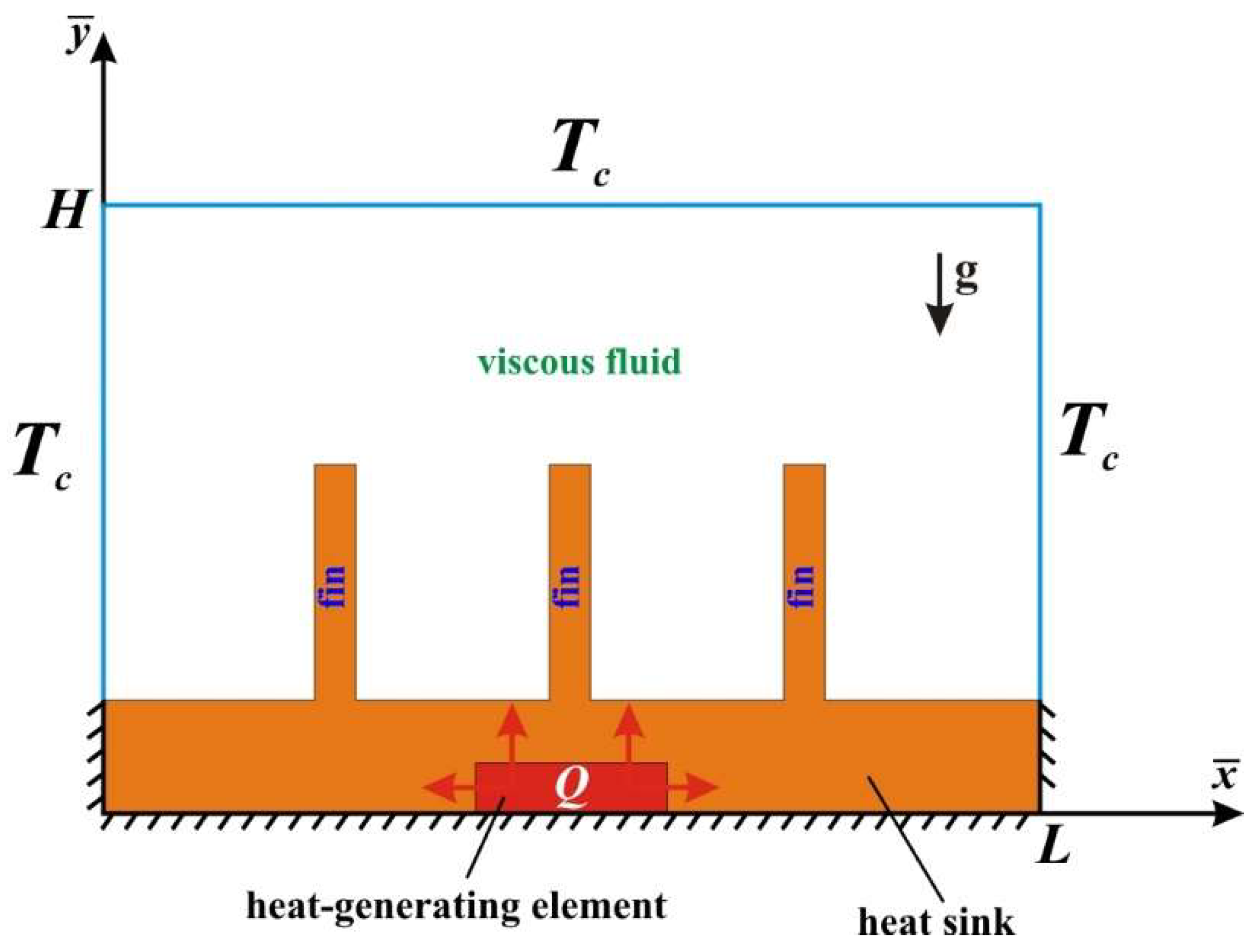
2. Mathematical Simulation

Herein, we analyze the viscous, laminar, incompressible, and conjugate convective energy transfer and liquid circulation in a closed hermetic electronic cabinet with a thermally producing source placed inside a finned heat sink. The cooling system is shown in Figure 1, where the liquid (water) is circulated within the chamber. To have the impact of buoyancy, the cabinet requires to be regarded in vertical location, since the analysis is of natural convection. Let x ¯ and y ¯ be the coordinate axes in horizontal and vertical directions, respectively, with u ¯ and v ¯ denoting the corresponding velocity components. Let the temperature of vertical and upper horizontal walls be denoted by Tc. The density changes are modeled using the Boussinesq approach [3,4,10]. The local heater is a heat-conducting solid element with a constant volumetric heat generation Q. The temperature of the solid structure equals the temperature of the liquid phase for the porous fins, and the local thermal equilibrium approach is employed. The transport processes in porous fins are modeled on the basis of the Brinkman–extended Darcy approximation.
The governing equations representing the liquid circulation and energy transport are as follows [3,4,10].
For the viscous fluid
u ¯ x ¯ + v ¯ y ¯ = 0
ρ ( u ¯ t + u ¯ u ¯ x ¯ + v ¯ u ¯ y ¯ ) = p x ¯ + μ ( 2 u ¯ x ¯ 2 + 2 u ¯ y ¯ 2 )
ρ ( v ¯ t + u ¯ v ¯ x ¯ + v ¯ v ¯ y ¯ ) = p y ¯ + μ ( 2 v ¯ x ¯ 2 + 2 v ¯ y ¯ 2 ) + ρ g β ( T T c )
T t + u ¯ T x ¯ + v ¯ T y ¯ = k f ( ρ c ) f ( 2 T x ¯ 2 + 2 T y ¯ 2 )
For the solid fins and solid heat sink
( ρ c ) s T t = k s ( 2 T x ¯ 2 + 2 T y ¯ 2 )
For the heat-generating element
( ρ c ) h s T t = k h s ( 2 T x ¯ 2 + 2 T y ¯ 2 ) + Q
For the porous fins
u ¯ x ¯ + v ¯ y ¯ = 0
ρ ( 1 ε u ¯ t + u ¯ ε 2 u ¯ x ¯ + v ¯ ε 2 u ¯ y ¯ ) = p x ¯ + μ ε ( 2 u ¯ x ¯ 2 + 2 u ¯ y ¯ 2 ) μ K u ¯
ρ ( 1 ε v ¯ t + u ¯ ε 2 v ¯ x ¯ + v ¯ ε 2 v ¯ y ¯ ) = p y ¯ + μ ε ( 2 v ¯ x ¯ 2 + 2 v ¯ y ¯ 2 ) μ K v ¯ + ρ g β ( T T c )
η T t + u ¯ T x ¯ + v ¯ T y ¯ = k p m ( ρ c ) f ( 2 T x ¯ 2 + 2 T y ¯ 2 )
where η = ε + ( 1 ε ) ( ρ c ) s p m ( ρ c ) f is the overall heat capacity ratio and k p m = ε k f + ( 1 ε ) k s p m is the thermal conductivity of porous medium.
Including the stream function ( u ¯ = ψ ¯ y ¯ , v ¯ = ψ ¯ x ¯ ) , vorticity ( ω ¯ = v ¯ x ¯ u ¯ y ¯ ) , and non-dimensional parameters:
x = x ¯ / H ,   y = y ¯ / H ,   τ = t g β Δ T / H ,   θ = ( T T c ) / Δ T , u = u ¯ / g β Δ T H ,   v = v ¯ / g β Δ T H ,   ψ = ψ ¯ / g β Δ T H 3 ,   ω = ω ¯ H / g β Δ T
The control non-dimensional equations are as follows [3,4,10].
For the viscous fluid
2 ψ x 2 + 2 ψ y 2 = ω
ω τ + ψ y ω x ψ x ω y = Pr R a ( 2 ω x 2 + 2 ω y 2 ) + θ x
θ τ + u θ x + v θ y = 1 R a Pr ( 2 θ x 2 + 2 θ y 2 )
For the solid fins and solid heat sink
θ τ = α s / α f R a Pr ( 2 θ x 2 + 2 θ y 2 )
For the heat-generating element
θ τ = α h s / α f R a Pr ( 2 θ x 2 + 2 θ y 2 + 1 )
For the porous fins
2 ψ x 2 + 2 ψ y 2 = ω
ε ω τ + ψ y ω x ψ x ω y = ε Pr R a ( 2 ω x 2 + 2 ω y 2 ε ω D a ) + ε 2 θ x
θ τ + u θ x + v θ y = k p m / k f R a Pr ( 2 θ x 2 + 2 θ y 2 )
The employed additional conditions are
τ = 0 : ψ ( x , y , 0 ) = 0 , ω ( x , y , 0 ) = 0 , θ ( x , y , 0 ) = 0 τ > 0 : θ x = 0   at   x = 0 ,   x = L / H   and   0 y h / H θ y = 0   at   y = 0 ,   0 x L / H ψ = 0 ,   ω = 2 ψ x 2 ,   θ = 0   at   x = 0 ,   x = L / H   and   h / H y 1 ψ = 0 ,   ω = 2 ψ y 2 ,   θ = 0   at   y = 1   and 0 x L / H { θ h s = θ s k h s k s θ h s n = θ s n   at   heater   surface ψ = 0 ,   ω = 2 ψ n 2 ,   { θ f = θ s θ f n = λ s λ f θ s n   at   finned   heat   sink   surface { θ f = θ p m , θ f n = k p m k f θ p m n , { ψ f = ψ p m , ψ f n = ψ p m n , { ω f = ω p m , ω f n = ω p m n | at   porous fins / fluid interface ψ = 0 ,   ω = 2 ψ y 2 ,   { θ s = θ p m , θ s n = k p m k s θ p m n | at   porous   fins / solid   heat sink   interface
Here, R a = ρ f g β Δ T H 3 / ( α f μ ) is the Rayleigh number, Pr = μ / ( ρ f α f ) is the Prandtl number, and D a = K / H 2 is the Darcy number.

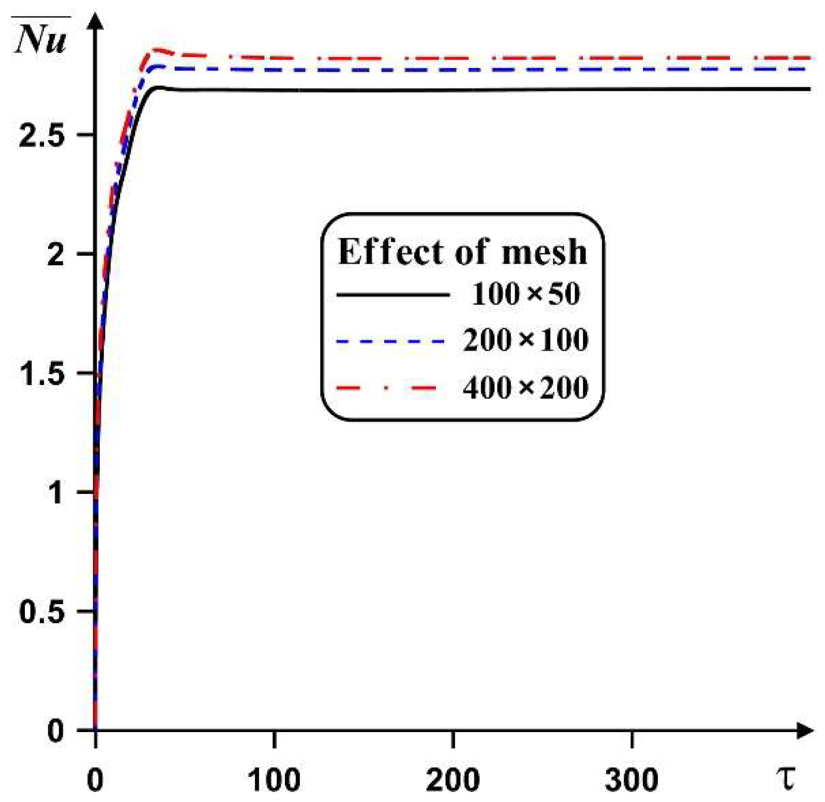
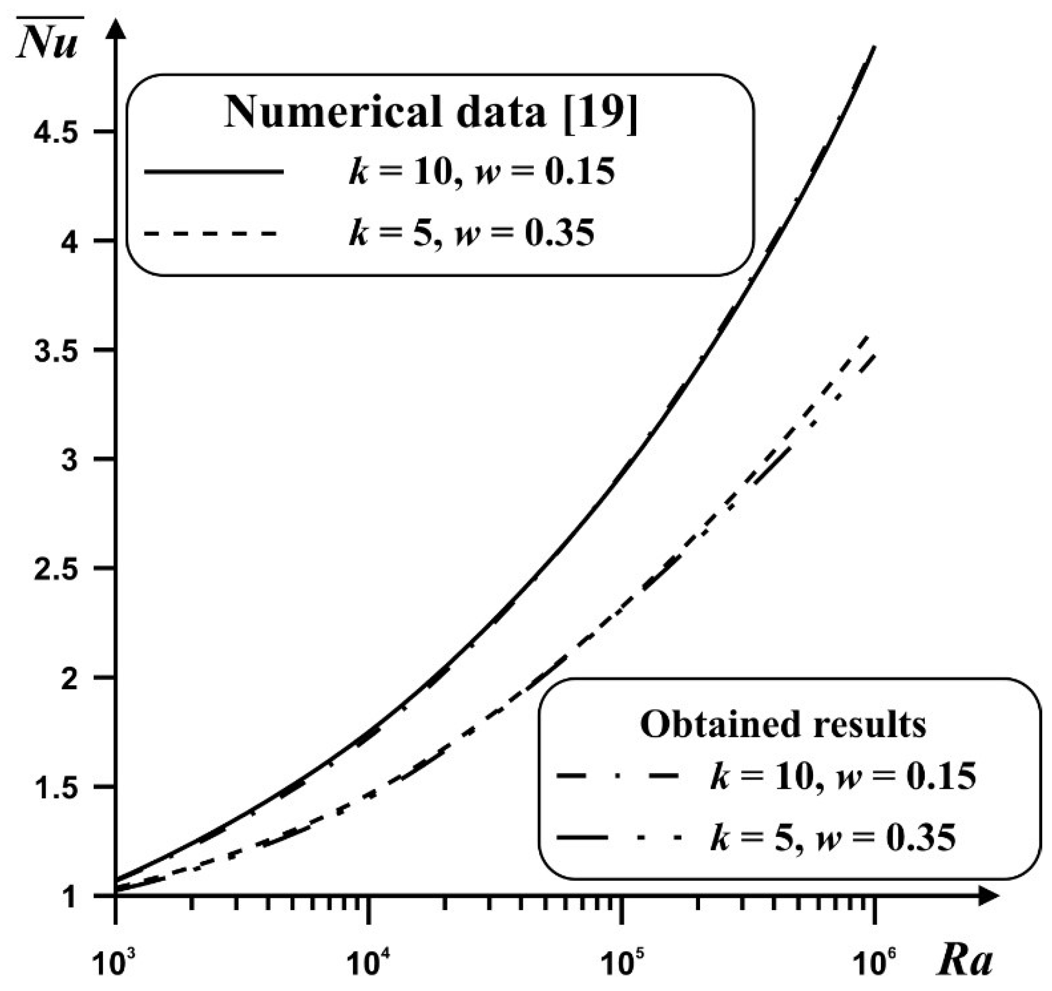
3. Solution Technique

The formulated partial differential Equations (12)–(19) with additional conditions (20) have been worked out by the finite difference technique of the second-order accuracy using the uniform mesh [3,4,10]. For the discretization of the convective and diffusive members, we applied the finite differences of the second-order accuracy. The energy and vorticity equations were worked out using the Samarskii locally one-dimensional technique. The approximated relations were resolved by the Thomas method. Equations (12) and (17) were approximated employing the five-point differences. Obtained relations were carried out by the successive over relaxation technique. The described numerical procedure was included in the in-house computational code developed using C++ programming language. The created computational code was verified comprehensively using numerical data of other authors and mesh sensitivity analysis. It should be noted that the developed code can solve the conjugate natural convection problems for different fins numbers, fins materials, and geometry in laminar regimes of fluid flow and heat transfer.
The developed numerical algorithm was then verified for different grids at Ra = 105 and Pr = 6.82. Figure 2 demonstrates an influence of the grid characteristics on the mean Nusselt number at the heat sink surface.
Considering this impact of the mesh characteristics, the uniform mesh of 200 × 100 elements were chosen for further analysis.
Validation of the created computational program was performed for different model problems. The first problem [19] is the conjugate thermal convection in a closed cabinet with a thermally conducting wall of finite thickness. Dependences of the mean Nusselt number on the Rayleigh number, heat conductivity ratio, and solid wall thickness in comparison with numerical data [19] are shown in Figure 3.
In the case of porous medium, the validation was performed for the problem of natural convection of viscous liquid in a differentially heated cabinet which was partially saturated with porous material. Figure 4 demonstrates a good agreement between the obtained results and computational data [20] for streamlines and isotherms at Da = 10−5 and Ra = 106.
This performed validation demonstrates that the developed numerical code helps to correctly solve the conjugate convective heat transfer problems for clear and porous media. Therefore, this code was employed for calculations of convective–conductive energy transfer in a closed electronic cabinet, as presented in Figure 1.

4. Results and Discussion

Numerical solution of the considered problem was obtained for Ra = 105, Pr = 6.82, Da = 10−5, and ε = 0.8, as well as for a different fins number, fins material, and fins height. It should be noted that the porosity of a porous medium is defined as the fraction of the total volume of the medium that is occupied by void space [21]. It is well known that, for natural media, the porosity does not normally exceed 0.6. In the present study, the porous material is a man-made material lsuch as metallic foam, where porosity can approach the value 1. The main focus is on the influence of the solid and porous fins on flow structure and energy transport within the closed cabinet.
Authors should highlight that all results were obtained using the developed computational code. This code is a home-made program using non-primitive variables, such as stream function and vorticity (see Equations (12)–(19)). An application of such variables helps to reduce the number of equations as well as the computational time. Moreover, in the present research, the conjugated natural convection problem was solved with boundary conditions of a forth kind by illustrating an equality of temperatures and heat fluxes at interfaces. From the mathematical point of view, an approximation of governing equations and boundary conditions for space coordinates was performed using the second order of accuracy.
Figure 5 shows the streamlines and isotherms within the closed chamber with solid fins. Solid fins are natural obstacles to the liquid flow, which can be confirmed by the formation of reverse flows near the surfaces of these fins. The development of thermal plumes above the fins occurs due to the high thermal conductivity of the material of these solid fins. Material of the solid fins and heat sink is copper. The presence of a solid fin directly above the local heater reflects the ability to form a thermal plume and, as it might seem, to dissipate energy more intensively. If the fins are located at the periphery relative to the energy source, a downward flow with a cold two-dimensional plume from the upper cooling wall is formed in the central part, which also initiates cooling of the energy source. Furthermore, an inclusion of solid fins characterizes a complication of flow structures, namely, a transition between one, two, and three fins reflects a transition between two, four, and eight vortices. The considered constant value of the volumetric heat generation flux in a heater means that a thermal plume cannot be formed in a viscous fluid over the heater and that the descending flow from the upper cooled wall cannot interact (Figure 5b). In the case of three fins, the flow structure is too complex with four major eddies and four secondary eddies of less scale, but the symmetry of the flow structure characterizes a formation of steady mode. Moreover, one can find an interesting interaction between the central thermal plume and two side thermal plumes in the case of two and three fins. The presence of central descending flow illustrates an attraction between the two-side thermal plumes (Figure 5b), while the presence of the central ascending flow illustrates a repulsion between the two-side thermal plumes (Figure 5c).
An introduction of porous fins characterizes a formation of a flow structure with less resistance from these fins. It should be noted that material of porous fins is the copper foam with Da = 10−5 and ε = 0.8. It should be noted that fins can be considered as thermal bridges for the formation of thermal plumes, but these bridges are permeable and such a structure helps to intensify the energy removal because the surface of such a porous fin is greater than the surface of a solid fin. As previously mentioned above, for the solid fins, an addition of fins leads to a formation of additional eddies in the closed cabinet (see Figure 5a,b and Figure 6a,b). However, in the case of three porous fins, the hydrodynamic situation is changed, namely, a permeability of porous fins results in a combination of side vortices due to a combination of thermal plumes over these fins. As a result, a formation of only the thermal plume over the central part can reduce the energy removal from the heater in comparison with the two fins. Still, the flow structures for one and two fins in the case of solid and porous material are similar.
Figure 7 demonstrates the time dependences of the mean heater temperature on fins number and height for solid and porous materials. As expected, the addition of fins helps to reduce the heater temperature, but an increase in the fins number has a non-monotonic influence on the heater temperature. At the same time, an increase in the fins height for the solid material results in a reduced heater temperature, while for porous material, one can reveal a temperature diminution for one and two fins. However, for three fins, the behavior is opposite. It should be noted that more intensive cooling of the heater is for two fins when central descending cooling flow interacts with the bottom solid plate. By comparing solid and porous fins, it is possible to conclude that porous permeable obstacles help to strongly decrease the heater temperature, but the influence of the fins number and fins height is non-monotonic.

5. Conclusions

This research considers the natural convection circulation and energy transfer of viscous fluid in a closed electronic cabinet with heat-producing source and finned heat sink. Numerical analysis was conducted by employing the created computational software. The developed in-house computational code using C++ programming language was verified comprehensively on the basis of the mesh sensitivity analysis and numerical data of other authors. It should be noted that usage of non-primitive variables helps to reduce essential computational time and obtain the correct physical results. The influence of fins number, fins height, and fins material on the circulation structure and energy transport was studied. Taking into account the performed detailed analysis, the obtained outcomes are as follows:
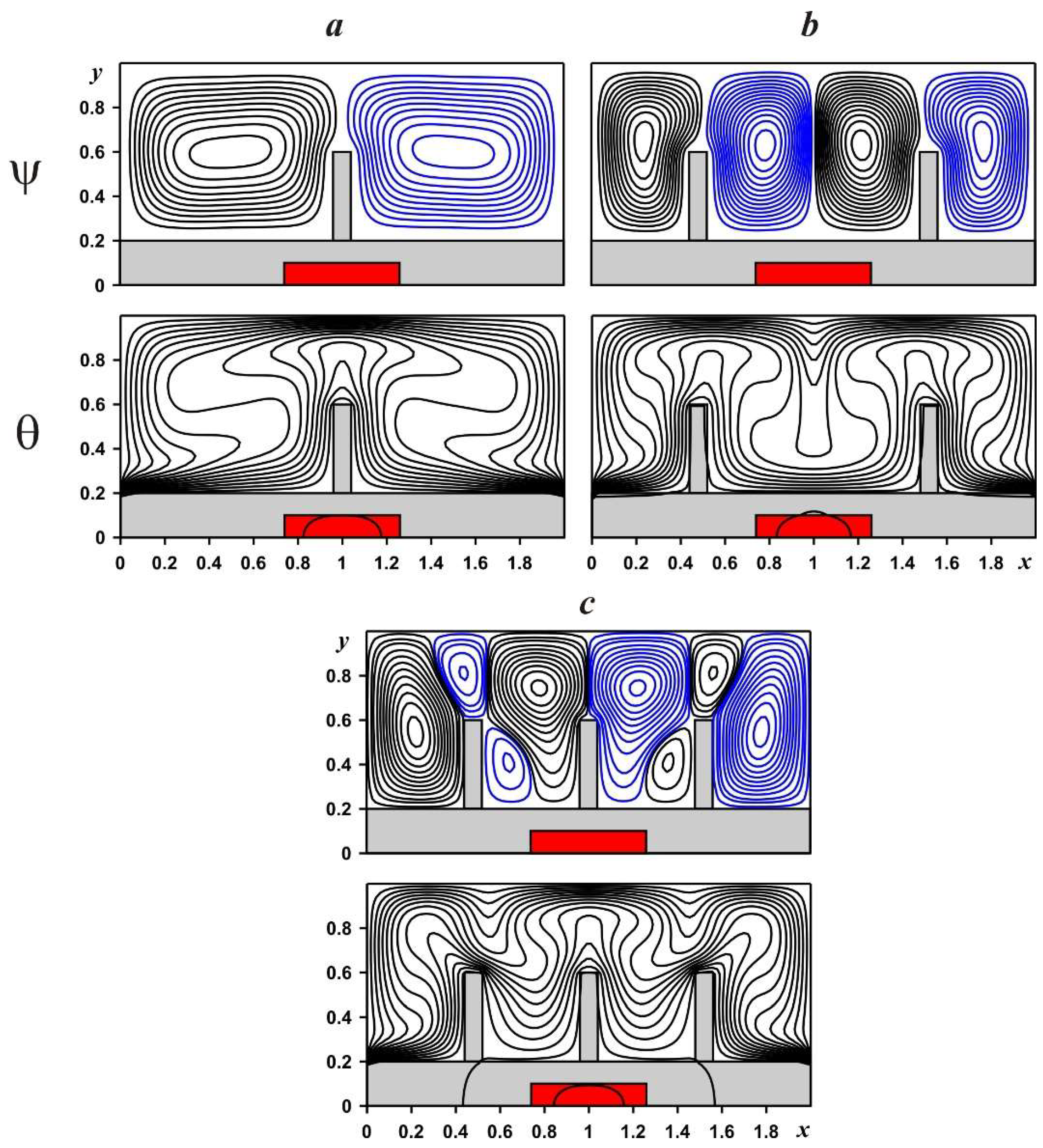
An addition of fins changes the motion structure and energy transfer. In the case of solid material of fins, a growth of the fins number results to a complication of flow structure, while for the porous foam flow nature can be simplified due to the permeability of the fins;
A growth of the fins height illustrates more essential average heater temperature reduction for the solid fins, while in the case of porous fins, such influence can be reversed;
An increase in the fins number characterizes a non-monotonic influence on the mean heater temperature. Namely, more essential cooling of the heater occurs in the case of two fins.

Author Contributions

Conceptualization, I.P. and M.A.S.; methodology, M.A.S.; formal analysis, X.H.K.L. and M.A.S.; investigation, X.H.K.L. and M.A.S.; writing—original draft preparation, X.H.K.L., I.P. and M.A.S.; writing—review and editing, X.H.K.L., I.P. and M.A.S.; supervision, M.A.S. All authors have read and agreed to the published version of the manuscript.

Funding

The work was supported by the Grants Council (under the President of the Russian Federation), Grant No. MD-5799.2021.4.

Institutional Review Board Statement

Not applicable.

Informed Consent Statement

Not applicable.

Data Availability Statement

All data are presented in this article.

Conflicts of Interest

The authors declare no conflict of interest.

Nomenclature

cheat capacity
DaDarcy number
gacceleration due to gravity
hheight of the bottom solid plate
Helectronic cabinet height
kthermal conductivity
Kporous medium permeability
Lelectronic cabinet length
Nfins number
NuNusselt number
ppressure
PrPrandtl number
Qvolumetric heat generation density
RaRayleigh number
ttime
Ttemperature
Tccooled wall temperature
u ¯ , v ¯ velocity components
u, vnon-dimensional velocity components
x ¯ , y ¯ Cartesian coordinates
x, ynon-dimensional Cartesian coordinates
Greek symbols
αthermal diffusivity
βthermal expansion parameter
δnon-dimensional fins height
εporous medium porosity
θnon-dimensional temperature
μdynamic viscosity
ρdensity
τnon-dimensional time
ψ ¯ stream function
ψnon-dimensional stream function
ω ¯ vorticity
ωnon-dimensional vorticity
Subscripts
ffluid
hsheat source
pmporous medium
ssolid
spmsolid matrix of porous medium

References

  1. Nguyen, D.H.; Ahn, H.S. A comprehensive review on micro/nanoscale surface modification techniques for heat transfer enhancement in heat exchanger. Int. J. Heat Mass Transf. 2021, 178, 121601. [Google Scholar] [CrossRef]
  2. Mousa, M.H.; Miljkovic, N.; Nawaz, K. Review of heat transfer enhancement techniques for single phase flows. Renew. Sustain. Energy Rev. 2021, 137, 110566. [Google Scholar] [CrossRef]
  3. Bondareva, N.S.; Sheremet, M.A. Conjugate heat transfer in the PCM-based heat storage system with finned copper profile: Application in electronics cooling. Int. J. Heat Mass Transf. 2018, 124, 1275–1284. [Google Scholar] [CrossRef]
  4. Asl, K.A.; Hossainpour, S.; Rashidi, M.M.; Sheremet, M.A.; Yang, Z. Comprehensive investigation of solid and porous fins influence on natural convection in an inclined rectangular enclosure. Int. J. Heat Mass Transf. 2019, 133, 729–744. [Google Scholar]
  5. Buonomo, B.; Cascetta, F.; Manca, O.; Sheremet, M. Heat transfer analysis of rectangular porous fins in local thermal non-equilibrium model. Appl. Therm. Eng. 2021, 195, 117237. [Google Scholar] [CrossRef]
  6. Hatami, M. Numerical study of nanofluids natural convection in a rectangular cavity including heated fins. J. Mol. Liq. 2017, 233, 1–8. [Google Scholar] [CrossRef]
  7. Siavashi, M.; Yousofvand, R.; Rezanejad, S. Nanofluid and porous fins effect on natural convection and entropy generation of flow inside a cavity. Adv. Powder Technol. 2018, 29, 142–156. [Google Scholar] [CrossRef]
  8. Hejri, S.; Malekshah, E.H. Cooling of an electronic processor based on numerical analysis on natural convection and entropy production over a dissipating fin equipped with copper oxide/water nanofluid with Koo-Kleinstreuer-Li model. Therm. Sci. Eng. Prog. 2021, 23, 100916. [Google Scholar] [CrossRef]
  9. Massoudi, M.D.; Hamida, M.B.B.; Almeshaal, M.A.; Hajlaoui, K. The influence of multiple fins arrangement cases on heat sink efficiency of MHD MWCNT-water nanofluid within tilted T-shaped cavity packed with trapezoidal fins considering thermal emission impact. Int. Commun. Heat Mass Transf. 2021, 126, 105468. [Google Scholar] [CrossRef]
  10. Astanina, M.S.; Rashidi, M.M.; Sheremet, M.A.; Lorenzini, G. Cooling system with porous finned heat sink for heat-generating element. Transp. Porous Media 2020, 133, 459–478. [Google Scholar] [CrossRef]
  11. Yan, S.R.; Pordanjani, A.H.; Aghakhani, S.; Goldanlou, A.S.; Afrand, M. Managment of natural convection of nanofluids inside a square enclosure by different nano powder shapes in presence of Fins with different shapes and magnetic field effect. Adv. Powder Technol. 2020, 31, 2759–2777. [Google Scholar] [CrossRef]
  12. Gireesha, B.J.; Sowmya, G.; Khan, M.I.; Oztop, H.F. Flow of hybrid nanofluid across a permeable longitudinal moving fin along with thermal radiation and natural convection. Comput. Methods Programs Biomed. 2020, 185, 105166. [Google Scholar] [CrossRef] [PubMed]
  13. Esfe, M.H.; Barzegarian, R.; Bahiraei, M. A 3D numerical study on natural convection flow of nanofluid inside a cubical cavity equipped with porous fins using two-phase mixture model. Adv. Powder Technol. 2020, 31, 2480–2492. [Google Scholar] [CrossRef]
  14. Kumar, D.S.; Jayavel, S. Optimization of porous fin location and investigation of porosity and permeability effects on hydro-thermal behavior of rectangular microchannel heat sink. Int. Commun. Heat Mass Transf. 2021, 129, 105737. [Google Scholar] [CrossRef]
  15. Ahmad, I.; Ilyas, H.; Raja, M.A.Z.; Khan, Z.; Shoaib, M. Stochastic numerical computing with Levenberg-Marquardt backpropagation for performance analysis of heat Sink of functionally graded material of the porous fin. Surf. Interfaces 2021, 26, 101403. [Google Scholar] [CrossRef]
  16. Tu, J.; Qi, C.; Tang, Z.; Tian, Z.; Chen, L. Experimental study on the influence of bionic channel structure and nanofluids on power generation characteristics of waste heat utilisation equipment. Appl. Therm. Eng. 2022, 202, 117893. [Google Scholar] [CrossRef]
  17. Tu, J.; Qi, C.; Li, K.; Tang, Z. Numerical analysis of flow and heat characteristic around micro-ribbed tube in heat exchanger system. Powder Technol. 2022, 395, 562–583. [Google Scholar] [CrossRef]
  18. Tang, J.; Qi, C.; Ding, Z.; Afrand, M.; Yan, Y. Thermo-hydraulic performance of nanofluids in a bionic heat sink. Int. Commun. Heat Mass Transf. 2021, 127, 105492. [Google Scholar] [CrossRef]
  19. Yedder, R.B.; Bilgen, E. Laminar natural convection in inclined enclosures bounded by a solid wall. Heat Mass Transf. 1997, 32, 455–462. [Google Scholar] [CrossRef]
  20. Singh, A.K.; Thorpe, G.R. Natural convection in a confined fluid overlying a porous layer—A comparison study of different models. Indian J. Pure Appl. Math. 1995, 26, 81–95. [Google Scholar]
  21. Nield, D.A.; Bejan, A. Convection in Porous Media; Springer: New York, NY, USA, 2006. [Google Scholar]
Figure 1. Sketch of the problem with coordinates.
Mathematics 10 00034 g001
Figure 2. Time dependences of mean Nusselt number with grid parameters for Pr = 6.82 ans Ra = 105.
Mathematics 10 00034 g002
Figure 3. Dependences of the mean Nusselt number on Ra, heat conductivity ratio, and solid wall thickness in comparison with the numerical data [19].
Mathematics 10 00034 g003
Figure 4. Streamlines ψ and isotherms θ at Da = 10−5 and Ra = 106: these obtained results have a good agreement with data from [20] (see Figure 2c in [20]).
Mathematics 10 00034 g004
Figure 5. Streamlines and isotherms in a cavity with solid fins: one fin—(a), two fins—(b), three fins—(c).
Mathematics 10 00034 g005
Figure 6. Streamlines and isotherms in a cavity with porous fins at Da = 10−5 and ε = 0.8: one fin—(a), two fins—(b), three fins—(c).
Mathematics 10 00034 g006
Figure 7. Dependences of average heater temperature on time, fins number and fins height at Ra = 105: solid fins—(a), porous fins at Da = 10−5, ε = 0.8—(b).
Mathematics 10 00034 g007
Publisher’s Note: MDPI stays neutral with regard to jurisdictional claims in published maps and institutional affiliations.

