
A Formulation of the Industrial Conceptual Design Optimization Problem for Commercial Transport Airplanes


1
Department of Aerospace Engineering, Institute of Fluid Science, Tohoku University, Sendai 980-8577, Japan
2
Institute of Fluid Science, Tohoku University, Sendai 980-8577, Japan
*
Author to whom correspondence should be addressed.
Aerospace 2022, 9(9), 487; https://doi.org/10.3390/aerospace9090487
Submission received: 16 June 2022
/
Revised: 25 August 2022
/
Accepted: 26 August 2022
/
Published: 31 August 2022
(This article belongs to the Special Issue Aircraft Design (SI-4/2022))
Abstract
:A realistic industrial conceptual design optimization problem for commercial transport airplanes was formulated with reasonable fidelity and comprehensiveness by selecting appropriate design parameters, constraints, and objectives, in order to provide a baseline to facilitate research on developing robust and efficient optimization methods for the industrial conceptual design of such airplanes. As a sample problem, a multiobjective simultaneous optimization of the design parameters for two types of civil passenger transport airplanes that constitute a family, with identical wing and tail geometries but different performance specifications, was performed using a genetic algorithm coupled with a constraint-handling technique. The results indicated that a realistic industrial conceptual design optimization of commercial transport airplanes, including simultaneous optimization of family airplanes, could be performed with the formulation. The findings from the sample optimization were also presented.
1. Introduction
Properties of an airplane, such as the geometry, mass properties, mission and field performances, flying characteristics, and environmental compatibility, are characterized and decisively affected by airplane conceptual design parameters, such as the wing area, tail surface area, engine thrust, and landing gear position. Selecting the right design parameter values in the conceptual design phase is crucially important in an airplane development project, because the failure to select the appropriate conceptual design parameters is unresolvable by efforts in subsequent design phases and could be fatal to the project. Optimizing airplane conceptual design parameters (referred to as “design parameters” in this paper) is a complex and time-consuming task [1,2,3,4].
Industrial conceptual design (such as those performed in airplane manufacturing companies as a day-to-day business) of commercial transport airplanes requires sufficient fidelity and comprehensiveness to achieve a level of reliability in the analysis for the developer to be confident in the feasibility of the selected concept, including its market competitiveness. The fidelity and comprehensiveness are also required because the results of the conceptual design become the baseline of the design requirements for the subsystems, such as the structure, propulsion system, landing gear system, and flight control system, and are used in subsequent design phases. Once a set of design parameters has been selected as the result of the conceptual design activity, changing the design parameters due to problems identified in the subsequent design phases should be minimal, as changes in the design parameters (hence, the design requirements for the subsystems) would cause confusions in ongoing design activities and could affect the product development timeline. The complexity of the airplane conceptual design is derived from several factors.
First, numerous (often tens of) design parameters need to be optimized simultaneously. The optimization process is complex, because a change in a single parameter has multiple consequences. For example, increasing engine thrust to comply with a design requirement on the takeoff field length would increase the engine weight and necessitate a larger rudder for operations with one engine inoperative. It would also increase the engine nacelle diameter, which would not only increase the aerodynamic drag and engine nacelle weight but also would require a longer and heavier main landing gear to retain a proper roll margin and prevent the enlarged engine nacelle from hitting the ground in maneuvers during takeoffs and landings. These changes would result in a heavier airframe and require more fuel onboard, eventually deteriorating the performance of the airplane and lowering its market competitiveness. The flyover and lateral noises could also increase. The simultaneous optimization of many design parameters is required.
Second, numerous (often tens of) constraints must be met. airplane conceptual design is a task of compromising and harmonizing the design parameters within many contradicting constraints. Some constraints originate from the relevant regulations and design standards, such as Title 14 of the Code of Federal Regulations (often called Federal Aviation Regulations (FAR)) [5] and Annex 16 of the Convention on International Civil Aviation (a widely used environmental standard) [6]. Complying with these regulations and standards is a “must” for an airplane to be certified. Market requirements impose certain important constraints, and complying with these constraints is also a “must” for a successful business.
Third, the design objectives are often multiple. For instance, commercial transport airplanes are generally designed to constitute a family for minimum developmental cost and maximum profit, wherein airplanes with different performance specifications, such as payload-range capabilities, are planned and developed simply by shortening or extending the fuselage with identical wing and tail geometries. In such cases, design parameters common to all types of the airplane family, such as the wing area and tail-surface area, need to be optimized for multiple specifications, while design parameters dedicated to each type of the airplane family, such as the engine thrust and its cycle parameters, are optimized for each specification.
Automated computational design optimization is common in the aerospace industry [7]. Various conceptual design optimization problems of commercial transport airplanes have been formulated, initially with a single objective [8,9,10,11,12], then with multiple objectives [13,14], focusing on economy. With the recent social concern regarding environmental sustainability, the optimization problems have started to focus on optimization for both economy and environmental impacts, considering airport noise, NO, and/or CO emissions [15,16,17,18]. However, they were developed for preliminary feasibility studies, and the fidelity and comprehensiveness of these problems were generally insufficient for industrial purposes.
This study aimed to formulate a realistic conceptual design optimization problem for commercial transport airplanes with reasonable fidelity and comprehensiveness to provide a baseline to facilitate research on developing robust and efficient optimization methods for the conceptual design of such airplanes. The airplane configuration considered in this paper was a typical configuration for commercial transport airplanes, namely, a conventional tube-and-wing configuration with a low wing, tail surfaces, and wing-mounted engines and main landing gear.
As a sample problem, a multiobjective simultaneous optimization of the design parameters for two types of civil passenger transport airplanes that constituted a family, with identical wing and tail geometries but different performance specifications, was performed using an evolutionary algorithm (EA).
2. Formulation
In this section, we describe the formulation of an conceptual design optimization of transport airplanes, through the selection of the design parameters, constraints, and objectives.
2.1. Design Parameters
For the design parameters used in the conceptual design phase, airplane parameters that have significant impacts on major airplane characteristics should be considered. In addition, design parameters that can be changed without complication in the subsequent design phases should be avoided in the conceptual design phase. In other words, design parameters that are difficult to alter in subsequent design activities were appropriate to consider in the conceptual design phase. The design parameters were selected with the following considerations and will be summarized at the end of this section.
2.1.1. Wing
The wing area is a major airframe design parameter. It is one of the most influential design parameters and has a large impact on almost every aspect of an airplane’s conceptual design. The aspect ratio and leading-edge sweepback angle are also major design parameters for defining the wing platform and affect not only the aerodynamic performance of the wing but also the structural weight of the wing. The taper ratio affects the aerodynamic performance and structural weight of the wing. In this formulation, the taper ratio was not selected as a design parameter to reduce the number of design parameters, assuming it is determined through other procedures, such as a function of the wing sweepback angle to achieve a near-elliptical load distribution on the wing [2].
The inboard wing normally has no trailing-edge sweepback in order to maximize the aerodynamic effectiveness of the inboard trailing-edge flaps and to create a space for the main landing gear installation. The spanwise location of the wing trailing-edge kink between the inboard and outboard wings is normally identical or close to that of the engine installation, considering the structural efficiency. In this formulation, no trailing-edge sweepback of the inboard wing and the spanwise location of the wing trailing-edge kink identical to that of the engine installation were assumed.
On the outboard wing, the trailing-edge flaps end at a spanwise point, and the aileron starts. Larger trailing-edge flaps improve takeoff and landing performance but reduce the area for the aileron and degrade lateral controllability, such as roll performance. The boundary between the trailing-edge flaps and aileron determines the compromise between the field performance and lateral controllability of the airplane and was selected as a design parameter.
The thickness-to-chord ratio of the theoretical root is an important design parameter, both structurally and aerodynamically. A larger thickness-to-chord ratio at the wing root provides a lighter wing box and greater internal volume for the fuel tank but adversely affects the transonic drag. For the outboard wing, the thickness-to-chord ratio is normally constant (0.1 may be a reasonable assumption in the conceptual design phase) for commercial transport airplanes. For the inboard wing, the thickness-to-chord ratio is normally distributed linearly between the trailing-edge kink and the theoretical root of the wing.
The dihedral angle of the wing affects the lateral-directional flying characteristics of the airplane, such as the Dutch roll, but it also affects the ground clearance of the airframe at bank and, hence, the length (and, eventually, the weight) of the main landing gear to retain the appropriate ground clearance. As modern commercial transport airplanes carry engines with higher bypass ratios and larger nacelle diameters on longer swept-back wings with higher aspect ratios, retaining the ground clearance of the airframe at bank during takeoff and landing maneuvers is critical. The dihedral angle of the inboard wing affects the length (hence, weight) of the main landing gear to assure appropriate ground clearance of wing-mounted engines at a low pitch angle. The dihedral angle of the outboard wing affects the lateral-directional flying characteristics of the airplane and also the ground clearance of the wing tip at bank at a high pitch angle. In this formulation, the dihedral angle of the inboard wing and the increment in the dihedral angle of the outboard wing from the inboard wing were selected as the design parameters of the wing dihedral.
The trailing-edge flap deflection angles during takeoff and landing affect not only the field performance of the airplane but also the airport noise characteristics. The most suitable flap setting for a configuration may be determined by assessing multiple flap settings each time the configuration is optimized. In such a case, there is no need to select the trailing-edge flap deflection angles for the design parameters. In this formulation, the trailing-edge flap deflection angles were selected for the design parameters of the wing to save computational time, being optimized during the whole optimization process and eliminating the need to assess multiple flap settings during each optimization cycle. As the optimal trailing-edge flap deflection angles may differ within an airplane family, they were considered to be dedicated to each airplane type.
2.1.2. Fuselage
The primary role of the fuselage is to accommodate payloads, such as the passengers and cargo. Parameters related to the cabin layout, such as the number of abreast seats and seat pitch, can be a design parameter. The cabin layout, however, is strongly affected by business strategies of the operators and is normally a market item. In this formulation, the cabin layout parameters were not selected as the design parameter.
2.1.3. Tail
The role of the tail surfaces, such as the horizontal tail and vertical tail, and the control surfaces installed on the tail surfaces, such as the elevator and rudder, is to produce the aerodynamic forces needed to stabilize and control the airplane. The sizes of the tail surfaces have significant impacts on the stability and control characteristics of the airplane but also on the takeoff and landing performance, because the regulatory V-speeds used for takeoff and landing are significantly affected by the tail size. For a particular wing size, the tail surfaces must have an appropriate size to counteract the aerodynamic forces acting on the wing. In this formulation, two area ratios, namely, the ratio of the horizontal tail area vs. the wing area and the ratio of the vertical tail area vs. the wing area, were selected for the design parameters of the tail.
2.1.4. Engine
The maximum takeoff thrust (referred to as “engine thrust” in this paper) is a major engine design parameter. It is one of the most influential parameters for airplane performance and has significant impacts on an airplane’s conceptual design. The turbine inlet temperature (TIT), overall pressure ratio (OPR), and bypass ratio (BPR) are the three major engine cycle design parameters [19]. The TIT is the dominant parameter for the specific thrust (thrust per unit airflow) and affects the thrust-to-weight ratio of the engine. The OPR and BPR are the dominant parameters for the thermal efficiency and propulsive efficiency, respectively, and they eventually affect the specific fuel consumption (fuel consumption per unit thrust). A higher TIT allows a higher OPR and BPR and improves fuel efficiency. The engine thrust and BPR are the dominant parameters for the engine size.
The engine parameters noted above affect not only airplane performance but also airport noise. The power of the jet noise is approximately proportional to the eighth power of the exhaust jet velocity [20]. The takeoff noises, such as the lateral noise and flyover noise, are mostly affected by the exhaust jet velocity, as engines operate at a high thrust. The approach noise is affected by the noises emanating from engine components, such as the fan, compressor, combustor, and turbine, and from airframe components, such as the flaps and landing gear, rather than the exhaust jet velocity, as the engines operate at a low thrust.
The spanwise location of the engine installation is an important design parameter. It affects the controllability of the airplane in one engine inoperative conditions, hence, the regulatory V-speeds and eventually the takeoff and landing performance of the airplane. It affects the roll boundary on the ground, hence, the length of the landing gear. It also affects the inertial properties of the airplane, such as the moment of inertia and product of inertia, hence, the flying characteristics of the airplane, such as the dynamic stability and roll performance.
2.1.5. Main Landing Gear
The main landing gear installation requires deliberate consideration in the conceptual design phase, as it cannot be relocated easily in subsequent design phases. The appropriate main landing gear position “moves” with the center of gravity (CG) due to on-the-ground constraints (as explained in Section 2.2.3), and the appropriate CG “moves” with the wing due to stability and control constraints; therefore, the appropriate main landing gear position “moves” with the wing. The main landing gear needs to be installed “reasonably close” to the wing structure. However, it needs to be “reasonably distant” from the wing structure, because a cutoff in the wing primary structure significantly reduces its strength and rigidity.
The location suitable for the main landing gear installation is limited and is normally aft of the wing primary structure (often called the “wing structural box”) and between the wing aft spar and dedicated landing gear beam directly forward of the inboard trailing-edge flaps [21]. In this formulation, two fractions of the main landing gear installation, namely, the spanwise fraction between the fuselage centerline and the engine installation and the chordwise fraction between the wing aft spar and the dedicated landing gear beam, were selected for the design parameters of the main landing gear installation.
2.1.6. Center of Gravity
The location of the CG is an important design parameter, because it affects many aspects of airplane conceptual design, such as aerodynamic trim drag and stability and control characteristics. It also affects the landing gear installation [22]. A sufficient CG range between the most forward and the most aft CGs needs to be allocated for the CG displacement due to fuel consumption (often called the “fuel vector”) and for the loading flexibility of the payload. For the CG range, 30 percent with respect to the wing mean aerodynamic chord may be a reasonable assumption in the conceptual design phase. Hence, only the most aft CG location was selected for the design parameter of the CG in this formulation. It is considered appropriate in the conceptual design phase to assume that the most aft CG location is common to all types of the airplane family, because the fuel tank geometry, which dominates the CG displacement with fuel usage, is identical in all types of the airplane family.
2.1.7. Summary of Design Parameter Selection
The design parameters selected for the conceptual design optimization of commercial transport airplanes in the preceding discussions are summarized in Table 1. Commercial transport airplanes are normally developed for multiple types of airplanes that constitute a family. Therefore, there are two groups of design parameters; one is common to all types of the airplane family, such as the wing area, tail surface areas, and main landing gear installation (referred to as the “common-to-all-types” design parameter in this formulation); the other is dedicated to each type of the airplane family, such as the engine thrust, TIT, OPR, and BPR (referred to as the “dedicated-to-a-type” design parameter in this formulation). A total of 13 common-to-all-types design parameters and 6 dedicated-to-a-type design parameters per airplane type were considered in this formulation, as shown in Table 1.
The upper and lower bounds of the design parameters depend on the airplane concepts to be optimized and are normally selected based on statistical analyses and engineering judgment. As an example, the typical parameter bounds for transport airplanes designed for transatlantic flights (which were used in the sample problem in Section 3) are included in Table 1.
2.2. Constraints
Constructing an appropriate set of constraints is key to a successful conceptual design. The constraints should be realistic in order for the resulting conceptual design to be realistic. In addition, the constraints that can be met with easy design changes in the subsequent design phases should be avoided in the conceptual design phase. In other words, constraints that are difficult to satisfy in subsequent design activities are appropriate to consider in the conceptual design phase. The constraints were selected with the following considerations and will be summarized at the end of this section.
2.2.1. Wing
The wing not only produces aerodynamic forces but also is used to accommodate fuel in its structure as an integral fuel tank. The wing structural box between the front spar and rear spar and its carry-through structure constitute an integral fuel tank, and its internal volume needs to be sufficient to accommodate the fuel onboard, including extra space for fuel expansion in a high temperature environment [5].
2.2.2. Engine
In the conceptual design phase, the engine cycle parameters, such as the TIT, OPR, and BPR, are optimized for each airplane specification [19]. To improve the thermal efficiency, a high OPR is generally preferable. However, as the OPR increases, the compressor discharge height (flow passage height at the compressor exit) decreases, and at some point, it becomes “clogged” with the boundary layer, and the thermal efficiency starts to deteriorate. The “half-inch criterion”, a rule-of-thumb that states that the thermal efficiency of an engine deteriorates to an unacceptable level when the compressor discharge height decreases below one-half inch, is a useful constraint for the engine cycle analysis. The criterion is considered to be included implicitly when a sophisticated engine cycle analysis computer code is used for the engine sizing. Otherwise, an explicit use of the criterion may be necessary, especially when the engine cycle design parameters, such as the engine thrust, TIT, OPR, and BPR, are randomly chosen in an optimization algorithm, such as an EA.
Regarding engine installation, the engine inlet should be located outside the region where water splash and/or objects from the nose landing gear are susceptible to prevent engine performance degradation during the safety-critical takeoff ground run and/or costly foreign object damage (FOD) to the engine components. Sufficient clearance of the engine inlet off the ground is also necessary to prevent inadvertent FOD to the engine fan blades during high inlet airflow operations on the ground. A statistical analysis on the geometries of the existing airplanes available in the published materials [23,24] was performed to derive these geometrical constraints for the engine installation.
2.2.3. Landing Gear
In conventional low-wing configurations, the main landing gear is attached to the wing rear spar and the dedicated landing gear beam with two trunnions: one on the wing rear spar and the other on the landing gear beam [21]. An appropriate spacing between the two trunnions is necessary to withstand the large main landing gear loads, such as the spin-up and spring-back loads, and to distribute them appropriately to the wing rear spar and to the landing gear beam.
The space for the main landing gear accommodation is limited, particularly for low-wing airplanes. Any part of the main landing gear should not interfere with airframe structures, such as the wing and its carry-through structure, whenever extended or retracted. For the main landing gear strut, the wing thickness where it is stowed is relatively thin, because the main landing gear is installed at the aft portion of the wing where the thickness is relatively thin. The main landing gear bogies are normally retracted sideways into the main landing gear bay of the fuselage. When stowed, it should not interfere with the rear spar of the wing carry-through structure.
The tipback and turnover angles are important for safe operation on the ground [21]. If the tipback angle is too small and less than the tail-down angle, the airplane pitches up at touchdown during landing when a pitch-down moment is actually required. If the turnover angle is too large, the airplane tends to turn over diagonally forward during on-ground turning maneuvers, such as a high-speed runway evacuation after landing, particularly when the brakes are applied.
A sufficient pitch-roll boundary is necessary for safe takeoff and landing [22]. During takeoff and landing, the airplane needs to maneuver, changing its pitch and roll attitudes, especially in gusty crosswind conditions. No part of the airplane should make ground contact during such maneuvers. The portions of the airplane susceptible to ground contact are: the engine nacelles at a low pitch angle and the wing tips at a high pitch angle. Sufficient clearance from the ground should be provided.
A statistical analysis of the geometries of existing airplanes available in the published materials [23,24] was performed to derive all the geometrical constraints for the main landing gear installation discussed above.
The number of constraints for the nose landing gear considered in the conceptual design phase is much fewer than that for the main landing gear. One is that the load fraction of the nose landing gear must be appropriate [21]. If the load fraction of the nose landing gear is too low, the nose steering loses its effectiveness, and the handling quality on the ground degrades, which is critical when the CG locates at its aft limit.
2.2.4. Mission Performance
The cruise Mach number is an important market requirement. The long-range cruise Mach number, which is frequently used during cruises in airline operations, is an important market value. To achieve a higher cruise Mach number, a thinner wing with a larger sweepback angle is preferable from an aerodynamic viewpoint, which in turn invites a heavier wing structure and a thinner space for the main landing gear accommodation. A larger sweepback angle of the wing also reduces the roll margin of the wing tip at a high pitch attitude close to the ground.
The ceiling with one engine inoperative is also an important market requirement to provide operational flexibility, as it limits the routes of flight over mountainous areas in airline operations, where the ceiling with one engine inoperative needs to be sufficiently higher than the mountain ridges along the route of flight.
2.2.5. Field Performance
The field lengths required for takeoff and landing are two of the most important market requirements to be met, which determine the percentile of airports in the region of interest from which the airplane can operate.
The climb gradients and speed relations to be met for takeoff and landing are prescribed in the FAR [5]. For the climb gradients, the minimum climb gradients with one engine inoperative for the takeoff configurations and that for the approach configuration are prescribed. For the speed relations, magnitude relations between V, V, V, V, V, V, V, V, V, and V for takeoff and those between V, V, and V for landing are prescribed (These speeds are often called V-speeds. Refer to [5] for details of the V-speeds). Airplane sizing programs normally output solutions that comply with all these FAR requirements. However, when the design parameters critical to the field performance, such as the wing area, tail surface areas, and engine thrust, are randomly chosen in an optimization algorithm such as an EA, the resulting climb gradients and speed relations may violate the FAR requirements, although the sizing program will output its best effort. Therefore, the FAR requirements on climb gradients and speed relations for takeoff and landing were imposed as a “catch-all” safeguard. Ideas to mitigate this loss of efficiency have been proposed [25,26], which may be helpful to improve the overall optimization efficiency.
2.2.6. Stability and Control
The functions of the flight control surfaces, such as the aileron, elevator, rudder, and flight spoiler, are to provide sufficient control capability for trim and maneuvers around the roll, pitch, and yaw axes. The movable horizontal stabilizer must provide sufficient trim capability in pitch. The capabilities of the flight control surfaces need to be assessed in the conceptual design phase, because the capabilities cannot be augmented by active flight control functions elaborated in subsequent design phases.
Sufficient controllability must be provided by the flight control surfaces for maneuvers [5]. The FAR requires sufficient trim capability for specific turning maneuvers at V, V + XX, and V for takeoff and at V for landing. Sufficient controllability also needs to be provided for the takeoff rotation at V and to establish the nose-up attitude at V. For these maneuvers, flight control surfaces are normally designed to achieve their design goals using a fraction (75 percent may be a reasonable assumption in the conceptual design phase) of their full authority, reserving the rest of the authority to control the airplane dynamically.
The elevator must also provide sufficient pitch-down capability for safe recovery from a stall. The rudder must provide sufficient directional trim capability at V, V, and V for safe takeoff and landing with one engine inoperative. The rudder must provide sufficient directional trim capability for the specified crosswind, because the crosswind landing capability is an important market value for the operability of the airplane. For these maneuvers, the use of the full authority of the relevant flight control surface is normally allowed.
For the authorities of the flight control surfaces, a reasonable assumption in the conceptual design phase may be: ±25 degrees for the aileron, ±25 degrees for the elevator, ±30 degrees for the rudder, 30 degrees for the flight spoiler, and −10 degrees (pitch up) and +5 degrees (pitch down) for the horizontal stabilizer.
The military specification MIL-F-8785C is a standard prescribing flying characteristics that airplanes procured by the U.S. Military need to meet [27]. It has been superseded by other standards; however, owing to its comprehensiveness, it is still frequently referred to in civil airplane development. Large and heavy transport airplanes are classified as Class III airplanes in the standards. Flying quality levels are prescribed as Level 1, which is adequate; Level 2, which is adequate but increases the pilot workload; and Level 3, which causes excessive pilot workload. The required flying quality levels are prescribed for each flight phase in the standard. Flight phases that are normally accomplished without precision tracking, such as climb, cruise, and descent, are categorized as Category B flight phases. Flight phases that usually require accurate flight path control, such as takeoff, approach, and landing, are categorized as Category C flight phases. The Category A flight phases are for military missions and are not applicable to commercial transport airplanes.
The longitudinal short-period response and lateral-directional Dutch roll are two of the most important dynamic stability characteristics. Although these dynamic characteristics are compensated by active flight control technologies already widely used in modern commercial transport airplanes, safe flight operations should be assured in case all stability augmentation functions are lost in flight. Such assurance not only enhances the flight safety but also simplifies the redundancy management architecture of the flight control system of the airplane and the safety analyses required in the certification process. In this formulation, the flying quality of Level 1 was required for the longitudinal short-period response and Dutch roll characteristics within the operational flight envelope for all flight phases without stability augmentation. The required undamped natural frequency (), damping ratio (), and control anticipation parameter (CAP) for longitudinal short-period response, and the required undamped natural frequency (), damping ratio (), and their product (·) for Dutch roll, are prescribed in [27]. Roll performance is an important aspect of controllability, particularly to avoid conflicting traffic and prevent a midair collision. Therefore, Level 1 roll performance was required to ensure sufficient lateral controllability within the operational flight envelope for all flight phases. The required time to achieve 30 degrees bank angle change () is prescribed in [27].
2.2.7. Environmental Compatibility
Environmental compatibility has become a global issue, and airport noise is one of the most important environmental compatibilities for commercial transport airplanes. The requirements for airport noise levels with which civil airplanes need to comply are prescribed in Volume I of Annex 16 of the Convention on International Civil Aviation [6]. The lateral, flyover, and approach noises constitute the requirements, and the required effective perceived noise levels (EPNLs) are prescribed in [6]. The required noise levels vary with the maximum takeoff mass of the airplane, and that for the flyover noise vary also with the number of engines installed on the airplane. The required noise levels have become more stringent over time. The latest requirements are prescribed in Chapter 14 of Annex 16 Volume I.
Although not included in this formulation, the requirement on the environmental performance of a commercial transport airplane regarding CO emissions should be considered as a constraint in future formulations. As the global warming has become an important environmental issue, activities to control the emission of global warming gases, such as CO, are prevailing in the aviation sector [28] although the amount of global warming gases emitted from the aviation sector is a small fraction of the overall global warming gas emission today [29].
2.2.8. Summary of Constraint Selection
The constraints selected for the conceptual design optimization of commercial transport airplanes in the preceding discussions are summarized in Table 2. Details of the constraints are described in the footnotes as necessary.
In total, 76 constraints (including 15 safeguard constraints) are considered in this formulation. Each type of an airplane family is required to comply with every constraint listed in Table 2.
2.3. Objectives
Objectives normally used in conceptual design optimization problems for commercial transport airplanes are what are important to the customers, such as the block fuel weight and operating costs. The block fuel weight is a classical objective. It represents the operating costs of an operator. Since it can be technically estimated, it is a relatively robust objective. The operating costs, such as the direct operating costs, are also frequently used objectives. They specifically include various operational costs, such as the maintenance cost and crew cost. However, they tend to vary with the economy and politics and vary from operator to operator. Operating cost estimation methods require proper maintenance, otherwise, they become outdated. Initial standardized operating cost estimation methods, such as [30], are no longer applicable to today’s commercial transport operations.
Each with their own pros and cons, both the block fuel weight and operating costs are considered to be appropriate for the objective of conceptual design optimization problems for commercial transport airplanes.
3. Sample Problem
3.1. Performance Specifications
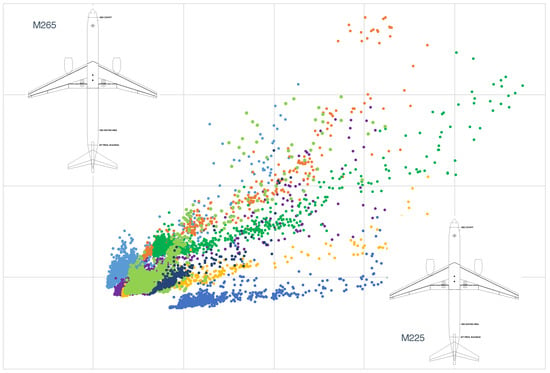
The airplane assumed in the sample problem was a medium-size, single-aisle subsonic civil passenger transport developed typically for transatlantic flights. The wing, tail, and fuselage were assumed to be fabricated with composite materials. Two derivatives, constituting a family, with identical wing and tail geometries, were considered. The fuselage cross-section, engine installation points, and landing gear installation points of the two airplanes were also identical. The two types of airplanes were named M225 and M265 in this study, and the performance specifications are presented in Table 3. In this study, a multiobjective optimization was performed to minimize the block fuel weight of the design mission for each type of airplane (M225 and M265).
3.2. Optimization Method
Various optimization methods have been proposed for airplane conceptual design [4,31,32,33,34]. In this study, an EA was used to solve the sample problem. EAs are heuristic optimization methods that emulate the evolutionary strategy of species in nature to improve solutions [35]. As a set of design parameters characterize an airplane, the set is considered a “gene” of the airplane. EAs are robust; therefore, they are suitable for solving problems that require simultaneously optimizing many design parameters, such as airplane conceptual design optimization problems. The schematic of the design parameter optimization process using an EA is shown in Figure 1. In the process, the proposal of the design parameters and their evaluation were repeatedly cycled.
3.2.1. Proposing Design Parameters
To propose desirable design parameters, a constrained multiobjective optimization code developed by Tohoku University, referred to as the constrained multiobjective genetic algorithm (CMOGA), was used. In the program code, Fonseca and Fleming’s multiobjective genetic algorithm (MOGA) [36] was used as the optimizer. The MOGA is a simple and robust EA that is capable of multiobjective optimization and has been widely used in various industrial sectors.
The constraint-handling technique (CHT) [37,38] is key when an EA is used for complex airplane conceptual design optimization problems, because feasible solutions exist in a region with a limited extent, restricted by many contradicting constraints. Efficiency in addition to robustness is required to search for and find the desired feasible solutions within a limited product-development timeframe. In the CMOGA, the more less-violations method (MLVM) [39] is used as the CHT. The MLVM is an efficient and robust CHT developed by the authors for EAs. The CHT uses a strategy to preserve diverse solutions in a region next to the feasible region, referred to as the acceptable region, to improve the level of optimization of the feasible solutions. Its search bias toward the feasible region is relatively strong; therefore, it is suitable for solving optimization problems with many constraints, such as airplane conceptual design optimization problems. The MLVM module (written in Fortran) is available online [40].
In the sample problem, a total of 25 design parameters (13 common-to-all-types design parameters and 6 × 2 dedicated-to-a-type design parameters for M225 and M265) and 152 constraints (76 × 2 constraints for M225 and M265) were considered.
3.2.2. Evaluating Design Parameters
To evaluate the design parameters proposed by the optimization code CMOGA, an airplane sizing computer code developed by Mitsubishi Heavy Industries, Ltd., Tokyo, Japan, referred to as the transport-category airplane design program (TCAD), was used. TCAD reads the design parameters and estimates various properties of the airplane, such as the geometry, mass properties, aerodynamics, engine performance (including thermodynamic cycle properties), mission and field performances, stability and control characteristics, and environmental compatibility. Typical values for commercial transport airplanes were assumed for the necessary inputs to TCAD, such as the chordwise spar locations of the aerodynamic surfaces, in addition to the design parameters.
The architecture of TCAD is similar to that of [41]. TCAD is comprised of multiple functional modules, with each module dedicated to a specific property of an airplane. The following is a brief explanation of the methods used in each functional module.
In the aerodynamics module, the aerodynamic forces and moments, including the control surface effectiveness and dynamic stability derivatives, are estimated with a vortex lattice method (VLM) [42]. Then, the zero-lift drags, such as the friction drag and profile drag [43,44], and nonlinear effects, such as the flow separation effect [43], are added. In the mass property module, the airframe component masses are estimated with empirical formulae, similar to [45], developed indigenously with statistical analyses on the airframe-component mass data. The CG and inertia properties assume a typical distribution of the airframe components for commercial transport airplanes. In the propulsion module, the uninstalled engine performance is estimated by an engine cycle analysis, similar to (but simpler than) [46]. The flat rating is considered. Then, the installed drags [47,48] are added for the installed engine performance. The result of the engine cycle analysis is used to estimate the dimensions and masses of the engine components [49], selecting the most suitable material for each part based on its thermal environment. In the performance module, the mission and field performances are estimated by integrating the equation of the motion of the airplane, as in [3]. Trims in roll, pitch, and yaw are considered. In the stability and control module, the stability and control characteristics, such as the natural frequencies and damping ratios of the longitudinal and lateral-directional modes, are estimated from the linearized equations of the motion of the airplane [50,51,52]. In the airport noise module, the magnitudes of the airframe and engine noise sources (broadband noises and tones) [53,54,55,56] are estimated using the results of the engine cycle analysis, and then corrected for the propagation effects [57,58,59] using the takeoff and landing trajectories calculated by the performance module, and finally integrated into the EPNLs, as prescribed in [6].
3.3. Optimization Setup
The optimization was performed using the Affinity computer system of the Institute of Fluid Science at Tohoku University. Each node of Affinity was comprised of two 2.4 GHz CPUs (20 cores per CPU) with a 768 GB memory. A total of 64 cores were used for the sample problem. Each optimization cycle took approximately one minute and a single run took approximately two days. As EA uses a heuristic strategy to optimize solutions, eight independent runs were performed for robustness.
In the EA process, a population size of 32 was selected, simulating the limited parallel computing resources available in the designing rooms in the industry. Then, 64 evaluations (32 evaluations for each type of airplane) were performed in parallel in an optimization loop, which was cycled to 3000 generations. No parallelization in each evaluation was sought. Ranking was performed using Fonseca and Fleming’s procedure. A fitness formula was used with , and no fitness-sharing techniques were used. Stochastic selection was used with the best-N elitism. A blended crossover, with a probability of 1 and a distribution index of 0.5, and a polynomial mutation, with a probability of 0.05 and a distribution index of 5, were used. The MLVM acceptable region was inhibited until the first feasible solution emerged.
3.4. Results and Discussion
In this section, the optimization results of the sample problem are discussed. The distributions of the feasible solutions of the eight independent runs are shown in Figure 2. In contrast to the typical results of the unconstrained multiobjective optimizations wherein solutions form a Pareto front, no definite Pareto front was formed in each run. Instead, a “wedge-shape” front was formed in each run, and the set of the optimum solution(s) of each run (Runs 1, 4, 5, and 7) formed a Pareto front.
There were two groups of design parameters in this optimization problem; one was “common-to-all-types” and the other was “dedicated-to-a-type” (see Section 2.1.7). The common-to-all-types design parameters directly affect all objectives of the airplane family and are directly constrained by all constraints of the airplane family. The feasible solutions exist inside of a wedge-shape region with one edge constrained by the constraints of one type of the airplane family and the other edge constrained by the constraints of the other type of the airplane family; feasible solutions evolve toward a “corner” formed by these constraints, resulting in a “wedge-shape” front. The shape of the wedge depends on the tightness of the constraints. If the constraints are tight, no Pareto front may be allowed to form. If the constraints are loose, a small Pareto front may be allowed to form at the tip of the wedge. This mechanism is considered typical for constrained multiobjective optimization for commercial transport airplanes that constitute a family, wherein the feasible regions are limited by the contradicting constraints for multiple types of the airplane family.
On the other hand, the dedicated-to-a-type design parameters directly affect the related objective and indirectly affect the other objectives of the airplane family through the common-to-all-types design parameters; they are relatively tightly constrained by the related constraints but relatively loosely constrained by the other constraints of the airplane family. These features of the dedicated-to-a-type design parameters provide a potential to allow the conventional Pareto front formation.
To identify the mechanism of the Pareto front formation, the optimal solutions of all runs are summarized in Table 4. A trade-off between the TIT and wing aspect ratio was observed on the Pareto front formed by the optimal solutions of Runs 1, 4, 5, and 7. Although there were some nonlinearities in the trend of the design parameter values, the approximate mechanism of the Pareto front formation in the sample problem was considered as follows; (1) as the TIT of M225 (a dedicated-to-a-type design parameter) increased, the engine thrust increased. Furthermore, the increased TIT allowed the optimal OPR and BPR to increase, improving the fuel efficiency and decreasing the block fuel weight (the objective of M225) and the gross weight of the airplane accordingly. (2) the increased engine thrust and the decreased gross weight of M225 allowed a decrease in the optimal wing aspect ratio (a common-to-all-types design parameter) to comply with the field performance requirement for M225. (3) the decreased wing aspect increased the lift-dependent drag of M265, increasing the fuel consumption and eventually the block fuel weight (the objective of M265).
Thus, the dedicated-to-a-type design parameters directly affected the related objective but also indirectly affected the other objectives of the airplane family through the common-to-all-types design parameters, allowing a Pareto front to form. The mechanism was complex, as many factors were interrelated. Further investigation is needed in the future on the complex behavior of the solutions of the constrained multiobjective optimization problems for commercial transport airplanes.
In Runs 2 and 3 (also in Runs 6 and 8, marginally), the solutions converged prematurely to local optimums, as shown in Figure 2. Since EA uses a heuristic strategy to improve solutions, the optimization results may vary depending on various factors, such as where in the design space the initial solutions are distributed and where in the feasible region the first feasible solution lands. In this study, the number of populations was set to 32 to simulate the limited parallel computing resources in the actual designing rooms in the industry, which was considered relatively small for the number of the design parameters (25). As the number of populations was insufficient for the number of design parameters, it tended to cause a premature convergence, because the randomly generated initial individuals were not distributed widely enough in the design parameter space.
The optimization methods need to have the capability to search for and find the global optimum(s) robustly and efficiently without premature convergence even in a limited computational resource environment. The formulation presented in this paper provides a baseline to facilitate research on developing robust and efficient optimization methods for complex optimization problems, including the conceptual design optimization problems for commercial transport airplanes.
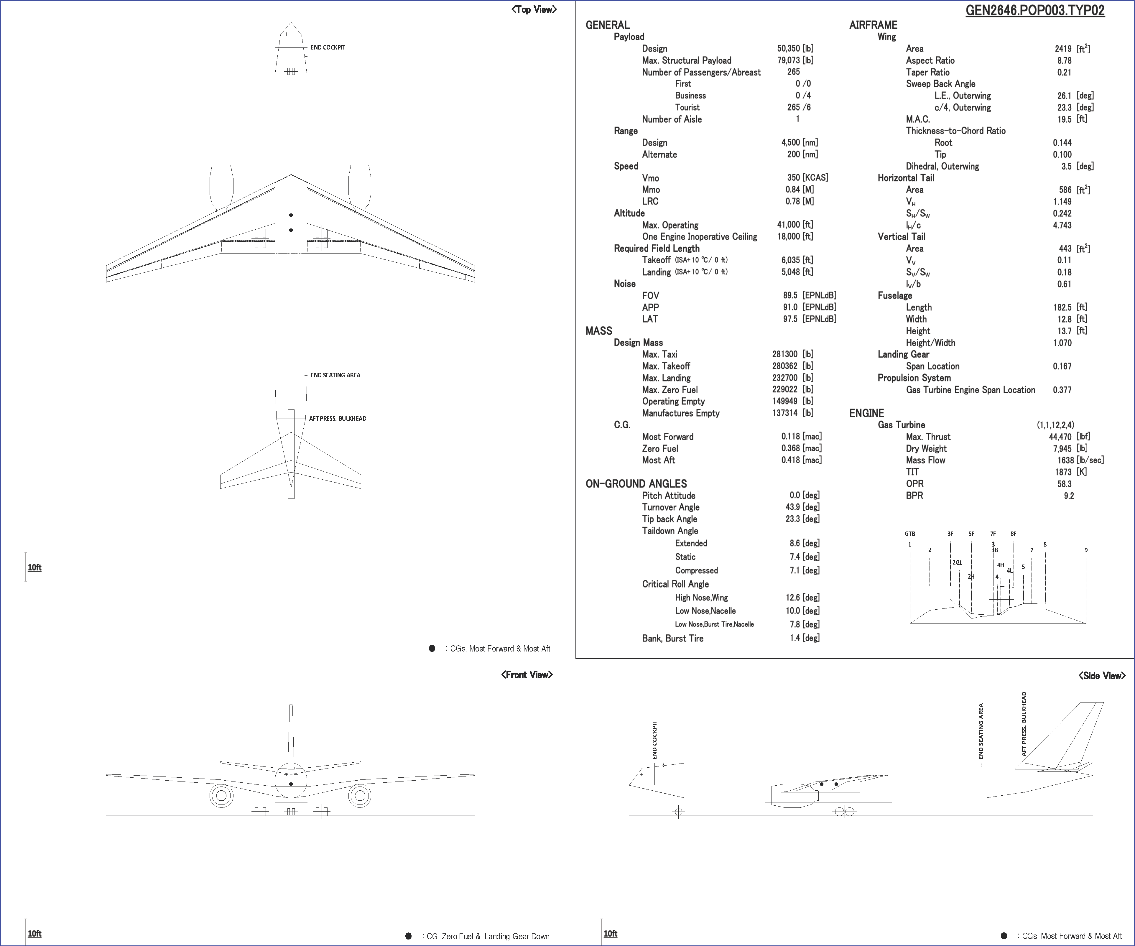
In Table 4, the optimal (or selected) solutions are compared with the existing airplane family Boeing 757 (B757) designed for performance specifications similar to those used in this study. The B757 family is constituted with two derivatives with identical wing and tail geometries but different performance specifications. In the airplane family, B757-200 and B757-300 correspond to M225 and M265, respectively. Reasonably similar results were obtained, with the caveat that it was not an exact comparison, as some of the performance specifications, such as the entry-into-service year (or technology level), were not identical. Furthermore, note that the geometrical parameter values of B757s were measured from the drawings in the public material [23], which may not be accurate. As an example, three-view drawings of M225 and M265 of the selected solution of Run 7 are shown in Figure 3.
The optimization results of the sample problem indicated that realistic conceptual design optimization of commercial transport airplanes, including simultaneous optimization of family airplanes, could be performed with the proposed formulation.
In this study, the scope of airplane configuration was limited to the conventional tube-and-wing configuration with a low wing, tail surfaces, and wing-mounted engines and main landing gear. This scope covers most of today’s commercial transport airplanes. However, the configurations of commercial transport airplanes do not and will not necessarily fall within this scope.
Small commercial transport airplanes often adopt other configurations, such as high-wing configuration and aft-mounted engine configuration. In such cases, modifications to the design parameters and constraints in this formulation are necessary, especially to those for the engine installation and main landing gear installation. Modifications to the regression formulae used in the airplane sizing program may also be necessary. With such modifications, this formulation is applicable to such small commercial transport airplanes.
This discussion may apply to the commercial transport airplanes in innovative configurations, such as blended wing-body airplane [60] and turboelectric airplane [61]. Additional design parameters and constraints may need to be defined, especially for the fuselage and propulsion system. Modification to the regression formulae used in the airplane sizing program may require additional challenges, such as preliminary structure design. With additional modifications to the design parameters and constraints and also to the regression formulae, this formulation is considered to be applicable to such innovative airplanes.
As the computing power increases, functional modules of an airplane evaluation software (see Figure 1) will be progressively replaced with increasingly sophisticated analyzers, such as aerodynamic analyzers using computational fluid dynamics (CFD) and structural analyzers using finite element analysis (FEA), which will eventually realize a highly-capable airplane conceptual design optimizer in the future. Coupled with the formulation presented in this paper, with proper modifications, the optimizer would provide a highly-precise and highly-reliable conceptual designing optimization for future commercial transport airplanes.
4. Conclusions
A realistic conceptual design optimization problem for commercial transport airplanes was formulated with reasonable fidelity and comprehensiveness by selecting appropriate design parameters, constraints, and objectives, aiming to provide a baseline to facilitate research on developing robust and efficient optimization methods for the conceptual design of commercial transport airplanes.
As a sample problem, a multiobjective simultaneous optimization of the design parameters for two types of civil passenger transport airplanes that constitute a family, with identical wing and tail geometries but different performance specifications, was performed using an EA: the MOGA coupled with the MLVM. Eight independent runs were performed for robustness.
In contrast to the typical results of unconstrained multiobjective optimizations wherein solutions formed a Pareto front, no definite Pareto front was formed in each run. Instead, a wedge-shape front was formed in each run, and the set of the optimum solution(s) of each run formed a Pareto front. An investigation into the Pareto solutions identified that the design parameters dedicated to a type of the airplane family allowed the Pareto front to form by directly affecting the related objective but also indirectly affecting the other objective of the airplane family through the design parameters common to all types of the airplane family. In some of the eight runs, the solutions converged prematurely to local optimums in an environment that simulated the limited computational resources available in the designing rooms in the industry.
The optimization results indicated that realistic conceptual design optimization of commercial transport airplanes, including simultaneous optimization of family airplanes, could be performed with the proposed formulation.
Author Contributions
Conceptualization, H.T. and S.O.; methodology, H.T.; software, H.T.; validation, H.T.; formal analysis, H.T.; investigation, H.T.; resources, S.O.; data curation, H.T.; writing—original draft preparation, H.T.; writing—review and editing, S.O.; visualization, H.T.; supervision, S.O. All authors have read and agreed to the published version of the manuscript.
Funding
This research received no external funding.
Institutional Review Board Statement
Not applicable.
Informed Consent Statement
Not applicable.
Data Availability Statement
The data presented in this study are available on request from the corresponding author. The data are not publicly available due to the Software Use Contract between Mitsubishi Heavy Industries, Ltd. and Tohoku University. The figures presented in this paper are available in FigShare at doi:10.6084/m9.figshare.20331327.
Acknowledgments
The authors would like to thank Mitsubishi Heavy Industries, Ltd., for allowing us to use the computer code TCAD and to publish this paper.
Conflicts of Interest
The authors declare no conflict of interest.
Abbreviations
The following abbreviations are used in this manuscript:
| BPR | Bypass ratio |
| CAP | Control anticipation parameter |
| CFD | Computational fluid dynamics |
| CG | Center of gravity |
| CHT | Constraint-handling technique |
| CMOGA | Constrained multiobjective genetic algorithm |
| EA | Evolutionary algorithm |
| EPNL | Effective perceived noise level |
| FAR | Federal Aviation Regulations |
| FEA | Finite Element Analysis |
| FOD | Foreign object damage |
| MLVM | More less-violations method |
| MOGA | Multiobjective genetic algorithm |
| OPR | Overall pressure ratio |
| TCAD | Transport-category airplane design program |
| TIT | Turbine inlet temperature |
| VLM | Vortex lattice method |
| V | Takeoff decision speed |
| V | Takeoff safety speed |
| V | Engine failure speed |
| V | Final takeoff speed |
| V | Liftoff speed |
| V | Minimum control speed, in the air |
| V | Minimum control speed, in the landing configuration |
| V | Minimum control speed, on the ground |
| V | Minimum unstick speed |
| V | Rotation speed |
| V | Landing reference speed |
| V | Stall speed, reference |
| Time to achieve 30 degrees bank angle change | |
| Undamped natural frequency, Dutch roll | |
| Undamped natural frequency, short-period response | |
| Damping ratio, Dutch roll | |
| Damping ratio, short-period response |
References
- Roskam, J. Airplane Design, 1st ed.; DARcorporation: Lawrence, KS, USA, 1985; Volumes 1–8. [Google Scholar]
- Raymer, D. Aircraft Design: A Conceptual Approach, 1st ed.; AIAA Education Series (AIAA): Washington, DC, USA, 1989; Available online: https://perma.cc/U478-X52U (accessed on 22 August 2022).
- Jenkinson, L.; Simpkin, P.; Rhodes, D. Civil Jet Aircraft Design, 1st ed.; AIAA Education Series; AIAA: Washington, DC, USA, 1999. [Google Scholar]
- Torenbeek, E. Advanced Aircraft Design: Conceptual Design, Analysis and Optimization of Subsonic Civil Airplanes; Aerospace Series; John Wiley & Sons: Hoboken, NJ, USA, 2013. [Google Scholar]
- U.S. Government Publishing Office. Title 14 Code of Federal Regulations. 2021. Available online: https://www.ecfr.gov/current/\title-14 (accessed on 22 August 2022).
- ICAO Annex 16 to the Convention on International Civil Aviation. In Environmental Protection—Volume I—Aircraft Noise, 8th ed.; July 2017; Available online: https://digitallibrary.un.org/record/421894 (accessed on 22 August 2022).
- Sobieski, J.; Haftka, R. Multidisciplinary aerospace design optimization: Survey of recent developments. In Proceedings of the 34th Aerospace Science Meeting and Exhibit (AIAA 96-0711), Reno, NV, USA, 15–18 January 1995. [Google Scholar] [CrossRef]
- Kroo, I. An interactive system for aircraft design and optimization. In Proceedings of the Aerospace Design Conference (AIAA 92–1190), Irvine, CA, USA, 3–6 February 1992. [Google Scholar] [CrossRef]
- Crispin, Y. Aircraft conceptual optimization using simulated evolution. In Proceedings of the 32nd Aerospace Sciences Meeting and Exhibit (AIAA 94–0092), Reno, NV, USA, 10–13 January 1994. [Google Scholar] [CrossRef]
- Gage, P. New Approaches to Optimization in Aerospace Conceptual Design; Technical Report NASA CR–196695; NASA: Washington, DC, USA, 1995. Available online: https://ntrs.nasa.gov/citations/19950018016 (accessed on 22 August 2022).
- Roth, G.; Crossley, W. Commercial transport aircraft conceptual design using a genetic algorithm based approach. In Proceedings of the 7th AIAA/USAF/NASA/ISSMO Symposium on Multidisciplinary Analysis and Optimization (AIAA 98–4934), St. Louis, MO, USA, 2–4 September 1998. [Google Scholar] [CrossRef]
- Perez, R.; Chung, J.; Behdinan, K. Aircraft conceptual design using genetic algorithms. In Proceedings of the 8th Symposium on Multidisciplinary Analysis and Optimization (AIAA–2000–4938), Long Beach, CA, USA, 6–8 September 2000. [Google Scholar] [CrossRef]
- Perez, R.; Behdinan, K. Effective multi-mission aircraft conceptual design optimization using a hybrid multi-objective evolutionary method. In Proceedings of the 9th AIAA/ISSMO Symposium on Multidisciplinary Analysis and Optimization (AIAA–2002–5464), Atlanta, GA, USA, 4–6 September 2002. [Google Scholar] [CrossRef]
- Cai, Y.; Rajaram, D.; Mavris, D.N. Simultaneous aircraft sizing and multi-objective optimization considering off-design mission performance during early design. Aerosp. Sci. Technol. 2022, 126, 107662. [Google Scholar] [CrossRef]
- Antonie, N.; Kroo, I. Framework for Aircraft Conceptual Design and Environmental Performance Studies. AIAA J. 2005, 43, 2100–2109. [Google Scholar] [CrossRef]
- Schwartz, E.; Kroo, I. Aircraft design: Trading cost and climate impact. In Proceedings of the 47th AIAA Aerospace Sciences Meeting Including The New Horizons Forum and Aerospace Exposition (AIAA 2009–1261), Orlando, FL, USA, 5–8 January 2009. [Google Scholar] [CrossRef]
- Henderson, R.; Martins, J.; Perez, R. Aircraft Conceptual Design for Optimal Environmental Performance. Aeronaut. J. 2012, 116, 1–22. [Google Scholar] [CrossRef] [Green Version]
- Karpuk, S.; Radespiel, R.; Elham, A. Assessment of Future Airframe and Propulsion Technologies on Sustainability of Next-Generation Mid-Range Aircraft. Aerospace 2022, 9, 279. [Google Scholar] [CrossRef]
- Saravanamuttoo, H.; Rogers, G.; Cohen, H.; Straznicky, P. Gas Turbine Theory, 6th ed.; Pearson Education Ltd.: London, UK, 2009. [Google Scholar]
- Royal Aeronautical Society. An Introduction to Aircraft Noise; ESDU 02020 Amendment B; Royal Aeronautical Society: London, UK, 2013. [Google Scholar]
- Currey, N. Aircraft Landing Gear Design: Principles and Practices, 1st ed.; AIAA Education Series; AIAA: Washington, DC, USA, 1988. [Google Scholar]
- Chai, S.; Mason, W. Landing Gear Integration in Aircraft Conceptual Design; Technical Report MAD 96-09-01; Virginia Polytechnic Institute and State University: Blacksburg, VA, USA, 1996. Available online: https://ntrs.nasa.gov/citations/19970031272 (accessed on 22 August 2022).
- Boeing. Airplane Characteristics for Airport Planning. Available online: https://www.boeing.com/commercial/airports/plan_manuals.page (accessed on 22 August 2022).
- Airbus. Aircraft Characteristics: Airport Operations & Tech Data—Airport and Maintenance Planning. Available online: https://www.airbus.com/en/airport-operations-and-technical-data/aircraft-characteristics (accessed on 22 August 2022).
- Nita, M.F. Contributions to Aircraft Preliminary Design and Optimization. Ph.D. Thesis, Politehnica University of Bucharest, Bucharest, Romania, 2012. Available online: https://perma.cc/SM5U-EPT9 (accessed on 22 August 2022).
- Scholz, D. Aircraft Design. Lecture Notes. 2015. Available online: http://HOOU.ProfScholz.de (accessed on 22 August 2022).
- US Department of Defence. Flying Qualities of Piloted Airplanes; MIL–F–8785C. 5 November 1980. Available online: https://perma.cc/FN56-6YAG (accessed on 22 August 2022).
- ICAO Annex 16 to the Convention on International Civil Aviation. In Environmental Protection—Volume III—Airplane CO2 Emissions, 1st ed.; July 2017; Available online: https://perma.cc/SQ74-DSP3 (accessed on 22 August 2022).
- Ritchie, H.; Roser, M.; Rosado, P. CO2 and Greenhouse Gas Emissions. Our World in Data. 2020. Available online: https://perma.cc/694W-FCMD (accessed on 22 August 2022).
- Air Transport Association of America. Standard Method of Estimating Comparative Direct Operating Costs of Turbine Powered Transport Airplanes; Air Transport Association of America: Washington, DC, USA, 1967; Available online: https://docplayer.net/39861253-Standard-method-of-estimating-comparative-direct-operating-costs-of-turbine-powered-transport-airplanes.html (accessed on 22 August 2022).
- Sliwa, S.; Arbuckle, P. OPDOT: A Computer Program for the Optimum Preliminary Design of A Transport Airplane; Technical Report NASA TM–81857; NASA: Washington, DC, USA, 1980. Available online: https://ntrs.nasa.gov/citations/19830002844 (accessed on 22 August 2022).
- Kroo, I.; Takai, M. A quasi-procedural, knowledge-based system for aircraft design. In Proceedings of the AIAA/AHS/ASEE Aircraft Design, Systems and Operating Meeting (AIAA–88–4428), Atlanta, GA, USA, 7–9 September 1988. [Google Scholar] [CrossRef]
- Jayaram, S.; Myklebust, A. ACSYNT—A Standards-based system for parametric computer aided conceptual design of aircraft. In Proceedings of the Aerospace Design Conference (AIAA 92–1268), Irvine, CA, USA, 3–6 February 1992. [Google Scholar] [CrossRef]
- Hoburg, W.; Abbeel, P. Geometric Programming for Aircraft Design Optimization. AIAA J. 2014, 52, 2414–2426. [Google Scholar] [CrossRef]
- Eiben, A.; Smith, J. Introduction to Evolutionary Computing, 2nd ed.; Natural Computing Series; Springer: Berlin/Heidelberg, Germany, 2015. [Google Scholar] [CrossRef]
- Fonseca, C.; Fleming, P. Genetic algorithms for multiobjective optimization: Formulation, discussion and generalization. In Proceedings of the Fifth International Conference, San Mateo, CA, USA, 13–15 July 1993; Available online: https://perma.cc/SL3J-EF6U (accessed on 22 August 2022).
- Coello, C. Theoretical and Numerical Constraint-Handling Techniques Used with Evolutionary Algorithms: A Survey of the State of the Art. Comput. Methods Appl. Mech. Eng. 2002, 191, 1245–1287. [Google Scholar] [CrossRef]
- Mezura-Montes, E.; Coello, C. Constraint-handling in nature-inspired numerical optimization: Past, present, and future. Swarm Evol. Comput. 2011, 1, 173–194. [Google Scholar] [CrossRef]
- Takami, H.; Obayashi, S. A Comparator-based Constraint Handling Technique for Evolutionary Algorithms. AIP Adv. 2022, 12, 055229. [Google Scholar] [CrossRef]
- Takami, H. MLVM—A Constraint-Handling Technique for Evolutionary Algorithms “More Less-Violations Method (MLVM)”. Available online: https://github.com/hikarutakami/MLVM (accessed on 22 August 2022).
- Smith, H.; Sziroczák, D.; Abbe, G.E.; Okonkwo, P. The GENUS aircraft conceptual design environment. Proc. Inst. Mech. Eng. Part G J. Aerosp. Eng. 2018, 233, 2932–2947. [Google Scholar] [CrossRef]
- Miranda, L.; Elliot, R.; Baker, W. A Generalized Vortex Lattice Method for Subsonic and Supersonic Flow Applications; Technical Report NASA CR-2865; NASA: Washington, DC, USA, 1977. Available online: https://ntrs.nasa.gov/citations/19800000236 (accessed on 22 August 2022).
- Fink, R. USAF Stability and Control DATCOM; Technical Report AFWAL-TR-83-3048; Flight Dynamics Laboratory, Air Force Wright Aeronautical Laboratories: Washington, DC, USA, 1978; Available online: https://perma.cc/LQ5Y-RE5K (accessed on 22 August 2022).
- Hoerner, S. Fluid-Dynamic Drag; Hoerner Fluid Dynamics: Bakersfield, CA, USA, 1965; Available online: https://n2t.net/ark:/13960/t57f0bk2j (accessed on 22 August 2022).
- Glatt, C. WAATS—A Computer Program for Weights Analysis of Advanced Transportation Systems; Technical Report NASA CR-2420; NASA: Washington, DC, USA, 1974. Available online: https://ntrs.nasa.gov/citations/19740027176 (accessed on 22 August 2022).
- Kurzke, J. GasTurb Details 6; GasTurb GmbH: Aachen, Germany, 2021; Available online: https://perma.cc/ZBM3-GX8Q (accessed on 22 August 2022).
- Seddon, J.; Goldsmith, E. Intake Aerodynamics, 1st ed.; AIAA Education Series; AIAA: New York, NY, USA, 1985. [Google Scholar]
- Covert, E. (Ed.) Thrust and Drag: Its Prediction and Verification, 1st ed.; Progress in Astronautics and Aeronautics; AIAA: New York, NY, USA, 1985; Volume 98. [Google Scholar] [CrossRef]
- Pera, R.; Onat, E.; Klees, G.; Tjonneland, E. A Method to Estimate Weight and Dimensions of Aircraft Gas Turbine Engines Volume I: Method of Analysis Final Report; Technical Report NASA CR-135170; NASA: Washington, DC, USA, 1977. Available online: https://ntrs.nasa.gov/citations/19770018227 (accessed on 22 August 2022).
- McLean, D. Automatic Flight Control Systems; Series in Systems and Control Engineering; Prentice Hall International: London, UK, 1990. [Google Scholar]
- Scholz, D. Corrected: McLean, D. Automatic Flight Control Systems; Series in Systems and Control Engineering. 2022. Available online: https://perma.cc/VPA5-JPP2 (accessed on 22 August 2022).
- Katayanagi, R. Stability and Control of Airplanes, 1st ed.; Morikita Publishing: Tokyo, Japan, 2007. (In Japanese) [Google Scholar]
- Zorumski, W. Aircraft Noise Prediction Program Theoretical Manual; Technical Report NASA TM-83199 Part 1; NASA: Washington, DC, USA, 1982. Available online: https://ntrs.nasa.gov/citations/19820012072 (accessed on 22 August 2022).
- Zorumski, W. Aircraft Noise Prediction Program Theoretical Manual; Technical Report NASA TM-83199 Part 2; NASA: Washington, DC, USA, 1982. Available online: https://ntrs.nasa.gov/citations/19820012073 (accessed on 22 August 2022).
- Stone, J.; Krejsa, E.; Clark, B. Enhanced Core Noise Modeling for Turbofan Engines; Technical Report NASA/CR-2011-217026; NASA: Washington, DC, USA, 2011. Available online: https://ntrs.nasa.gov/citations/20110013366 (accessed on 22 August 2022).
- Stone, J.; Krejsa, E.; Clark, B. Jet Noise Modeling for Suppressed and Unsuppressed Aircraft in Simulated Flight; Technical Report NASA/TM-2009-215524; NASA: Washington, DC, USA, 2009. Available online: https://ntrs.nasa.gov/citations/20090015381 (accessed on 22 August 2022).
- Royal Aeronautical Society. Evaluation of the Attenuation of Sound by an Uniform Atmosphere; ESDU 78002 Amendment D; Royal Aeronautical Society: London, UK, 2019; ISBN 978 0 85679 208 3. [Google Scholar]
- Royal Aeronautical Society. The Correction of Measured Noise Spectra for the Effects of Ground Reflection; ESDU 94035; Royal Aeronautical Society: London, UK, 2011; ISBN 978 0 85679 922 8. [Google Scholar]
- Royal Aeronautical Society. Estimation of Lateral Attenuation of Air-to-Ground Jet or Turbofan Aircraft Noise in One-Third Octave Bands; ESDU 82027; Royal Aeronautical Society: London, UK, 2011; ISBN 978 0 85679 408 7. [Google Scholar]
- Greitzer, E.; Bonnefoy, P.; delaRosaBlanco, E.; Dorbian, C.; Drela, M.; Hall, D.; Hansman, R.; Hileman, J.; Liebeck, R.; Lovegren, J.; et al. N+3 Aircraft Concept Designs and Trade Studies; Technical Report NASA/CR—2010-216794/VOL1; NASA: Washington, DC, USA, 2010; Volume 1. Available online: https://ntrs.nasa.gov/citations/20100042401 (accessed on 22 August 2022).
- Welstead, J.R.; Felder, J.L. Conceptual design of a single-aisle turboelectric commercial transport with fuselage boundary layer ingestion. In Proceedings of the 54th AIAA Aerospace Sciences Meeting, San Diego, CA, USA, 4–8 January 2016. [Google Scholar] [CrossRef] [Green Version]
Figure 1.
Design lParameter Optimization Process.
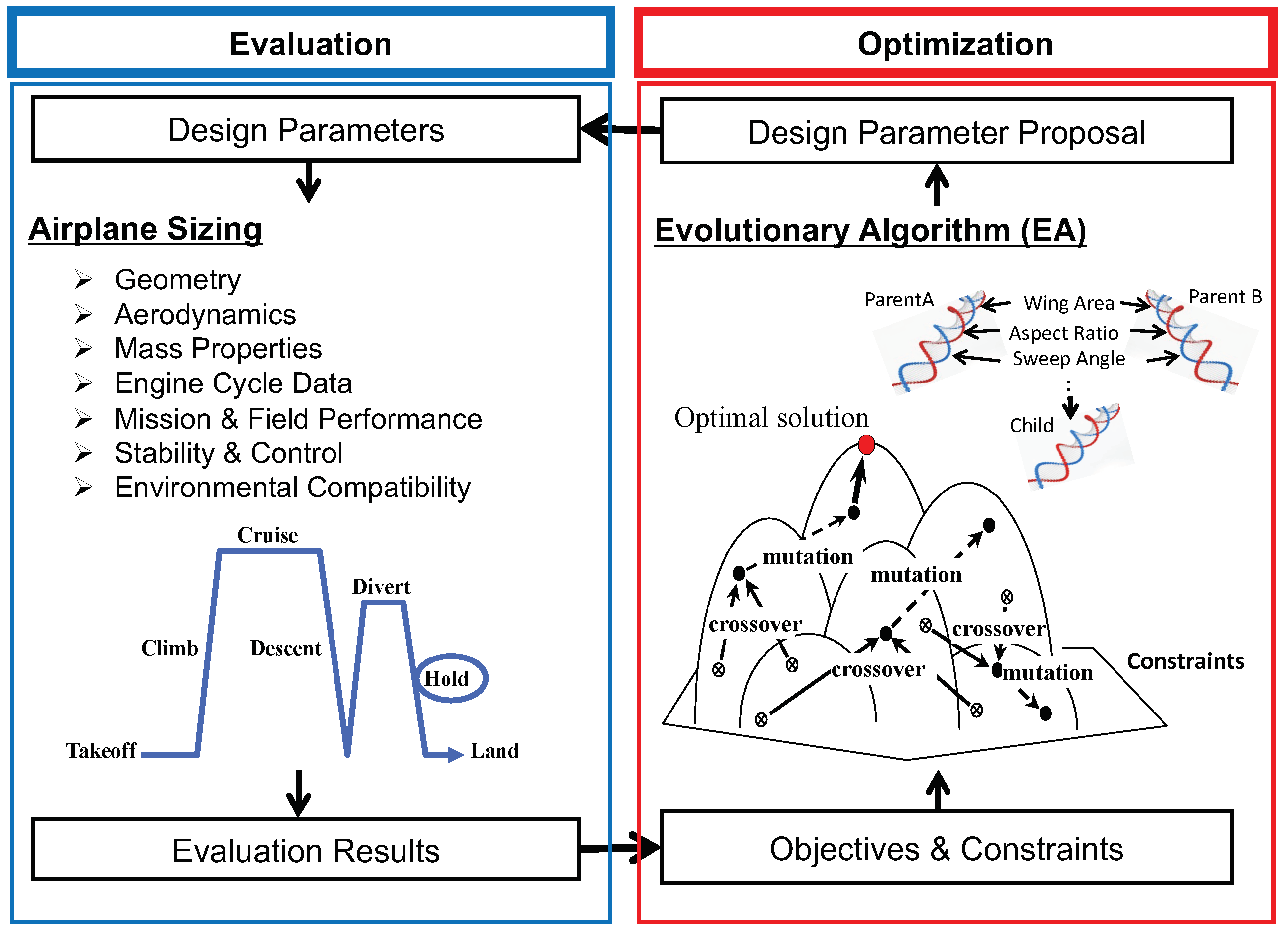
Figure 2.
Distribution of Feasible Solutions: Wide (Upper) and Close-up (Lower).

Figure 3.
Three-view drawings of M225 (upper) and M265 (lower), Run 7.


Table 1.
Design parameters.
| Parameter | Group 1 | Lower Bound | Upper Bound |
|---|---|---|---|
| Wing | |||
| Area (ft) | c | 2000 | 4000 |
| Aspect ratio | c | 5.0 | 15.0 |
| Sweepback angle, leading-edge (deg) | c | 20.0 | 40.0 |
| Spanwise boundary between aileron and flaps (fraction of semispan) | c | 0.7 | 0.8 |
| Thickness-to-chord ratio, theoretical root | c | 0.1 | 0.2 |
| Dihedral angle, inboard wing (deg) | c | 0.0 | 10.0 |
| Dihedral angle increment, outboard wing (deg) | c | −10.0 | 5.0 |
| Deflection angle, trailing-edge flap at takeoff (deg) | d | 1.0 | 20.0 |
| Deflection angle, trailing-edge flap at landing (deg) | d | 25.0 | 40.0 |
| Tail | |||
| Area ratio, vertical tail to wing | c | 0.05 | 0.35 |
| Area ratio, horizontal tail to wing | c | 0.05 | 0.35 |
| Engine | |||
| Thrust (lbf) | d | 25,000 | 55,000 |
| Turbine inlet temperature (℃) | d | 1400 | 1600 |
| Overall pressure ratio | d | 20.0 | 70.0 |
| Bypass ratio | d | 5.0 | 15.0 |
| Spanwise location (fraction of wing semispan) | c | 0.2 | 0.4 |
| Main Landing gear | |||
| Spanwise location (fraction between fuselage centerline and engine station) | c | 0.0 | 1.0 |
| Chordwise location (fraction between rear spar and landing gear beam) | c | 0.0 | 1.0 |
| Center of gravity | |||
| The most aft CG, with respect to mean aerodynamic chord | c | 0.25 | 0.50 |
1 “c” for common-to-all-types, “d” for dedicated-to-a-type.
Table 2.
Constraints.
| Constraint 1,2 | Requirement |
|---|---|
| Wing (1) | |
| Fuel tank volume | ≥Fuel volume |
| Engine (3) | |
| Compressor discharge height | ≥0.5 (inch) |
| Angle, nose landing gear to the most inboard point of engine inlet | ≥25.0 (deg) |
| Ground clearance, the lowest point of engine inlet | ≥0.5 × engine inlet diameter |
| Landing gear (8) | |
| Distance between trunnion and main landing gear | ≥0.33 × main landing gear length |
| Local wing thickness at main landing gear installation | ≥1.5 × main landing gear strut diameter |
| Main landing gear bogie accommodation | No interference with carry-through structure |
| Tipback angle | ≥Tail down angle |
| Turnover angle | ≤45.0 (deg) |
| Roll boundary on the ground, static | ≥10.0 (deg) |
| Roll boundary on the ground, tail-down attitude | ≥12.0 (deg) |
| Static load fraction, nose landing gear | ≥0.05 |
| Cruise performance (2) | |
| Long range cruise Mach number | ≥Specified long range cruise Mach number |
| Ceiling, one engine inoperative | ≥Specified ceiling |
| Field performance (17) | |
| FAR takeoff field length | ≤Specified takeoff field length |
| FAR landing field length | ≤Specified landing field length |
| FAR climb gradients 3 | As per FAR |
| FAR speed relations 4 | As per FAR |
| Stability and Control (41) | |
| Related to FAR (15) | |
| FAR maneuvers [V, V + XX, V, V] | within 75 percent of control surface authorities 9 |
| Elevator capability [V, V] | within 75 percent of elevator authority |
| Elevator capability, nose-down angular acceleration at stall | ≥0.1 (rad/s) |
| Rudder capability [V, V, V] | Trimmable |
| Rudder capability, crosswind landing | Trimmable for specified crosswind |
| Related to MIL (26) | |
| Longitudinal short-period response 5 | MIL-F-8785C Level 1 |
| Lateral-directional oscillation (Dutch roll) 6 | MIL-F-8785C Level 1 |
| Roll performance 7 | MIL-F-8785C Level 1 |
| Environmental Compatibility (4) | |
| Airport noise 8 | As per Annex 16 Volume I Chapter 14 |
1 Conditions are bracketed “[ ]” when constrained in multiple conditions. 2 Number of constraints is shown in bold parentheses “( )”. 3 For takeoff: Minimum climb gradients for the 1st segment at VLOF, 2nd segment at V2, and final segment at VFTO. For landing: Minimum climb gradient for go-around at VREF. 4 For takeoff: VMC ≥ 1.13 VSR, VEF ≥ VMCG, VR ≥ 1.05 VMC, VR ≥ V1, VLOF ≥ 1.05 VMU,V2 ≥ 1.1 VMC, V2 ≥ 1.13 VSR, VFTO ≥ 1.18 VSR. For landing: VREF ≥ 1.23 VSR, VREF ≥ VMCL, VSR (go-around) ≥ 1.1 VSR (landing). 5 Category B: Min/max ζSP (=0.3/2.0) and min/max CAPs (=0.085/3.6) for clean configuration. Category C: Min/max ζSP (=0.35/1.3), min/max CAPs (=0.16/3.6), and min ωnSP (=0.7) for takeoff and landing configurations. 6 Category B: Min ζd (=0.08), min ωnd (=0.4), and min ζd·ζnd (=0.15) for clean configuration. Category C: Min ζd (=0.08), min ζnd (=0.4), and min ζd·ζnd (=0.1) for takeoff and landing configurations. 7 Category B: Max t30 (=2.3 s) for clean configuration. Category C: Max t30 (=2.5 s) for takeoff and landing configurations. 8 Lateral noise, flyover noise, approach noise, and sum of margins of the 3 noises. 9 Initial trim at 1G with horizontal stabilizer; subsequent trim at elevated G with elevator.
Table 3.
Performance Specifications.
| Specification | M225 | M265 |
|---|---|---|
| Entry into service year (technology level) | 2030 | 2030 |
| Number of passengers (all economy) | 225 | 265 |
| Long range cruise Mach number | 0.78 | 0.78 |
| Design range | 4500 (nm) | 4500 (nm) |
| FAR takeoff field length | 7000 (ft) | 8000 (ft) |
| FAR landing field length | 5000 (ft) | 5500 (ft) |
| Max. crosswind for landing | 30 (kt) | 30 (kt) |
| Operational flight envelope | 41,000 (ft)/0.84 (Mach)/350 (kt) | 41,000 (ft)/0.84 (Mach)/350 (kt) |
| Ceiling with one engine inoperative | 18,000 (ft) | 18,000 (ft) |
Table 4.
Optimal (selected) solutions, with B757.
| Item | Group 1 | Run 1 | Run 2 | Run 3 | Run 4 | Run 5 | Run 6 | Run 7 | Run 8 | B757 2 |
|---|---|---|---|---|---|---|---|---|---|---|
| General | ||||||||||
| Entry into service year (technology level) | 2030 | 2030 | 2030 | 2030 | 2030 | 2030 | 2030 | 2030 | 1983 | |
| Gross weight, takeoff (lb), M225 | 253,848 | 254,142 | 256,073 | 251,068 | 248,000 | 256,831 | 250,604 | 253,346 | 255,000 | |
| Gross weight, takeoff (lb), M265 | 278,468 | 282,924 | 284,661 | 278,696 | 277,774 | 282,758 | 280,362 | 280,941 | 270,000 | |
| Block fuel weight (lb), M225 | 69,274 | 67,808 | 68,357 | 66,653 | 65,889 | 68,155 | 66,203 | 66,867 | - | |
| Block fuel weight (lb), M265 | 73,314 | 75,998 | 76,185 | 73,951 | 74,407 | 74,061 | 74,076 | 74,076 | - | |
| Wing loading (lb/ft), M225 | 105.3 | 107.9 | 107.5 | 104.2 | 105.7 | 104.6 | 103.6 | 102.2 | 125.1 | |
| Wing loading (lb/ft), M265 | 115.5 | 120.1 | 119.6 | 115.7 | 118.4 | 115.2 | 115.9 | 113.4 | 132.5 | |
| Thrust-to-weight ratio, M225 | 0.309 | 0.321 | 0.322 | 0.318 | 0.321 | 0.323 | 0.320 | 0.320 | 0.294 | |
| Thrust-to-weight ratio, M265 | 0.312 | 0.315 | 0.315 | 0.309 | 0.313 | 0.319 | 0.317 | 0.313 | 0.303 | |
| Wing | ||||||||||
| Area (ft) | c | 2410 | 2356 | 2381 | 2409 | 2346 | 2455 | 2419 | 2478 | 2038 |
| Aspect ratio | c | 8.88 | 9.13 | 9.18 | 8.97 | 8.65 | 8.93 | 8.78 | 8.71 | 7.65 |
| Sweepback angle, leading-edge (deg) | c | 26.1 | 26.9 | 26.9 | 26.1 | 26.2 | 26.1 | 26.1 | 25.9 | 28.4 |
| Spanwise boundary between aileron and flaps (fraction of semispan) | c | 0.731 | 0.700 | 0.700 | 0.701 | 0.748 | 0.700 | 0.700 | 0.730 | 0.764 |
| Thickness-to-chord ratio, theoretical root | c | 0.143 | 0.147 | 0.148 | 0.145 | 0.142 | 0.147 | 0.144 | 0.143 | 0.148 |
| Dihedral angle, inboard wing (deg) | c | 10.0 | 10.0 | 10.0 | 10.0 | 10.0 | 10.0 | 10.0 | 10.0 | 6.8 |
| Dihedral angle increment, outboard wing (deg) | c | −5.6 | −2.0 | −2.8 | −6.3 | −6.2 | −3.6 | −6.5 | −6.7 | −2.3 |
| Deflection angle, trailing-edge flap at takeoff (deg), M225 | d | 20.0 | 20.0 | 20.0 | 7.4 | 7.4 | 6.6 | 6.4 | 20.0 | 5.0 |
| Deflection angle, trailing-edge flap at takeoff (deg), M265 | d | 16.0 | 14.0 | 14.5 | 13.5 | 12.1 | 20.0 | 20.0 | 17.1 | 15.0 |
| Deflection angle, trailing-edge flap at landing (deg), M225 | d | 25.0 | 25.0 | 25.0 | 39.8 | 25.0 | 34.6 | 25.5 | 25.0 | 30.0 |
| Deflection angle, trailing-edge flap at landing (deg), M265 | d | 25.3 | 27.8 | 30.2 | 25.7 | 25.0 | 25.2 | 25.0 | 25.0 | 30.0 |
| Tail | ||||||||||
| Area ratio, vertical tail to wing | c | 0.186 | 0.194 | 0.195 | 0.184 | 0.184 | 0.183 | 0.183 | 0.182 | 0.174 |
| Area ratio, horizontal tail to wing | c | 0.236 | 0.300 | 0.301 | 0.249 | 0.245 | 0.245 | 0.242 | 0.247 | 0.272 |
| Engine | ||||||||||
| Thrust (lbf), M225 | d | 39,161 | 40,829 | 41,201 | 39,909 | 39,752 | 41,447 | 40,067 | 40,500 | 37,530 |
| Thrust (lbf), M265 | d | 43,468 | 44,499 | 44,840 | 43,006 | 43,444 | 45,125 | 44,470 | 43,957 | 40,900 |
| Turbine inlet temperature (℃), M225 | d | 1499 | 1550 | 1566 | 1532 | 1600 | 1507 | 1579 | 1562 | - |
| Turbine inlet temperature (℃), M265 | d | 1600 | 1600 | 1600 | 1600 | 1600 | 1600 | 1600 | 1600 | - |
| Overall pressure ratio, M225 | d | 41.1 | 54.5 | 51.2 | 54.8 | 51.4 | 50.1 | 52.9 | 52.7 | 26.7 |
| Overall pressure ratio, M265 | d | 57.8 | 59.7 | 59.3 | 58.0 | 58.7 | 58.1 | 58.3 | 58.2 | 29.4 |
| Bypass ratio, M225 | d | 9.3 | 9.4 | 9.9 | 9.0 | 10.0 | 10.0 | 9.7 | 10.0 | 5.7 |
| Bypass ratio, M265 | d | 9.0 | 8,4 | 8.6 | 8.5 | 8.4 | 9.6 | 9.2 | 9.0 | 5.5 |
| Spanwise location (fraction of wing semispan) | c | 0.380 | 0.363 | 0.372 | 0.372 | 0.388 | 0377 | 0.376 | 0.377 | 0.340 |
| Main Landing gear | ||||||||||
| Spanwise location (fraction between fuselage centerline and engine station) | c | 0.431 | 0.452 | 0.455 | 0.435 | 0.430 | 0.443 | 0.442 | 0.439 | 0.565 |
| Chordwise location (fraction between rear spar and landing gear beam) | c | 0.868 | 0.852 | 0.842 | 0.881 | 0.850 | 0.888 | 0.876 | 0.889 | 0.714 |
| Center of gravity | ||||||||||
| The most aft CG, with respect to mean aerodynamic chord | c | 0.414 | 0.381 | 0.386 | 0.407 | 0.421 | 0.417 | 0.418 | 0.426 | 0.380 |
1 “c” for common-to-all-types, “d” for dedicated-to-a-type. 2 “-” for unavailable.
Publisher’s Note: MDPI stays neutral with regard to jurisdictional claims in published maps and institutional affiliations. |
© 2022 by the authors. Licensee MDPI, Basel, Switzerland. This article is an open access article distributed under the terms and conditions of the Creative Commons Attribution (CC BY) license (https://creativecommons.org/licenses/by/4.0/).
Share and Cite
MDPI and ACS Style
Takami, H.; Obayashi, S. A Formulation of the Industrial Conceptual Design Optimization Problem for Commercial Transport Airplanes. Aerospace 2022, 9, 487. https://doi.org/10.3390/aerospace9090487
AMA Style
Takami H, Obayashi S. A Formulation of the Industrial Conceptual Design Optimization Problem for Commercial Transport Airplanes. Aerospace. 2022; 9(9):487. https://doi.org/10.3390/aerospace9090487
Chicago/Turabian StyleTakami, Hikaru, and Shigeru Obayashi. 2022. "A Formulation of the Industrial Conceptual Design Optimization Problem for Commercial Transport Airplanes" Aerospace 9, no. 9: 487. https://doi.org/10.3390/aerospace9090487
Note that from the first issue of 2016, this journal uses article numbers instead of page numbers. See further details here.