Taxonomy of Gas Turbine Blade Defects


Department of Mechanical Engineering, University of Canterbury, Christchurch 8041, New Zealand
*
Author to whom correspondence should be addressed.
Aerospace 2019, 6(5), 58; https://doi.org/10.3390/aerospace6050058
Submission received: 4 April 2019
/
Revised: 27 April 2019
/
Accepted: 17 May 2019
/
Published: 21 May 2019
(This article belongs to the Special Issue Managing Data and Information of Aerospace Product Lifecycle)
Abstract
:Context—The maintenance of aero engines is intricate, time-consuming, costly and has significant functional and safety implications. Engine blades and vanes are the most rejected parts during engine maintenance. Consequently, there is an ongoing need for more effective and efficient inspection processes. Purpose—This paper defines engine blade defects, assigns root-causes, shows causal links and cascade effects and provides a taxonomy system. Approach—Defect types were identified from the literature and maintenance manuals, categorisations were devised and an ontology was created. Results—Defect was categorised into Surface Damage, Wear, Material Separation and Material Deformation. A second categorisation identified potential causes of Impact, Environmental causes, Operational causes, Poor maintenance, Poor manufacturing and Fatigue. These two categorisations were integrated with an ontology. Originality—The work provides a single comprehensive illustrated list of engine blade defects, and a standardised defect terminology, which currently does not exist in the aviation industry. It proposes a taxonomy for both engine blade defects and root-causes, and shows that these may be related using an ontology.
Keywords:
aero engine; blade defects; blade failure; gas turbine; NDI; NDT; MRO; ontology; visual inspection
1. Introduction
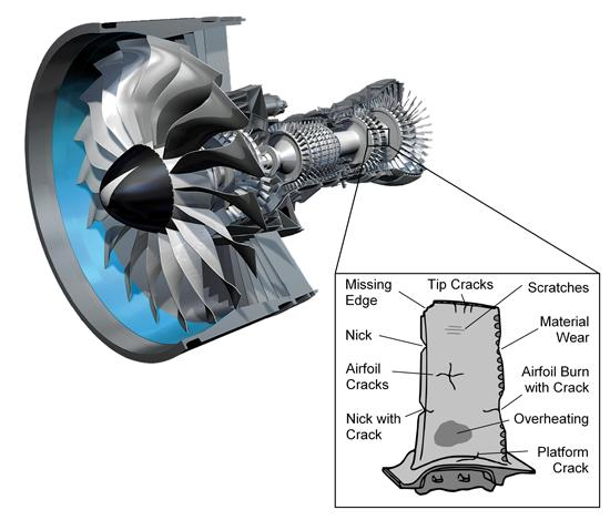
The operation of modern gas turbines demands ever higher temperatures, pressures and rotational speeds to increase power and improve efficiency [1]. This ultimately creates a strenuous environment for engine parts, particularly engine blades. Those blades are subject to high stress resulting from exposure to extreme operating conditions, such as high centrifugal loads, high temperatures, high pressures and vibration [2,3,4,5]. Blade failure and severe damage to the engine and airframe can be caused by each of those factors, and can even result in death of passengers [6]. Most recently, a Southwest Airline flight ended in a fatal accident, when a broken fan blade initiated a series of events that caused failure of the left engine and ultimately led to the death of a passenger [7].
To prevent such aircraft accidents or incidents, engine maintenance is essential. This is crucial for securing aircraft availability and passenger safety. Engine maintenance is provided by maintenance, repair and overhaul (MRO) service facilities. They typically apply a reliability-centred maintenance (RCM) methodology, whereby they seek to identify and manage failures to preserve the technical functionality, and hence safety and airworthiness of the engine. Most defects that can lead to failures are detected during maintenance inspection before any negative effects appear on flight operations. Early failure detection ensures low engine failure rates during flight operation [2,8]. The maintenance inspection is primarily by visual means [9,10,11]. The most rejected engine parts are blades and vanes from compressor and turbine sections [8]. During engine maintenance, the first step of the inspection process comprises that all blades are visually inspected for defects or indications of damages. Borescopes are the most important optical aid to visually inspect the inside of the engine, which is otherwise inaccessible. It can be performed in-situ on-wing or at the MRO facility, followed by complete disassembly of the engine module and on-bench piece part inspection, if any indication for a surface defects or structural damage was found during the borescope inspection [12].
The inspector has to examine the blades and identify surface discontinuities, deviations or anomalies, and quantify their intensity. In order to make a final decision on whether a part is serviceable, repairable or has to be replaced, subsequent inspection steps are often required and comprises other non-destructive testing (NDT) or inspection (NDI) methods. For example, infrared thermography, magnetic particle, eddy current, ultrasonic, radiographic and penetrant inspection are used to supplement visual inspection and to support detecting any subsurface flaws (e.g., inclusions, micro cracks, etc.) that cannot be detected by pure visual means. Nonetheless, visual inspection comprises the bulk of the defect-detection and initial quality inspections for engine repair.
After engine problems, such as compressor surge, unusual vibration or loss of performance, visual borescope inspection is performed to determine whether the engine is to be dismantled from the wing and sent to an MRO shop for more detailed inspection. Further, the findings of the induction borescope inspection at the MRO shop determines whether or not to commit to a costly disassembly of the engine. The maintenance of aero engines is intricate and time-consuming and even one maintenance episode (shop visit) may be an appreciable proportion of the engine list price [10,13]. Consequently, there is an ongoing need for more effective and efficient inspection processes.
Engine blades and vanes are the most expensive and highly stressed parts, and thus the most rejected parts during engine maintenance [8]. Engine vanes are similar to blades to the extent that both have an airfoil design and are made out of similar materials and coatings [8]. Thus, the defects found on engine vanes are identical to those on blades. For simplification, hereinafter the term ‘blade’ is used for both blades in the compressor and turbine section, and for turbine vanes.
The specific area under examination in this paper is the visual inspection of engine blades and vanes. This paper focuses on defining engine blade defects, highlighting the differences between them and providing a taxonomy system. Moreover, it proposes a method to link potential causes to the defects, and show the inter-relationships and cascade effects. The main audience to whom the work is directed are MRO service providers, but the results may also be applicable to engine developers and accident investigators.
2. Background Literature
2.1. Defect Perspectives
In the aircraft maintenance discipline, the term ‘defect’ is used to represent a component failure mode, which arises either from an intrinsic defect or an external event, and which becomes evident over time.
Different people have different definitions of engine blade defects. For instance, a pilot would describe a blade as defective when it has a negative impact on the aircraft operation and may have led to engine failure, shutdown or damage.
From the perspective of an MRO, a defect is a damage that may or may not exceed the tolerances set in the engine manual and may or may not be removed from service for repair or replacement. In most cases, it is detected early enough to not compromise the function, failure resistance or safety of the engine or aircraft yet. However, it may have resulted in operational variations, such as higher fuel consumption due to deterioration of the airflow.
A defect that has been identified and assessed by an inspection, and where its magnitude is still within specified limits (determined in the engine manual), is called an Acceptable Deferred Defect (ADD), also referred to as a Carried Forward Defect (CFD).
2.2. Engine Blade Defects
There have been several studies in the literature investigating failures of gas turbine blades after an incident or accident by applying metallurgical [2,6,14,15], mechanical [14,16] or chemical analysis [17] or other analytical methods [3,4]. These investigations focus on specific engine blade stages [2,3,15,17] or a single, often fractured blade [6,16] that caused the event to happen. Only a few attempts have been made to analyse all possible failures of engine blades. This includes research by Rao [4] and Carter [8], which takes different failure modes [8] and failure mechanisms [4] into account, but does not further describe the defects. In fact, only a high-level overview of six failure modes is presented. Some causes have been illustrated but not categorised or linked to a specific type of defect [8].
More recently, a lexicon with typical damages to components of turbine engines has been created [18]. This includes all defects that can be found on engines in general and therefore lists also defects that do not apply to engine blades. By definition, a lexicon is in alphabetical order and contains a brief description of each defect. The research by Laskowski presents the direct cause for the defect only, but does not show the root-causes and how these interact and aggravate each other.
Aviation authorities, engine manufacturers and maintenance providers have created their own documentation on engine defects. The ‘FAA Aviation Maintenance Technician Handbook’ [19] provides a short list with 14 engine blade defects, which are listed in alphabetical order. This list is incomplete and shows none or at the most only one cause for some but not all of the defects, even though there are multiple causes that can potentially lead to the same defect. The defect description is short and perfunctory, which makes it difficult to differentiate some of the defects from each other.
Pratt and Whitney uses a ‘Standard Practices Manual for Visual Inspection’ [20] and the ‘IAE V2500 Maintenance Manual’ [21] that provide a similar list of defects. The list is more comprehensive than the Federal Aviation Administration (FAA) handbook as it contains all potential defects that can be found on an aircraft. These defects are not limited to the engine but further include damages to the airframe, landing gear, electronics and control units. When performing borescope inspection of engine blades, most of the defects are not applicable.
2.3. Variability in Practices
Engine manufacturers and MRO service providers use different terminologies to describe the same type of defect. Even within the same organisation different terminologies are used depending on the purpose of communication. For instance, the engine operator is only interested in what caused the damage to the engine as this determines whether the maintenance costs are covered by their insurance. That is the case if a foreign object damages the engine, but the insurance is not reliable if the cause can be traced back to an operational error, such as an overloaded aircraft. In contrast, an MRO inspector needs more specific information about the defect to make a decision on the part condition, that is, whether a part is to be repaired or replaced with a new one. Moreover, there is a likelihood of confusion between cause and defect descriptions. For example, it was found that several inspectors use the term ‘Overheated’ instead of ‘Burn’ and ‘Foreign Object Damage (FOD)’ instead of ‘Crack’, ‘Nick’ or ‘Breaking’.
A precise defect description is often not possible due to other factors, such as the cleanliness or discolouration of the part, the experience of the inspector and the limitation of visual inspection, without additional inspection aids [22]. Additionally, some defects are closely related and only differ in dimension, for example, their degree of depth, length or curve radius. This is the case for scratches, scores and grooves. These all describe material deformation and removal by mechanical means but differ in the degree of allowed damage and acceptable number of defects per (i) stage, (ii) engine section and (iii) airfoil zones.
Beside nonconformities in terminology, there are defect definitions that contradict each other. For example, there is inconsistency about whether material is removed and displaced [19] or only displaced [21].
Experts disagree about whether or not the engine or certain parts shall be cleaned prior to visual inspection [19]. One perspective is that indications of failure, such as cracks, may often be better detectable as they are intensified by the deposits on the part. Other defects may be more apparent when the deposits are removed, e.g., surface damage.
In summary, the classification systems for blade defects show a great deal of variability in the types of defect and their description. There are also inconsistencies between lists.
2.4. Defect Categorisation and Representation
The literature review revealed that most studies present the defects in alphabetical order and do not provide a categorisation system. Moreover, they analyse engine blade failures after a particular event has occurred. There appears to be no existing work that systematically describes root-causes of blade defects and the interrelations. Some initial work in this direction is [8], but there is a need to provide a more comprehensive treatment. This is worth doing for the potential to assist the consistency and robustness of the maintenance activity. This is the motivation behind the present study.
3. Methodology
3.1. Purpose
The purpose of this research was to identify defects on aero engine blades, assign possible root-causes, show their inter-relationships, causal links and cascade effects and present it in a coherent manner.
3.2. Approach
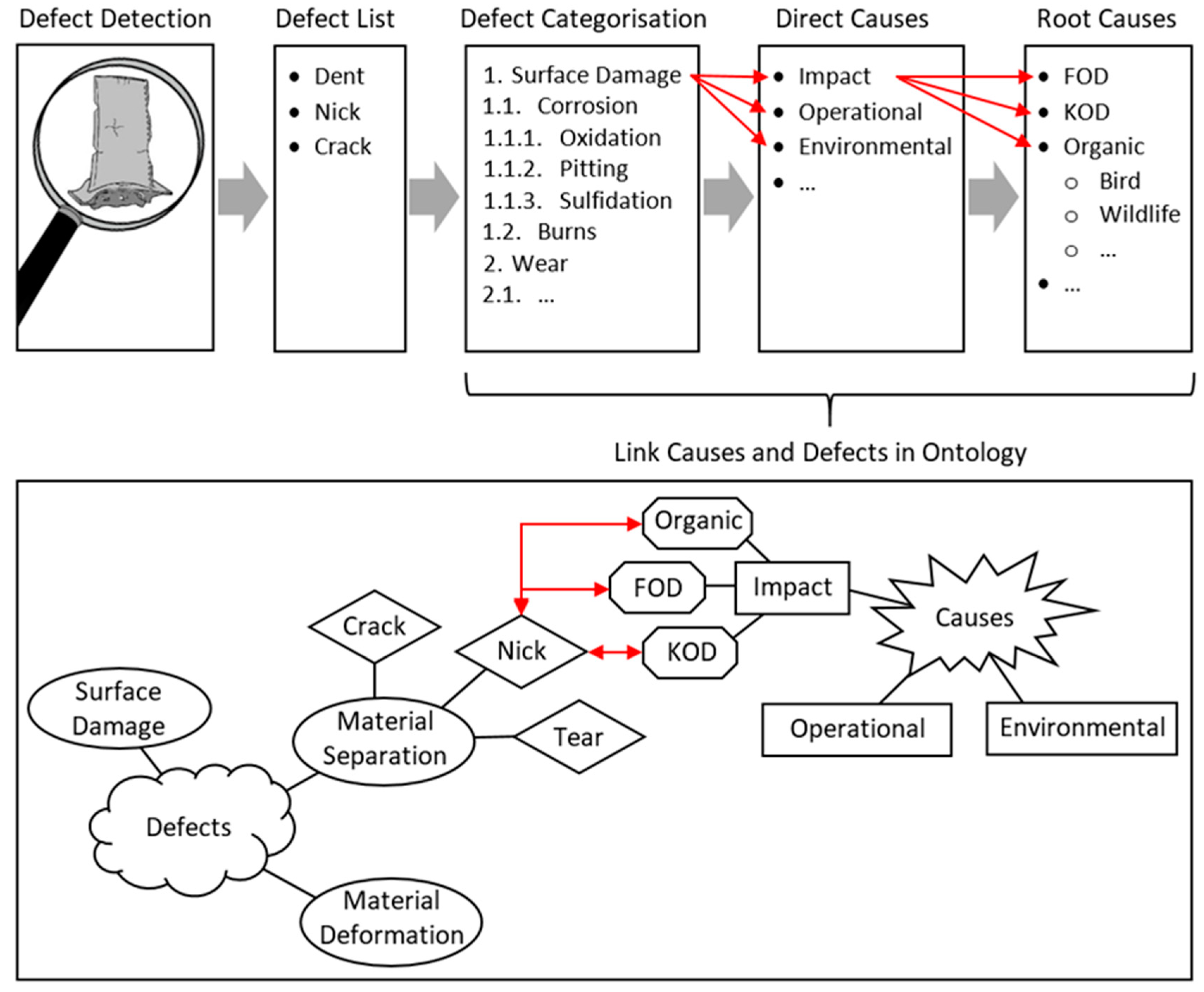
Our approach was to identify all defects on aero engine blades that can be found during visual inspection only. The procedure is shown in Figure 1. First, we examined the open literature on engine defects and failures, with a particular focus on engine blades. Additionally, we reviewed engine and maintenance manuals from engine manufacturers, such as Pratt and Whitney, Rolls Royce and International Aero Engine (a multinational joint venture engine consortium). Part of the literature review was also the examination of handbooks published by aviation authorities, such as the Federal Aviation Administration.
Then, we integrated our findings in an initial single comprehensive defect list. This list was further enhanced by our own insights gained from observation and personal communication with industry experts. For greater clarity and ease of understanding, we added our own defect images, taken during visual inspection of engine blades at an MRO facility.
Next, we evaluated different classification systems and categorised the defects based on the type of damage. The defect categories include ‘Surface Damage, Wear, Material Separation and Material Deformation’.
In parallel, we developed a second categorisation of potential causes grouped by the nature of the root cause from the operator perspective (e.g., hail, ice, rain, etc.), as well as by similar defect consequence for the blade (equi-finality). This list includes such items as ‘Environmental Impact, Operational Failure and Fatigue’.
Finally, we assigned the causes to the resulting defects. This was challenging as causes can lead to one or multiple defects, resulting in a complex intertwined network. The goal was to present it in an integrated and coherent manner. As there are multiple categorisations, we applied the ontology methodology to develop a logical representation structure. The benefit of an ontology is to visually present the relationships between different defects, causes and contributing factors in an appealing and easy-to-absorb way. In comparison to other causal mapping tools, such as cause–consequence diagrams, an ontology is able to show cross-links not only between cause and consequences, but also within the same class, that is, between a cause and another one, as well as between different types of defects [23,24]. Another benefit of the ontology is that it provides means of knowledge storage in a computer readable way [25]. No application of ontologies to blade defects is apparent in the literature. The specific ontology software used was ‘Protégé’ [26].
Ontologies have a wide range of applications and have been successfully applied to measure health and safety risks [27], engineer healthcare and workforce management systems [28], develop software server architectures [29] and emergency event models [30], as a database for gene clustering [31], and to represent multimedia data [32]. No application of blade defects is apparent in the literature.
4. Results
4.1. Blade Defect List and Taxonomy
Defects on engine blades were identified based on the existing literature and engine manuals. The initial result was an unstructured collection of defect terminologies with duplicated information, that is, different terms describing the same type of defect. These terminologies are labelled ‘equally used terms’ and can be used interchangeably.
To structure our defect collection, we looked into a possible classification system. There are several ways of categorising defects, corresponding to the lenses or perspectives of the audiences, as shown in Table 1. Each of them is valid and used for different purposes. For example, for investigators of an incident or accident, it is essential to know the root-cause and how such an event can be prevented in the future. In contrast, an MRO facility is interested in the location within the engine where the defect is most likely to occur, to identify parts needing to be replaced and therefore to be purchased.
Existing categorisations tend to focus on only one such perspective. We propose that a holistic categorisation may require the following attributes:
While the above may be ideal, for the purpose of this paper we only adopted the first attribute, that of damage type. The other attributes are left for potential future work. We then further refined that category. Four main damage categories were identified:
- Surface damage: Surface damages describes deviations from the nominal surface, such as roughness, waviness, lay and flaws [20]. This may include material separation and/or loss of base material or coating [19,21]. It is often aggravated by high air temperature, humidity, moisture and contaminated environments, such as salt from sea or de-icing treatments. [8]
- Material deformation: Material deformation is notable by significant change of the original contour of the part. The deformation can be caused by mechanical or thermal means [21].
We propose that potential causes vary for different types of defects. For example, we divided ‘Corrosion’ further into three subcategories, namely oxidation, pitting and sulfidation.
The resulting categorised defects are listed in Table 2. We informally validated this list by discussion with expert maintenance practitioners. This list is considered to be comprehensive for all engine blades, independent of the blade type, engine model and manufacturer. A detailed description of each defect is provided in Appendix Table A1.
4.2. Six Main Categories of Causes
Potential causes were collected based on literature, e.g., [8,39], aviation authority documents [19,38,40] and aircraft manufacturer [37]. There is a myriad of potential items that can cause a defect, and such lists, including our own, tend to lose coherence as more items are added. Single lists scale poorly as they grow. Therefore, a second classification system, orthogonal to the first, was introduced to represent the causes. This groups the items based on their nature and effect of the cause, i.e., similar items that lead to the same defect were grouped together.
We propose that six main cause categories are sufficient: Impact, Environmental causes, Operational causes, Poor maintenance, Poor manufacturing and Fatigue. The structured cause list is shown in Table 3.
The completeness of this list is limited to the second level as the number of items (causes) in lower levels would increase considerably and would go beyond what can be communicated in this paper. A few items were listed for the third level as representative of similar items. For example, ‘Left-behind Items’ represents everything in or close to the air-intake that can become FOD when inadvertently left behind. This includes but is not limited to such items as aircraft and engine fasteners, personal belongings, catering supplies, cabin cleaning, baggage, cargo, coins or operation vehicles, which are not listed individually [38,41]. The exceptions are maintenance tools and equipment [37] that are left behind during maintenance tasks, which are instead listed in the ‘Poor Maintenance’ section.
4.3. Integrated Cause–Defect Relationship
The inter-relations were then identified and the causes assigned to the defects. Identification of the cause–defect relationship was done by analysis of the research literature, discussion with expert maintenance practitioners, reference to the maintenance manuals [19,20,21] and general engineering principles. Hence, this set of relationships has a degree of validation, and provides a sufficient representation of the complexity of the real situation.
The links and inter-relations are complex. This is because a defect can result from multiple causes, and a cause can lead to multiple defects. Furthermore, a defect can cause another defect in combination with other factors that aggravate and accelerate the defect development. It is possible to show cascade failures using this tabular data, as shown in the next section.
However, we do not claim that the list is perfectly comprehensive, nor entirely validated. It merely represents what is commonly known about the cause–defect relationship. While it may be ideal that each of these relationships be verified, that would require new research and a changed level of record-keeping in the industry (see Discussion). Nor have we addressed the other ‘Damage Attributes’ identified above. Nonetheless, in principle, such additional data could be added to the table as additional fields.
The cause–defect list is believed to be adequate for the maintenance audience since it was validated in that field, but we caution that it may not be sufficiently exhaustive for the accident investigation audience.
4.4. Representing Defect Development with an Ontology
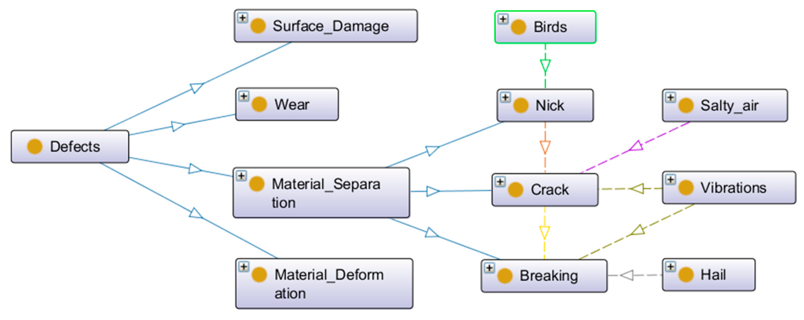
Blade defects are often caused by occurrence and a combination of different damage mechanisms, such as fatigue, creep, corrosion, erosion, sulfidation, foreign object damage and vibration [2]. For example, a foreign object impact, such as a bird, can cause a nick that breaks the material flow and concentrates stresses, which initiates the development of a crack. The crack in turn can result in material lift-up or breaking away of a significant piece of the blade.
This chain of defect development can be further accelerated and aggravated by several factors, such as environmental conditions, fuel quality, operating settings, cyclic loads and engine and maintenance history. In the case of crack development, contributing factors include salty air and vibrations, whereby hail could be the initiator for the breaking of blade material. This type of defect development is unable to be represented by simple lists.
The inter-relations, causal links and cascade effects lead to a complex network of defects and causes. This is difficult to visualise. We applied an ontological method to express this complex network of information. The ontology provides a rich conceptual framework that allows causes to be assigned to defects in a systematic and coherent process.
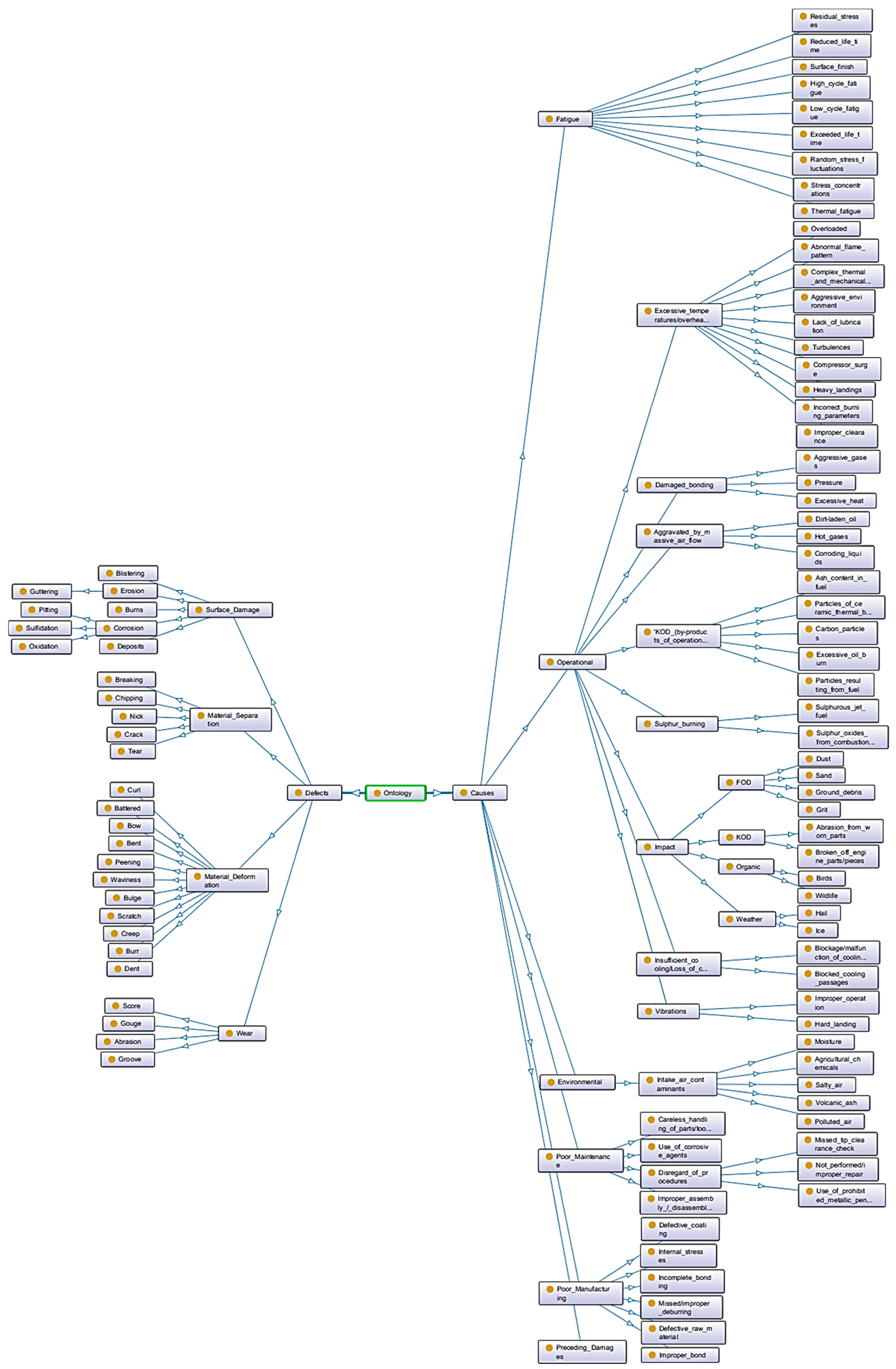
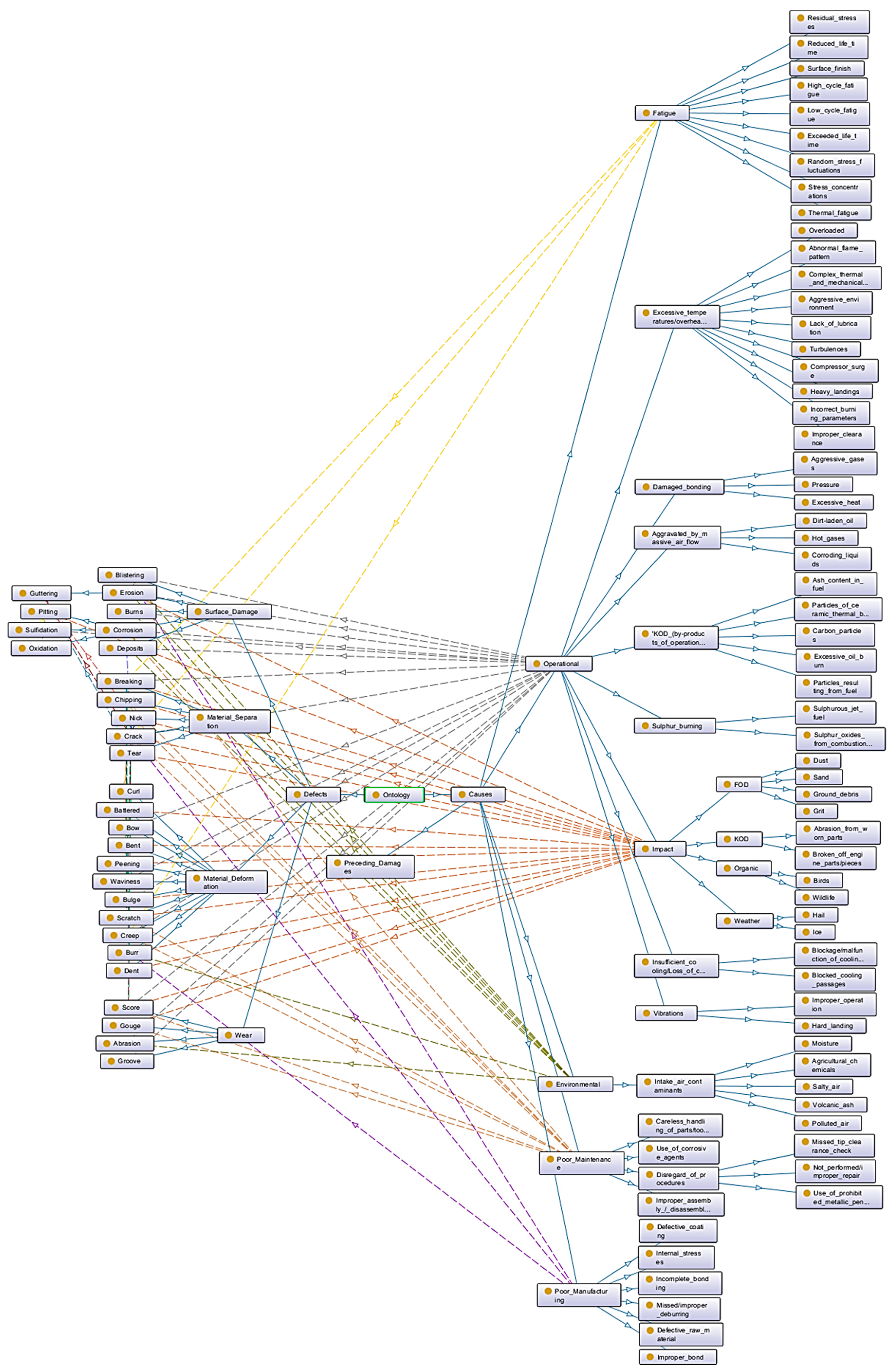
We used Web Ontology Language (OWL) and Protégé software to build a knowledge base and express relationships, hierarchies and object properties, and applied mapping analysis to visualise the network. The ontology was developed based on the cause–defect table as shown in Table A1. For the purpose of this paper, and to avoid an overloaded ontology, we only mapped causes up to the second level. However, in the software, the ontology can be fully expanded to show all details and inter-relations.
A simplified extraction of the ontology explaining the above case scenario is shown in Figure 2.
In rare, but possible cases the effects can even flow upstream and damage upstream engine sections. This can be seen in burned-out engines, whereby a broken-off compressor blade gets shredded and the small titanium pieces catch fire, which ignites an upstream blade fire.
5. Discussion
5.1. Summary of Outcomes
This work makes several novel contributions. First, it provides a single comprehensive collection of engine blade defects. This may support standardisation and enable ease of communication by providing a defect definition and description. This list summarises different terminologies for the same defect and provides a German translation. This may be helpful for the avoidance of confusion as many engine manufacturers and MRO service providers are based in Germany.
Second, we proposed a new classification system for both engine blade defects and root-causes. The defects were categorised based on the type of damage, and the causes based on their nature and resulting damage. These two categorisations were combined into a blade defect–cause taxonomy. This appears to be the first systematic taxonomy for blade defects based on the type of damage. In contrast, existing literature [18], engine manuals [20,21] and aviation handbooks [19] list the defects alphabetically, which of course is language-specific.
Third, the defects are described in more detail than previous publications. This has the potential to enable a better understanding, and distinguish different defects from another. Furthermore, in addition to the defect description, a representative image was taken for each defect and added to the list. This helps to better retrieve visually the differences between the defects, and may be useful for MRO quality systems.
Fourth, we applied an ontology to link the potential causes to the defects and show the inter-relations, causal links and cascade effects. This represented the complex relations and interactions between defects, causes and temporal progression of events. This has potential to support aircraft engine inspectors to guide their maintenance tasks, as well as investigators to identify the root-causes after a defect leads to severe damage.
5.2. Implications for Practitioners
The defect list offers a precise definition and description of visually detectable damages. The taxonomy of blade defect-causes may be practically useful because it offers a standardised defect terminology, which currently does not exist in the industry. This has the potential to support MRO quality systems, reduce confusion between different defects, avoid confounding defects with causes and provide a common technical communication language between different departments, suppliers, manufacturers, maintenance providers and customers. An example of a possible practical use of the taxonomy by the MRO industry could be to provide the basis for training maintenance staff to understand the differences between various defects. This is a key factor in quality systems, minimisation of non-value-added time and responsiveness to clients.
The taxonomy could be applied in other ways too. It may be of relevance when investigations are performed to find the root-cause after an aircraft incident or accident. If the defect is known, then the ontology could reveal all potential causes and cascading effects that may have led to the defect.
Another potential application is for the ontology to be used as an inspection support tool to analyse engine and maintenance history for unexpected events. For example, if it were known that an engine had suffered a bird ingestion, then the ontology could be interrogated to identify the possible defects. This may support the inspection task by guiding the worker during the inspection process, and help prioritise such inspections as may be necessary to determine the health of the engine.
5.3. Limitations of the Work
This work has several limitations. First, the depth of causation is limited to the second level as shown in Figure 3. This is also the reason why the links in the ontology between causes and defects were only displayed to the second level of causation (Figure 4). The third level is only representative as there are, for example, hundreds of objects that may cause a dent. We felt it was not useful to list all those items, which only results in a massive ontology. Likewise, we did not further split up root-causes in subcategories. For example, for bird ingestion, we did not differentiate between say a sparrow and an albatross as the expected type of defect remains the same; only the extent of damage increases with increasing size of the ingested item.
The second limitation is that the defect list has been created for visual inspection only. It does not include any defects or damages that can be detected by applying other NDT methods commonly used in aviation maintenance, such as ultrasonic, radiography, eddy current, three-dimensional (3D) laser or infrared thermography [42].
The third limitation is that even though the ontology can show all potential causes and loops of causalities, it cannot describe to what extent each factor contributes towards the defect. Likewise, the likelihood is not shown. This is due to the lack of data and limitations of the ontology itself.
5.4. Limitations of the Ontological Approach
It was interesting to apply the ontological approach to the problem of turbine blades. The ontology was successful in representing the convolution of the two categories, defect versus cause. This is a difficult situation to represent due to the many-to-many causalities, and the temporal and cascade effects. However, ultimately, we were dissatisfied with the ontology, because of the intrinsic limitations of the method, or perhaps of the software. There are multiple limitations. The first is that the ontology cannot handle mathematic calculations or probability representation. This is because the OWL is based on first-order logic and does not have any inherent mechanisms for logic [43]. Moreover, the ontology cannot express logical gates, which is relevant to define whether one or multiple causes or conditions must be present before a damage may occur. It is therefore not possible to differentiate between a cause that lead to a defect on its own, and contribution factors that only accelerate the defect development but cannot cause the defect independently.
Second, the ontology does not provide an easy mechanism for forward or backward chaining, which is needed for the prediction and diagnosis activities. A related limitation of the ontology is its limited export options. We could not find software, such as an expert system, that was able to further process the data without additional extensive code writing.
Third, the ontology provides a limited user interface for inserting and extracting data. In the present work, the ontology is not fully automated; instead, it requires manual input via a spreadsheet and manual knowledge extraction via the ontology graph. The manual nature of the interaction creates the risk that the ontology sets the focus on the most likely defect. In some cases, this might not be the present or only defect that occurred. It is important to understand the ontology as a support tool and not as a means to skip the inspection for any other defect type. Consequently, the ontology approach is not yet robust enough that it could be given to maintenance technicians to use.
5.5. Implications for Further Research
A number of possible lines of further research are suggested.
In principle, this work is expandable to other parts of gas turbine engines, such as annulus fillers, cases, discs, rotors, air seals, bearings, shafts, drums, liners, fuel nozzles and ducts. It is conceivable that the introduced defect list and ontology is further applicable to other industries where turbines with blades are deployed, such as marine craft propulsion [4], steam or hydropower generation [44,45] and even wind power systems [46,47]. The work was developed for the aviation maintenance industry, in particular for the visual inspection of gas turbine engine blades, but it may be possible to apply more widely.
Another potential research question would be to extend the taxonomy to include likelihoods of causes and defects. Engine data of unexpected events are available, but there are several limitations with assigning frequencies to different defects. One of the challenges with this is the need to collect more precise data. At present, MRO shops do collect information, such as how many engines had an engine visit due to FOD. However, current industry practices tend not to differentiate the subcategories of defect, e.g., between a nick, dent, breaking, etc. Similarly, the data on where the defect occurred are not commonly recorded, e.g., where on the blade edge or zone on the airfoil. Another limitation is that only direct causes, if any, are reported unless the blade defect caused an incident or accident and a root-cause investigation is performed. However, as those events are relatively rare, there is not much data available and this makes it difficult to assign probabilities to root-causes and contribution factors. The data gathering is further complicated by a manual data extracting process from several databases, making it a search-intensive and time-consuming task. Consequently, the quantification of likelihoods would require (a) adoption of a common taxonomy of defects, and (b) changes in MRO practices to defect recording. The current work offers a solution to the first part, and hence it is not impossible that progress may be made on the quantification issue. For the practical applicability and further enhancement of the system, we recommend the collection of sufficient defect data in collaboration with industry experts. Frequencies would need to be assigned to each cause and defect, as well as the associated defect location on the airfoil.
There is also potentially a computer science research strand. We have shown that ontologies provide an option for storing a knowledge base. However, the ontology prototype revealed that there are many limitations. The pressing need is for inclusion of an expert system. Several researchers have explored the feasibility of an ontology-based expert system for ‘pest and disease management’ [48,49], ‘analysis of coffee beans’ [50], ‘suspicious transactions detection’ [51], ‘process planning’ [52], ‘product consultation’ [53], ‘financial rating’ [54] and ‘medical diagnosis’ [55,56,57]. For the development of an expert system, we recommend to first determine the data properties and restrictions and create rules using Semantic Web Rule Language (SWRL). The rules need to be added to the ontology and support complex mathematical expressions. Next, a semantic reasoner, that is Hermit, Pellet, Racer, Jess, etc. [51] might be used to evaluate the rules for consistency and derive new, non-explicitly expressed knowledge [51,58]. Last, an easily accessible user interface needs to be developed to query information from the ontology. The user interface could be in form of a web-based homepage or offline application programmed in C++, Java, HTML, Visual Basic, etc. [49,58,59].
A final research suggestion is the development of an automated inspection support tool. Research could explore the potential of a smart inspection system, whereby the defects are automatically detected, evaluated, and appropriate maintenance actions proposed based on the inspection findings and historical data of the engine. It may be possible to use artificial intelligence (AI) for the image processing, and then an expert-system ontology for the logical processing. Ideally, this would also have access to quantitative data on defect likelihood. This could potentially improve the inspection and parts procurement process, enable early determination of the level of disassembly and required repair actions, reduce engine downtime and ultimately reduce costs for both the MRO provider and airline.
6. Conclusions
This paper defines engine blade defects, assigns root-causes, shows causal links and cascade effects and provides a taxonomy system. Defect types were identified from the literature and maintenance manuals, and categorised into Surface Damage, Wear, Material Separation and Material Deformation. A second categorisation identified potential causes of Impact, Environmental causes, Operational causes, Poor maintenance, Poor manufacturing and Fatigue. These two categorisations were integrated with an ontology.
The work provides a single comprehensive illustrated list of engine blade defects, and a standardised defect terminology, which currently does not exist in the industry. It proposes a taxonomy for both engine blade defects and root-causes, and shows that these may be related using an ontology.
This has potential to support aircraft engine inspectors to guide their maintenance tasks, as well as investigators to identify the root-causes after a defect may lead to severe damage.
Several potential research directions are suggested whereby the principles established here might be enhanced and developed into a smart inspection support tool with the potential to optimise visual inspection processes, thereby contributing positively to maintenance planning and procurement and quality.
Supplementary Materials
The following are available online at https://www.mdpi.com/2226-4310/6/5/58/s1, Figure S1: Ontology without causation links, Figure S2: Ontology with second-level causation links, File S3: Ontology OWL file.
Author Contributions
J.A. and D.P. conceptualised the overall framework. The data collection, categorization and visualisation was undertaken by J.A. Supervision and project direction was provided by D.P. The original draft was written by J.A. and all authors contributed to the subsequent editing and review.
Funding
This research project was funded by the Christchurch Engine Centre (CHCEC), a maintenance, repair and overhaul (MRO) facility based in Christchurch and a joint venture between the Pratt and Whitney (PW) division of United Technologies Corporation (UTC) and Air New Zealand (ANZ).
Acknowledgments
We sincerely thank staff at the Christchurch Engine Centre for their support and providing insights into visual inspection and blade defects. In particular, we want to thank Tim Coslett, Marcus Wade, Jamie Murray, Matthew Austin, and Blair Robertson.
Conflicts of Interest
J.A. was funded by a PhD scholarship through this research project. The authors declare no other conflict of interest.
Appendix A. Root-Cause and Defect List
The defect definitions originate from different engine and maintenance manuals [20,21] and aviation authority documents [19,36,38].

Table A1.
Full root-cause and defect list.
| Defect | Equally Used Terms | German Translation | Description | Potential Causes | Sources of Cause | Image |
|---|---|---|---|---|---|---|
| 1. Surface Damage | Surface texture | • Oberflächen-beschädigung | Deviations from the nominal surface, such as waviness, roughness, lay and flaws [60]. May include material separation and/or loss of material or coating. | |||
| 1.1. Corrosion | - | • Korrosion | Definition: Slow deterioration of part surface or its coating by a chemical or electrochemical reaction with atmospheric or hot gas contaminants in the working environment. Parts made of aluminium and high strength alloys, as well as some stainless steels can corrode when exposed to tensile stresses [18]. | 1. Environmental | 1.1. Intake air contaminants 1.1.1. Pollution and soot from industry or forest fires 1.1.2. Volcanic ash 1.1.3. Salt deposits from sea air or de-icing treatments [17] 1.1.4. Agricultural chemicals 1.2. Accelerated by: 1.2.1. Warm temperatures 1.2.2. Salts 1.2.3. Acids |  Corrosion pitting and decolourisation of LPT stage 4 vane |
| 2. Poor Maintenance | 2.1. Carbon alloy or metallic pencils (used for markings) 2.2. Corrosive agent 2.2.1. Fire extinguisher agents | |||||
| 3. Operational | 3.1. Higher burning temperatures 3.1.1. Complex thermal and mechanical loads 3.1.2. Overload 3.1.3. Aggressive environment | |||||
| 1.1.1. Oxidation | • Rusted | • Oxidierung | Definition: Chemical reaction between oxidants or other corrosive contaminants in the hot gases and the blade surface (coating), or in its absences, with the base alloy. | 1. Pre-existing damages | 1.1. Missing coating 1.1.1. Impact→See ‘Impact’ |  Oxidised deposits on HPC blades |
| 2. Environmental | 2.1. Salt deposited on the surface reacts with ferrous-based metals or deposits when getting into contact with moisture-laden air 2.2. Chemical reactions of the part with intake are contaminants | |||||
| 1.1.2. Pitting | • Pustules |
| Definition: Small, irregularly shaped cavities or hollows, usually dark bottomed, in the blade surface, herby material has been removed by corrosion or chipping. Sulphidation of pitting holes is called sulphidation pits or pustules. | 1. Pre-existing damages | 1.1. Corrosion 1.1.1. Breakdown of surface by oxidation 1.1.2. Chemical reaction due to corrosive contaminants |  Pitting on stage 2.5 stator vane airfoil |
| 2. Operational | 2.1. Overloading 2.2. Inclusion removal in operation mode 2.3. Presence of unwanted particles | |||||
| 3. Impact | 3.1. FOD 3.2. KOD 3.3. Organic damage | |||||
| 1.1.3. Sulfidation | • Sulphidation | • Sulfidierung | Definition: Sulfidation, or sulphur corrosion describes a chemical process whereby sulphur containments in the ingested air reacts with the coating and/or base material of engine blades under heat influence. This defect can be found in the engine’s turbine hot section where temperatures are high. It appears as a greenish to pale blue discolouration and as raised, blistered surface similar to corrosion pits. | 1. Environmental | 1.1. Sulphur containments in intake air in form of: 1.1.1. Deposited salts 1.1.2. Agricultural chemicals 1.1.3. Airborne particles from forest fires 1.1.4. Polluted air |  Sulfidation on LPT stage 4 blade root |
| 2. Operational | 2.1. Sulphurous jet fuel 2.2. Sulphur oxides from combustion and airborne salts, such as sodium, react with water (by-product of fuel combustion) and creates a sulfric acid. | |||||
| 1.2. Burns |
| • Verbren-nungen | Definition: Surface and/or structural damage due to excessive heat, visible as stain or discolouration and, in severe cases, by loss or flow of material. Often the term ‘overheated’ is misleadingly used as a defect. In fact, ‘overheated’ is the cause and ‘burns’ are one possible consequence of it. The V2500 Engine Manual further distinguishes between:
| 1. Operational | 1.1. Excessive heat 1.1.1. Abnormal flame pattern 1.1.2. Incorrect burning process or parameters 1.1.3. Lack of lubrication 1.1.4. Improper clearance 1.1.5. Overloaded 1.1.6. Hard landing 1.2. Insufficient cooling 1.2.1. Blocked cooling passages 1.2.2. Blockage or malfunction of the cooling airflow |  Burned HPT T1 blade with burn through |
| 2. Environmental | 2.1. Aggravated by high air temperature 2.2. Aggravated by heat, moisture, and contaminated environment | |||||
| 1.3. Blistering |
|
| Definition: Raised areas that indicate a separation of pieces of a coated surface from a base metal, often evident as peeling and/or flaking. | 1. Operational | 1.1. Damaged bonding by: 1.1.1. Aggressive gases 1.1.2. Pressure 1.1.3. Excessive heat→see ‘Burns’ |  Blistering and loss of coating of LPT blade |
| 2. Environmental | 2.1. Contaminants in airborne | |||||
| 3. Poor manufacturing | 3.1. Improper bond 3.2. Incomplete bonding 3.3. Defective coating | |||||
| 1.4. Erosion | - |
| Definition: Erosion describes the surficial abrasion of material by the flow of fluids or gases and thus leads to wear and destruction of engine parts. Heat or particles in the hot gases accelerates this process. The impact of particles typically larger than 20 µm is especially apparent on the leading edge of the blade. It is visually recognisable by a rough surface with stripes or marks in the direction of the particle; often in the air flow direction. The amount of particles entering the engine and leading to erosion is significantly higher during landing and take-off. | 1. Impact | 1.1. FOD: Solid particle impacts 1.1.1. Grit 1.1.2. Fine sand 1.1.3. Dust 1.1.4. Ground debris 1.2. KOD: Broken-off pieces from upstream engine parts |  Erosion on leading edge of fan blades |
| 2. Environment | 2.1. Moisture 2.1.1. Water droplets on inlet edge of a rotating blade 2.2. Salty air 2.3. Polluted air | |||||
| 3. Operational | 3.1. KOD: By-products of operation 3.1.1. Excessive oil burn 3.1.2. Carbon particles (from fuel injection) 3.1.3. Particles of ceramic thermal barrier coatings (detaching due to thermal shock) 3.2. Aggravated by massive air flow 3.2.1. Hot gases 3.2.2. Corroding liquids 3.2.3. Dirt-laden oil 3.2.4. Turbulences | |||||
| 1.4.1. Guttering | - | • Furchen | Definition: A deep, concentrated erosion that results from enlargement of a crack, tear, or nick exposed to hot gases and/or concentrated combustion chamber flames. | 1. Enlargement of pre existing defects by burning | 1.1. Cracks 1.2. Nicks 1.3. Tears |  Erosion of a preceding crack at nozzle guide vane |
| 1.5. Deposits (No material separation or loss, but additional particles on surface) |
| • Ablagerungen | Definition: Particles from foreign material, by-products during operation, or material from upstream part separation that are collected by centrifugal force and built up an extra layer on the casing, vanes and compressor blades. Foreign material can be apparent in solid or liquid state and may or may not be adherent to the surface of an engine part. Non-adherent particles are normally carted off by the air flow and may cause no further damage to the engine. | 1. Environmental | 1.1. Intake air contaminants 1.1.1. Polluted air 1.1.2. Volcano ash 1.1.3. Salty air 1.1.4. Particles in air near ground (dirt, oil, soot) 1.2. KOD 1.3. Organic 1.3.1. Birds 1.3.2. Wildlife |  Deposits on LPC stage 2.5 blades  Deposits on LPT vane  Deposits on HPC stage 3 blade |
| 2. Operational | 2.1. KOD: By-products of operation 2.1.1. Excessive oil burn 2.1.2. Fuel (ash content) | |||||
| 2. Wear |
| Material removal from the part by mechanical means. | ||||
| 2.1. Abrasion |
|
| Definition: Abrasion or galling describes a roughened area usually caused by severe chafing or fretting action resulting from slight relative movement of two surfaces under high contact pressure during engine operation. The damage characteristics include microstructure changes of the part surface material or coating, surfaces debris, wear or material removal and reduced fatigue capability [35]. The degree of abrasion varies from ‘light’ to ‘heavy’ depending upon the extent of reconditioning required to restore the worn surface. The abrasion effect is accelerated by the presence of foreign material in addition to the detached abrasion material. Chafing is often used as synonym for the same defect description. However, chafing shall be understood as action resulting in deterioration of the surface condition rather than as the description of the damage itself. Note: Not to be confused with scores, scratches or gouges. Example:
| 1. Operational | 1.1. Wear 1.1.1. Particles from abrasion are self-accelerating 1.2. Abnormal relative movement of parts 1.3. Parts out of alignment |  Abrasion of HPC stage 6 blade cheeks |
| 2. Environmental | 2.1. FOD 2.1.1. Unwanted material between parts | |||||
| 2.2. Gouge | • Gouging |
| Definition: A furrowing condition where material from the surface has been displaced and removed by cutting or tearing action. | 1. Impact | 1.1. FOD 1.1.1. Large, sharp unwanted foreign object 1.2. KOD |  Gouge on retaining slot of a HPC stage 5 blade |
| 2. Poor Maintenance | 2.1. Improper (dis-) assembly 2.2. Careless handling | |||||
| 2.3. Groove |
|
| Definition: A smooth, rounded furrows, such as tear marks, whose edges have been polished due to concentrated wear. | 1. Operational | 1.1. Concentrated wear 1.2. Abnormal relative motion of parts 1.3. Parts out of alignment |  Groove in retaining slot of a HPC stage 4 blade |
| 2.4. Score | - |
| Definition: Multiple scratches of significant depth are called a score, which is often caused by sharp objects during engine operation. Contrary to scratches, scores show some removal of material. | 1. Operational | 1.1. KOD 1.1.1. Presence of chips between parts |  Fan blade scoring |
| 2. Poor maintenance | 2.1. Careless assembly or disassembly techniques | |||||
| 3. Impact | 3.1. FOD 3.2. KOD 3.3. Organic damage | |||||
| 3. Material Separation | • Material-trennung | Material is split but not removed. | ||||
| 3.1. Chipping | • Spalling |
| Definition: Chipping describes mechanical separation of small pieces of blade material or coating often apparent on edges, corners or surfaces leaving a sharply roughened area of irregular shape. Often apparent on clappers. Note: Not to be confused with flaking. | 1. Pre-existing defects | 1.1. Excessive stress concentration 1.1.1. Nicks 1.1.2. Surface cracks 1.1.3. Scratches 1.1.4. Peening 1.2. Fatigue 1.3. Subsurface inclusions |  Clapper wear on HPC stage 3 rotor blade |
| 2. Poor maintenance | 2.1. Careless handling 2.2. Improper (dis-)assembly | |||||
| 3. Impact | 3.1. FOD 3.2. KOD | |||||
| 3.2. Crack | • Fissure |
| Definition: A material separation or partial fracture of material evidenced as a linear opening that can easily be seen and which can cause the material to break. The depth can vary from a few thousandths of the full part’s thickness to its full thickness. The latter usually leads to full breakage of the part into one or more pieces. A crack is often an expansion of a pre-existing defect such as a nick, scratch or gouge. Note: Not to be confused with a hairline crack, which cannot be detected by the naked eye and where special fluorescent or magnetic penetrants are required to detect the defect. | 1. Impact | 1.1. FOD 1.2. KOD 1.3. Organic damage |  HPT T2 blade cracked airfoil  Crack in HPT T1 blade tip |
| 2. Operational | 2.1. Overheating 2.1.1. Localised hot spots 2.1.2. Overload 2.1.3. Hard landing 2.2. Vibrations | |||||
| 3. Pre-existing defects | 3.1. Corrosion 3.2. Nicks 3.3. Scratches 3.4. Scores 3.5. Gouges | |||||
| 4. Fatigue | 4.1. Random stress fluctuations 4.2. Stress concentrations 4.3. Surface finish 4.4. Residual stresses 4.5. High cycle fatigue 4.6. Thermal fatigue | |||||
| 5. Poor maintenance | 5.1. Careless handling of parts or tools 5.2. Improper (dis-) assembly 5.3. Left behind hand tools | |||||
| 6. Poor manufacturing | 6.1. Internal stresses (from machining) 6.2. Defective (raw) material | |||||
| 3.3. Breaking |
|
| Definition: Complete separation of a blade into two or more large-sized pieces by an external force or internal stresses. Different defects, such as cracks, nicks, dents and notches, often precede and lead in combination with one of the causes to material separation and a broken engine blade. | Resulting from pre-existing defects in combination with: | Cracks, nicks, dents, notches → See individual defect section for possible causes |  Broken off HPC blade |
| 1. Impact | 1.1. FOD 1.1.1. Left behind items 1.2. KOD 1.3. Organic impact | |||||
| 2. Fatigue | 2.1. Thermo-mechanical creep | |||||
| 3. Operational | 3.1. Stresses caused by heat 3.2. Sudden overload | |||||
| 3.4. Nick | • Notch |
| Definition: A small, sharp cut on the surface or edge of a part caused by a striking object. A nick has a characteristic V-shaped bottom, breaks the material flow and concentrates stresses. This weak point may initiate the development of cracks, leading to a decreased lifetime of the blade. The damage occurs often at or close to the leading edge of a blade [61]. | 1. Impact | 1.1. FOD 1.1.1. Sand 1.1.2. Fine unwanted particles 1.2. KOD 1.3. Organic damage 1.3.1. Birds 1.3.2. Wildlife |  Fan blade trailing edge nick  HPC stage 8 blade |
| 2. Poor maintenance | 2.1. Careless handling of parts or tools 2.2. Improper (dis-)assembly | |||||
| 3.5. Tear | - |
| Definition: Separation of material by tensile stresses imposed by a sharp object. A nick may have been pre-existent and was enlarged by a heavy impact. It is apparent by ragged or irregular edges. | May result from pre-existing defects in combination with or by: | Nicks |  HPC stage 5 blade tear after organic impact |
| 1. Impact | 1.1. FOD 1.1.1. Significant tough and sharp foreign object 1.1.2. Left-behind items 1.2. KOD | |||||
| 4. Material Deformation | • Material-verformung | Extensive change of the original contour of a part. | ||||
| 4.1. Bent |
|
| Definition: Angular change from the original shape or contour usually the cause is a lateral force. | 1. Impact (lateral) | 1.1. FOD 1.2. Organic impact 1.2.1. Bird ingestion |  HPC blade bent  HPC stage 8 blade bent |
| 4.2. Bow | • Bowed |
| Definition: A bow is a stress-included bent or curve in the blade or vane contour. In comparison to bent damage, bows are indicated by larger curve radii. Additionally, the damage is caused by internal stresses arising from excessive heat, pressure, or forming, rather than by lateral impact resulting from foreign object hits. | 1. Operational | 1.1. Excessive heat 1.2. Uneven application of heat 1.3. Structural stresses 1.4. Thermal overload | |
| 4.3. Bulge |
|
| Definition: An outward bending or swelling of displaced material without separation resulting from excessive heat. This defect often occurs on the leading edge. | 1. Impact | 1.1. FOD (dull objects) 1.2. Organic impact | |
| 2. Operational | 2.1. Excessive heat | |||||
| 4.4. Burr |
|
| Definition: A narrow ridge of material, roughed edge or imperfection on the surface of a material raised above the general contour of the part. It is most likely appears along an edge. | 1. Poor manufacturing | 1.1. Missed or improper deburring after machining |  Burr on blade tip resulting from tip rub |
| 2. Environmental | 2.1. Excessive wear 2.2. Deposits | |||||
| 3. Impact (sharp hitting object during operation) | 3.1. FOD 3.1.1. Ice or hail 3.1.2. Sharp objects 3.1.3. Left-behind items 3.2. KOD | |||||
| 4.5. Battered | - |
| Definition: Damage on a part that is repeatedly hit and as a consequence severely deformed. | 1. Impact | 1.1. FOD 1.1.1. Hail 1.1.2. Ice 1.1.3. Ground debris |  Heavy battered fan blade |
| 4.6. Creep |
|
| Definition: Continuous stretch or deformation of a part in operation under high temperatures, and/or centrifugal loads and high rotational speeds (latter impacts rotating parts only). Creep is predominant in the engine’s hot section (turbine) and in the last blade stages of high-pressure compressors (HPC), whereby the blades elongate towards the surrounding shroud case, and the shrouds expand under thermal influence. In order to improve the engine efficiency, the clearance between blades and casing shall be kept as minimal as possible. When heavy operations cause severe blade elongation, the blade tips rub against the non-moving shrouds. The resulting damage is known as tip rub. The V2500 engine manual further distinguished between:
| 1. Operational | 1.1. Loss of cooling 1.1.1. Blocked cooling passages 1.1.2. Blockage or malfunction of the cooling airflow 1.2. Continued and/or extensive heat accelerated by high rotating speeds and centrifugal forces 1.2.1. Turbulences 1.2.2. Heavy landings 1.2.3. Overloaded 1.3. Deposits on casing 1.4. Compressor surge |  HPC stage 11 tip rub  Fan blade tip rub against fan case |
| 2. Fatigue | 2.1. Creep cracking 2.1.1. Random stress fluctuations 2.1.2. Stress concentrations 2.2. Life time of part exceeded 2.3. Shortened lifecycle caused by operational means | |||||
| 3. Poor maintenance | 3.1. Inspection procedures not correctly followed 3.1.1. Missed tip clearance check 3.1.2. Not performed or improper repair, e.g., blades not trimmed to restore minimum tip clearance | |||||
| 4.7. Curl |
|
| Definition: A rounded fold in a rotating part after contact with a fixed, non-moving part. This defect can be observed after a blade tip rubbed against the engine case (see ‘tip rub’). | 1. Tip-rub | 1.1. Elongation/creep of blade (see ‘3.9 Creep’) 1.1.1. Heavy landings 1.1.2. Overloaded 1.2. Deposits on casing 1.3. Compressor surge 1.4. Missed maintenance inspection or incorrect procedures during maintenance inspection of tip clearance |  HPC stage 1.5 blade tip curl |
| 4.8. Dent | - |
| Definition: Damage to the surface of a part caused by mechanical impact of a dull object. A dent is visible as small, smooth indention with rounded edges, corners and bottom. Material is displaced but not removed. Often, dents can be found at or close to the leading edge of a blade [61]. A cluster of multiple dents on the leading edge can result in waviness of the blade. | 1. Impact | 1.1. FOD 1.1.1. Hail 1.1.2. Ice 1.1.3. Left-behind items 1.2. KOD 1.3. Organic damage 1.3.1. Birds 1.3.2. Wildlife |  Dent on leading edge of LPT stage 5 vane |
| 4.9. Peening | - |
| A group of very small dents caused when a part is repeatedly hit is called peening. | 1. Impact | 1.1. FOD 1.1.1. Hail 1.1.2. Ice |  HPC stage 4 blade root  LPC stage 2.5 blade |
| 4.10. Scratch | - | • Kratzer | Definition: Shallow, thin lines, marks or dragged indentations on either the coating (if present) or the material surface caused by movement of sharp foreign objects, careless handling or improper assembly. Scratches have a sharp bottom and material is usually not removed. | 1. Impact | 1.1. FOD (fine foreign particles) 1.1.1. Airborne particles 1.1.2. Fine sand and dust 1.1.3. Polluted air 1.1.4. Volcano ash |  LPT stage 7 blade scratched on airfoil surface |
| 2. Poor maintenance | 2.1. Careless handling of parts or tools 2.2. Improper (dis-) assembly | |||||
| 4.11. Waviness | - |
| An engine blade that has been deformed under influence of high temperatures is called waviness (The term ‘waviness’ originates from the FAA Aviation Maintenance Handbook). | 1. Operational | 1.1. Loss of cooling 1.2. Continued and/or extensive heat accelerated by high rotating speeds and centrifugal forces 1.2.1. Turbulences 1.2.2. Heavy landings 1.2.3. Overloaded |
References
- National Academies of Sciences Engineering and Medicine. Commercial Aircraft Propulsion and Energy Systems Research: Reducing Global Carbon Emissions; The National Academies Press: Washington, DC, USA, 2016; p. 122. [Google Scholar]
- Kumari, S.; Satyanarayana, D.; Srinivas, M. Failure analysis of gas turbine rotor blades. Eng. Fail. Anal. 2014, 45, 234–244. [Google Scholar] [CrossRef]
- Dewangan, R.; Patel, J.; Dubey, J.; Prakash, K.; Bohidar, S. Gas turbine blades—A critical review of failure at first and second stages. Int. J. Mech. Eng. Robot. Res. 2015, 4, 216–223. [Google Scholar]
- Rao, N.; Kumar, N.; Prasad, B.; Madhulata, N.; Gurajarapu, N. Failure mechanisms in turbine blades of a gas turbine Engine—An overview. Int. J. Eng. Res. Dev. 2014, 10, 48–57. [Google Scholar]
- Rani, S. Common Failures in Gas Turbine Blade: A critical Review. Int. J. Eng. Sci. Res. Technol. 2018. [Google Scholar] [CrossRef]
- Mishra, R.; Thomas, J.; Srinivasan, K.; Nandi, V.; Raghavendra Bhatt, R. Failure analysis of an un-cooled turbine blade in an aero gas turbine engine. Eng. Fail. Anal. 2017, 79, 836–844. [Google Scholar] [CrossRef]
- National Transportation Safety Board (NTSB). Southwest Airlines Flight 1380 Engine Accident. Available online: https://www.ntsb.gov/investigations/Pages/DCA18MA142.aspx (accessed on 3 November 2018).
- Carter, T.J. Common failures in gas turbine blades. Eng. Fail. Anal. 2005, 12, 237–247. [Google Scholar] [CrossRef]
- Yuan, Z. Borescope Inspection Management for Engine. IOP Conf. Ser.: Earth Environ. Eng. 2018, 182, 012013. [Google Scholar]
- Nickles, G.; Him, H.; Koenig, S.; Gramopadhye, A.; Melloy, B. A Descriptive Model of Aircraft Inspection Activities. Federal Aviation Administration. Available online: https://www.faa.gov/about/initiatives/maintenance_hf/library/documents/media/human_factors_maintenance/a_descriptive_model_of_aircraft_inspection_activities.pdf (accessed on 27 October 2018).
- Yuan, Z. Borescope inspection for HPT blade of CFM56-7B engine. IOP Conf. Ser.: Mat. Sci. Eng. 2018, 382, 032028. [Google Scholar] [CrossRef]
- Adamczuk, R.R.; Seume, J.R. Early Assessment of Defects and Damage in Jet Engines. Procedia Cirp 2013, 11, 328–333. [Google Scholar] [CrossRef] [Green Version]
- Drury, C.G.; Gramopadhye, A.K. Training for visual inspection. In Proceedings of the 3rd FAA Meeting on Human Factors in Aircraft Maintenance and Inspection: Training Issues, Atlantic City, NJ, USA, 12–13 June 1990. [Google Scholar]
- Hou, J.; Wicks, B.J.; Antoniou, R.A. An investigation of fatigue failures of turbine blades in a gas turbine engine by mechanical analysis. Eng. Fail. Anal. 2002, 9, 201–211. [Google Scholar] [CrossRef]
- Khajavi, M.R.; Shariat, M.H. Failure of first stage gas turbine blades. Eng. Fail. Anal. 2004, 11, 589–597. [Google Scholar] [CrossRef]
- Choi, Y.-S.; Lee, K.-H. Investigation of blade failure in a gas turbine. J. Mech. Sci. Technol. 2010, 24, 1969–1974. [Google Scholar] [CrossRef]
- Laguna-Camacho, J.R.; Villagran-Villegas, L.Y.; Martinez-Garcia, H.; Juarez-Morales, G.; Cruz-Orduna, M.I.; Vite-Torres, M.; Rios-Velasco, L.; Hernandez-Romero, I. A study of the wear damage on gas turbine blades. Eng. Fail. Anal. 2016, 61, 88–99. [Google Scholar] [CrossRef]
- Laskowski, P. Damages to Turbine Engine Components. Sci. J. Sil. Univ. Technol. Ser. Transport. 2017, 94, 111–121. [Google Scholar] [CrossRef]
- U.S. Department of Transportation; FAA-H-8083-32A, Federal Aviation Administration (FAA). Aviation Maintenance Technician Handbook—Powerplant; FAA: Oklahoma City, OK, USA, 2018; Volume 2. Available online: https://www.faa.gov/regulations_policies/handbooks_manuals/aircraft/media/FAA-H-8083-32-AMT-Powerplant-Vol-2.pdf (accessed on 8 January 2019).
- Pratt & Whitney. Standard Practices Manual (PN 585005). In Visual Inspection-General 01; Pratt & Whitney: East Hartford, CT, USA, 1998. [Google Scholar]
- IAE. International Aero Engine, V2500 Maintenance Manual, Borescope Inspection, Standard Practices ATA 70-00-03 2000. Available online: https://www.slideshare.net/RafaelHernandezM/v2500-bsi-issue-01 (accessed on 8 January 2019).
- Waite, S. Defect Types and Inspection. In Proceedings of the MIL17 Maintenance Workshop, Chicago, IL, USA, 19–21 July 2006. [Google Scholar]
- Grimm, S.; Abecker, A.; Völker, J.; Studer, R. Ontologies and the Semantic Web. In Handbook of Semantic Web Technologies; Domingue, J., Fensel, D., Hendler, J.A., Eds.; Springer: Berlin/Heidelberg, Germany, 2011; pp. 507–579. [Google Scholar] [CrossRef]
- Narayanan, V.K.; Armstrong, D.J. Causal Mapping for Research in Information Technology; Idea Group Publishing: Hershey, PA, USA, 2005. [Google Scholar]
- Colomb, R.M. Ontology and the Semantic Web; IOS Press: Amsterdam, The Netherlands, 2007. [Google Scholar]
- Protégé. Protégé. Available online: https://protege.stanford.edu/ (accessed on 8 January 2019).
- Ji, Z.; Pons, D.; Pearse, J. Measuring Industrial Health Using a Diminished Quality of Life Instrument. Safety 2018, 4, 55. [Google Scholar] [CrossRef]
- Forbes, D.; Wongthongtham, P.; Terblanche, C.; Pakdeetrakulwong, U. Ontology Engineering Applications in Healthcare and Workforce Management Systems; Springer: Cham, Switzerland, 2018. [Google Scholar] [CrossRef]
- Oberle, D.; Eberhart, A.; Staab, S.; Volz, R. Developing and managing software components in an ontology-based application server. In Proceedings of the 5th ACM/IFIP/USENIX international conference on Middleware, Toronto, ON, Canada, 18–20 October 2004; pp. 459–477. [Google Scholar]
- Wang, W.; Liu, X.; Luo, Y.; Wang, X.; Xu, Z.J.C.E. Study of ontology and application for emergency event model. Comput. Eng. 2005, 31, 10–12. [Google Scholar]
- Acharya, S.; Saha, S.; Pradhan, P. Novel symmetry-based gene-gene dissimilarity measures utilizing Gene Ontology: Application in gene clustering. Gene 2018, 679, 341–351. [Google Scholar] [CrossRef]
- Chaudhury, S. Multimedia Ontology—Representation and Applications; Chapman and Hall/CRC: New York, NY, USA, 2015. [Google Scholar]
- Denkena, B.; Boess, V.; Nespor, D.; Floeter, F.; Rust, F. Engine blade regeneration: A literature review on common technologies in terms of machining. Int. J. Adv. Manuf. Technol. 2015, 81, 917–924. [Google Scholar] [CrossRef]
- Kułaszka, A.; Chalimoniuk, M.; Błachnio, J. Types of Damages to Turbines of Aircraft Turbine Engines; Diagnosing Capabilities. J. Pol. C. 2015, 4, 1–8. [Google Scholar]
- Cowles, B.A. High cycle fatigue in aircraft gas turbines—An industry perspective. Int. J. Fract. 1996, 80, 147–163. [Google Scholar] [CrossRef]
- Ilcewicz, L. Composite damage tolerance and maintenance safety issues. In Proceedings of the FAA Damage Tolerance and Maintenance Workshop, Rosemont, IL, USA, 19 July 2006. [Google Scholar]
- Boeing. Foreign Object Debris and Damage Prevention. Aero Magazin. Available online: https://www.boeing.com/commercial/aeromagazine/aero_01/textonly/s01txt.html (accessed on 28 October 2018).
- U.S. Department of Transportation. AC 150/5210-24, Federal Aviation Administration (FAA) Session. Airport Foreign Object Debris (FOD) Program. 2010. Available online: https://www.faa.gov/documentLibrary/media/Advisory_Circular/AC_150_5210-24.pdf (accessed on 28 October 2018).
- Meher-Homji, C.B.; Gabriles, G. Gas Turbine Blade Failures-Causes, Avoidance, And Troubleshooting. Tex. AM Univ. Turbomach. Lab. 1998. [Google Scholar] [CrossRef]
- Aerospace Industries Association (AIA). NAS 412, Foreign Object Damage (FOD) Prevention Guidance Document; Aerospace Industries Association (AIA): Arlington, VA, USA, 2018. [Google Scholar]
- Marandi, S.M.; Tajdari, M.; Rahmani, K.H. Foreign object damage on the leading edge of compressor blades. Middle East J. Sci. Res. 2013, 13, 818–822. [Google Scholar]
- Khan, M.A.U. Non-destructive Testing Applications in Commercial Aircraft Maintenance. In Proceedings of the 7th European Conference on Non-destructive Testing, Copenhagen, Denmark, 26–29 May 1998. [Google Scholar]
- Iannone, L.; Rector, A. Calculations in OWL; University of Manchester: Manchester, UK, 2008; Volume 432, Available online: http://ceur-ws.org/Vol-432/owled2008eu_submission_17.pdf (accessed on 17 January 2019).
- Vardar, N.; Ekerim, A. Failure analysis of gas turbine blades in a thermal power plant. Eng. Fail. Anal. 2007, 14, 743–749. [Google Scholar] [CrossRef]
- Azevedo, C.R.F.; Sinatora, A. Erosion-fatigue of steam turbine blades. Eng. Fail. Anal. 2009, 16, 2290–2303. [Google Scholar] [CrossRef]
- Doroshtnasir, M.; Worzewski, T.; Krankenhagen, R.; Röllig, M. On-site inspection of potential defects in wind turbine rotor blades with thermography. Wind Energy 2016, 19, 1407–14223. [Google Scholar] [CrossRef]
- Juengert, A. Damage Detection in Wind Turbine Blades using two Different Acoustic Techniques. J. Nondestruct. Test. 2008, 34, 11–15. [Google Scholar]
- Chougule, A.; Jha, V.K.; Mukhopadhyay, D. Ontology Based System for Pests and Disease Management of Grapes in India. In Proceedings of the 2016 IEEE 6th International Conference on Advanced Computing (IACC), Bhimavaram, India, 27–28 February 2016; pp. 133–138. [Google Scholar]
- Bedi, P.; Marwaha, S. Framework for Ontology Based Expert Systems: Disease & Pests Identification in Crops—A Case Study. In Proceedings of the 2005 International Conference on Artificial Intelligence, Las Vegas, NV, USA, 27–30 June 2005; Volume 1, pp. 256–259. [Google Scholar]
- Angelica, M.; Ferdinand, F. Expert System Based on an Ontology Method to Analyze Types of Arabica Coffee Beans. Int. J. Recent Contrib. Eng. Sci. IT (iJES) 2017, 5, 31–41. [Google Scholar] [CrossRef]
- Rajput, Q.; Khan, N.; Larik, A.; Haider, S. Ontology Based Expert-System for Suspicious Transactions Detection. Comput. Inf. Sci. 2014, 7, 1. [Google Scholar] [CrossRef]
- Chang, C.W.; Lee, R.S.; Chang, T.W. Development of Knowledge-Expandable Ontology-Based Expert System for Process Planning in Cold Forging of Flange Nuts. Procedia Eng. 2017, 207, 502–507. [Google Scholar] [CrossRef]
- Chen, Y.-J.; Chen, Y.-M.; Wu, M.-S. Development of an Ontology-Based Expert Recommendation System for Product Empirical Knowledge Consultation. Concurr. Eng. 2010, 18, 233–253. [Google Scholar] [CrossRef]
- Shue, L.-Y.; Chen, C.-W.; Shiue, W. The development of an ontology-based expert system for corporate financial rating. Expert Syst. Appl. 2009, 36, 2130–2142. [Google Scholar] [CrossRef]
- Alagha, H.M. Diagnosing Heart Diseases Using Ontology and SWRL Rules. Master’s Thesis, The IslaThe Islamic University–Gaza, Research and Postgraduate Affairs, Gaza, Palestine, March 2017. [Google Scholar]
- Hu, Y.; Kasabov, N. Ontology-Based Framework for Personalized Diagnosis and Prognosis of Cancer Based on Gene Expression Data; Springer: Berlin/Heidelberg, Germany, 2007; pp. 846–855. [Google Scholar]
- Taha, B.; Fadhil, R. An Ontology-Based Expert System for General Practitioners to Diagnose Cardiovascular Diseases. Adv. Comput. Sci. Technol. 2015, 8, 53–65. [Google Scholar]
- Thirugnanam, M.; Thirugnanam, T.; Mangayarkarasi, R. An Ontology Based System for Predicting Disease using SWRL Rules. Int. J. Comput. Sci. Bus. Inform. 2013, 7, 1–15. [Google Scholar]
- Abu-Naser, S.S.; Kashkash, K.A.; Fayyad, M. Developing an Expert System for Plant Disease Diagnosis. J. Artif. Intell. 2008, 1, 78–85. [Google Scholar] [CrossRef] [Green Version]
- Groover, M.P. Fundamentals of Modern Manufacturing: Materials, Processes, and Systems, 5th ed.; Wiley: Hoboken, NJ, USA, 2012. [Google Scholar]
- Witek, L. Numerical stress and crack initiation analysis of the compressor blades after foreign object damage subjected to high-cycle fatigue. Eng. Fail. Anal. 2011, 18, 2111–2125. [Google Scholar] [CrossRef]
Figure 1.
Research approach.

Figure 2.
Extract from the ontology.

Figure 3.
Full ontology without causation links. See Supplementary Materials for full resolution image.
Figure 3.
Full ontology without causation links. See Supplementary Materials for full resolution image.

Figure 4.
Ontology with second-level causation links. See Supplementary Materials for full resolution image.
Figure 4.
Ontology with second-level causation links. See Supplementary Materials for full resolution image.

Table 1.
Damage attributes.
| Class | Damage Attribute | Description |
|---|---|---|
| A | Damage type | Surface damage, wear, material separation, material deformation. |
| B | Influence | Thermal influence, mechanical influence and chemical influence [33]. |
| C | Result of | Production faults, improper repair or operational errors [3,34]. |
| D | Consequences | Reduced fatigue life, engine blow-ups, engine shutdown, increased fuel consumption due deterioration of airflow and efficiency, etc. |
| E | Engine section | Low-pressure turbine (LPT), Low-pressure compressor (LPC), High-pressure turbine (HPT), High-pressure compressor (HPC), combustion chamber [35]. |
| F | Location on part | Blade zones (A, B, C), blade side (convex or concave), edge (leading or tailing). |
| G | Serviceability | Non-serviceable/non-repairable, repairable/serviceable. |
| H | Detectability | Grouped by the amount of disassembly and non-destructive testing (NDT) or inspection (NDI) detection technology required during maintenance procedures [13]. |
| I | Severity | Allowable damage (may go undetected), damage detected by scheduled or directed field inspections at specified intervals, obvious damage detected within a few flights, discrete source damage immediately known by pilot to limit flight manoeuvres, severe damage created by anomalous ground or flight events (that are outside design considerations) [36]. |
| J | Damage location | ‘External and internal surface damage (corrosion, oxidation, cracks, erosion, etc.) and internal damage of microstructure (phase coarsening or rafting, grain growth, grain boundary creep voiding, carbide precipitation and phase formation)’ [2]. |
| K | Frequency | General indication of likelihood of occurrence, common/rare, or conditional probability. |
Table 2.
Engine Blade Defects categorised by the Type of Damage.
| Blade Defect List |
|---|
| 1. Surface Damage (Material separation and/or loss) |
| 1.1. Corrosion |
| 1.1.1. Oxidation |
| 1.1.2. Pitting |
| 1.1.3. Sulfidation |
| 1.2. Burns |
| 1.3. Blistering |
| 1.4. Erosion |
| 1.4.1. Guttering |
| 1.5. Deposits (No material separation or loss, but additional particles on surface) |
| 2. Wear (Material removal) |
| 2.1. Abrasion |
| 2.2. Gouge |
| 2.3. Groove |
| 2.4. Score |
| 3. Material separation |
| 3.1. Chipping |
| 3.2. Crack |
| 3.3. Breaking |
| 3.4. Nick |
| 3.5. Tear |
| 4. Material Deformation (Change of contour) |
| 4.1. Bent |
| 4.2. Bow |
| 4.3. Bulge |
| 4.4. Burr |
| 4.5. Battered |
| 4.6. Creep |
| 4.7. Curl |
| 4.8. Dent |
| 4.9. Peening |
| 4.10. Scratch |
| 4.11. Waviness |
Table 3.
List of Potential Causes.
| Potential Causes |
|---|
| 1. Impact |
| 1.1. Foreign Object Damage (FOD) |
| 1.1.1. Grit |
| 1.1.2. Fine sand |
| 1.1.3. Dust |
| 1.1.4. Ground debris |
| 1.1.5. Left-behind items |
| 1.2. Known Object Damage (KOD) |
| 1.2.1. Broken off pieces from upstream engine parts |
| 1.2.2. Abrasion from worn parts |
| 1.3. Organic |
| 1.3.1. Birds |
| 1.3.2. Wildlife |
| 1.4. Weather |
| 1.4.1. Ice |
| 1.4.2. Hail |
| 2. Environmental |
| 2.1. Intake air contaminants |
| 2.1.1. Polluted air |
| 2.1.2. Volcanic ash |
| 2.1.3. Deposited salts from sea or runway de-icing |
| 2.1.4. Agricultural chemicals |
| 2.1.5. Moisture |
| 2.2. Accelerated by: |
| 2.2.1. Warm air temperatures |
| 2.2.2. Acids |
| 3. Operational |
| 3.1. Overheating |
| 3.1.1. Abnormal flame pattern |
| 3.1.2. Incorrect burning process |
| 3.1.3. Lack of lubrication |
| 3.1.4. Improper clearance |
| 3.1.5. Complex thermal and mechanical loads |
| 3.1.6. Overload |
| 3.1.7. Heavy landings |
| 3.1.8. Turbulences |
| 3.1.9. Compressor surge |
| 3.1.10. Aggressive environment |
| 3.2. Loss of cooling |
| 3.2.1. Blocked cooling passages |
| 3.2.2. Blockage or malfunction of the cooling airflow |
| 3.3. Sulphur deposits |
| 3.3.1. Sulphurous jet fuel |
| 3.3.2. Sulphur oxides from combustion or airborne salts |
| 3.4. Damaged bonding caused by: |
| 3.4.1. Aggressive gases |
| 3.4.2. Pressure |
| 3.4.3. Excessive heat |
| 3.5. KOD as by-products of operation |
| 3.5.1. Excessive oil burn |
| 3.5.2. Carbon particles |
| 3.5.3. Particles of ceramic thermal barrier coatings |
| 3.5.4. Fuel (ash content) |
| 3.5.5. Particles resulting from wear |
| 3.6. Vibrations |
| 3.6.1. Improper operation |
| 3.6.2. Hard landing |
| 3.7. Aggravated by massive air flow |
| 3.7.1. Hot gases |
| 3.7.2. Corroding liquids |
| 3.7.3. Dirt-laden oil |
| 3.7.4. Turbulences |
| 4. Poor Maintenance |
| 4.1. Improper assembly or disassembly |
| 4.2. Careless handling of part or tools |
| 4.3. Left behind hand tools or parts in engine |
| 4.4. Disregard of (inspection) procedures |
| 4.4.1. Use of prohibited metallic pencils (for markings) |
| 4.4.2. Missed tip clearance check |
| 4.4.3. Not performed or improper repair |
| 4.5. Use of corrosive agent |
| 4.5.1. Fire extinguisher agents |
| 5. Poor Manufacturing |
| 5.1. Improper bond |
| 5.2. Incomplete bonding |
| 5.3. Defective coating |
| 5.4. Internal stresses (from machining) |
| 5.5. Defective (raw) material (This could be a material defect, e.g., wrong alloy, composition, microstructure or inclusions, or a faulty process, such as casting or forging or heat treatment.) |
| 5.6. Missed or improper deburring after machining |
| 6. Fatigue |
| 6.1. Random stress fluctuations |
| 6.2. Stress concentrations |
| 6.3. Surface finish |
| 6.4. Residual stresses |
| 6.5. High cycle fatigue |
| 6.6. Thermal fatigue |
| 6.7. Life time of part exceeded |
| 6.8. Shorten lifecycle caused by operational means |
Table 4.
Extract of Cause–Defect List. For full list see Table A1.
Table 4.
Extract of Cause–Defect List. For full list see Table A1.
| Defect | Synonym | German Translation | Defect Description | Cause | Source of Cause | Image |
|---|---|---|---|---|---|---|
| Breaking |
|
| Complete separation of a blade into two or more large-sized pieces by external force or internal stresses. Different defects, such as cracks, nicks, dents and notches, often precede and lead in combination other causes to material separation and a broken engine blade. | Resulting from pre-existing defects often in combination with: | Cracks, nicks, dents, notches |  Broken-off HPC blade |
| 1. Impact |
| |||||
| 2. Fatigue | 2.1. Thermal or mechanical creep | |||||
| 3. Operational |
|
© 2019 by the authors. Licensee MDPI, Basel, Switzerland. This article is an open access article distributed under the terms and conditions of the Creative Commons Attribution (CC BY) license (http://creativecommons.org/licenses/by/4.0/).
Share and Cite
MDPI and ACS Style
Aust, J.; Pons, D. Taxonomy of Gas Turbine Blade Defects. Aerospace 2019, 6, 58. https://doi.org/10.3390/aerospace6050058
AMA Style
Aust J, Pons D. Taxonomy of Gas Turbine Blade Defects. Aerospace. 2019; 6(5):58. https://doi.org/10.3390/aerospace6050058
Chicago/Turabian StyleAust, Jonas, and Dirk Pons. 2019. "Taxonomy of Gas Turbine Blade Defects" Aerospace 6, no. 5: 58. https://doi.org/10.3390/aerospace6050058
Note that from the first issue of 2016, this journal uses article numbers instead of page numbers. See further details here.