Autonomous Door and Corridor Traversal with a 20-Gram Flapping Wing MAV by Onboard Stereo Vision


Micro Air Vehicle Lab, Faculty of Aerospace Engineering, Delft University of Technology, Kluyverweg 1, 2629HS Delft, The Netherlands
*
Author to whom correspondence should be addressed.
Aerospace 2018, 5(3), 69; https://doi.org/10.3390/aerospace5030069
Submission received: 30 March 2018
/
Revised: 24 May 2018
/
Accepted: 15 June 2018
/
Published: 25 June 2018
(This article belongs to the Special Issue Bio-Inspired Aerospace System)
Abstract
:Autonomous flight of Flapping Wing Micro Air Vehicles (FWMAVs) is a major challenge in the field of robotics, due to their light weight and their flapping-induced body motions. An FWMAV is presented weighing a mere 20 g while all its sensors and processing for autonomous flight are onboard. The navigation is based on a 4-g stereo vision camera with onboard processing. Three basic navigational tasks are demonstrated, namely obstacle avoidance, door traversing and corridor following. The presented combination of sensors and control routines is shown to allow flight in common unprepared environments like corridors and offices. The algorithms do not depend on prior classification or learning of the environment or control logic and work in any unprepared environment with vertical texture. While some failure cases remain, this work forms an important step towards very small autonomous indoor MAV.

1. Introduction
Micro Air Vehicles (MAVs) are expected to enable many new applications, especially when they can navigate autonomously. They can reach places where larger unmanned air vehicles cannot go and can have significantly reduced risks when operating close to people. Indoor navigation inside buildings brings out both advantages. However, the indoor autonomous operation of size-constrained MAVs is a major challenge in the field of robotics. While operating in complex environments, these MAV need to rely on a severely limited amount of sensing and processing resources.
With larger vehicles, several studies have been performed that obtained impressive results by using small laser scanners [1,2], RGB-D devices [3,4] and stereo vision systems [5,6]. In these studies, vehicles typically had a weight of at least 500 g–1000 g.
Studies using smaller vehicles typically are restrained to either off-board processing or adaptation to a specific environment [7,8]. No study has shown autonomous exploration in unprepared rooms with flying robots under 50 g.
A specific group of MAVs is formed by Flapping Wing MAVs (FWMAVs). These vehicles have several advantageous characteristics: a fast transition between multiple flight regimes, high maneuverability, higher lift coefficients, high robustness to impacts and better performance at low Reynolds numbers. These advantages especially show up in smaller vehicles, and many FWMAVs found in the literature have a weight of less than 50 g. Examples are the ‘Nano Hummingbird’ that weighs 19 g including a camera [9]. Another example is the exceptionally small 0.7 g ‘RoboBee’ that uses an external power source [10].
Despite their low weight, several studies have focused on autonomous control of FWMAVs and have obtained different levels of autonomy. Active attitude control was shown onboard the Nano Hummingbird [9]. The RoboBee was stabilized using an external motion tracking system [10]. Various studies performed experiments with visual information used in control loops. Different categories of tests can be identified. Some studies have used off-board sensing and processing [11,12,13,14,15,16], while others have used onboard sensing combined with off-board processing [11,17,18,19]. Finally, onboard sensing and processing have been performed onboard a 13-g flapping wing MAV [20]. Height control has also been studied in different ways. This was done using external cameras [11,12,13,14], using onboard sensing and off-board processing [11,17] and using onboard sensing and processing [8].
Obstacle avoidance is currently the highest level of autonomy that has been studied for FWMAVs. Obstacle avoidance using an onboard camera and off-board optic flow processing [8,18] resulted in autonomous flights of up to 30 s. Using two cameras and off-board stereo processing, autonomous flights up to 6 min were realized [19,21]. Previously, the DelFly Explorer was demonstrated with an onboard stereo vision and processing system. The onboard processing and algorithmic improvements led to autonomous flights of up to 9 minutes [22] - a limit determined by the battery capacity.
Obstacle avoidance forms an important basis for autonomous navigation. However, pure obstacle avoidance methods where continuation of flight is the only goal result in rather random flight trajectories [22]. In contrast, other studies have demonstrated MAVs that are able to perform other aspects of autonomous navigation, such as path planning and waypoint navigation. SLAM (Simultaneous Localization and Mapping)-based systems are very successful in performing these tasks. Unfortunately, SLAM is still rather demanding on processing power and memory resources and is most often found in systems with a weight of over 500 g [5,23]. Moreover, in many cases, there is a human operator in the loop who makes decisions on which places need to be visited. Mapping and map storage are not essential to perform navigation. Fast indoor maneuvering was demonstrated on a quadrotor MAV relying only on stereo vision cameras [5]. In this study, the autonomous navigation capability is restricted, since an operator needs to define waypoints and the system does not guarantee obstacle-free trajectories.
To enable fully-autonomous flight of small FWMAVs, much lighter systems are needed that do not rely on high accuracy measurements for navigation The work in [24], for instance, developed and demonstrated a 46-g quadrotor that uses a small sensor board of 7.7 g for ego-motion estimation based on optic flow and inertial sensors. Their goal was to achieve obstacle avoidance using optic flow.
Autonomous missions in indoor environments require a combination of capabilities like obstacle avoidance, corridor following, door or window passage traversal, flying over stairs, etc. Many studies focus on only one or a few of these aspects. For instance, flying through a corridor based on optic flow measurements was demonstrated on a quadrotor MAV [25]. Several specific problems like corridor following were also demonstrated successfully in ground-based robots [26,27].
In this article, we demonstrate stereo vision-based navigation tasks on a 20-g FWMAV called “DelFly Explorer”. The system uses basic control routines to simultaneously perform the tasks of obstacle avoidance, door traversing and corridor following. The strength of this combination of sensors and processing is that the aforementioned tasks all rely on the same hardware and low-level routines. No adaptation to the environment is required, and the robot does not even need to adjust its behavior to a specific task. In Section 2, the design of the DelFly Explorer is discussed. The stereo vision method and control routines are discussed in Section 3. Several experiments in different environments are described and evaluated in Section 4. Conclusions follow in Section 5.
2. DelFly Explorer
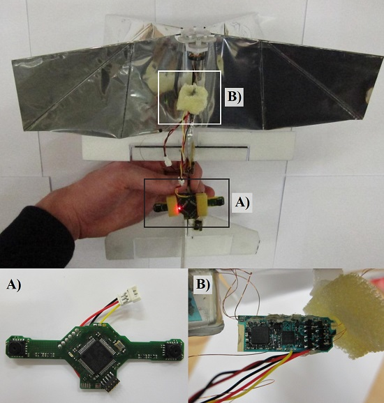
The DelFly (http://www.delfly.nl) is an FWMAV with two pairs of wings on top of each other. The DelFly Explorer, as shown in Figure 1a, is the newest version in the DelFly project [22]. It is based on the DelFly II, which was first demonstrated in 2007 [28]. The DelFly Explorer has a wingspan of 28 cm and a weight of 20 g.
There are three main differences between the DelFly Explorer and the older DelFly II. It is equipped with a -g autopilot board, which includes an ATmega328P-MLF28 micro-controller (Figure 1d). The board also features an MPU9050 IMU-sensor with three-axis gyroscopes, accelerometers and magnetometers. The autopilot board also contains a BMP180 absolute pressure sensor as the altitude sensor. The motor controller for the brushless motor is also integrated into the autopilot board to save weight. Finally, the autopilot features a two-way radio control and telemetry link using a CYRF69103 chip that allows transmission of onboard telemetry data while receiving radio control commands. The radio control is used during the development phase to switch back to manual flight.
Another difference between earlier DelFly versions [28] and the DelFly Explorer is the camera system. Previous designs were equipped with analog cameras and analog video transmitters, while image processing was done on the ground. The video stream could be captured by a ground station and used for vision-based control. The DelFly Explorer is equipped with two digital cameras that are used as a stereo vision system with a baseline of 6 cm. The camera images are not transmitted, but processed onboard using a 168-MHz STM32F405 micro-controller that performs the stereo vision processing (Figure 1c). The stereo vision board uses TCM8230 camera sensors.
Finally, some modifications on the airframe have been made for better flight performance. The weight increase to 20 g (compared to 17 g in previous versions) required some increase in thrust from the flapping wings. This was achieved by reducing the number of coil windings of the electric motor, which in turn increases the current and power for a given battery voltage. This comes at the cost of slightly reduced efficiency. Nevertheless, in this configuration, the DelFly Explorer can fly in slow forward flight for around 10 min. For better directional control, the DelFly Explorer is equipped with aileron surfaces. Figure 1e shows the definition of the body axes of the DelFly. The aileron surfaces provide a moment around the X-axis, which is referred to as rolling. However, due to the high pitch angle attitude of the DelFly Explorer in slow forward flight, a moment around the body X-axis mainly controls heading (see Figure 1b). Accurate control of this axis is therefore important. This is in contrast to previous DelFly designs where a vertical tail rudder was used for heading control. This rudder provides a yaw moment around the Z-axis, which gives indirect control of the heading through the vehicle bank dynamics. Both aileron surfaces in DelFly Explorer are actuated by a single servo. The tail of DelFly Explorer contains an elevator surface, which is also actuated by a servo. The elevator deflection regulates the pitch angle, and thereby the forward flight speed. All versions of DelFly have a stable slow forward flight with a center of gravity relatively far back. In DelFly Explorer, this is obtained by placing the relatively heavy stereo camera in between the main wing and the tail section. In this condition, DelFly is not stable at fast forward flight, but very stable in slow indoor flight. The maximum elevator deflection is kept small and is insufficient to transition to fast forward flight.
3. Vision and Control Algorithms
When using stereo vision as the basis for control, stereo matching is the most demanding part of the whole processing routine. Obtaining real-time stereo vision-based navigation onboard a very limited processor like the one on DelFly Explorer requires a very efficient algorithm. Based on the 32-bit processing speed of only 168 MHz and, even worse, the availability of only 196 kB of RAM, images are processed at a resolution of only 128 × 96 pixels.
The implemented stereo vision algorithm and the description of how the resulting disparity maps are used for control will further be discussed in this section.
3.1. Stereo Vision Algorithm
Stereo vision algorithms are extensively studied in the field of image processing. These algorithms can be divided into two types. They provide either sparse or dense disparity maps. Sparse methods can be more efficient, since only specific image features are selected and further processed. However, for the purpose of obstacle detection and avoidance, these algorithms have the disadvantage that the relation/connection between the feature points is missing. In other words, they provide more restricted information.
In this study, a slightly modified implementation of the method proposed by [29] is used. This local stereo matching algorithm focuses on the trade-off between accuracy and computational complexity. According to the Middlebury stereo benchmark [30], it is one of the most effective local stereo algorithms.
To ensure a real-time performance of at least 10 Hz, several modifications are applied. First, it is implemented such that the algorithm operates on individual image lines. This limits the amount of required memory. Furthermore, the stereo vision system has only access to the grayscale values by design. Namely, to merge both camera feeds into a single DCMI (Digital Camera Media Interface) input of the memory-limited micro-controller, the Altera MAX II CPLD (Complex Programmable Logic Device) replaces the color information of one image with the intensity of the other. The resulting image stream contains alternating 8-bit gray-scale values of both cameras.
The algorithm itself is also changed. The first difference is in the cost calculation. The work in [29] based it on the Sum of Absolute Difference (SAD) and the CENSUS transform, which is a non-parametric local transform used in visual correspondence. Instead, we use the SAD calculation only, which is further reduced to a one-dimensional window ( in our implementation). The permeability weight calculation is slightly changed. In our implementation, it is only based on the pixel intensity. Then, the exponent calculation is implemented using a look-up table for efficiency. As a smoothing factor, we use . Finally, the costs are aggregated based on horizontal support only to keep the algorithm line based. After aggregation, the disparity value corresponding to minimum pixel cost is selected. For more details about the method, the reader is referred to [29].
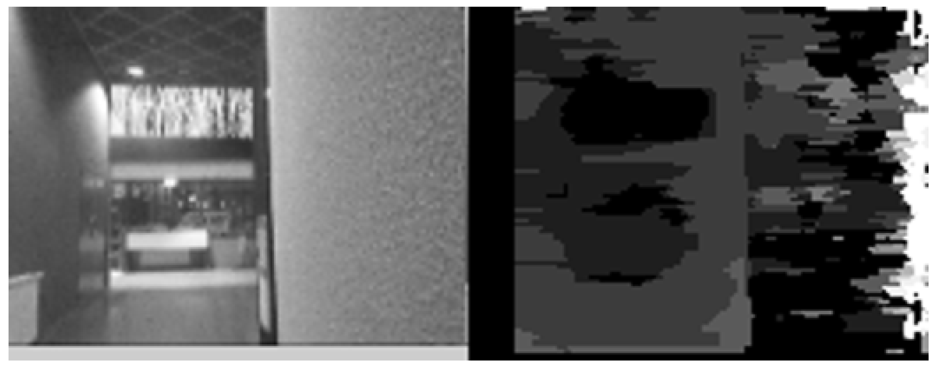
Figure 2 shows the result of our implementation on the Tsukuba image from the well-known Middlebury stereo benchmark. Note that there is a significant streaking effect because all calculations in our implementation are line-based. Figure 3 shows the result of this algorithm on real images of the corridor used in further testing. These images are taken by and processed by the DelFly Explorer stereo vision system. From these figures, it can be seen that our simplified version of [29] is still very effective at retrieving the overall depth structure.
3.2. Disparity Map Updating
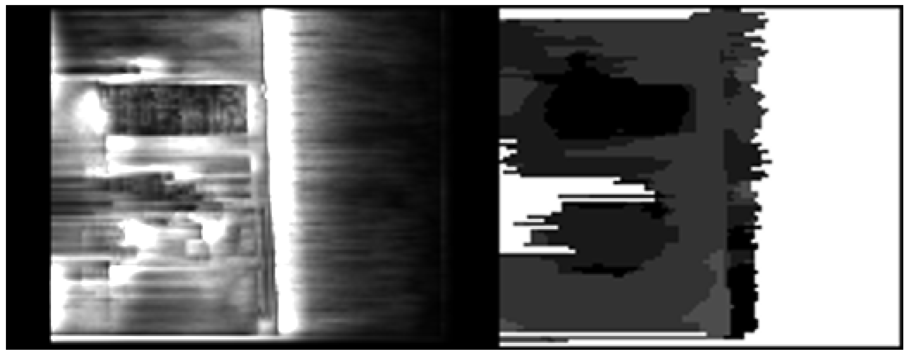
The disparity maps from the stereo vision algorithm are used directly for control purposes. Tests with the algorithm showed that the matching quality is very bad when the cameras are close to a wall with poor texture. This is illustrated in Figure 4, which shows an image of a corridor and the corresponding disparity map. In this case, the wall is particularly complex to process since the wall is curved. A solution to this problem is to use the matching certainty as a measure to detect image regions with very poor stereo correspondence. The matching certainty is defined as:
is the matching cost for a certain disparity. Only if the certainty c of a pixel is above a threshold , it is considered to be reliable. The disparity image is updated according to this uncertainty. For each image line, the algorithm checks which pixels, starting from both the left and right border, are regarded as unreliable. As soon as a reliable pixel is found, all disparities up to that point in the disparity image line are discarded. Figure 5 shows the reliability of all pixels (left) from Figure 4 and which pixels are regarded as uncertain based on . A second method is used to cope with wall regions that are considered to be reliable, but that are actually wrong. Since the matching performance of stereo vision algorithms relies on image texture, a simplified form of linear edge detection is used. Edge detection is based on the intensity difference of neighboring pixels:
in which is the intensity of a pixel and is the absolute difference in intensity in the x direction of two neighboring pixels. Only the difference in the horizontal direction is taken into account since it is already calculated for the permeability weight calculation in the stereo vision algorithm. Again, a threshold, , is used to define if a pixel difference corresponds to a line. The disparity map is updated in the same way as for the certainty measure.
3.3. Control Logic
The updated disparity map is used to define the control input. The focus of this work is on heading control of the DelFly Explorer. As described in Section 2, the heading is controlled by the aileron surfaces . In forward flight, these control surfaces are trimmed such that the DelFly flies in a straight line. Feedback from the gyroscopes stabilizes the heading angle of DelFly to counteract disturbances.
where p is the turn-rate along the body X-axis, is the desired turn rate and is the aileron trim command. The navigation control is then selected based on the simple rule that the DelFly should always fly in the direction where the disparity values are the smallest . A saturated P controller is used with gain :
This guides the DelFly in the visible direction where obstacles are furthest away. The advantage of this choice is that it works both with doors and corridors. Furthermore, when approaching an obstacle, the region next to the obstacle will have a lower disparity and guides the DelFly away from the obstacle. While this guidance rule is sufficiently simple to fit onboard smaller processors and is particularly effective to traverse corridors, it does have some failure cases. For instance, when the direction of minimal disparity is very close to the edge of an obstacle, it can fail to add sufficient clearance to the obstacle.
The aiming point is the point in the disparity map with the lowest disparity values. It is found by calculating the average position of all pixels that have a certain disparity value. Again, only the horizontal position in the image is taken into account. It is computed by counting how many times each disparity value occurs and what the average horizontal coordinate of this group of pixels is. Then, the lowest disparity value is found that occurs at least more than selected threshold . The average horizontal position of this group of pixels is selected as the aiming point. The control input is then defined as the difference between the coordinate of the aiming point and the center coordinate of the image divided by the horizontal field of view of the camera .
The stereo vision camera and the autopilot board are separate systems, as shown in Figure 1. The whole image processing routine, up to the calculation of the control input , is performed on the micro-controller of the stereo vision system. This signal is sent to the autopilot, which runs the gyroscope feedback from Equation (3) and drives the actuators.
4. Experiments
Several experiments were performed to test the effectiveness of the proposed navigation method. This section gives an overview of the tests and the results and ends with a discussion.
4.1. Flight through an Opened Door
Flying through an opened door has been tested in two different experiments. The first experiment has been conducted in a setup test environment as shown in the left image of Figure 6. Two walls have been placed such that a gap of 80 cm is left in between. The setup is placed inside a NaturalPoint OptiTrack motion tracking system consisting of twelve cameras. Only six cameras on one side could track the DelFly Explorer during the test, as the others were blocked by the walls in the setup. The OptiTrack system can deliver measurements with better than 3-mm precision.
During the tests, the DelFly Explorer is guided manually to a position in front of the artificial door. The operator then switches the system to autonomous flight mode, at which point the heading control is taken over by the autopilot. The DelFly was switched to autonomous navigation at a distance of about 2 m from the door. At closer distances, the DelFly would often turn away from the door and navigate to larger obstacle-free areas left or right of the test setup.
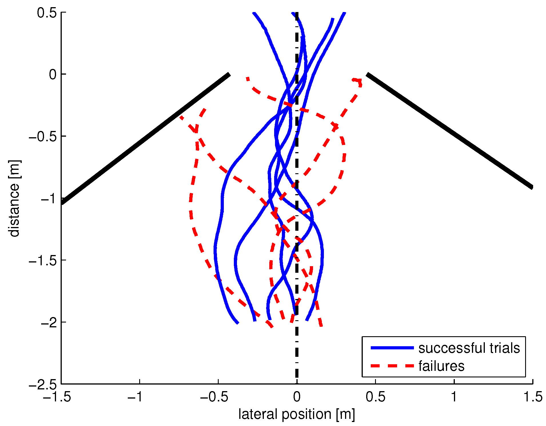
The flight trajectory results of this test are shown in Figure 7. The figure presents not only the successful trials, but also shows the trials where the DelFly hit one of the walls. These failure cases seem to occur because of several reasons. In three of the failure cases, the DelFly seems to aim at the edge of the wall. This can be compensated by aiming at a distant point with a minimum lateral offset of close-by points, but this is left to future work. Some of the failure cases, the trajectory shows some rapid turns. Although no onboard logging of the images could be performed aboard the 20-g robot, these are most likely due to stereo matching problems. More onboard memory and onboard processing are expected to improve this problem in the future. For the successful trials, the trajectories are relatively close to the middle line.
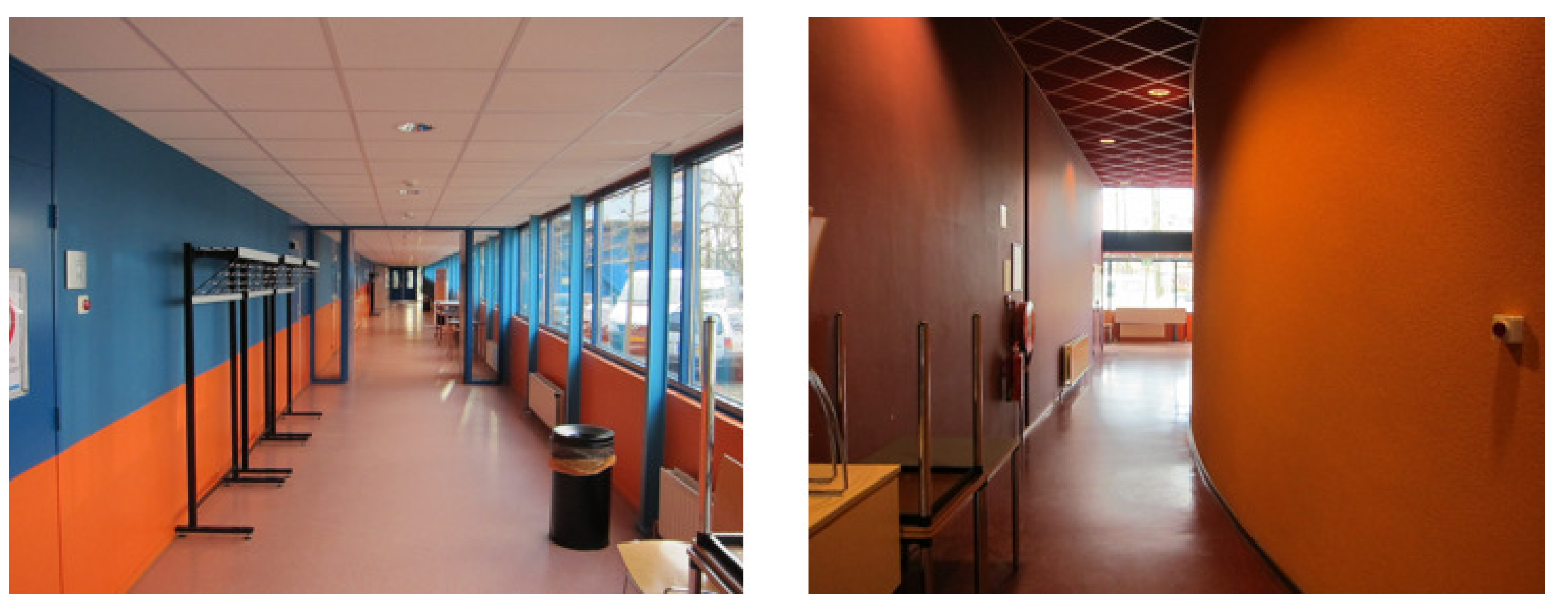
A similar test was performed using a regular office door as shown in the right image of Figure 6. In this case, the DelFly was able to go through the opened door ten times in a row. Since no external motion tracking system is available in this office, no ground truth data are available, but videos were made. The videos can be found in “Supplementary Materials” and online (https://www.youtube.com/playlist?list=PL_KSX9GOn2P8D8H266jec-0U3439vVwwU).
4.2. Flight through a Straight Corridor
Another experiment was conducted in the straight corridor shown in Figure 8. No modifications were made to the environment, nor was the algorithm tuned for any of the conditions. An example disparity map taken by the onboard camera in this corridor is depicted in Figure 3. The DelFly was able to follow the corridor nicely and most of the time traversed it up to the end. It could handle the glass windows on the right very well thanks to the many vertical construction elements and texture above and below. Halfway through the corridor, the DelFly also handled the slightly narrower passage successfully. However, when passing the rack full of jackets at the end, its reaction was to suddenly quickly turn towards it. It is believed that lack of resolution caused erroneous disparities at that point.
4.3. Flight through a Curved Corridor
The corridor as shown in the right image of Figure 8 was also used as a test environment for the corridor-following task. In many studies, a very structured and straight repetitive corridor is used. In contrast, this curved corridor with little texture misses important features such as vertical straight lines along the wall, as was believed to be a challenge.
Initial testing revealed that the stereo matching of the curved texture-poor wall is a challenge indeed. For this reason, the disparity map-updating procedures described in Section 3.2 was introduced. With this updated processing that takes uncertainty into account, the DelFly can follow even the textureless curved corridor successfully for long stretches. However, as was the case during tests in the straight corridor, the DelFly would also occasionally suddenly turn aside. In one case, it turned and entered an opened door on the side of the corridor. Finally, it was observed that the DelFly would often fly close to the wall that forms the inner side of the curved corridor.
4.4. Discussion
The presented test results show that the proposed method for autonomous navigation is effective for certain cases, but not for all situations that were tested. It was observed during post-flight analysis of the test from Section 4.1 that the aiming point can be very close to one of the posts of the door. This is influenced by the structure of the environment at the other side of the door. Better rules for determining the aiming point should be used to handle such cases. As suggested, aiming points could keep a minimal distance from high disparity close-by points.
Some mechanical issues were also observed with the very lightweight ailerons of the tiny flapping-wing robot. Large aileron deflections, for instance, could result in aileron overshoots. Due to the large aerodynamic load on the aileron in that situation, the actuating servo would have trouble turning it back. This results in significant overshooting of the desired heading and is believed to account for several of the failures. Limits on the aileron control inputs should be used to prevent this. Finally, the light DelFly is susceptible to drafts and turbulence in open doors and from air conditioning installations. While gyroscope feedback solves a large part of this, in some trials, the DelFly was seen to move sideways. This is not accounted for in the navigation yet.
Future work will also focus on controlling the forward speed of the DelFly. To allow rapid exploration with safe door traversal, a flight speed can be selected based on the proximity of obstacles. This can only be done within limitations imposed by the field of view of the camera. In the DelFly, 10 pitch up from slow forward flight can bring the vehicle to hover, while 10 pitch down can double its forward speed while maintaining a forward field of view. This will also contribute to more robust obstacle avoidance. Furthermore, it will be studied how the avoidance strategy from [19] can be combined with speed control. Finally, future work will also study the integration of height control.
5. Conclusions
In this paper, we present navigation experiments on an FWMAV that is equipped with an onboard stereo vision system. Based on real-time computed disparity maps, the best navigation direction is defined by searching the furthest point in the disparity map. By following this rule, the MAV is guided along obstacles, through doors and through corridors.
Experiments on different tasks and in different environments show that the method is effective at guiding the MAV in many cases. However, several cases were encountered where the current method produced the wrong control inputs, leading to unexpected behavior and crashes. In some cases, the aiming point was selected too close to borders of the door. In other cases, the low-resolution four-gram stereo vision system had too low resolution to properly detect the texture. Finally, some hardware issues and wind issues did play a role. Future work aims at solving these problems. Furthermore, the method will be expanded by integrating speed control based on obstacle proximity and by integrating height control.
Supplementary Materials
The following are available online at https://www.mdpi.com/2226-4310/5/3/69/s1: Video S1: Autonomous flapping wing micro robot corridor traversal.
Author Contributions
S.T., C.D.W., B.R. and G.d.C. conceived of and designed the experiments. S.T. performed the experiments. S.T. and G.d.C. analyzed the data. C.D.W. developed the stereo camera. S.T., C.D.W. and G.d.C. wrote the paper. S.T., C.D.W., B.R. and G.d.C. approved the final version of the manuscript.
Funding
This research received no external funding.
Conflicts of Interest
The authors declare no conflict of interest.
Abbreviations
The following abbreviations are used in this manuscript:
| CPLD | Complex Programmable Logic Device |
| DCMI | Digital Camera Media Interface |
| FWMAV | Flapping Wing Micro Air Vehicle |
| MAV | Micro Air Vehicle |
| SAD | Sum of Absolute Difference |
References
- Bachrach, A.; He, R.; Roy, N. Autonomous Flight in Unstructured and Unknown Indoor Environments; Escola de Mitjans Audiovisuals: Barcelona, Spain, 2009. [Google Scholar]
- Grzonka, S.; Grisetti, G.; Burgard, W. Towards a navigation system for autonomous indoor flying. In Proceedings of the ICRA 2009 International Conference on Robotics and Automation, Kobe, Japan, 18 May 2009. [Google Scholar]
- Huang, A.; Bachrach, A.; Henry, P.; Krainin, M.; Maturana, D.; Fox, D.; Roy, N. Visual Odometry and Mapping for Autonomous Flight Using an RGB-D Camera. In Robotics Research; Christensen, H., Khatib, O., Eds.; Springer Tracts in Advanced Robotics; Springer: Cham, Switzerland, 2017; Volume 100, pp. 235–252. [Google Scholar]
- Fallon, M.F.; Johannsson, H.; Leonard, J.J. Efficient scene simulation for robust Monte Carlo localization using an RGB-D camera. In Proceedings of the 2012 IEEE International Conference on Robotics and Automation (ICRA), St. Paul, MN, USA, 14–18 May 2012; pp. 1663–1670. [Google Scholar]
- Schmid, K.; Suppa, M.; Burschka, D. Towards Autonomous MAV Exploration in Cluttered Indoor and Outdoor Environments. In Proceedings of the RSS 2013 Workshop on Resource-Efficient Integration of Perception, Control and Navigation for Micro Air Vehicles (MAVs), Berlin, Germany, 24–28 June 2013. [Google Scholar]
- Shen, S.; Mulgaonkar, Y.; Michael, N.; Kumar, V. Vision-Based State Estimation and Trajectory Control towards High-Speed Flight with a Quadrotor. In Proceedings of the RSS 2013 Workshop on Resource-Efficient Integration of Perception, Control and Navigation for Micro Air Vehicles (MAVs), Berlin, Germany, 24–28 June 2013. [Google Scholar]
- Zufferey, J.C.; Floreano, D. Toward 30-gram Autonomous Indoor Aircraft: Vision-based Obstacle Avoidance and Altitude Control. In Proceedings of the 2005 IEEE International Conference on Robotics and Automation, Barcelona, Spain, 18–22 April 2005. [Google Scholar]
- De Croon, G.; Groen, M.; Wagter, C.D.; Remes, B.; Ruijsink, R.; van Oudheusden, B. Design, Aerodynamics, and Autonomy of the DelFly. Bioinspir. Biomim. 2012, 7, 025003. [Google Scholar] [CrossRef] [PubMed]
- Keennon, M.; Klingebiel, K.; Won, H.; Andriukov, A. Development of the Nano Hummingbird: A Tailless flapping wing micro air vehicle. In Proceedings of the 50th AIAA Aerospace Science Meeting, Nashville, TN, USA, 6–9 January 2012; pp. 6–12. [Google Scholar]
- Ma, K.; Chirarattananon, P.; Fuller, S.; Wood, R. Controlled Flight of a Biologically Inspired, Insect-Scale Robot. Science 2013, 340, 603–607. [Google Scholar] [CrossRef] [PubMed]
- De Croon, G.; de Clerq, K.; Ruijsink, R.; Remes, B.; de Wagter, C. Design, aerodynamics, and vision-based control of the DelFly. Int. J. Micro Air Veh. 2009, 1, 71–97. [Google Scholar] [CrossRef]
- Chen, C.L.; Hsiao, F.Y. Attitude Acquisition Using Stereo-Vision Methodology. In Proceedings of the IASTED Conference, Banff, AB, Canada, 6–8 July 2009. [Google Scholar]
- Baek, S.; Fearing, R. Flight forces and altitude regulation of 12 gram i-bird. In Proceedings of the IEEE RAS and EMBS International Conference on Biomedical Robotics and Biomechatronics, Tokyo, Japan, 26–29 September 2010; pp. 454–460. [Google Scholar]
- Hsiao, F.; Hsu, H.; Chen, C.; Yang, L.; Shen, J.F. Using Stereo Vision to Acquire the Flight Information of Flapping-Wing MAVs. J. Appl. Sci. Eng. 2012, 15, 213–226. [Google Scholar]
- Julian, C.; Rose, C.; Hu, H.; Fearing, R. Cooperative Control and Modeling for Narrow Passage Traversal with an Ornithopter MAV and Lightweight Ground station. In Proceedings of the 2013 International Conference on Autonomous Agents and Multi-Agent Systems, St. Paul, MN, USA, 6–10 May 2013. [Google Scholar]
- Hsiao, F.Y.; Lee, P.Y. Autonomous indoor passageway finding using 3D scene reconstruction with stereo vision. In Proceedings of the 2017 Computing Conference, London, UK, 18–20 July 2017; pp. 279–285. [Google Scholar]
- De Croon, G.; de Wagter, C.; Remes, B.; Ruijsink, R. Random sampling for indoor flight. In Proceedings of the International Micro Air Vehicle Conference, Braunschweig, Germany, 6–9 July 2010. [Google Scholar]
- De Croon, G.; de Weerdt, E.; de Wagter, C.; Remes, B.; Ruijsink, R. The appearance variation cue for obstacle avoidance. IEEE Trans. Robot. 2012, 28, 529–534. [Google Scholar] [CrossRef]
- Tijmons, S.; de Croon, G.; Remes, B.; Wagter, C.D.; Ruijsink, R.; van Kampen, E.J.; Chu, Q. Stereo Vision based Obstacle Avoidance on Flapping Wing MAVs. In Advances in Aerospace Guidance, Navigation and Control; Springer International Publishing: Heidelberg/Berlin, Germany, 2013; pp. 463–482. [Google Scholar]
- Baek, S.; Bermudez, F.G.; Fearing, R. Flight control for target seeking by 13 g ornithopter. In Proceedings of the International Conference on Intelligent Robots and Systems, San Francisco, CA, USA, 25–30 September 2011. [Google Scholar]
- Tijmons, S.; de Croon, G.; Remes, B.; Wagter, C.D.; Mulder, M. Obstacle Avoidance Strategy using onboard Stereo Vision on a Flapping Wing MAV. IEEE Trans. Robot. 2017, 33, 858–874. [Google Scholar] [CrossRef]
- Wagter, C.D.; Tijmons, S.; Remes, B.; de Croon, G. Autonomous Flight of a 20-gram Flapping Wing MAV with a 4-gram Onboard Stereo Vision System. In Proceedings of the 2014 IEEE International Conference on Robotics and Automation (ICRA), Hong Kong, China, 31 May–7 June 2014. [Google Scholar]
- Schmid, K.; Tomic, T.; Ruess, F.; Hirschmuller, H.; Suppa, M. Stereo Vision based indoor/outdoor Navigation for Flying Robots. In Proceedings of the 2013 IEEE/RSJ International Conference on Intelligent Robots and Systems, Tokyo, Japan, 3–7 November 2013. [Google Scholar]
- Briod, A.; Zufferey, J.C.; Floreano, D. Optic-Flow Based Control of a 46 g Quadrotor. In Proceedings of the International Conference on Intelligent Robots and Systems (IROS), Tokyo, Japan, 7 November 2013. [Google Scholar]
- Zingg, S.; Scaramuzza, D.; Weiss, S.; Siegwart, R. MAV Navigation through Indoor Corridors Using Optical Flow. In Proceedings of the 2010 IEEE International Conference on Robotics and Automation, Anchorage, AK, USA, 3–7 May 2010. [Google Scholar]
- Pasteau, F.; Babel, M.; Sekkal, R. Corridor following wheelchair by visual servoing. In Proceedings of the International Conference on Intelligent Robots and Systems, Tokyo, Japan, 3–7 November 2013. [Google Scholar]
- Faragasso, A.; Oriolo, G.; Paolillo, A.; Vendittelli, M. Vision-Based Corridor Navigation for Humanoid Robots. In Proceedings of the Conference on Robotics and Automation, Karlsruhe, Germany, 6–10 May 2013. [Google Scholar]
- De Croon, G.C.H.E.; Perçin, M.; Remes, B.D.W.; Ruijsink, R.; De Wagter, C. The DelFly: Design, Aerodynamics, and Artificial Intelligence of a Flapping Wing Robot, 1st ed.; Springer: Heidelberg/Berlin, Germany, 2016. [Google Scholar]
- Cigla, C.; Alatan, A. Information permeability for stereo matching. Signal Process. Image Commun. 2013, 28, 59–64. [Google Scholar] [CrossRef]
- Scharstein, D.; Szeliski, R. A taxonomy and evaluation of dense two-frame stereo correspondence algorithms. Int. J. Comput. Vis. 2002, 47, 7–42. [Google Scholar] [CrossRef]
Figure 1.
Overview of the DelFly Explorer. (a) shows the 28-cm wingspan 20-g FWMAV in detail; (b) shows the DelFly Explorer during slow forward flight and visualizes the high pitch angle at this speed; (c) shows a close-up of the four-gram stereo vision system. It uses a Complex Programmable Logic Device (CPLD) to merge images and an STM32F4 to process the images; (d) shows a close-up of the 0.9-g autopilot board; the autopilot uses an 8-bit micro-controller and MPU9050 IMU; (e) shows the definition of the body axes of the DelFly.

Figure 2.
Tsukuba image from the Middlebury stereo benchmark and the resulting disparity map from our simplified implementation of [29].
Figure 2.
Tsukuba image from the Middlebury stereo benchmark and the resulting disparity map from our simplified implementation of [29].
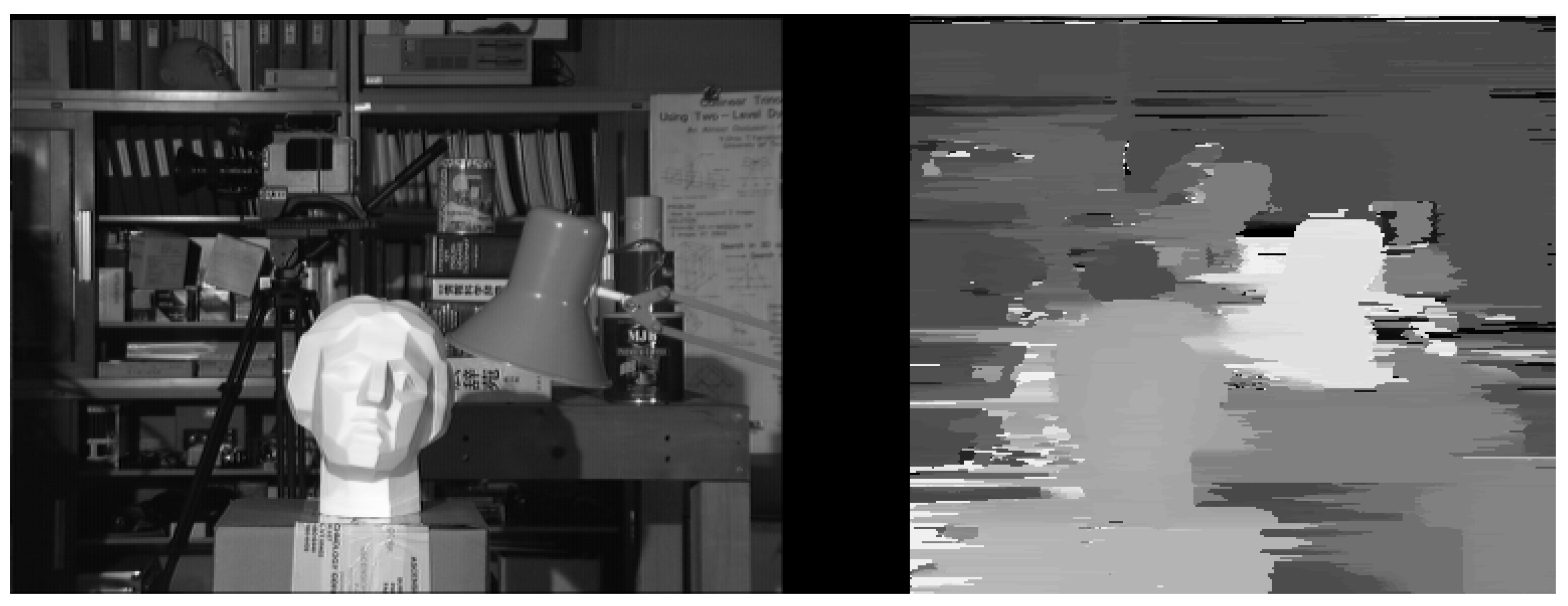
Figure 3.
Result of the implemented stereo vision method (based on [29]) on images of a corridor, taken by the DelFly Explorer stereo vision camera.
Figure 3.
Result of the implemented stereo vision method (based on [29]) on images of a corridor, taken by the DelFly Explorer stereo vision camera.
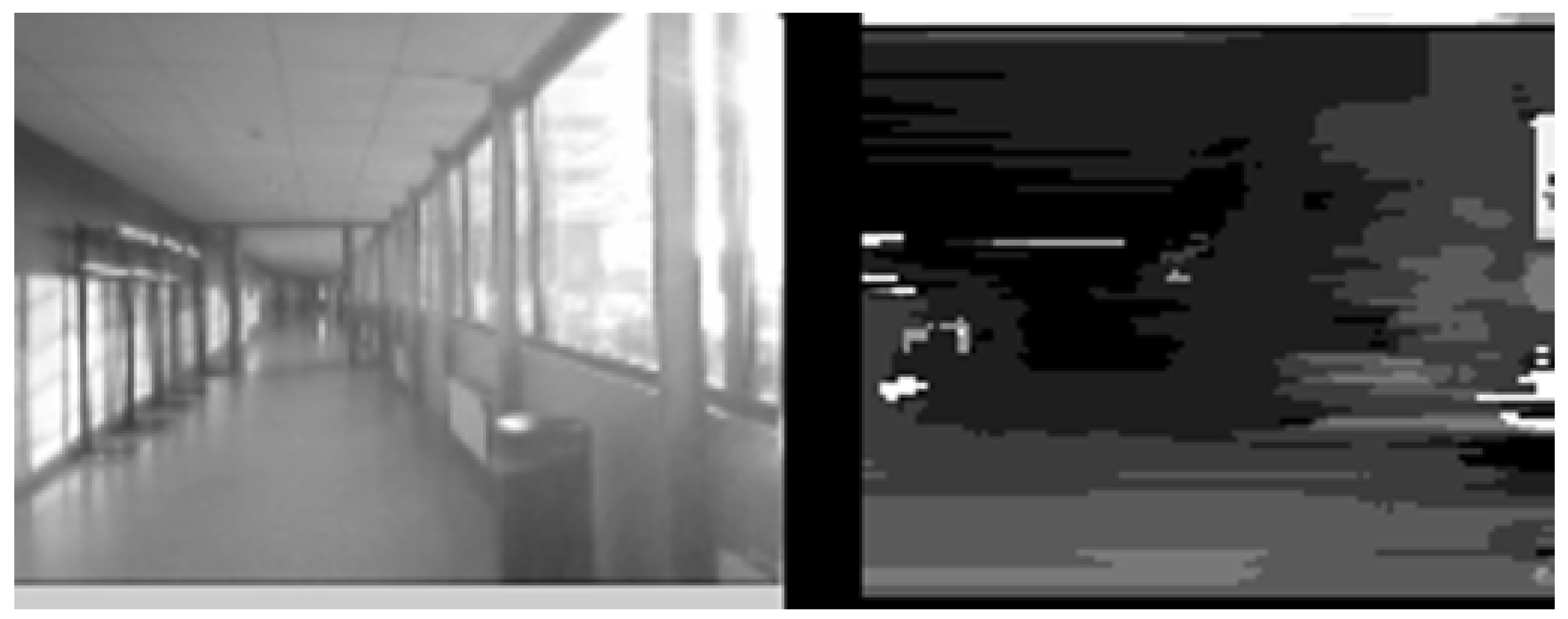
Figure 4.
Result of the implemented stereo vision method (based on [29]) on images of a corridor with a curved wall with little texture on the right side. The disparity map gives a poor result on the right side.
Figure 4.
Result of the implemented stereo vision method (based on [29]) on images of a corridor with a curved wall with little texture on the right side. The disparity map gives a poor result on the right side.

Figure 5.
The certainty map from the image in Figure 4 is shown on the left. The right image shows which border pixels are discarded because of a low certainty (indicated as white).
Figure 5.
The certainty map from the image in Figure 4 is shown on the left. The right image shows which border pixels are discarded because of a low certainty (indicated as white).

Figure 6.
Experimental setup for flight tests with an opened door on the left. The gap between the black walls is 80 cm. The right image shows a real door used for testing.
Figure 6.
Experimental setup for flight tests with an opened door on the left. The gap between the black walls is 80 cm. The right image shows a real door used for testing.
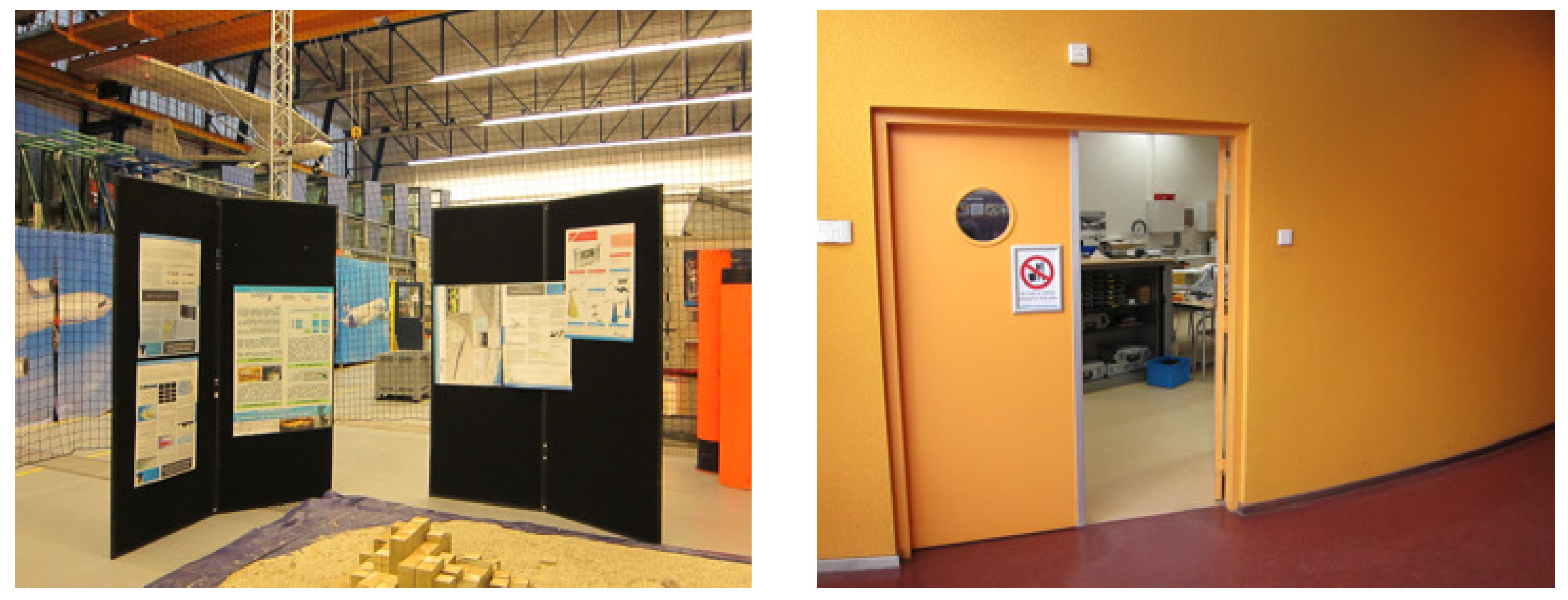
Figure 7.
Ground truth data of flight trajectories from tests where the DelFly was intended to fly through a simulated ‘door’ inside a motion tracking flight arena. The door is formed by two walls, indicated by the thick black lines on the side. The width of the door opening is 80 cm (see the left image in Figure 6). The DelFly starts each trial around the −2 m line. The vertical line indicates the middle line. Five successful trials are depicted and four failures. In three failures, the navigation would aim too close to the edge of the door. In one case, a bad detection or lack of texture is expected to have played an important role.

© 2018 by the authors. Licensee MDPI, Basel, Switzerland. This article is an open access article distributed under the terms and conditions of the Creative Commons Attribution (CC BY) license (http://creativecommons.org/licenses/by/4.0/).
Share and Cite
MDPI and ACS Style
Tijmons, S.; De Wagter, C.; Remes, B.; De Croon, G. Autonomous Door and Corridor Traversal with a 20-Gram Flapping Wing MAV by Onboard Stereo Vision. Aerospace 2018, 5, 69. https://doi.org/10.3390/aerospace5030069
AMA Style
Tijmons S, De Wagter C, Remes B, De Croon G. Autonomous Door and Corridor Traversal with a 20-Gram Flapping Wing MAV by Onboard Stereo Vision. Aerospace. 2018; 5(3):69. https://doi.org/10.3390/aerospace5030069
Chicago/Turabian StyleTijmons, Sjoerd, Christophe De Wagter, Bart Remes, and Guido De Croon. 2018. "Autonomous Door and Corridor Traversal with a 20-Gram Flapping Wing MAV by Onboard Stereo Vision" Aerospace 5, no. 3: 69. https://doi.org/10.3390/aerospace5030069
Note that from the first issue of 2016, this journal uses article numbers instead of page numbers. See further details here.