1. Introduction
Humans have been dreaming of building an airplane that can do “substantially everything that a bird can do in the air”, as revered New York University aeronautical engineer Alexander Klemin described, that can take off, land and hover anywhere like a helicopter and also fly as fast as a fixed-wing plane. Many efforts has been made so far, but designing a machine that combines the agility of a helicopter with the speed and range of a fixed-wing aircraft have proven difficult, as shown by the example of the V-22 Osprey, whose history has been plagued by delays, technical problems, and orders of magnitude leaps in cost overruns. The Osprey and the Sikorsky X2 compound helicopter can fly faster than conventional helicopters, but both made significant aerodynamic compromise to hovering efficiency or range. Fixed-wing vertical takeoff and landing (VTOL) airplanes, such as the AV-8 Harrier, the F-35B Lightning II, and the Russia Yak-38 Forger, can hover for only a short time, at the cost of range, efficiency and useful load.
There are four types of successful and practical VTOL aircraft so far, which include helicopters, vectored jet aircraft, tiltrotors and ducted lift fan aircraft. These aircraft provide solutions to this problem, but also have some disadvantages. The lift fan concept was proposed for S/VTOL in the 1960s. It was first implemented in the jet powered experimental aircraft Ryan GE XV-5 with a fan-in-wing configuration [
1]. Many experimental investigations have been conducted [
2,
3,
4]. The core engines of the Ryan XV-5 provided a total thrust of 5300 pounds in forward flight mode, but could generate a total lift thrust of 16,000 pounds via the lift fans in hover mode [
5]. Using the lift fans provided a 200% increase in the total thrust when compared to the jet engine thrust alone, a clearly advantageous feature for vertical takeoff and landing aircraft. Besides the fan-in-wing, the fan-in-fuselage concept has also been successfully applied in the Lockheed Martin F-35B joint strike fighter [
6]. Compared to conventional VTOL aircrafts, lift fan aircraft fly faster and require minimum ground preparation, without high discharge velocity and high surface temperatures to cause ground erosion and reingestion of hot gases which causes the lift engines to stall and lose lift [
7,
8,
9]. Without exposed rotor, lift fans are also safer than helicopters and tiltrotors. The drawback of lift fans is that they add dead weight when not used in cruise flight.
No matter the fan-in-wing or the fan-in-fuselage configurations, the sizes of the lift fans are limited due to the constraints of the fuselage and wing sizes. Because of the small size, all the lift fans thus far are high disc loading in order to provide sufficient lift. According to the momentum theory of ducted fans [
9,
10], high disc loading requires high power, thus leading to lower lift efficiency (power loading). To increase the lift efficiency, the fan area has to be increased to achieve low disc loading.
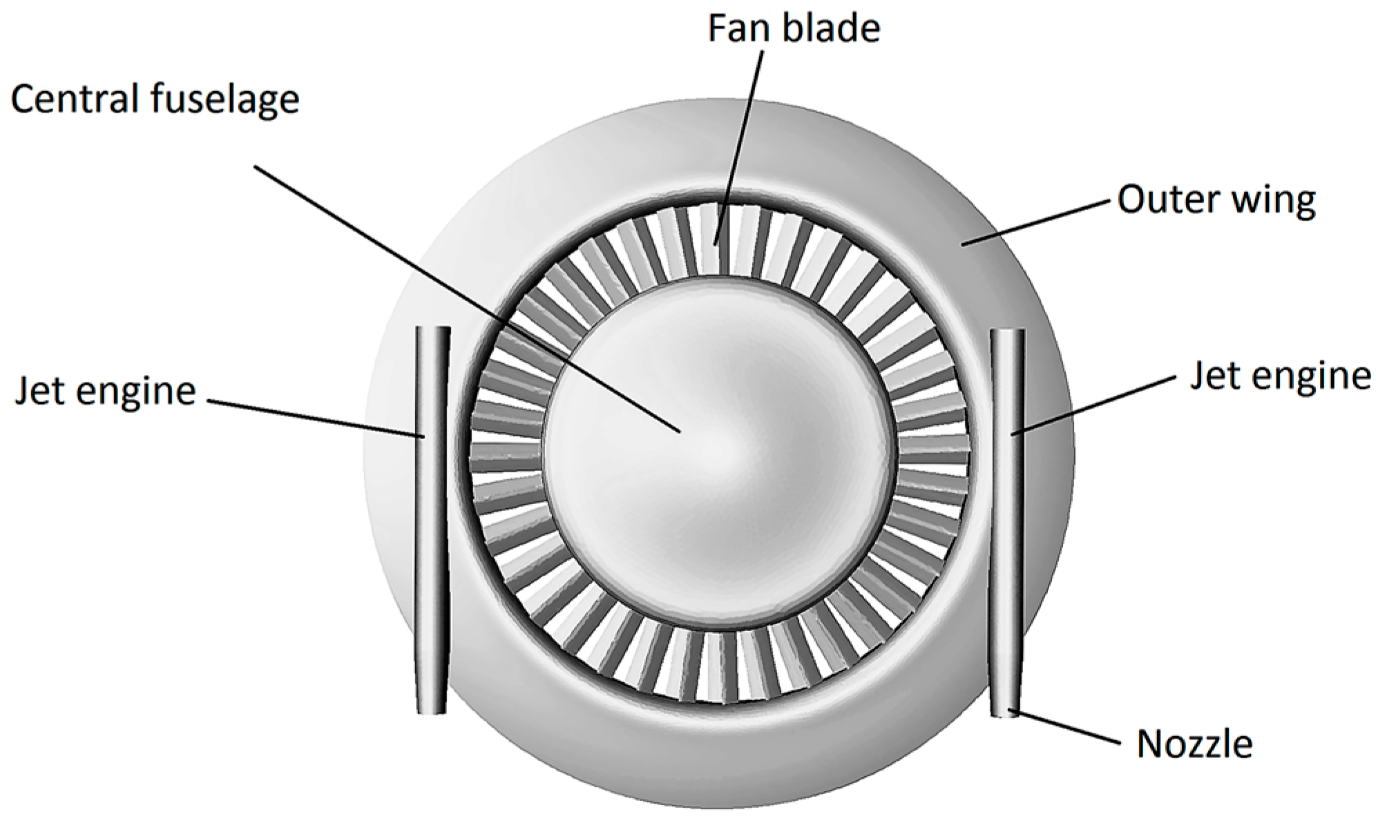
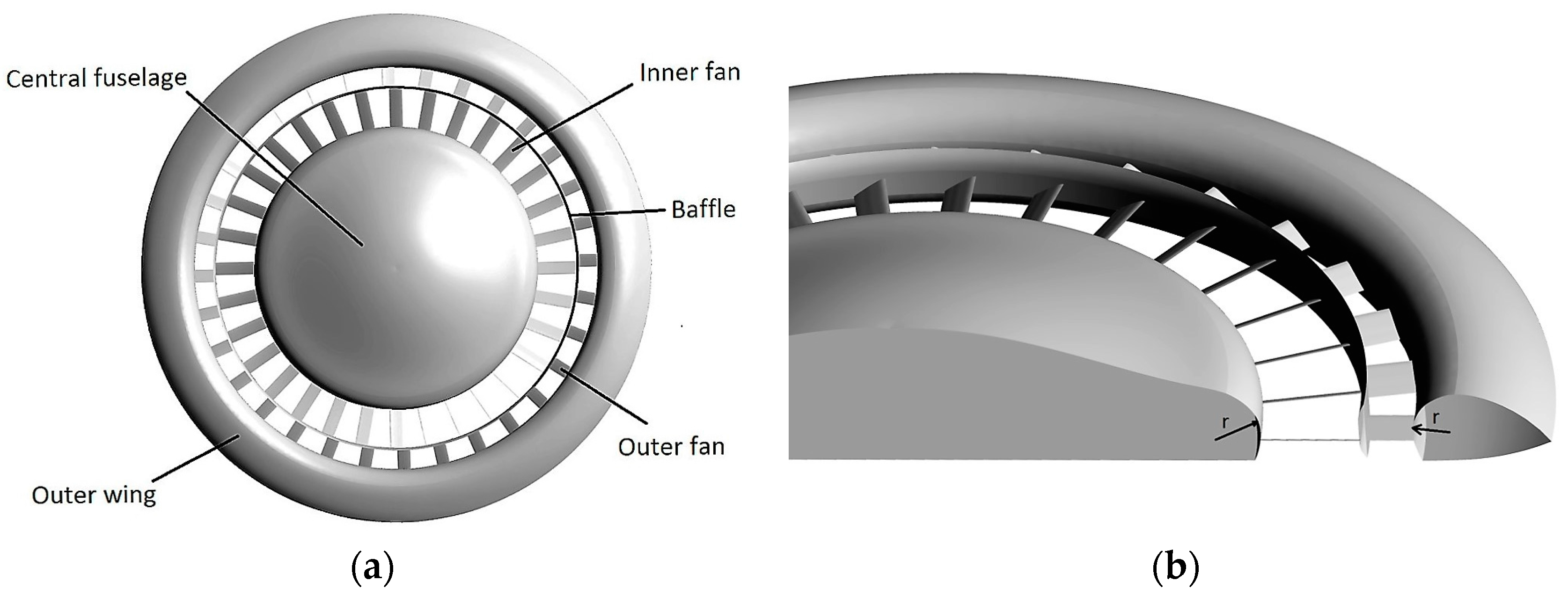
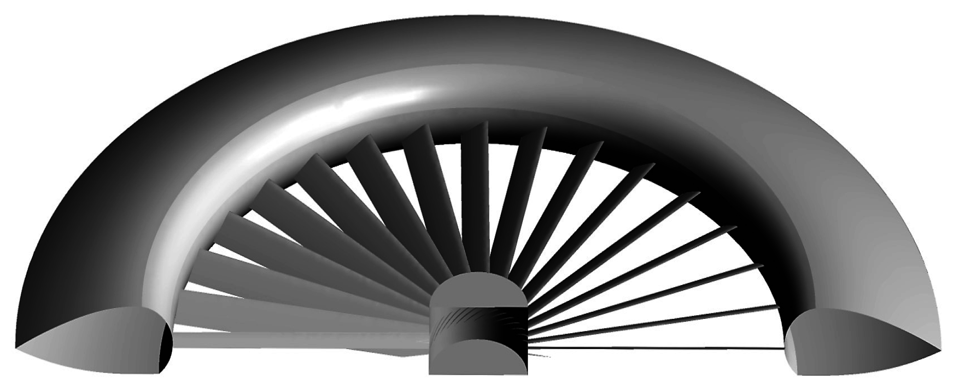
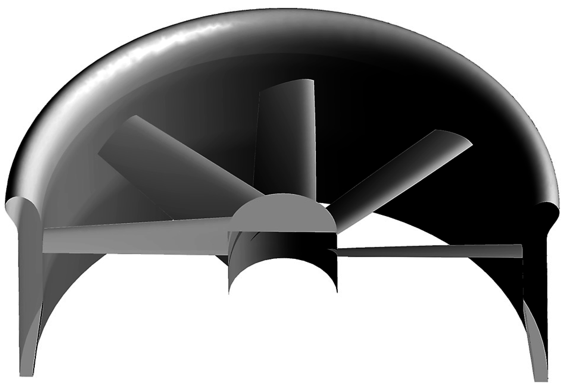
We proposed an annular lift fan concept with a central fuselage in the previous study to solve this problem [
10] (
Figure 1). The annular duct around the fuselage can greatly increase the lift fan area to achieve low disc loading and can also be easily shut off by shutters and louvers during cruise flight to provide aerodynamic lift and reduce drag. Because only half of the lift is generated by the fan (the other half is by the duct), the fan blades do not need to be very strong, thus can be made thin, narrow, hollow and of non-metal materials to reduce the dead weight. When the annular duct is closed, the occupied volume becomes part of ring wing in cruise flight. According to the computational fluid dynamics (CFD) simulation results [
10], the annular lift fan aircraft with the same size of the Apache rotor can have higher lift efficiency in a hover and may fly much faster than helicopters in a cruise based on the aerodynamic drag predictions.
The configuration of the annular lift fan system was explored in the previous study but not optimized [
10]. In this study, we focused on the optimization of parameters of the annular lift fan system for hovering efficiency.
Although there are theories in ducted fan design [
7,
9,
11], the calculation methods are far from satisfying the requirements of the industry. As a result of advances in CFD, many aerodynamic researches have moved in the branch of CFD, which is more affordable, practical, systematic and reliable [
12]. There are studies to numerically and experimentally investigate the aerodynamic characteristics of ducted fans in recent years [
1,
13,
14]. Thouault et al. studied the transition characteristics of a fan-in-wing configuration in wind tunnel and compared the CFD results with the experimental data [
1]. Akturk and Camci investigated the effects of tip clearance flow on aerodynamic performances of a ducted fan used in VTOL unmanned aerial vehicles and validated the numerical simulations with experimental data [
13]. These researches not only demonstrate detailed flow field analysis but also provide valuable experimental data for others to validate the computational simulations of ducted fan.
In the present investigation, a computational method was used to explore the effect of blade geometry, number of blades, and duct inlet lip shapes, etc., on the hovering efficiency of the annular lift fan system and to optimize the parameters for the best hovering performances.
5. Results
This section presents the numerical results obtained through simulations for various blade and inlet lip configurations. The figure of merit was calculated from ideal power and the actual power. The ideal power was calculated based on momentum theory [
9]:
where
T is the total thrust;
A is the fan area; σ is the duct diffusion ratio;
is the density of air,
= 1.225 kg/m
3.
The duct diffusion ratio σ was calculated from the fan thrust and the total thrust:
The actual power was calculated according to the moment of the fan and the rotational speed:
where
rF together is the moment, which can be obtained directly from simulation result; ω (rad/s) and
n (rpm) are the rotational speed.
The figure of merit was calculated:
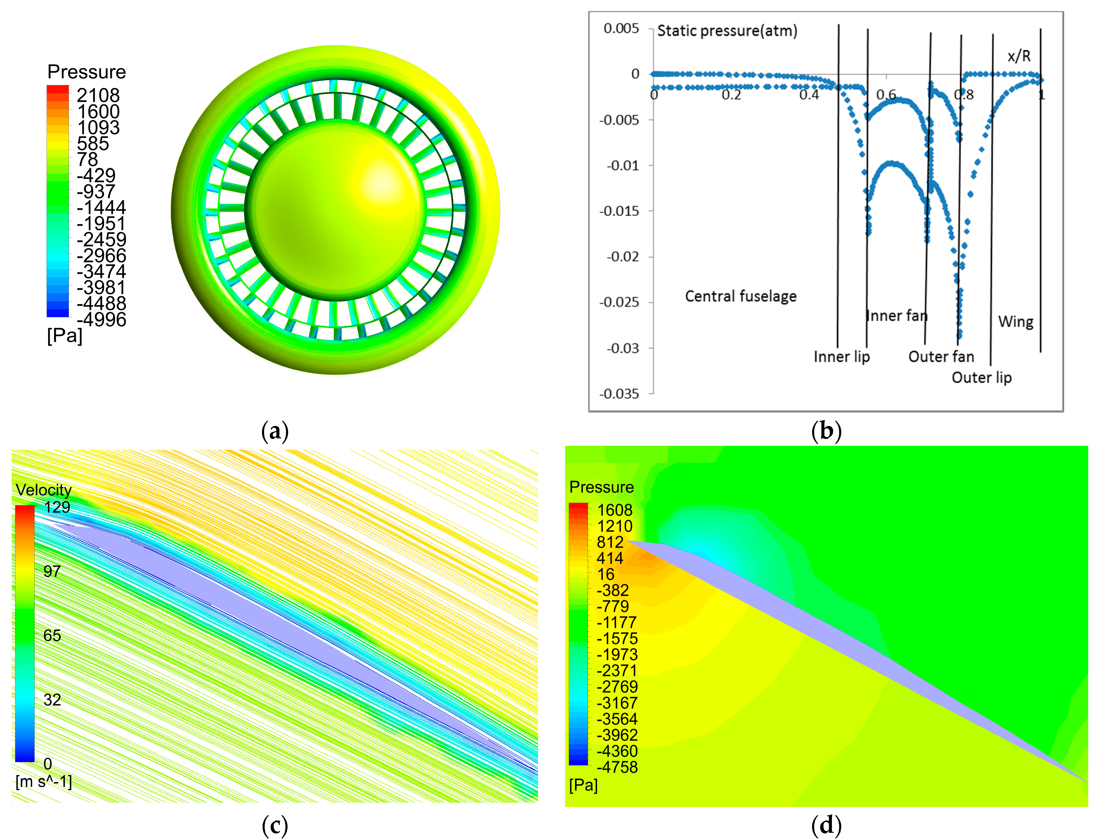
The pressure contour on the top surfaces of the vehicle and pressure distribution in the central plane are shown in
Figure 6. Low pressure can be seen on the fans and duct inlet lips. With the specific blade lengths, the torque was eliminated when the two fans rotated at the same contrary speed. The thrusts of the inner fan and outer fan were close, about 25 and 23 kN. The total thrusts were maintained at 10,433 kg (102,243 N) with disc loading of 138.5 kg/m
2 in all the simulations. The thrust was maintained by changing the rotational speed of fans. The σ varied from 0.9 to 1.10 with the ideal powers around 1600–1800 kw. The actual powers ranged from 2300 to 2750 kw with the rotational speeds changed from 120 to 190 rpm.
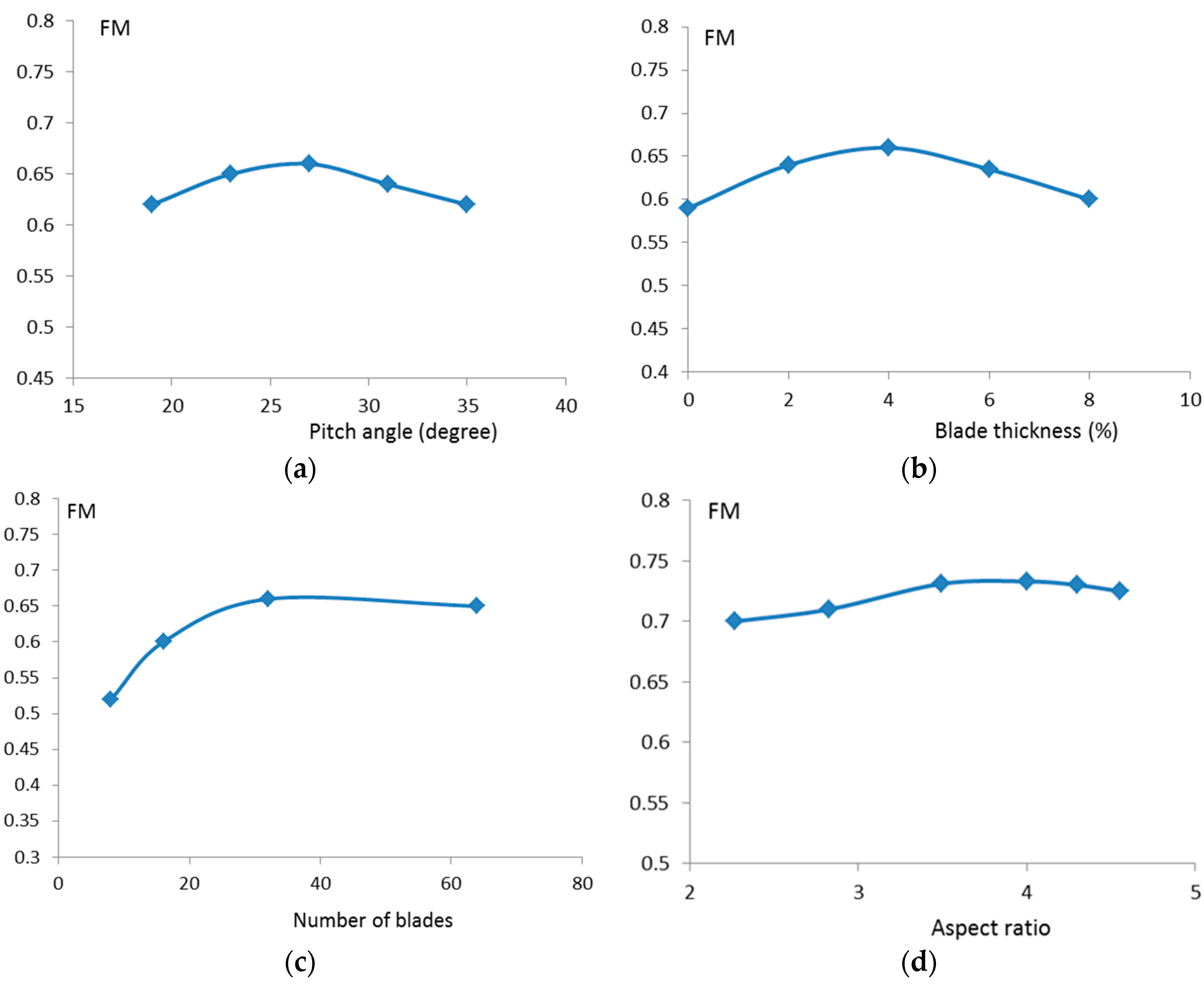
The simulations started from the baseline model with blade pitch angle of 27°, thickness of 4% chord length, aspect ratio of 2.27, and 32 blades. The effect of blade pitch angle on the figure of merit is shown in
Figure 7a. It is clear that the pitch angle of 27° produced the maximum FM with the fan rotational speed of 137 rpm. This angle is higher than that of a helicopter rotor because of the higher velocity of inflow induced by ducted fan.
With the pitch angle of 27°, the role of blade thickness in the figure of merit is shown in
Figure 7b. The thickness of 4% of chord length provided the best performance. This thickness is much thinner than a rotor blade, but is close to the tip thickness of a conventional ducted fan or propeller blade.
The number of blades also plays a role in the hovering efficiency. As shown in
Figure 7c, 32 blades generated the optimal result. More than 32 blades reduced the figure of merit, probably because too many blades increase the wet area and friction drag. Too few blades not only reduced the efficiency, but also increased the unsteadiness of the induced flow. This conclusion is only valid for very large ducted fans. For smaller ducted fans, such as the diameter around or less than 2 m, 3 or 4 blades work better.
The shape of inlet lip plays an important role in improving hovering efficiency.
Table 2 shows, when the radius of curvature of inlet lip
Rlip increased from 2.5% to 4.7%, the figure of merit increased from 0.665 to 0.704. This result is consistent to other’s observation that larger inlet lip radius promotes hover performance [
7,
24]. However,
Rlip is constrained by the depth of duct because the duct cannot be very thick in order to reduce the aerodynamic drag in cruise flight. The
Rlip is also constrained by the width of outer wing, but this is not a problem for a fin-in-wing configuration because the outer wing is usually wide enough. However, this is a problem for a shrouded fan because the thickness of shroud is also limited.
Figure 7d shows the effect of blade aspect ratio or chord length on the performance of the annular lift fan. Reducing the blade chord length almost half to the aspect ratio of 3.5~4.0 further increased the figure of merit to 0.733. This figure is as high as 0.73 of the two-stage fans in the previous study [
10]. The two-stage fans use counter rotating upper fan and lower fan to eliminate swirl loss and increase hover efficiency. For the single-stage fans, without the elimination of swirl loss, high efficiency was still achieved due to the improved inlet lips. Because the two-stage fans occupied much of the duct volume, the radii of inlet lips could only be small. For the single-stage fans, more duct space was saved for larger inlet lips, so the improvement in efficiency offset the swirl loss to achieve the same figure of merit as the two-stage fans. If the swirl loss of the single-stage fans could be further reduced by a stator, the figure of merit would be higher. However, the efforts to reduce the swirl loss always lead to strong interactions between the rotor and stator and result in oscillation and vibration of the aircraft in transition, so the number of stator blades cannot be many and the improvement of FM is very limited.
With the aspect ratio of 4.0 (chord length 0.5 m), taper or twist of blades did not further increase the figure of merit. Twist of blades deteriorated the performance. The role of taper and twist for an annular fan was not as important as for a circular lift fan probably because the annular fan is only equivalent to the peripheral 28% part of a circular fan. Even for a conventional circular fan, taper and twist of this part are relatively small.
With the higher aspect ratio, further changing blade pitch angle, the number of blades, or blade thickness did not further increase FM. Increasing the length of diffuser definitely would improve FM, but the increase is seriously restricted by the depth of duct. The increase of length of diffuser must lead to the decrease of Rlip, so the improvement is very limited.
Therefore, the maximum figure of merit that could be achieved by the annular lift fan was 0.733 (σ = 1.03, Pactual = 2293 kw, 137 rpm), with power loading 4.50 kg/kw at disc loading 138.5 kg/m2.
Compared to the numerical simulation results of a 10-m 32-bladed conventional circular lift fan with the same airfoil (4% thickness, chord length 0.5 m), the same fan area (75.3 m
2), the same disc loading (138.5 kg/m
2), the same duct depth (1 m), the same duct inlet lip shape and outer wing width (2.5 m) (
Figure 8), the highest figure of merit achieved was 0.751 (σ = 1.07,
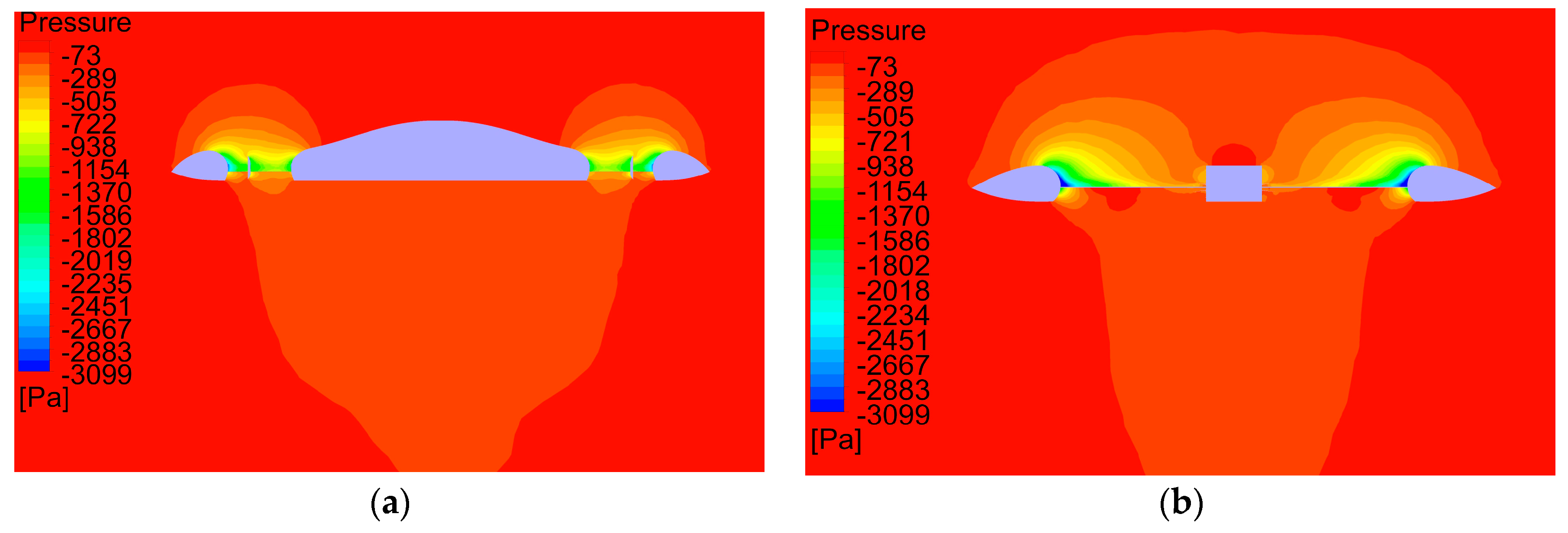
Pactual = 2187 kw, 203 rpm). The circular lift fan seems more efficient than the annular lift fan. This is probably because of the low pressure underneath the central fuselage of the annular fan as shown in
Figure 9a. The low pressure caused the fuselage to generate a net negative lift. The hub of circular fan is much smaller than the fuselage, so it generated much smaller negative lift (
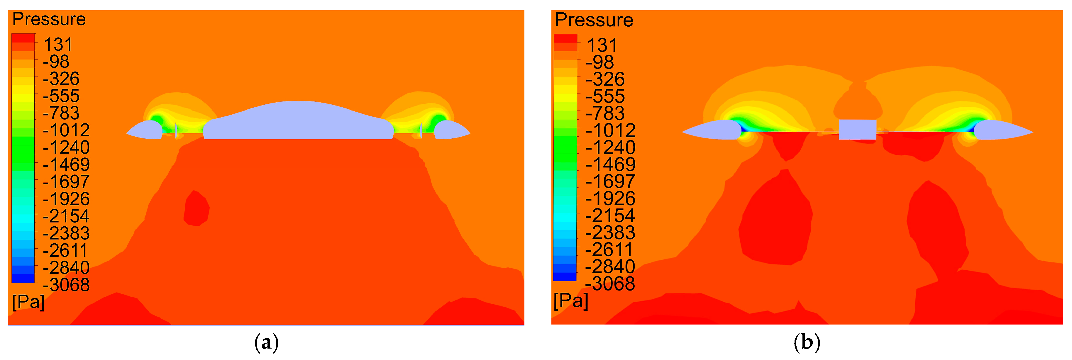
Figure 9b), thus this makes the circular fan more efficient. However, when the aircraft is close to the ground, the ground effect will play an important role. As shown in
Figure 10a, under the strong ground effect, the pressure underneath the fuselage of the annular lift fan aircraft became positive, producing a net positive lift, while the ground effect on the circular fan was very weak (
Figure 10b). When the distance between the aircraft and the ground was 10 m, the annular lift fan aircraft could achieve the figure of merit of 0.832 (σ = 1.10,
Pactual = 1928 kw, 119 rpm), much higher than 0.749 (σ = 0.87,
Pactual = 2420 kw, 200 rpm) of the circular lift fan. The high pressure was generated beneath the central fuselage because the exit flow from the annular duct enclosed the space between the ground and the bottom of fuselage, while the hub of circular fan was too small to produce significant lift and the interactions between the high pressure and the fan blades somehow reduced the lift of the duct and the figure of merit. The power loading of 5.2 kg/kw for the annular lift fan under the ground effect is much higher than 4.2 kg/kw for the circular lift fan.
Even if a large circular lift fan may be more efficient than the annular lift fan in hover, it is difficult to lay out the fuselage for such an aircraft with such a large fan. For an aircraft with a plurality of smaller circular fans around a central fuselage, other problems such as increased complexity may arise.
In practice, for most modern helicopter rotors, FM values of 0.7 and 0.8 represent a good hovering performance [
25], thus the FM of 0.733 of the annular lift fan is good enough for general aviation. In addition, the annular lift fan only works during VTOL when it is close to the ground, so the actual FM can be as high as 0.832.
The parameters of optimal annular lift fan can be summarized in
Table 3.
The improvement of airfoil with smooth leading edge may possibly further increase the maximum FM, but as the FM has been already high, the improvement will be limited and is not within the scope of this present investigation.
The optimized narrow and thin blades not only save space in the duct for larger Rlip of inlet lip, longer diffuser, for stator and struts, but also reduce the dead weight of fan. As the fan is tip driven by engines incorporated in the outer wing, the blade tips are fixed in the duct wall. The fan becomes strong and can be made of non-metal material to reduce the dead weight.
The optimized annular lift fan aircraft also has lower momentum drag and nose up pitching moment in transition [
15], due to the reduced chord length and width of outer wing.
6. Conclusions
Numerical simulations were conducted on an annular lift fan aircraft to investigate the effects of different parameters on the performance of hovering. The roles of pitch angle, thickness, chord length, number of blades, and shape of inlet lip were explored. The simulations were carried out with disc loading of 138.5 kg/m2 and duct depth of 1 m based on k-ω SST turbulence model.
The simulation results showed the pitch angle of 27°, thin blade with the maximum thickness of 4% chord length, high aspect ratio of 3.5~4.0 produced the highest FM. The number of blades was also important. Too few blades for a large fan led to deteriorated and unstable performance, but too many blades also reduced efficiency. About 32 blades was the best choice. Twist of blades deteriorated the performance. Taper of blades did not improve the efficiency.
The radius of duct inlet lip played a key role in hovering efficiency. Rlip should be as large as possible to ensure high figure of merit, but it was constrained by the depth of duct and width of outer wing. For a conventional ducted fan, Rlip is primarily constrained by the thickness of shroud. For the fan-in-wing configuration, Rlip is primarily constrained by the depth of duct. For the same reason, the length of diffuser exit is constrained for fan-in-wing, while it is usually not so constrained in the case of shrouded fans because the shroud is usually long enough. The maximum figure of merit achieved by the annular lift fan was 0.733 in hover, with power loading of 4.50 kg/kw.
The annular lift fan was less efficient than the circular lift fan of the same disc area in hover due to the low pressure beneath the central fuselage, but the annular lift fan was more efficient when close to the ground due to the ground effect and the high pressure beneath the fuselage. When the distance from the aircraft to the ground was 10 m, the maximum FM achieved by the annular lift fan was 0.832, with power loading of 5.2 kg/kw.


