
Thermal-Aeroelastic Investigation of a Hypersonic Panel Vibration Based on a Developed MMC Method

1
School of Mechanics and Aerospace Engineering, Dalian University of Technology, Dalian 116023, China
2
State Key Laboratory of Structural Analysis, Optimization and CAE Software for Industrial Equipment, Dalian University of Technology, Dalian 116023, China
3
Advanced Technology for Aerospace Vehicles of Liaoning Province, Dalian University of Technology, Dalian 116023, China
4
Department of Mechanical Engineering, College of Engineering, University of Canterbury, Christchurch 8041, New Zealand
*
Author to whom correspondence should be addressed.
Aerospace 2024, 11(3), 241; https://doi.org/10.3390/aerospace11030241
Submission received: 8 January 2024
/
Revised: 5 March 2024
/
Accepted: 15 March 2024
/
Published: 19 March 2024
(This article belongs to the Section Aeronautics)
Abstract
:Hypersonic vehicles or engines usually employ complex thermal protecting shells. This sometimes brings multi-physics difficulties, e.g., thermal-aeroelastic problems like panel flutter etc. This paper aims to propose a novel optimization method versus thermal dynamic influence on panel vibration. A traditional panel structure was modelled and analyzed. After analyzing its dynamic characteristics of panel flutter, thermal effects were also included to propose thermal-aeroelastic analysis results of the present hypersonic panel. Then, a MMC (Moving Morphable Component) method was proposed to suggest dynamic optimization for such panel structures. The proposed method can provide arbitrary frequency control result in order to suggest a newly generated panel structure. Based on the optimal structures, dynamic analysis was presented again to verify the effectiveness of the optimization method. So aero-thermo-dynamic characteristics of the optimal panel structures could be investigated. It can be seen that the computational results presented significantly improved panel flutter results. The proposed dynamic optimization method can be employed for the design of panel structures versus high combustion temperatures or hypersonic aerodynamics.
1. Introduction
In recent years, hypersonic vehicles have attracted the attention of researchers for their extremely fast flight speeds, but hypersonic vehicles also face many problems during flight, such as the panel flutter problem. This problem may be more pronounced in the thermal environment generated by hypersonic flights. Panel flutter is a self-excited vibration behavior of the panel structure under the combined effect of aerodynamic, inertial and elastic forces. When panel flutter occurs, it can cause severe vibration of the panel leading to failure. Therefore, some significant works have presented investigations on the aeroelastic optimization of panels.
Wang et al. [1] proposed an energy method based on Galerkin method and a two-degree-of-freedom reduced-order model that can be used in the calculation of panel flutter. The aerodynamic forces are applied to structure by first-order piston theory. Zhang et al. [2] investigated the flutter characteristics of a nonlinear spring-supported composite Panel. The aerodynamic forces are calculated by the third piston theory, and the structural equations of motion are obtained by von Karmen’s nonlinear theory. Since the piston theory assumes that the perturbation at each point of the airfoil propagates in the direction of that point and ignores the interaction of the airfoil points, some works were presented to use other aerodynamic theories to calculate the panel flutter. Serafim et al. [3] used unsteady potential flow aerodynamics to calculate flutter characteristics of panel at subsonic, transonic and supersonic conditions.
As the flight velocity of the vehicle is increasing, the panel will be subjected to a high temperature environment; many studies [4,5] were presented on the panel flutter problem in the thermal environment. Ye et al. [6] studied the effect of temperature-dependent material properties on the buckling and flutter characteristics of a heated panel. The results show that the temperature-dependent material parameters have a very significant effect on the buckling and flutter characteristics of the panel. Chen et al. [7] investigated the flutter characteristics of angle tow composite curved panels under aerodynamic and thermal load. Similar conclusions were also reached as above. Abdollahi et al. [8] has given an investigation of aero-thermo-elastic flutter of functionally graded porous skew panel. The governing equations are obtained by Hamilton’s principle combined with the first-order shear theory and the first-order piston theory. The effects of constant, linear and nonlinear temperature fields on the flutter characteristics of structures are considered. Javadi et al. [9] investigated the aero-thermoelastic characteristics of porous 2D curved panels. Additionally, the effects of porosity distribution, yawed flow angle, curvature ratio and Mach number on the aeroelastic properties were investigated.
In order to improve the chattering characteristics of the panel, some studies have optimized and improved the panel; one of the optimization methods is to optimize the structural parameters of the panel. Bochkarev et al. [10] investigated the aeroelastic stability of shallow cylindrical shells stiffened with stringers; the aerodynamic forces were obtained by quasi-steady first-order piston theory, and the optimal location of stringers was achieved by varying the distance between stringers. Fazilati et al. [11] investigated the flutter characteristics of panels with fiber reinforcement and optimized the flutter of the panels by varying the parameters such as the angle of the fiber layer. Another approach to optimizing the panel is to use topological optimization methods such as the implicit optimization method SIMP. Stanford et al. [12] optimized the topological configuration of the reinforcing ribs with the SIMP method using the buckling and flutter characteristics of the panel as the optimization objective. The stiffeners are divided into finite elements and the topological configuration of the stiffeners is changed by varying the element density from 0 to 1. Stanford et al. [13] also used the SIMP method to optimize panels subjected to aerodynamic, elastic, inertial and thermal loads. Optimization is for the panel itself and not the ribs.
However, the abovementioned optimization studies may need some developments. For the optimization of reinforcement using parameter optimization [10,11], the optimization design domain is small, and the improvement of structural performance is limited. The boundaries of the structure obtained using implicit topology optimization [12,13] are not clear, which is not conducive to processing and manufacture.
Therefore, we used an explicit topology optimization method-MMC (Moving Morphable Component) [14] to optimize the aeroelastic properties of the panel. In this paper, dynamics and aeroelastic characteristics of a standard panel are firstly presented where thermal effects are included. Then, a developed MMC method with the optimization objective versus the difference between the first and the second natural frequencies is presented to control the critical flutter velocity of the panel. Meanwhile, for engineering applications, the constraints of the optimization process are proposed to obtain applicable panel optimization. Finally, dynamics and aeroelastic characteristics of three kinds of optimized structures are presented and compared.
2. Panel Structure Introduction
2.1. Geometry and Finite Element Modelling
A common reinforced panel structure with fixed support around its edge is shown in Figure 1 as a standard panel. The length and width of this panel are both 500 mm, the thickness of the ribs is 4 mm, and the thickness of the panel is 1 mm (see Table 1). The length and width of the panel are in the x and y directions, respectively. A temperature field (see Figure 2), varying linearly along the flow direction, was applied to the panel structure to include the thermal effect (i.e., the present temperature field is a hypothetical temperature field which was employed for method investigation, not a physical temperature field).
Material parameters [15] used in the panel structure are shown in Table 2. Thermal effects are mainly found on elastic and thermal expansion.
Finite element modelling (FEM) was used to find dynamic characteristics (i.e., natural frequency and mode) (see Figure 3) which can also be employed for aeroelasticity analysis of the above structure. Kirchhoff thin plate elements were used to build the finite element model. In total, 7056 elements and 7225 nodes were modelled.
2.2. Dynamic Characteristics
The finite element governing equations for the motion of the panel can be written as Equation (1) [10].
Here, ,, are the mass matrix, damping matrix and stiffness matric, respectively; denotes the node displacement vector; and represents the node load vector, which is the aerodynamic load calculated by supersonic lifting surface method in this paper. ,, can be calculated by Equation (2).
Here, is material density; is the viscosity factor; is the shape function [16]; is the strain matrix; and is the elasticity matrix.
With the above finite element model, it is possible to obtain structural eigenvalues and eigenvectors by solving the generalized eigenvalue problem, which is written as:
Here, represents the matrix of eigenvectors; represents the matrix of eigenvalues; and are the order eigenvalue and eigenvector; and is the number of degrees of freedom of the structure.
To describe the relative difference between the first two orders of natural frequency, we have defined a frequency ratio as Equation (4). The smaller the parameter R, the greater the difference in frequency between the first two orders, and the better the aeroelastic characteristics of the structure.
Here, is the is the circular frequency of the structure. If , the second natural frequency is exactly twice the first natural frequency. If , the second natural frequency is less than twice the first natural frequency. If , the second natural frequency is more than twice the first natural frequency.
of standard structure without considering temperature effects is 1.0445 implies that the second natural frequency is less than twice the first natural frequency.
Next, we will consider thermal effects on the dynamic characteristics of the structure. Thermal effects on the panel can be found to influence the stiffness of the structure; the stiffness matrix of the panel under the thermal load can be written as Equation (5) [17]:
Here, denotes the stiffness matrix due to the change in the modulus of elasticity; denotes the stiffness matrix due to thermal stress; and denotes the nonlinear stiffness matrix due to large structural deformation.
Large deformation was not included here, so the above equation is simplified as:
Here, denotes elasticity matrix (i.e., a function of temperature); denotes the derivative of the shape function matrix; and denotes the thermal stress matrix due to thermal load.
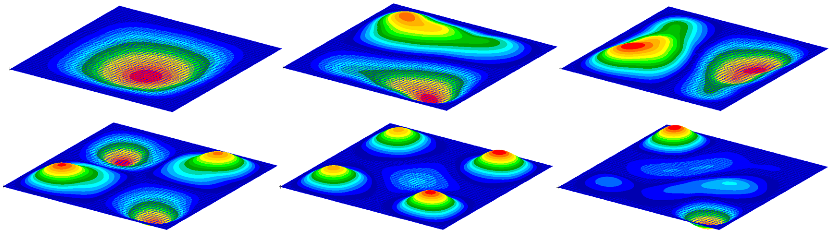
By calculating the stiffness matrix of the structure with temperature load and solving the generalized eigenvalue problem as Equation (3), frequencies and modes of the panel structure subjected to temperature field can be obtained, as shown in Table 3 and Figure 5. Natural frequencies of the panel decrease as the temperature increases, the effect of temperature becomes more significant as frequency increasement. After considering the temperature effect, the first natural frequency decreases by less than 2 , while the 6th natural frequency decreases by more than 6 . The modes of the panel are not varied obviously.
2.3. Aero-Elastic Analysis
Before aeroelastic analysis of the panel structure is performed, aerodynamic loads on the panel should be evaluated. In this paper, aerodynamic load was computed with a supersonic lifting surface method [18,19]. The equation for the supersonic lifting surface method is specified as follows:
Here, is the downwash speed at the control point of box ; is the density of air; is the flight velocity; is the pressure applied on box ; means the region where the inverted Mach cone from the th downwash point intercepts the airfoil; is the kernel function for aerodynamic calculations; and is the number of lifting surface boxes.
The pressure on the box can be written as follows:
Here is the pressure applied on the panel, and is the pressure coefficient of the lifting surface box.
Then
Let
Then
The above equation is written in the form of a matrix:
Here, is the downwash speed vector, is the matrix of aerodynamic influence coefficient, and is the vector of pressure coefficient.
The downwash velocity and vibration displacement at the grid control points satisfy the following equations:
Here, = is the reduced frequency, is the reference length, and is z-direction displacement at the control point of lifting surface box .
Thus, the pressure vector can be expressed as:
Here, is a 1 × -dimensional pressure vector.
After obtaining the pressure loads on the lifting surfaces, the pressure loads acting on the structure can be obtained by Infinite Plate Spline (IPS) [20].
Substituting the aerodynamic forces into the structural dynamics governing equations and applying a modal coordinate transformation to the equations, the governing equations for the flutter problem can be obtained as Equation (15) [21]:
Here, denotes air velocity; , and are the modal mass matrix, modal damping matrix and modal stiffness matrix, respectively; is modal aerodynamic matrix.
The modal mass matrix, modal damping matrix, modal stiffness matrix and modal aerodynamic matrix can be computed by the following Equation (16):
Here, is the matrix of the selected modal vectors; and are the spline matrices representing the relationship between the normal displacement of the grid points of the lifting surfaces, the slopes along the air flow direction and the displacements of the structural nodes, respectively; and are the chord length and the area of the panel.
Equation (15) can be solved by the P-K method [22,23]; the above equation can be rewritten as follows:
Here, is the modal displacement amplitude vector.
Equation (17) can be transformed into the following canonical form:
where
The eigenvalues can be obtained by solving the above eigenvalue problem, which leads to the computation of and . If the real part of eigenvalue is positive, the system is unstable, and if the real part of eigenvalue is negative, the system is stable.
can be calculated in the desired velocity range, then plot V–g, and the velocity at the point where is 0 is the flutter velocity.
The lifting surface mesh of the standard panel has 20 lifting surface panels in both and directions. The flutter analysis was taken by the commercial software NASTRAN 2012. The V-g and V-f plots of panel flutter with or without thermal effect are shown in Table 4 and Figure 6. The critical flutter velocity of the panel without considering thermal effect is 1050 m/s, and this value becomes 640 m/s when thermal effect is included. It can be found that the critical flutter velocity of the structure becomes lower and the aeroelastic stability of the structure becomes worse due to thermal influence.
3. Optimization via Both Thermal-Aeroelastic and Manufacture Consideration
3.1. Optimization Method
In order to improve the aeroelastic stability of the panel structure, a MMC (Moving Morphable Component) method was proposed to optimize the design of the panel structure. The MMC method was initially proposed by Guo et al. [14]. The basic idea of this method is to use the deformation and movement of components to achieve topology optimization of the structure. Areas covered with components are filled with material and areas without components are not filled with material. Compared to traditional implicit topology optimization methods such as the SIMP method, the MMC method has the advantage that the optimized structure is expressed explicitly. It can avoid the intermediate density element problem that occurs with implicit methods. The final optimization result can be explicitly expressed as a function and can be directly imported into some commercial CAD software.
The topological optimization equation based on MMC can be specified as Equation (21) [24].
Here, represents the total number of components; represents the vector of the design variables; represents the objective equation; represents the constraint equations; and is the admissible sets that belongs to.
In this paper, the components are treated as reinforcement, and the area not covered by the components is the panel (see Figure 7). We would like to use the variation in the reinforcement to adjust the frequency characteristics of the panel structure. Mostly, panel flutter occurs mostly due to the coupling of the first and the second natural modes. Therefore, in order to increase the flutter velocity of the panel, we increase the difference between the first and second natural frequencies of the panel structure.
The proposed topology optimization in Case A is to make the variable as small as possible, the number of components was set to eight, the problem formulation can be specified as Equation (22).
Here, and are the stiffness matrix and mass matrix, respectively, is the upper bound of the available materials volume.
In Case B, in order to make the optimized structural reinforcement form simple, we add the compliance as one of the constraints in this optimization example. The optimization equation can be written as Equation (23).
Here, is the compliance of the structure, and is the upper bound of compliance.
In order to make the reinforcement form closer to the standard structure and further simplify the structure, we change the number of components to four in Case C, but the objective function and constraints are not changed. The optimization column of this problem is given by Equation (24).
The sensitivity of the objective function to the design variables is derived as follows:
The derivation of the sensitivity of the eigenvalues to the design variables can be seen as follows [25].
Then
If the eigenvector is normalized with respect to , then
Left-multiplying Equation (27) by , we have
Calculations of and can be referred to as follows [24].
Here, E and are the material elasticity and density, is number of elements, is an integer, denotes topology description function, is Heaviside function, and represent the stiffness matrix and mass matrix of the element when , and fully filled with material, respectively.
The sensitivity of the volume constraint function and compliance constraint function to the design variables is given by the following equation [24].
Here, is the displacement vector of the structure.
3.2. Optimization Result of the Panel
The optimization process based on MMC method [19] is shown in Figure 8. Firstly, there is an initial design, then the structural topological description function is updated, then a finite element analysis is performed to calculate the structural dynamics eigenvalues and eigenvectors, followed by the calculation of the value and sensitivity of the constraint function and the objective function, and the design is updated. The above steps will be repeated until the convergence requirement is satisfied.
The initial design before the optimization is shown in Figure 9. The geometric parameters are the same as those of the standard structure, as shown in Table 1. The optimization results for the three constraint cases are shown in Figure 10. The optimization results can be easily imported into CAD software to generate geometric models (see Figure 11). The optimization result of Case A has the most complex form of reinforcement, which is not conducive to engineering manufacture. As the constraints are increased and strengthened, the reinforcement forms are simplified. The reinforcement form of Case C is a very simple reinforcement form and very similar to the standard structure, which can be manufactured easily.
4. Results and Discussion
In Section 3, the optimization results for the three constraint cases are obtained, here dynamics and aeroelastic characteristics of the three optimized panel structures will be simulated and discussed.
FEM modelling of the three optimization cases is proposed for the calculation of dynamics and aeroelastic characteristics (see Figure 12). The nodes and element information of the three models are shown in Table 5.
Natural frequencies of the three optimized panel structures are shown in Table 6, and the modes are shown in Figure 13, Figure 14, Figure 15, Figure 16, Figure 17 and Figure 18. For the optimized panel structure, the increase in temperature similarly causes natural frequencies of the structure to decrease while the mode remains unchanged. The frequency ratio of standard panel and optimized panels is shown in Table 7. Compared with the standard structure, the frequency ratios of the three optimized panel structures are all lower and less than 1, which means that the difference between the first and the second natural frequency of the optimized panel structure increases. The second frequency is greater than twice of the first natural frequency. It is proved that the frequency of the panel structure can be controlled by the proposed optimization design method in this paper. It also can be seen that as the constraints are increased or strengthened, the forms of panel reinforcement become simpler; however, the adjustment range of the frequency of the panel structure becomes smaller as well. So, a good balance between the optimization of aeroelasticity and manufacture is found.
The aeroelastic characteristics of the optimized panel are then evaluated. With the flutter calculation method described in Section 2, the critical flutter velocity of the optimized panel structure can be obtained, as shown in Table 8. V-g and V-f plots of the three optimized panel structures are shown in Figure 19, Figure 20 and Figure 21.
By comparing the panel structures of the four forms of reinforcement, the panel structure of Case A has the smallest frequency ratio versus the largest frequency spacing, and its critical flutter speed with or without temperature load are relatively higher. The panel structure of Case C has the simplest form of reinforcement; its critical flutter speed is slightly lower than Case A, but higher than the standard structure. This indicates that as the constraints are increased and enhanced, the frequency range of the optimized structure becomes smaller and the increasement in critical flutter speed is also limited. Overall, the aeroelastic stability of the optimized panel structure is significantly improved compared to the standard structure.
5. Conclusions
In this paper, optimization of a surrounding fixed-support panel with reinforcing ribs is studied. The MMC method is proposed after the structural dynamics and flutter characteristics of the structure with or without considering thermal effects. From different results of three optimized cases, it could be concluded that:
- Increased temperature reduces natural frequencies and critical flutter velocity of the surrounding fixed-support square panel, which means that its aeroelastic stability should be reconsidered.
- The MMC optimization method can change the dynamic characteristics of the panel in both natural frequencies and modes. However, the reinforcement forms obtained under unconstrained conditions are complicated; thus, multiple constraints should be considered in engineering applications.
- As the number of constraints increases, the frequency adjustment range of the panel structure becomes smaller. However, compared to the standard structure, the critical flutter speed of optimized panel structure can be improved by adjusting the frequency difference.
The developed MMC method proposed in this paper can be used for dynamic and aeroelasticity optimization of hypersonic structures, which are significantly influenced by aero-heating effects.
Author Contributions
Conceptualization, Y.B. and S.Z.; methodology, Y.B., S.Z. and Y.Z.; software, S.Z.; validation, Y.B. and D.Z.; writing—review and editing, Y.B. and D.Z. All authors have read and agreed to the published version of the manuscript.
Funding
This research received no external funding.
Data Availability Statement
Data are contained within the article.
Conflicts of Interest
The authors declare no conflicts of interest.
References
- Wang, X.; Yang, Z.; Chen, Z.; Gu, Y.; Wang, W.; Zhao, Y.; Wang, Y. Study on coupled modes panel flutter stability using an energy method. J. Sound Vib. 2020, 468, 115011. [Google Scholar] [CrossRef]
- Zhang, R.; Duan, J.; Pang, Y.; Yue, Y.; Xu, B. Supersonic Flutter Characteristics of a Nonlinear Spring-Supported Composite Panel Applying Curvilinear Fiber Paths. J. Vib. Eng. Technol. 2023. [Google Scholar] [CrossRef]
- Serafim, L.P.; Freydin, M.; Dowell, E.H. Flutter and Limit Cycle Oscillations of a Panel Using Unsteady Potential Flow Aerodynamics. AIAA J. 2023, 61, 5009–5017. [Google Scholar] [CrossRef]
- Lin, H.; Shao, C.; Cao, D. Nonlinear flutter and random response of composite panel embedded in shape memory alloy in thermal-aero-acoustic coupled field. Aerosp. Sci. Technol. 2022, 100, 105785. [Google Scholar] [CrossRef]
- Ouyang, X.; Liu, Y. Flutter of variable stiffness composite laminates in supersonic flow with temperature effects. J. Compos. Mater. 2021, 55, 3253–3266. [Google Scholar] [CrossRef]
- Ye, L.; Ye, Z. Aeroelastic Stability and Nonlinear Flutter Analysis of Heated Panel with Temperature-Dependent Material Properties. J. Aerosp. Eng. 2020, 33, 04020068. [Google Scholar] [CrossRef]
- Chen, X.; Nie, G. Nonlinear thermal flutter analysis of variable angle tow composite curved panels in supersonic airflow. Compos. Struct. 2021, 277, 114610. [Google Scholar] [CrossRef]
- Abdollahi, M.; Saidi, A.R.; Bahaadini, R. An investigation of aero-thermo-elastic flutter and divergence of functionally graded porous skew plates. Compos. Struct. 2022, 286, 115264. [Google Scholar] [CrossRef]
- Javadi, M.; Khalafi, V. Aerothermoelastic Analysis of Porous 2D Curved Panels. J. Vib. Eng. Technol. 2023. [Google Scholar] [CrossRef]
- Bochkarev, S.A.; Lekomtsev, S.V.; Matveenko, V.P. Finite element analysis of the panel flutter of stiffened shallow shells. Contin. Mech. Thermodyn. 2023, 35, 1275–1290. [Google Scholar] [CrossRef]
- Fazilati, J.; Khalafi, V. Aeroelastic panel flutter optimization of tow-steered variable stiffness composite laminated plates using isogeometric analysis. J. Reinf. Plast. Compos. 2019, 38, 885–895. [Google Scholar] [CrossRef]
- Stanford, B.; Beran, P.; Bhatia, M. Aeroelastic Topology Optimization of Blade-Stiffened Panels. J. Aircr. 2014, 51, 938–944. [Google Scholar] [CrossRef]
- Stanford, B.; Beran, P. Aerothermoelastic topology optimization with flutter and buckling metrics. Struct. Multidiscip. Optim. 2013, 48, 149–171. [Google Scholar] [CrossRef]
- Guo, X.; Zhang, W.; Zhong, W. Doing Topology Optimization Explicitly and Geometrically—A New Moving Morphable Components Based Framework. J. Appl. Mech. 2014, 81, 081009. [Google Scholar] [CrossRef]
- ASM Handbook Committee. Properties and selection: Nonferrous alloys and special-purpose materials. In Metals Handbook; ASM Handbook Committee: Materials Park, OH, USA, 1990. [Google Scholar] [CrossRef]
- Batoz, J.L.; Bathe, K.J.; Ho, L.W. A study of three-node triangular plate bending elements. Int. J. Numer. Methods Eng. 1980, 15, 1771–1812. [Google Scholar] [CrossRef]
- Wu, D.; Wang, Y.; Shang, L.; Wang, H.; Pu, Y. Experimental and computational investigations of thermal modal parameters for a plate-structure under 1200 °C high temperature environment. Measurement 2016, 94, 80–91. [Google Scholar] [CrossRef]
- Chen, P.C.; Liu, D.D. A harmonic gradient method for unsteady supersonic flow calculations. J. Aircr. 1985, 22, 371–379. [Google Scholar] [CrossRef]
- Liu, D.D.; James, D.K.; Chen, P.C.; Pototzky, A.S. Further studies of harmonic gradient method for supersonic aeroelastic applications. J. Aircr. 1991, 28, 598–605. [Google Scholar] [CrossRef]
- Harder, R.L.; Desmarais, R.N. Interpolation using surface splines. J. Aircr. 1972, 9, 189–191. [Google Scholar] [CrossRef]
- Qi, W.; Zhao, C.; Tian, S. Flutter Characteristics of a Joined-Wing Unmanned Aerial Vehicle with Variable Dihedral Angles. AIAA J. 2023, 61, 539–546. [Google Scholar] [CrossRef]
- Yuan, W.; Zhang, X. Numerical Stabilization for Flutter Analysis Procedure. Aerospace 2023, 10, 302. [Google Scholar] [CrossRef]
- HASSIG, H.J. An approximate true damping solution of the flutter equation by determinant iteration. J. Aircr. 1971, 8, 885–889. [Google Scholar] [CrossRef]
- Zhang, W.; Yuan, J.; Zhang, J.; Guo, X. A new topology optimization approach based on Moving Morphable Components (MMC) and the ersatz material model. Struct. Multidiscip. Optim. 2016, 53, 1243–1260. [Google Scholar] [CrossRef]
- Meng, Z.; Yang, G.; Wang, Q.; Wang, X.; Li, Q. Reliability-based topology optimization of vibrating structures with frequency constraints. Int. J. Mech. Mater. Des. 2023, 19, 467–481. [Google Scholar] [CrossRef]
Figure 1.
Standard panel structure.

Figure 2.
Temperature field distribution.

Figure 3.
FEM modelling.

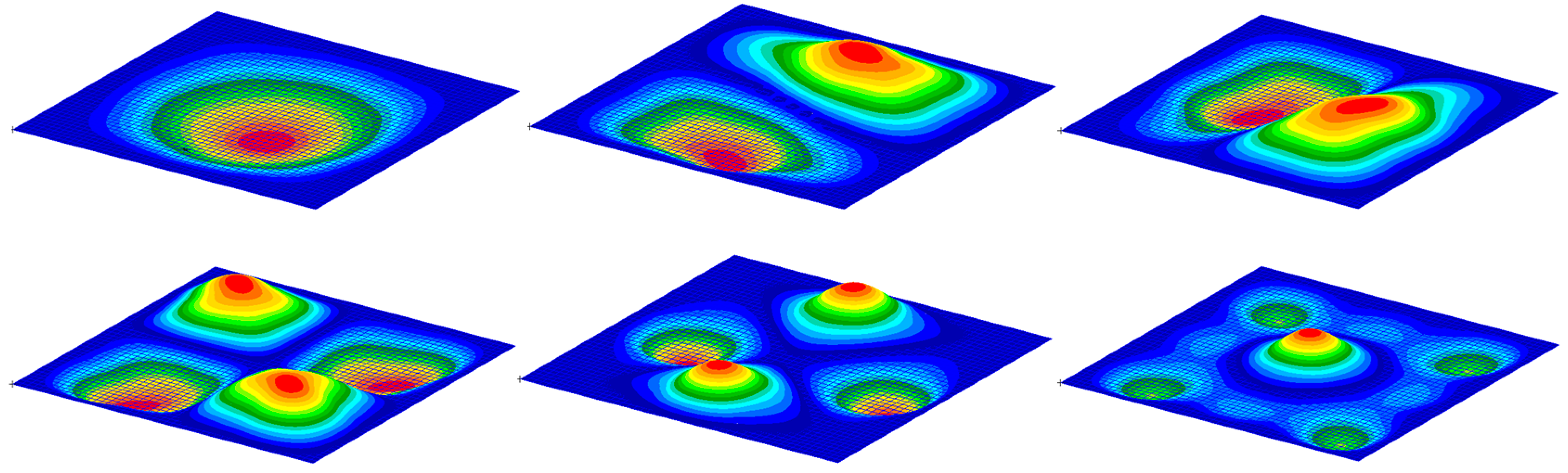
Figure 4.
Natural modes of the standard panel.

Figure 5.
Thermal modes of the standard panel.

Figure 6.
V–g and V–f plot of the standard panel: (a) without temperature effect; (b) with temperature effect.
Figure 6.
V–g and V–f plot of the standard panel: (a) without temperature effect; (b) with temperature effect.


Figure 7.
Illustration of a panel optimization process by MMC method. (The gray area is the panel and each different colored rectangles represent different components.)
Figure 7.
Illustration of a panel optimization process by MMC method. (The gray area is the panel and each different colored rectangles represent different components.)

Figure 8.
The optimization process of panel structure.

Figure 9.
Initial design of the panel.

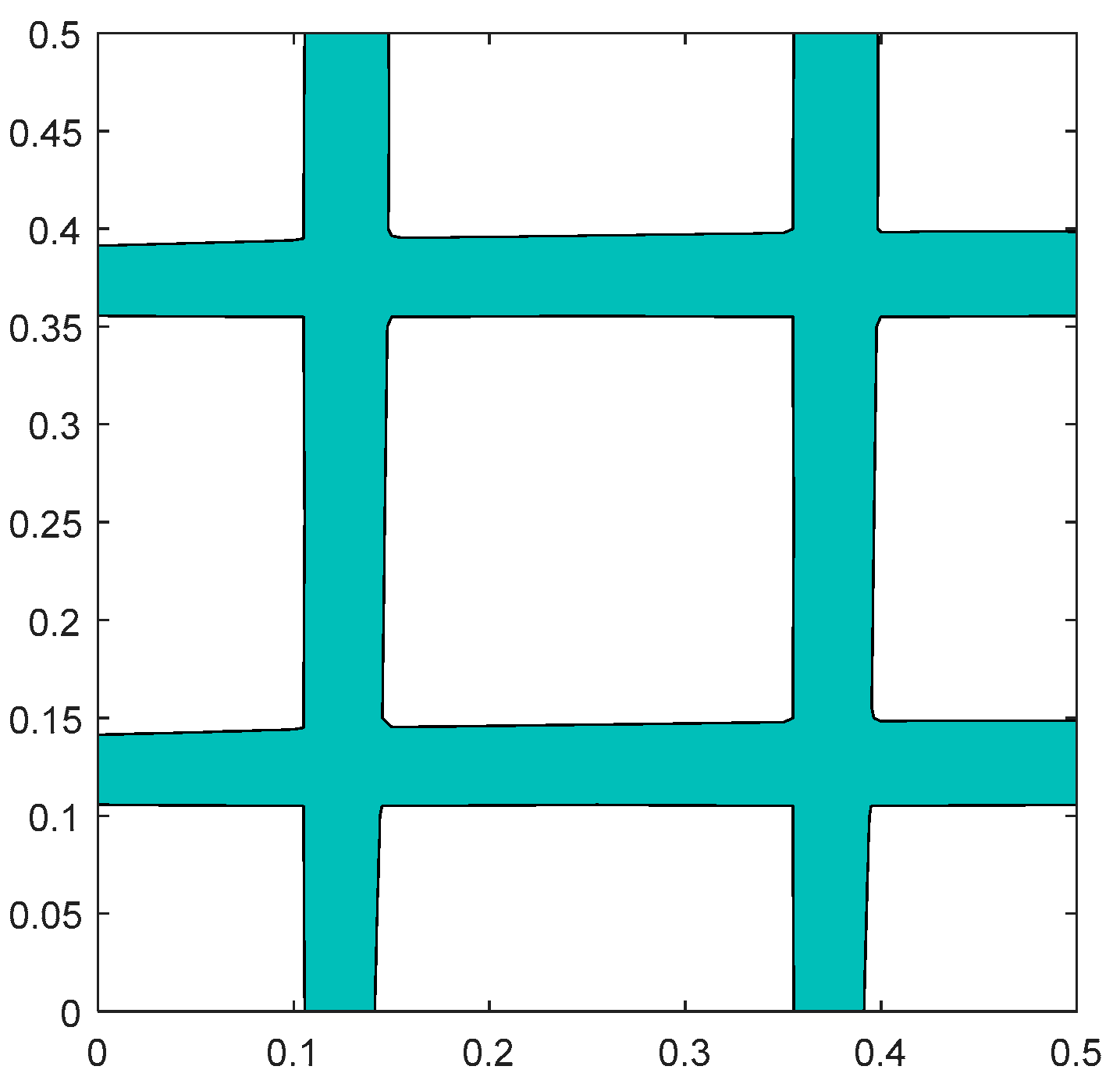
Figure 10.
Optimization results of three optimization cases.

Figure 11.
Geometry of the three optimization panels.

Figure 12.
Finite element modelling of the three optimization cases.

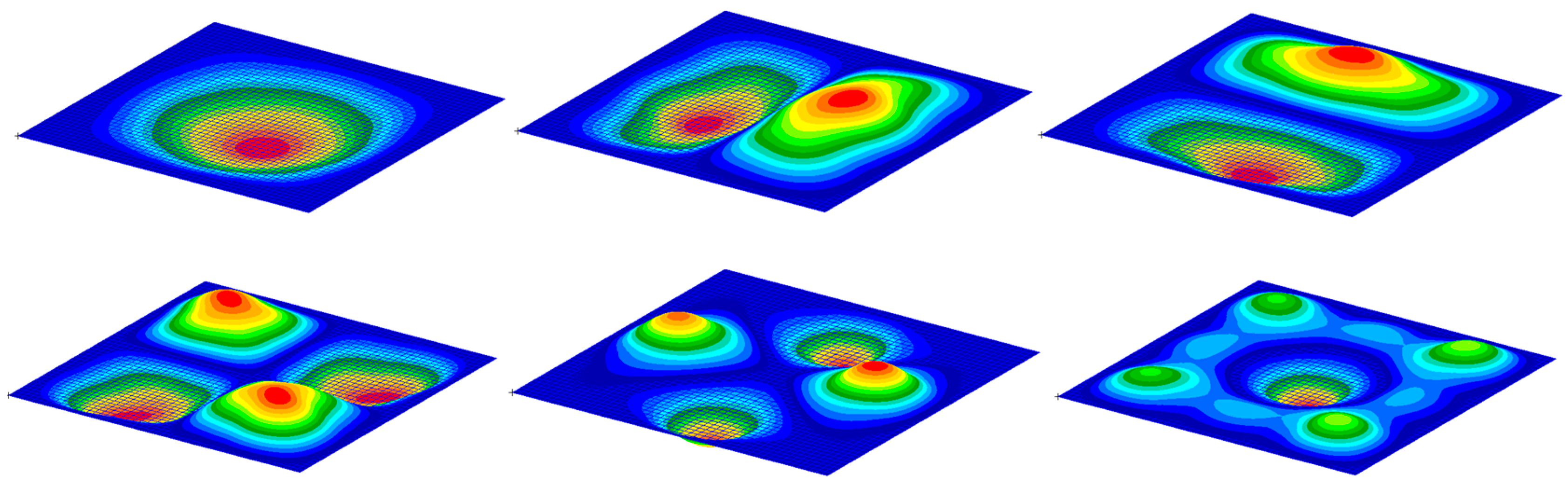
Figure 13.
Natural modes of Case A.

Figure 14.
Thermal modes of Case A.

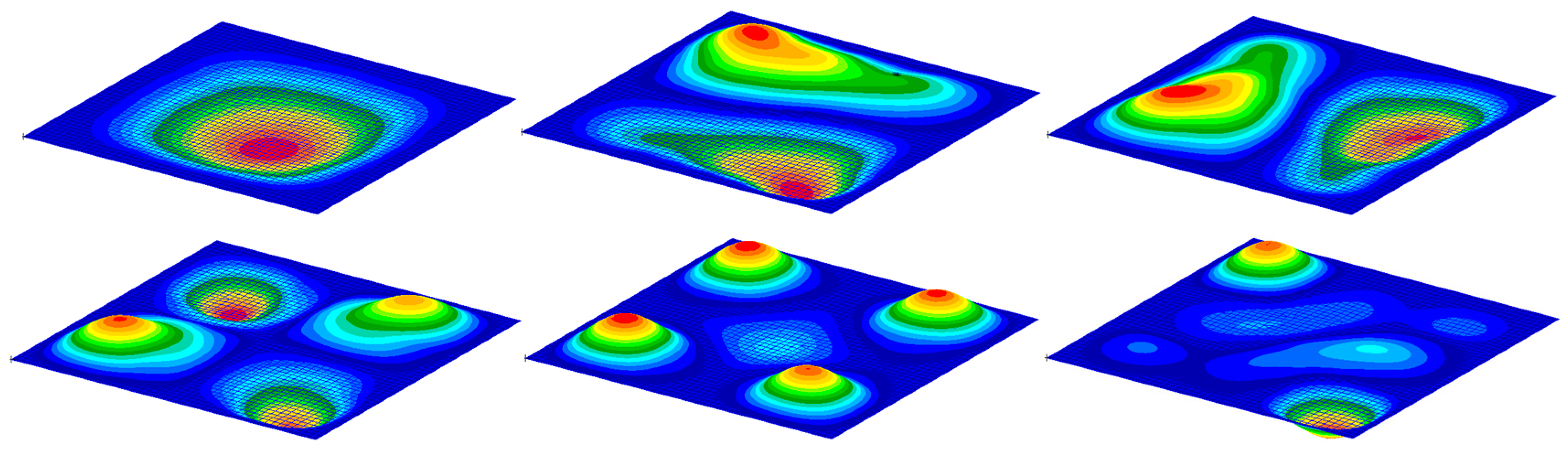
Figure 15.
Natural modes of Case B.

Figure 16.
Thermal modes of Case B.

Figure 17.
Natural modes of Case C.

Figure 18.
Thermal modes of Case C.

Figure 19.
V–g and V–f plot of Case A: (a) without temperature effect; (b) with temperature effect.

Figure 20.
V–g and V–f plot of Case B: (a) without temperature effect; (b) with temperature effect.

Figure 21.
V–g and V–f plot of Case C: (a) without temperature effect; (b) with temperature effect.


Table 1.
Panel geometry.
| Parameter | Value |
|---|---|
| Length (m) | 0.5 |
| width (m) | 0.5 |
| Thickness (m) | 0.004 (rib) |
| 0.001 (panel) |
Table 2.
Material parameters.
| Temperature (K) | Elastic (Gpa) | Density (kg/m3) | Poisson’s Ratio | Coefficient of Thermal Expansion |
|---|---|---|---|---|
| 293 | 72 | 2700 | 0.33 | |
| 373 | 71 | |||
| 423 | 68 | |||
| 478 | 63 |
Table 3.
Natural frequency of the standard panel (Hz).
| Modes | Normal Modes | Thermal Modes |
|---|---|---|
| 1 | 79.96 | 78.13 |
| 2 | 156.51 | 153.02 |
| 3 | 156.51 | 153.08 |
| 4 | 224.70 | 220.12 |
| 5 | 281.57 | 275.46 |
| 6 | 288.84 | 282.73 |
Table 4.
Critical flutter velocity of the standard panel.
| Flutter | Velocity (m/s) |
|---|---|
| Natural modes | 1050 |
| Thermal modes | 640 |
Table 5.
FEM modelling of three cases.
| Case A | Case B | Case C | |||
|---|---|---|---|---|---|
| Nodes | Elements | Nodes | Elements | Nodes | Elements |
| 7289 | 7300 | 7535 | 7524 | 7233 | 7082 |
Table 6.
Natural frequencies of three optimized panel structures ().
| Modes | Case A | Case B | Case C | |||
|---|---|---|---|---|---|---|
| Normal Modes | Thermal Modes | Normal Modes | Thermal Modes | Normal Modes | Thermal Modes | |
| 1 | 78.92 | 78.34 | 79.08 | 78.46 | 84.30 | 82.24 |
| 2 | 165.34 | 163.77 | 160.44 | 158.88 | 169.86 | 165.68 |
| 3 | 169.89 | 168.31 | 161.78 | 160.26 | 170.50 | 166.32 |
| 4 | 215.02 | 213.16 | 201.37 | 199.48 | 212.01 | 206.96 |
| 5 | 247.95 | 246.29 | 232.20 | 230.92 | 240.79 | 234.71 |
| 6 | 278.23 | 276.96 | 246.05 | 244.66 | 262.11 | 255.57 |
Table 7.
Frequency ratio of standard panel and optimized panels.
| Frequency Ratio | Standard Structure | Case A | Case B | Case C |
|---|---|---|---|---|
| 1.0445 | 0.9132 | 0.9720 | 0.9853 |
Table 8.
Critical flutter velocity of standard and optimized panels.
| Flutter Velocity (m/s) | Standard Structure | Case A | Case B | Case C |
|---|---|---|---|---|
| Normal modes | 1050 | 1200 | 1250 | 1110 |
| Thermal modes | 640 | 1140 | 1040 | 1080 |
Disclaimer/Publisher’s Note: The statements, opinions and data contained in all publications are solely those of the individual author(s) and contributor(s) and not of MDPI and/or the editor(s). MDPI and/or the editor(s) disclaim responsibility for any injury to people or property resulting from any ideas, methods, instructions or products referred to in the content. |
© 2024 by the authors. Licensee MDPI, Basel, Switzerland. This article is an open access article distributed under the terms and conditions of the Creative Commons Attribution (CC BY) license (https://creativecommons.org/licenses/by/4.0/).
Share and Cite
MDPI and ACS Style
Zhang, S.; Bai, Y.; Zhang, Y.; Zhao, D. Thermal-Aeroelastic Investigation of a Hypersonic Panel Vibration Based on a Developed MMC Method. Aerospace 2024, 11, 241. https://doi.org/10.3390/aerospace11030241
AMA Style
Zhang S, Bai Y, Zhang Y, Zhao D. Thermal-Aeroelastic Investigation of a Hypersonic Panel Vibration Based on a Developed MMC Method. Aerospace. 2024; 11(3):241. https://doi.org/10.3390/aerospace11030241
Chicago/Turabian StyleZhang, Sheng, Yuguang Bai, Youwei Zhang, and Dan Zhao. 2024. "Thermal-Aeroelastic Investigation of a Hypersonic Panel Vibration Based on a Developed MMC Method" Aerospace 11, no. 3: 241. https://doi.org/10.3390/aerospace11030241
Note that from the first issue of 2016, this journal uses article numbers instead of page numbers. See further details here.