Next Article in Journal
Optimizing Space Telescopes’ Thermal Performance through Uncertainty Analysis: Identification of Critical Parameters and Shaping Test Strategy Development
Previous Article in Journal
A Ball-Contacting Dynamic Vibration Absorber with Adjustable Stiffness and Nonlinear Characteristics
Previous Article in Special Issue
Robust Flight Tether for In-Orbit Demonstrations of Coulomb Drag Propulsion
 
 
aerospace-logo
Article Menu
Article

Electric Sail Test Cube–Lunar Nanospacecraft, ESTCube-LuNa: Solar Wind Propulsion Demonstration Mission Concept

by
Andris Slavinskis
1,2,*,
Mario F. Palos
1,
Janis Dalbins
1,2,
Pekka Janhunen
3,
Martin Tajmar
4,
Nickolay Ivchenko
5,
Agnes Rohtsalu
1,
Aldo Micciani
6,
Nicola Orsini
6,
Karl Mattias Moor
1,
Sergei Kuzmin
2,
Marcis Bleiders
7,
Marcis Donerblics
7,
Ikechukwu Ofodile
1,
Johan Kütt
2,
Tõnis Eenmäe
1,
Viljo Allik
1,
Jaan Viru
8,
Pätris Halapuu
8,
Katriin Kristmann
2,9,
Janis Sate
7,10,
Endija Briede
10,
Marius Anger
11,
Katarina Aas
2,12,
Gustavs Plonis
2,13,
Hans Teras
1,2,
Kristo Allaje
1,2,
Andris Vaivads
5,7,
Lorenzo Niccolai
6,
Marco Bassetto
6,
Giovanni Mengali
6,
Petri Toivanen
3,
Iaroslav Iakubivskyi
1,14,
Mihkel Pajusalu
1,2 and
Antti Tamm
1,2
add Show full author list remove Hide full author list
1
Tartu Observatory, University of Tartu, Observatooriumi 1, 61602 Tõravere, Estonia
2
Estonian Student Satellite Foundation, W. Ostwaldi 1, 50411 Tartu, Estonia
3
Finnish Meteorological Institute, Erik Palménin aukio 1, 00560 Helsinki, Finland
4
Institute of Aerospace Engineering, Technische Universität Dresden, Marschnerstraße 32, 01307 Dresden, Germany
5
Space and Plasma Physics, KTH Royal Institute of Technology, Teknikringen 31, 114 28 Stockholm, Sweden
6
Department of Civil and Industrial Engineering, University of Pisa, 56122 Pisa, Italy
7
Ventspils International Radio Astronomy Centre, Ventspils University of Applied Sciences, Inzenieru iela 101, 3601 Ventspils, Latvia
8
Crystalspace, Riia 181A, 51014 Tartu, Estonia
9
Department of Materials and Environmental Technology, Tallinn University of Technology, Ehitajate tee 5, 12616 Tallinn, Estonia
10
Bitlake Technologies, Inzenieru iela 101, 3601 Ventspils, Latvia
11
Department of Electronics and Nanoengineering, Aalto University, Maarintie 8, 02150 Espoo, Finland
12
Tallinn Secondary School of Science, Estonia pst 6, 10141 Tallinn, Estonia
13
Jelgava Spidola State Gymnasium, Sarmas iela 2, 3001 Jelgava, Latvia
14
Department of Earth, Atmospheric and Planetary Sciences, Massachusetts Institute of Technology, 77 Massachusetts Avenue, Cambridge, MA 02139, USA
*
Author to whom correspondence should be addressed.
Aerospace 2024, 11(3), 230; https://doi.org/10.3390/aerospace11030230
Submission received: 30 November 2023 / Revised: 23 February 2024 / Accepted: 11 March 2024 / Published: 14 March 2024
(This article belongs to the Special Issue Advances in CubeSat Sails and Tethers)

Abstract

:
The electric solar wind sail, or E-sail, is a propellantless interplanetary propulsion system concept. By deflecting solar wind particles off their original course, it can generate a propulsive effect with nothing more than an electric charge. The high-voltage charge is applied to one or multiple centrifugally deployed hair-thin tethers, around which an electrostatic sheath is created. Electron emitters are required to compensate for the electron current gathered by the tether. The electric sail can also be utilised in low Earth orbit, or LEO, when passing through the ionosphere, where it serves as a plasma brake for deorbiting—several missions have been dedicated to LEO demonstration. In this article, we propose the ESTCube-LuNa mission concept and the preliminary cubesat design to be launched into the Moon’s orbit, where the solar wind is uninterrupted, except for the lunar wake and when the Moon is in the Earth’s magnetosphere. This article introduces E-sail demonstration experiments and the preliminary payload design, along with E-sail thrust validation and environment characterisation methods, a cis-lunar cubesat platform solution and an early concept of operations. The proposed lunar nanospacecraft concept is designed without a deep space network, typically used for lunar and deep space operations. Instead, radio telescopes are being repurposed for communications and radio frequency ranging, and celestial optical navigation is developed for on-board orbit determination.

1. Introduction

1.1. Electric Solar Wind Sail and Plasma Brake in the Context of Propellantless Propulsion

The electric solar wind sail, or E-sail, was envisioned by Pekka Janhunen during the period 2004–2006 [1,2]. It has been thoroughly studied and developed since then and analysed in dozens of scientific articles in an E-sail publication repository curated by Janhunen: https://www.electric-sailing.fi/publications.html (accessed on 10 March 2024), including comprehensive reviews of the E-sail concept and its applications [3,4]. The technology consists of one or multiple thin wires, so-called tethers, which are deployed centrifugally. The tether deployment requires angular momentum and spin-up that can be provided by either a remote unit with a miniature propulsion system, or by attaching an endmass at the tip of a tether while hosting the propulsion unit on the main spacecraft body. The E-sail tether can be as thin as possible as long as it can carry the charge, but it should also have a redundant multi-wire structure for micrometeoroid resilience [5]. Deployed tethers are charged to a high positive voltage in the order of tens of k V , and electrons that are gathered by the field are removed by electron emitters located on the spacecraft. An electrostatic sheath is created around the positively charged tether, which works as an E-sail, deflecting solar wind particles and generating interplanetary spacecraft propulsion as a result.
The most effective direction to apply orbital thrust is along the orbital tangent. Chemical propulsion uses short impulses, or kicks, which change the orbital parameters nearly immediately. Electric propulsion applies low continuous thrust, which creates an orbital spiral as a result. The E-sail works in a similar way; by inclining the sail with respect to the orbital tangent and the incoming solar wind direction and by modulating the tether charge such that the thrust–vector projection onto the orbital tangent is maximal, the technology can create a small but continuous thrust, which allows for spiralling, travelling away from the Sun and even leaving the Solar System [6].
The E-sail thrust efficiency reduces following 1 / d , with d being the solar distance [7]. The reflective solar light sail and electric propulsion efficiency drops following the inverse square law of 1 / d 2 due to the reduction in solar photon flux. While the solar wind dynamic pressure also follows the inverse square law, the E-sail efficiency is partly compensated by the electrostatic sheath’s expansion in the lower plasma density further away from the Sun.
The E-sail’s spin is maintained in order to keep the tethers stretched and to modulate the charge depending on the spin sector. The E-sail’s angle with respect to the solar direction can be controlled by modulating the voltage of each tether separately to produce the net torque for attitude control and thrust vectoring [8,9]. The attitude control modes of continuous and on–off modulation have been analysed in terms of the power efficiency [10]. The research of E-sail control is actively evolving with recent results in single-tether E-sail modelling and guidance in heliocentric orbit [11].
Just as the reflective solar light sail can be used as an atmospheric drag sail for low Earth orbit (LEO) deorbiting, the E-sail can be used as an ionospheric plasma brake for LEO deorbiting [12,13]. The plasma brake always works against the orbital trajectory vector, and, therefore, creates a spiral with decreasing altitude. The plasma brake is charged negatively in the order of k V and does not require electron emitters. A common term for E-sail and plasma brake applications is Coulomb drag propulsion (CDP) [14].
The ESTCube-LuNa consortium, as described in Section 1.4, represents the majority of E-sail developers in Europe. Section 1.2 presents our heritage and recent advances in the quest to demonstrate the E-sail in orbit. There are several related and notable propellantless propulsion developments globally and which are important in the context of the Special Issue “Advances in CubeSat Sails and Tethers”, where the current article belongs. In the United States, the most prominent E-sail development has been the two-phase NASA Innovative Advanced Concepts (NIAC) “Heliopause Electrostatic Rapid Transit System”, or HERTS project, which prepared a particle-in-cell (PIC) simulation and analysed the potential E-sail missions, scenarios and spacecraft designs [15,16]. In Australia, the ionospheric plasma drag on objects in LEO has been analysed with PIC simulations and experiments [17]. A Finnish startup company named Aurora Propulsion Technologies is implementing a European Innovation Council (EIC) grant for developing the plasma brake [18], as well as a European Space Agency (ESA) project, DragLiner, to develop a Coulomb drag-based telecommunication satellite deorbiting device, in collaboration with the Finnish Meteorological Institute [19].
In terms of propellantless propulsion in general, technologies have already advanced in successful in-orbit demonstration and utilisation. The JAXA’s IKAROS spacecraft made the world’s first solar sail demonstration of photon propulsion while en route to Venus in 2010 [20]. The NanoSAIL-D2 was deployed in 2011, but orbit was too low to observe the drag effect of the small sail which the satellite carried [21]. While similar results were achieved by the LightSail 1 mission [22], the LightSail 2 mission has demonstrated solar sail control and deorbiting. The electrodynamic tether is developed by the E.T.PACK consortium who are preparing an in-orbit demonstration mission supported by the EIC [23].

1.2. E-Sail and Plasma Brake Demonstration Missions

The primary scientific and technological advancement of the ESTCube-LuNa concept, as presented by this article, is to characterise the Coulomb drag effect in solar wind environment, which would also serve as a novel demonstration of the fundamental E-sail principles in its operational environment. Several missions have attempted to demonstrate the plasma brake and E-sail components in LEO environment. ESTCube-1 [24,25] and Aalto-1 [26,27] were launched in 2013 and 2017, respectively, with the first generation of CDP experiments. However, neither the ESTCube-1 nor Aalto-1 CDP tether deployed due to engineering difficulties in accommodating a vacuum-qualified piezoelectric motor, which is sensitive to launch vibrations [28,29]. Foresail-1 [30] and ESTCube-2 were launched in 2022 and 2023, respectively, with the second generation of CDP experiments—this time, the two-phase bipolar stepper motor, phySPACE 19 (from Phytron), is space-qualified [14]. However, the Foresail-1 communication link was lost, and ESTCube-2 did not deploy from the launch vehicle. While an updated Foresail-1p is already in development, the official investigation of ESTCube-2 deployment from the rocket remains unresolved at the time of article submission. Following the Foresail-1 objectives, the Foresail-1p mission focuses on plasma brake demonstration. The ESTCube-2 mission included both the negative-mode plasma brake and the positive-mode E-sail with electron emitters, which are still of high importance to be demonstrated in LEO environment before the solar wind.
The Foresail-2 mission to reach highly elliptical orbit, such as geostationary transfer orbit (GTO), has been proposed to include a tether payload [31]. However, the Foresail-2 team reported in the Winter Satellite Workshop 2024 that the planned CDP experiment is being descoped [32]. The primary reason for taking the CDP experiment off the Foresail-2 mission is the difficulty of accommodating spinning tether requirements with other instruments and the GTO’s geometry for communications, state estimation and satellite control. The Foresail-2 descope provides us with an additional motivation to develop the ESTCube (Electric Sail Test Cube) roadmap from LEO to Moon’s orbit with LuNa (lunar nanospacecraft), as discussed in Section 1.3.
As compared with the previous E-sail demonstration mission concepts in Earth’s orbit, the case of an interaction between the lunar orbit and direct solar wind necessitates, as presented by this article, new mission analyses in terms of fundamental E-sail forces, experiment geometry and E-sail characterisation methods. Lunar orbit provides pristine solar wind conditions for about two thirds of the time: this is a major benefit over the GTO option proposed for the Foresail-2 mission. We propose a spin-stabilised mission geometry where the E-sail spin plane remains inertially fixed due to the large angular momentum a deployed tether provides. With a fixed spin plane, we will have favourable experiment conditions four times a year: when the spin plane is perpendicular or parallel to the solar wind direction. Our proposed E-sail experiments take advantage of both orientations by estimating the orbital displacement due to the thrust and the spin rate changes due to the torque.
The current paper also presents a case for an E-sail-propelled lunar escape manoeuvre. We are fully aware of the fact that the inertially fixed spin axis cannot be used for optimal trajectory control. As a “stretch goal”, the escape trajectory from lunar orbit provides us with a clear ambition for future development. By placing E-sail spin plane control thrusters on a remote unit at the tether’s tip, we would provide an optimal solution for spin plane control and, in turn, enable the trajectory manoeuvre. Most other ESTCube-LuNa technologies could be reused in a future mission concept with a remote unit.

1.3. Interplanetary and Lunar Nanospacecraft

The ESTCube-LuNa concept poses several novel challenges in the field of space technology: we envision cubesat-style solutions in communications, navigation and control for operating a lunar nanospacecraft. The proposed solutions require significant development effort; however, we suggest that alternative solutions to deep space networks (DSNs) are necessary, as the current space agency DSNs are a limited resource. By going DSN-free, a much larger community of interplanetary nanospacecraft developers would open up.
Cubesats, in fact, nanosatellites in general, are typically developed for LEO conditions, where standard solutions for communications, navigation and attitude control exist. In an effort to bring cubesats into deep space, several outstanding missions have demonstrated the applicability and challenges of the interplanetary nanospacecraft, whose mass is in the order of 10 k g . MarCO cubesats supported the InSight Mars mission by relaying data in real time [33]. The LICIACube cubesat imaged the Didymos system after the DART impact of the moon Dimorphos [34]. The Hera mission will follow up Dimorphos with two deep space cubesats—Milani (ex. APEX) and Juventas [35,36,37]. Hayabusa-2 deployed miniature rovers—Rover-1A and Rover-1B—on Ryugu and took images of the asteroid [38].
While orbiting the Moon, a lunar nanospacecraft offers a stepping stone between the LEO and interplanetary environments. As a matter of fact, NASA’s Artemis 1 Moon mission launched ten technology demonstration cubesats, some of which operated or were planned to operate independently from the main mission. However, with the increased risk associated with technology demonstration, many of the Artemis 1 cubesats did not fulfil their mission objectives, emphasising the difficulty of operating cubesats in deep space. One of the most notable of the Artemis 1 cubesats is the CAPSTONE mission, which serves as a pathfinder for cis-lunar operations and navigation for the Lunar Gateway. CAPSTONE was able to establish two-way communications with the ground [39]. Meanwhile, the ESA-supported cubesat LUMIO has been proposed to employ an inter-satellite link with a mothership in lunar orbit [40]. Either directly or via the mothership, NASA and the ESA’s lunar nanospacecrafts use DSNs, operated by agencies themselves, for communications and navigation with radio frequency (RF) ranging.
The ESTCube-LuNa concept is designed without DSNs, which is a limited resource and will not be able to serve all future deep space–especially nanospacecraft—missions. We propose repurposing radio telescopes for high-speed communications and ranging with multiple patch antennas on the nanospacecraft. For telemetry and command, we propose an omnidirectional approach in the space segment while using Yagi–Uda antennas on the ground. ESTCube-LuNa uses visual celestial navigation for determining the nanospacecraft’s position in the cis-lunar lunar system. A dedicated real-time 3D (RT3D) environment is developed for simulating the navigation world and algorithms. As opposed to RF ranging, the visual navigation solution is designed to be solved on board by employing field-programmable gate arrays (FPGAs) for image processing–detection and triangulation of the Moon, the Earth and the Sun. The visual navigation solution also provides the attitude knowledge. The attitude estimate can be improved with Sun sensors, a star tracker and an inertial measurement unit (IMU). For attitude control, we propose using miniature cubesat thrusters similar to those which have already been demonstrated in LEO [41].

1.4. ESTCube-Luna Consortium and Paper Structure

The E-sail experiments are designed by UT Tartu Observatory in collaboration with the Finnish Meteorological Institute (FMI). The high-voltage source and electron emitters as well as the miniature attitude thrusters are designed by Technische Universität Dresden (TUD). RT-16 and RT-32 radio telescopes for E-sail experiment ranging as well as for high-speed communications are operated by Ventspils University of Applied Sciences. The E-sail environment characterisation with Langmuir probes is proposed by the KTH Royal Institute of Technology. The ESTCube-LuNa stretch goal of lunar escape manoeuvre is proposed by the University of Pisa. The experience of developing ESTCube and Foresail satellite series have been used to define the ESTCube lunar nanospacecraft. The ESTCube platform is being developed by UT Tartu Observatory in collaboration with the Estonian Student Satellite Foundation. The Foresail platform is being developed by Aalto University. The tether camera and cameras for Triangulated Celestial Navigation (TCN) are designed by Crystalspace in collaboration with UT Tartu Observatory. The TCN on-board computer is designed by Bitlake Technologies.
The ESTCube-LuNa experiments are described in Section 2. The payload and experiment operations are described in Section 3. The overall results of lunar escape manoeuvre are presented in Section 4. The E-sail experiment simulations and trajectory options for ESTCube-LuNa are analysed in detail by Palos et al. [42], which serves as a modelling study, whose toolkit is being continuously updated. The ESTCube lunar nanospacecraft platform is described in Section 5. The conclusions and future work are presented in Section 6.

2. E-Sail Experiment Design for Solar Wind in Lunar Orbit

We propose the ESTCube-LuNa mission to demonstrate and characterise the electric sail in an authentic solar wind environment using a lunar nanospacecraft (i.e., limiting the spacecraft mass in the range of 10–20 kg). As presented in Section 5, our current estimate for the ESTCube-LuNa mass is 15 k g within a cubesat form factor of 2 × 4 Units (U), which is convenient for E-sail tether deployment. Figure 1 shows the ESTCube-LuNa E-sail demonstration concept in the solar wind environment around the Moon. The graphic depicts a deployed tether and the spin plane it forms as the spacecraft–tether system rotates. The 2 × 4 U side of the spacecraft is aligned with the spin plane and provides the necessary maximum moment of inertia, which increases as more tether is deployed.
The cubesat-style design approach to limit the spacecraft mass is directly linked with the E-sail performance which, in turn, is estimated based on our previous experience—the experiments proposed in this section are reusing technologies developed for Aalto, ESTCube and Foresail missions, as discussed in the Introduction. The baseline ESTCube-LuNa E-sail experiment design includes a passive endmass at the tether’s tip, which helps to generate the centrifugal force, pull out the tether and keep it stretched. An alternative remote unit solution would help in placing attitude thrusters at the end of the tether where they would be optimal for spin and spin plane control [43]. However, the endmass is preferred in the ESTCube-LuNa concept as an existing solution, while the remote unit remains on our future development roadmap to achieve trajectory control, as proposed in Section 4, where more details on the endmass–remote unit choice are provided. With the endmass solution, the spin plane control is limited; therefore, we are assuming an inertially fixed spin plane in the ESTCube-LuNa experiments.
A two-tether solution has been considered earlier in our E-sail mission designs; however, our simulations show that the stability and the control authority of the system, whose mass distribution is elongated along a single axis, does not converge (the two tethers end up drifting to the same side). Meanwhile, with a system of four or more tethers, we would be able to balance the mass distribution with respect to the centre of mass (CoM) and keep the moment of inertia low (see Section 3.2 for more details). The work of multiple-tether systems is on our development roadmap, as is the remote unit; however, the level of complexity is radically increased as compared with the development steps proposed by the ESTCube-LuNa concept.

2.1. ESTCube-Luna E-sail Experiment Requirements

As discussed in Section 3.1 below, we consider a 2 k m tether charged at 20 k V as an optimal solution between the nanospacecraft size of eight cubesat units and the E-sail experiment performance at a 1 au distance. With a Coulomb drag force of 500 n N m 1 and a charge of 20 k V [44], a 2 k m tether would yield a propulsive E-sail force of 1 m N . For a 15 k g cubesat, this force provides an estimated acceleration of 0.06   m m s 2 . The given thrust and acceleration estimates assume an idealistic case of the E-sail spin plane perpendicularly facing the solar wind stream (spin axis towards the Sun as in Figure 1). As discussed above, we have designed the ESTCube-LuNa concept assuming an inertially fixed spin plane; the setup is not optimal for trajectory control but can be conveniently used for demonstrating the E-sail fundamentals.
We propose three E-sail characterisation experiments in two different scenarios: solar wind flowing perpendicular or parallel to the spin plane. Because the spin plane will remain stable with respect to the background stars, these two situations will each happen twice per year. ESTCube-LuNa is designed to determine the attitude in three axes, as described in Section 5.5, including the solar direction measured with Sun sensors. For our experiments, we assume the solar wind direction to be anti-sunward and therefore provided by attitude sensors (i.e., ignoring local variations in the solar wind velocity vector).
In the perpendicular case, represented in Section 1, the charging of the tether during the full spin cycle would result in small changes in the orbital period, which over time, would turn into a significant drift in the true anomaly, as well as in the orbital position (as compared with the original orbit without the E-sail thrust). In this scenario, the E-sail thrust would induce a coning angle on the tether, and the coning angle versus the centrifugal force could be tested.
In the parallel case, represented in Figure 2, charging the tether while it is travelling downstream would result in a spin rate increase, as the force direction contributes to the angular momentum of the E-sail. The opposite effect happens if the E-sail is charged upstream, where the resulting force would go against the movement of the sail. The graphic depicts the spin plane parallel to the article’s page as well as parallel to the solar wind. Details of each E-sail characterisation method for the ESTCube-LuNa mission are given in the following subsections.

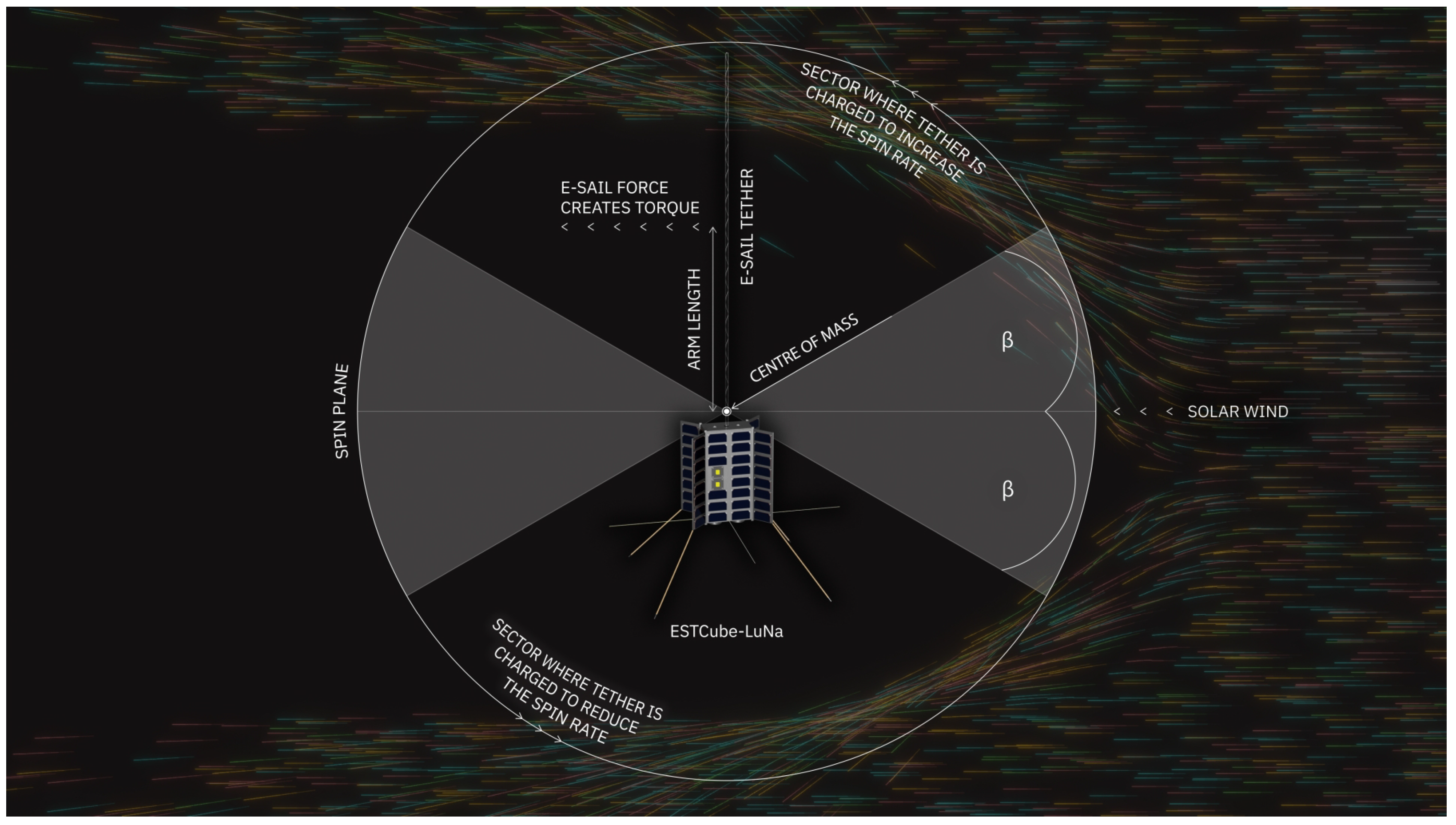
2.2. Spin Rate Modification with E-Sail Torque

The goal of the spin rate modification experiment is to measure the propulsive E-sail effect acting on the tether when it is moving either downstream or upstream of the solar wind. The optimum scenario for the experiment is represented in Figure 2, with the spin plane perpendicular to the solar wind direction. This scenario happens twice per year, with the angle changing by 1 ° per day.
The change in spin rate is
Δ ω = F r cos ( β ) t π M I
where F is the nominal E-sail force as given above; r is the arm length position on the tether where the average E-sail force acts (in the middle of the tether), as measured from the centre of mass (CoM); β is the angle between the tether and the solar direction that defines the circular sector where the tether is charged (see Figure 2); t is the time duration of the experiment; and M I is the moment of inertia of the spacecraft–tether system. Equation (1) was originally derived by Lätt et al. [24] for the LEO ionosphere, and here, we have adapted it for the solar wind case.
As discussed in Section 3.2, the ESTCube-LuNa CoM is 3.35   m outside the spacecraft when the full 2 k m tether is deployed. In a general case, the charged tether on the spacecraft side of the CoM would contribute negatively to spin rate modification. For ESTCube-LuNa, the CoM shift is insignificant in terms of the spin rate because it is inside the Debye length and inside the sheath. However, this would change if a remote unit (750 g [43]) was used instead of a passive endmass, introducing a significant shift in CoM when compared with the ESTCube-LuNa endmass of 2.5 g.
Considering an estimated E-sail force of 1 m N , an arm length of 1000 m, a β angle of 20 ° and a moment of inertia of 70,380 kg m2, Equation (1) yields a change in angular velocity of 2.44   ×   10 4 deg/ s . This equates to approximately 1 deg/ s if the experiment is run for 4200 s, something that can easily be detected by the on-board attitude systems of cubesats or the proposed visual navigation system in Section 5.5.2.

2.3. Orbit Modification with E-Sail Thrust

As shown in Figure 1, the spin plane is perpendicular to the solar direction in the orbit modification experiment, which maximises the E-sail thrust. We propose performing the experiment in three-day windows around these ideal scenarios, which occur twice per year. The estimated E-sail thrust in the ideal point is 1 m N and it scales down as the perpendicular geometry between the spin plane and the solar wind direction changes (not yet considered in our analyses).
We estimate the resulting orbital displacement with a General Mission Analysis Tool (GMAT) simulation of an idealistic electric thruster, which has an incredibly high specific impulse of 100,000 s, and it does not decrement the spacecraft mass. The power consumption is not considered in GMAT (only the thrust), since it is modelled differently in an operational E-sail. We assume that such an electric thruster in GMAT emulates the thrust created by the E-sail. The use of GMAT provides us with high-fidelity orbital and celestial models, including a high-order lunar gravity field and eclipses.
The GMAT thruster points in the solar direction and provides the thrust away from the Sun, as the E-sail does (see Figure 3 on the left). For preliminary analysis, we select an arbitrary lunar orbit of 763 k m in altitude and a 15 ° inclination. For maximal orbital displacement, we execute a finite burn of 1 m N thrust when the ESTCube-LuNa spacecraft is moving towards the Sun, which, in turn, reduces the orbital altitude. The thrust is not provided while the spacecraft is in an eclipse. We simulate two spacecrafts—“E-sail” and “NoSailClone”—to compare how the thrust changes the initial orbit, which is the same for both spacecraft. By executing the thrust experiment for three days, the orbital period is changed by some 100 s between the “E-sail” and “NoSailClone” spacecrafts, as shown in Figure 3 on the right. The reduction in orbital altitude (the difference between semi-major axes) is in the rage of 14 k m between the “E-sail” and “NoSailClone” spacecrafts at the end of the experiment. The change in the E-sail spacecraft’s orbital period introduces a significant drift in the true anomaly and the orbital position when compared with the simulated spacecraft without the thrust.
To characterise the orbital displacement, we propose a ranging experiment for precise orbit determination (see Section 5.4 for more details), which can be complemented with the Triangulated Celestial Navigation (TCN) optical solution, as described in Section 5.5.2, when ESTCube-LuNa will not be able to establish a link with the ranging ground station. In this case, precise orbit determination needs to be performed before and after the E-sail thrust experiment. A high-accuracy orbit propagator model and an orbit determination measurement uncertainty model are necessary for extrapolating the pre-experiment orbit and comparing it with the post-experiment orbit as a result of the E-sail thrust, both measured by radio frequency (RF) ranging.

2.4. E-Sail Tether Deflection

Upon its deployment, the E-sail tether lags behind the normal of the spacecraft side panel, and after deployment, it will oscillate around the side-panel normal. As discussed in Section 3.2, the maximum lagging angle is a design parameter for tether deployment. The oscillations with respect to the nominal tether deployment direction (side-panel normal) must be limited to ± 45 ° to provide a safe limit in order to avoid the tether wrapping around the spacecraft. Upon charging the tether and in addition to the post-deployment oscillations, the tether will enter a coning motion of 2 ° under the 1 m N thrust, assuming reasonable 3 c N tether tension. The amplitude of coning motion is an estimation based on the previous simulation experience and on the given design parameters. By coning motion, we mean that the tether describes a slightly conical path as the solar wind force keeps it deflected from the spin plane into the anti-sunward direction. In the actual mission, the tether’s motion will be much more complex and a subject of characterisation. We propose a ± 45 ° field-of-view (FoV) camera for monitoring the endmass and characterising the tether motion due to the deployment oscillations and the thrust coning. As the design baseline, we use the Crystalspace “Suupistri” monitoring camera [45].
In order to monitor the tether deployment and motion with the camera, it is essential that at least one of the sail components is bright enough to be captured. There are three options to achieve this: making the endmass reflective, treating the surface of the tether itself so that it becomes reflective, or adding a bright light-emitting diode (LED) at the endmass. The second option would require finding a material and a coating process that turns the tether reflective without altering its electrical properties. The LED “beacon” method would require the development of a standalone power circuit inside the endmass with its own solar panel, adding complexity to the setup. The option of making the endmass reflective and using sunlight for detection is preferred because of its simplicity.

3. ESTCube-Luna E-Sail Payload and Experiment Operations

The E-sail employs the solar wind for propulsion by deflecting plasma particles off their original course thanks to the Coulomb drag interaction. For the ESTCube-LuNa concept, we are designing the simplest viable E-sail with a single tether and a simple endmass pulling it out. Each E-sail tether consists of a multi-thread structure made of thin wires (50 μ m or thinner), necessary for micrometeoroid tolerance. The tether is stored on a reel, which is controlled by a motor. The tether is deployed using the centrifugal force, which requires high-rate spin manoeuvring and closed-loop control between tether deployment and angular momentum provision. The tether is charged with a 20 k V or more high-voltage supply, and by electron emitters continuously pumping out negative charge from the spacecraft.
E-sail prototypes and demonstration missions have been developed since 2008 by the ESTCube, Aalto and FORESAIL teams in Estonia and Finland. The ESTCube-1, Aalto-1, ESTCube-2 and Foresail-1(p) missions have been developed for the LEO environment, which differs from lunar orbit in two crucial aspects: the E-sail is tested in its ionospheric plasma brake mode for deorbiting in LEO and the magnetic field cannot be used for attitude determination and control in lunar orbit. The Foresail-2 team has addressed some of these challenges by designing the plasma brake operations and experiments for highly elliptical orbit around the Earth. In addition, Foresail-2 houses a high-grade magnetometer from the Space Research Institute (IWF) of the Austrian Academy of Sciences, which requires a strict magnetic cleanliness approach. Therefore, a typical combination of reaction wheels and a thruster-based attitude control system cannot be used, as the reaction wheels spin at a frequency too close to the ultra-low frequency (ULF) waves that the mission is designed to observe. On Foresail-2, a purely thruster-based solution is designed to orient the spacecraft towards the Sun and spin it up. The Foresail-2 cubesat is designed to spin around the Y-axis. Thrusters facing in X− and X+ directions can provide the required control authority for the spin manoeuvres. For further attitude control, at least two thrusters facing in Y− and Y+ directions, respectively, are needed. To provide redundancy, two thrusters will be used in each direction by the Foresail-2 satellite. For the ESTCube lunar nanospacecraft concept, we propose preliminary E-sail payload and experiment operations, which are based on the previous designs of ESTCube-2 (see Figure 4), Foresail-1(p) and Foresail-2 [14,24,27,28,29,30,31,46].

3.1. E-Sail Hardware

The E-sail tether, after deployment from the spacecraft, forms an unusual space structure: the designed length of the hair-thin tether is 2 k m in the case of the ESTCube-LuNa concept. While the whole tether mass is merely 45 g with a 2.5   g endmass, the moment of inertia of the spin plane can extend 7   ×   10 4   k g m 2 (see Section 3.2 for more details of why the moment of inertial is so large). In order to provide spin plane stability during the initial metres of tether deployment (avoid the shift between major axis of inertia), we have designed the ESTCube-LuNa structure such that the maximum moment of inertia already lies in the spin plane before tether deployment starts. This is achieved by selecting an elongated non-standard cubesat structure of 2 × 4 units, where the tether deployment direction is aligned with the 4-unit side (see Figure 5).
The ESTCube-2 Coulomb drag propulsion experiment, depicted in Figure 4, is designed to perform plasma brake (negative polarity) and E-sail (positive polarity with electron emitters) experiments in the LEO ionosphere. The ESTCube-2 payload design includes all components necessary for the ESTCube-LuNa E-sail experiment; the tether is stored on a reel, which is controlled by a motor (includes a clutch, encoder ring and dedicated control board) and, when deployed, the tether will be charged with a high-voltage source and electron emitters. In the ESTCube-LuNa concept, we are increasing two main performance parameters of the E-sail payload—the tether length and the voltage—to the level necessary for meaningful propulsion experiments in the solar wind environment (see the experiment design in the previous section).
As discussed in Section 5, the preliminary ESTCube-LuNa design allocates a whole cubesat unit for the the tether reel. The reel must be placed at the side that the tether is deployed: 1 × 2-unit face of ESTCube-LuNa. If the reel were to be bigger, then the spacecraft dimensions would increase in order to host the tether camera and attitude thrusters on the same side as the E-sail reel. Based on the development experiences of ESTCube-2 and Foresail-1(p), we estimate that the 1-unit cubesat reel is able to host a tether of 2 k m in length. An automated tether factory is in development by the FMI in collaboration with Aurora Propulsion Technologies and is critically necessary for large-scale tether production extending into the kilometre range. The actual tether length storage capacity on the reel will be determined with the automated tether factory. Meanwhile, we can assume the following: if less tether fits on a 1-unit reel, then the tether charge voltage can be increased, requiring less physical space for higher performance. The dynamical behaviour of the E-sail tether in LEO, as was planned for the Foresail-1 cubesat mission, has been analysed by Sakamoto et al. [47]. Safety criteria for flying the E-sail tether through a solar eclipse should be analysed and designed for as it can undergo significant thermal contraction and expansion [48].
The baseline voltage for charging the ESTCube-LuNa E-sail is 20 k V . As an example of performance vs. size, the Spellman UM8-40 high-voltage module series provides several options in the 8 k V to 40 k V range [49]. The baseline voltage of 20 k V can be provided by a 204 g module with dimensions of 119 m m × 38 m m × 25 m m . If we were to increase the voltage to 40 k V , then the mass of the high-voltage module would increase to 371 g (dimensions: 177 m m × 41 m m × 29 m m ). Upon starting ESTCube-LuNa development, other options for high-voltage source will be considered. The high-voltage electronics will implement both voltage and current control, either to fix the energy of the electron beam or enable stable emission currents for long-term operation.
In terms of the E-sail power management, the high-voltage level depends on the surrounding plasma and the available power to achieve the thrust performance independent of the solar wind density. By employing Equation (2) with the 20 k V tether charge and the 2 k m tether length, the electron current gathered by the tether is 42 μ A , which results in the power consumption of 0.84   W . As discussed in Section 5, 2 W is budgeted for the E-sail, which accounts for the efficiency of the high-voltage source and for variations in the solar wind density. If the solar wind is denser than normal and no more power is available than budgeted, then the high-voltage source will smoothly reduce the voltage to be less than the nominal 20 k V . In the case of ESTCube-LuNa’s demonstration, providing a specific E-sail thrust value will not be possible, but we can run the system with maximum available power and maximum allowed voltage.
The electron emitter will be based on carbon nanotube (CNT) technology, which has already been successfully tested in orbit on the 1-unit cubesat UWE-4 [41]. The ESTCube-LuNa electron emitter will feature a different geometry and spacing to accommodate the much higher operating voltage. Special care will be necessary to limit the energy of sparks at these high voltages in order to not damage both the emitter and the electronic circuit. The electron beam divergence half-angle is estimated to be 35 ° .

3.2. E-Sail Deployment

A 2 k m tether is selected as the baseline for the E-sail thrust experiment analysis. The tether length is based on an estimated total unreeling time, which should not exceed one year (design decision). The angular momentum required to extend the tether is provided by highly miniaturised and fuel-efficient field emission electric propulsion (NanoFEEP) thrusters developed at TUD (also responsible for high-voltage source and electron emitters). These have already been demonstrated in orbit and provide 8 μ N of thrust each. The preliminary deployment system analysis uses two NanoFEEP thrusters for nanospacecraft spin-up. A longer tether could be deployed by providing more thrust to produce the required angular momentum (more and/or upgraded thrusters) or by extending the allowable deployment time beyond one year.
Numerical simulations were used to estimate the spacecraft and tether behaviour during deployment. The simulation considers the spacecraft–tether system in an ideal case without external disturbances. The tether was simulated as a chain of high-stiffness springs with a changing length and the changes in mass distribution due to the tether reel-out were considered. The following is a list of assumptions used in the analysis. The nanospacecraft has a uniformly distributed mass of 15 k g and a moment of inertia of 0.25   k g m 2 . The tether has a mass per unit length of 2.27   ×   10 5   k g m 1 , which results in a total mass of 45.4   g for the whole tether. An endmass of 2.5   g is attached to the end of the tether.
The expected E-sail force per unit length of tether is 500 n N m 1 , which gives 1 m N for a 2 k m tether. The centrifugal force ( F c f ) expected to keep the tether stable should be at least five times the E-sail force, based on the previous simulation experience. Therefore, the tension along the deployed tether should be at least 5 m N . The centrifugal force of a point mass is given by F c f = m R ω 2 . Considering the 3.35   m centre-of-mass shift due to tether extension, the required rotation period to achieve the given tension is 629 s . The moment of inertia of a thin rigid rod rotating around one of its ends is given by M I = 1 3 m r 2 . Accounting for the centre of mass shift, the inertia of the longer part of the tether is 60,230 kg m2. Adding the effects of the endmass, the satellite and the remaining tether, the total moment of inertia comes out as 70,380 kg m2. Combining this with the required angular velocity produces an angular momentum of 703 N m s . Table 1 lists the estimated deployment parameters for various tether lengths at 5 m N tension.
For ESTCube-LuNa’s planned tether length of 2 k m , the final angular momentum is 702 N m s . With an undeployed tether, this requires an extremely high spin rate, which the communication and electrical power systems cannot handle. Therefore, the deployment must be executed in steps, as shown in the following figures. Figure 6 depicts the deployment of the first 60 m of tether and shows a potential safety issue; during the initial deployment, up to approximately 6 m , the tether tension increases from 5 m N to 85 m N instead of decreasing. This is because the relative increase in the endmass distance is very high, while the relative increase in the system inertia—and hence the reduction in angular velocity—is low. For an actual mission, the initial spin-up and deployment strategy must be analysed in more detail to avoid over-stressing the tether. Figure 7 shows the deployment of the full 2 k m . The exact sizes of the steps depend on the minimum and maximum tether tensions allowed during deployment. The maximum is limited by tether strength, and the minimum by the tether deflection angle from the side normal. The most critical parameters to control during the deployment to avoid damaging or tangling the tether are spin and torque axis alignment accuracy and tether deflection angle from the side normal.
Figure 8 shows the dynamic tether behaviour during the beginning stages of deployment. When the tether is being unreeled, it lags behind the spacecraft rotation and starts oscillating. When reeling is stopped, the oscillation continues, but the lagging effect disappears. The oscillations die out slowly over time. The oscillation frequency depends on the length of the tether, similarly to a pendulum. The amplitude of the oscillations and the lagging effect can be limited by increasing the tether tension (i.e., the angular velocity of the spacecraft). The initial increasing of tether tension, mentioned above, is clearly visible in the top right plot.
With the NanoFEEP thrusters, whose performance is used as the baseline for the simulation study above, special care must be taken to ensure that the metal plume would not hit the solar cells and the tether. As discussed in detail in Section 5, the deployable solar panels are placed at a 45 ° angle from the thruster direction in a so-called X-configuration. The panels are kept safe by limiting the nominal plume half-angle to <±25 ° . For the tether, the safety is achieved by pointing the thrusters orthogonally with respect to the tether deployment direction and by limiting the tether deflection angle to ± 45 ° , leaving a 20 ° safety margin between the thruster plume and the tether.

3.3. E-Sail Environment Characterisation

The order of magnitude estimation of the current collected by the tether can be based on the orbital-motion-limited approach (see, e.g., [2,50]). For the intended tether (assuming simplified, as compared with Figure 4, a 4-fold Hoytether made of 50 μ m diameter wires), the current per unit length is
d I d z = 4.3 d w e n 0 2 e V 0 m e
where e is the elementary charge, n 0 is the solar wind density, V 0 is the tether voltage, m e is the electron mass and d w is the wire diameter. The estimated constant of 4.3 comes from the 4-fold Hoytether, corrected for the fact that the length of the two X-shaped crossing middle wires (see Figure 4) is somewhat longer than the length of the parallel wires. For a wire of diameter 50 μ m , a typical solar wind density of about 7 cm 3 and 10 k V tether voltage (conservative estimate, as compared with the planned 20 k V ), the current is about 15 μ A k m 1 .
The current collected by the tether should be balanced by the electron emitter, so that the latter is capable of providing currents in the range of tens of μ A .
The interaction of the spacecraft with the solar wind plasma can be rather complex for the E-sail system, given the presence of the tether, which is biased to high positive voltage, and an electron emitter. The reflection of solar wind ions by the charged tether sheath creates a region of counter-streaming ions, which may develop plasma instabilities. The sheath around the tether and the spacecraft depends on the interplay of all these parameters and affects the performance of the E-sail.
A Langmuir probe instrument can be used to characterise the spacecraft–plasma interaction. A pair of probes can be implemented, with cylindrical current-collecting electrodes at the tips of rigid cylindrical booms extending from the edges of the solar panels, to bring the probes away from the spacecraft body. Each probe can be biased independently. Analysis of the current–voltage characteristics of the probes provides the parameters of the plasma environment and the spacecraft potential with respect to it. As the typical Debye length is larger than the boom dimensions, the Langmuir probes will in most cases be inside the E-sail’s sheath, which can be characterised for different modes of the E-sail operations.

4. ESTCube-Luna Stretch Goal: Lunar Escape Manoeuvre

This section discusses the possibility of expanding the scope of the ESTCube-LuNa mission by performing a lunar escape manoeuvre using the E-sail tether as the sole source of thrust. The successful completion of such a manoeuvre achieved by an ESTCube-LuNa-based architecture would confirm the potential of E-sail as source of thrust outside the Earth’s magnetosphere, thus allowing other innovative mission scenarios to be planned. The analysis is based on the outcomes of the lunar escape scenario discussed in Palos et al. [42], and assumes a representative tether length and voltage values of 2 k m and 20 k V , respectively (with a characteristic acceleration of a c =   0.06   m m s 2 ), in agreement with the rest of the experiment analysis described in this paper. To perform a lunar escape manoeuvre, the spacecraft must be able to effectively control the orientation of its spin plane. Accordingly, in the remainder of the analysis, it is assumed that the spacecraft is constantly capable of adjusting the E-sail spin plane during the escape trajectory, and the required attitude control effort is estimated.
The ESTCube-LuNa design is not optimal for spin plane control because the attitude thrusters are placed on the main spacecraft and the tether endmass consists of a few grams of aluminium to provide the necessary cable tension due to centrifugal force. The positioning of the thrusters can be optimised for control purposes by introducing a remote unit, which would house the attitude thrusters for spin rate and spin plane control. A remote unit could also effectively exploit the maximum arm length for thruster-controlled rotation and centrifugal tether deployment. However, to keep the design of the ESTCube-LuNa (i.e., the endmass solution) simple and to facilitate the spin rate modification experiment, the variant with remote unit is not considered for the baseline design. Nevertheless, it is worth noting that a similar architecture has been proposed by Iakubivskyi et al. [43] and could be combined with the ESTCube-LuNa concept as a possible next step after the demonstration of the E-sail concept. The same E-sail also provides spin plane control capabilities; however, this aspect has yet to be designed and demonstrated by the ESTCube-LuNa or a similar mission. Based on the previous discussion, the spin plane modification of the E-sail represents a significant technological challenge for the design of the E-sail control system and remote unit (if any). Accordingly, a preliminary estimate of the attitude control effort required by a lunar escape manoeuvre is performed to assess the feasibility of the objective. In particular, the average daily attitude changes required by the escape manoeuvre are obtained.
The lunar escape manoeuvre is analysed by modelling the spacecraft as a point mass in a selenocentric orbit, subject to the gravitational force of the Moon, the E-sail thrust, the gravitational attraction of the Earth (third body) and the perturbative force due to the Moon’s oblateness. The spacecraft is assumed to be governed by a locally optimal control law, discussed at length in the work of Palos et al. [42], which can be summarised as follows. The time derivative of the pericentre radius and eccentricity can be maximised by appropriately orienting the propulsive acceleration vector along the two unit vectors k ^ p and k ^ e , respectively. Consequently, if the pericentre radius r p of the osculating orbit is less than a given threshold value r p min , the E-sail spin axis k ^ B is oriented so as to maximise the projection of acceleration along k ^ p to avoid impact with the lunar surface; otherwise, the unit vector k ^ B is oriented so as to maximise the projection of propulsive acceleration along k ^ e to reach the escape conditions as quickly as possible. Finally, the E-sail voltage source is turned off when the spacecraft is in eclipse conditions, when the Moon crosses the Earth’s magnetosphere, and when the projection of the propulsive acceleration along k ^ p is negative. More details about the E-sail steering law and the definitions of unit vectors k ^ p and k ^ e are given in the work of Palos et al. [42].
The E-sail attitude is conveniently described by considering an inertial reference frame T I ( S ; x I , y I , z I ) with unit vectors { i ^ I , j ^ I , k ^ I } , whose axes are parallel to those of the International Celestial Reference Frame (ICRF). The E-sail orientation is then defined by the two control angles, ζ [ 0 , π ) rad and ψ [ 0 , 2 π ) rad, where ζ is the angle between the direction of the E-sail spin axis k ^ B and that of k ^ I , and ψ is measured counterclockwise from i ^ I to the projection of k ^ B on the plane ( i ^ I , j ^ I ) (see Figure 9).
The two key orbital parameters of the starting orbit that exert the most significant influence on the escape time are the semimajor axis and the inclination. Specifically, when the semimajor axis increases, a reduction in the escape time is observed due to an increase in the specific mechanical energy of the parking orbit around the Moon. As for the inclination, the escape time reaches its minimum when the initial value is on the order of 1.53 ° . This particular inclination angle corresponds to the case where the orbital plane is parallel to the ecliptic plane. Consequently, when the inclination is close to 1.53 ° , the thrust component lying on the orbital plane becomes more substantial, so that a significant component of the propulsive acceleration can be effectively used for the escape manoeuvre. For this reason, an initial inclination of 1.53 ° was chosen in the simulations presented, assuming that the E-sail starts its manoeuvre in the most favourable condition, in order to reduce the escape time.
As an example, three parking orbits with different values of the semimajor axis are considered. All these orbits share a common inclination of 1.53 ° and an eccentricity of 0.6 . The high eccentricity of the parking orbit ensures that the initial pericentre is close to the Moon surface while the semimajor axis is long enough to allow escape conditions to be reached within a year and a half. Table 2 presents an overview of the results for these three scenarios. For each case, the escape time, average daily changes in the E-sail control angles, and the percentage of time the sail is active are given.
The results summarised in Table 2 highlight that a lunar escape manoeuvre is achievable in a relatively short time with an E-sail tether. However, attitude variations pose a major challenge for a spacecraft propelled by an E-sail since, as expected, the attitude control effort is significantly larger than that required by a heliocentric transfer with flight times on the order of years. This is mainly due to the fact that the Sun–spacecraft direction varies with a characteristic timescale comparable to the period of the osculating orbit, so frequent changes of the rotation plane must be made to apply the selected control law in selenocentric scenarios. This consideration also explains why orbits with larger semimajor axes require less significant changes in the rotation plane over time, as observed in Table 2. However, the attitude angle variations reported in Table 2 are relevant for all of the three scenarios and imply large changes of the E-sail rotation plane. Taking into account that the spacecraft moments of inertia would be high due to the presence of the spinning tether, such attitude changes pose a significant technological challenge for the design of the E-sail control system and the remote unit. Nevertheless, it is worth remarking that this analysis makes use of a control law aimed at minimising the escape time, given the limited thrust available. Further research can be conducted to refine the control law to reduce variations of the E-sail spin plane.

5. ESTCube-Luna Preliminary Mission Requirements and Platform Design Solutions

5.1. System Engineering

As detailed in the previous sections, the ESTCube-LuNa mission is required to perform novel E-sail propulsion experiments in lunar orbit. The E-sail experiments are designed to provide force measurements and estimates in thrust and torque modes. Although Section 4 provides results for a potential lunar escape manoeuvre, the baseline ESTCube-LuNa mission is designed with a fixed E-sail spin plane, which in turn is not well suited for complex trajectory manoeuvres. The ESTCube-LuNa E-sail experiment sets the following top-level mission requirements for the platform and operations:
  • Launch and operate in lunar orbit.
  • Operate DSN-free by developing alternative solutions for communications and navigation without the access to space agency DSNs.
  • Withstand three years of operations in the lunar orbit environment: solar and cosmic particles, radiation and large temperature fluctuations between sunlit and shadowed sides.
  • Perform and monitor the spin manoeuvres and E-sail tether deployment using reaction wheels, attitude thrusters and sensors as well as the tether camera.
  • Operate and characterise the E-sail performance by charging the tether and measuring changes in orbit, spin rate, tether deflection angle and surrounding plasma environment.
  • Ensure sufficient power production during E-sail tether deployment and operations.
  • Estimate the ESTCube-LuNa position using optical navigation and triangulation of the Moon, the Earth and the Sun.
  • Estimate the ESTCube-LuNa attitude by combining the navigation solution with Sun sensors, inertial measurement unit (IMU) and star tracker (the tether camera can double as a star tracker when the spin rate is low, such as after tether deployment).
  • Transmit telemetry and commands via a wide-beam antenna.
  • Transmit data and perform ranging with narrow-beam antennas.
The ESTCube-LuNa spacecraft hosts the E-sail payload, the tether camera (TC), ranging experiment (RE) and Langmuir probes (LPs). As detailed in the following subsections and shown in Figure 10, the ESTCube-LuNa platform consists of the communication system (COM), electrical power system (EPS), on-board computer (OBC) as well as the attitude and navigation system (ANS). Based on the ESTCube-2 architecture, the Avionics stack includes the COM, EPS and OBC, while the new ANS is introduced to connect and control six cameras and eight thrusters.
Communications is one of the primary challenges when bringing cubesats from LEO to cis-lunar and deep space. Typically, deep space networks (DSNs) of space agencies are used for communications, even for cubesats, as in the case of NASA’s Artemis 1. For ESTCube-LuNa, we are designing communications and navigation from scratch, without assuming access to DSNs, and in this paper, we present the preliminary solutions and considerations. The COM includes a high-speed communication (HSCOM) system, designed for data downlink and radio ranging, with X-band patch antennas on the spacecraft and repurposed radio telescopes in Ventspils International Radio Astronomy Center (VIRAC) in Irbene, Latvia. The VIRAC antennas will be limited in availability; therefore, we cannot assume this functionality for everyday operations. The low-speed communication (LSCOM) solution has an ultra-high frequency (UHF) turnstile antenna on the spacecraft and Yagi–Uda antennas at the ground station in Tõravere, Estonia. The named ground stations are available within the current ESTCube-LuNa consortium. In case of insufficient data transfer, we shall look for ground segment partnerships on the other side of the Earth. The preliminary concept of operations is shown in Figure 11.
Since DSNs are also used for navigation, we propose an alternative optical navigation solution as part of the ANS. Triangulated Celestial Navigation (TCN) or the “tuna-can navigation system” is equipped with five 120 ° field-of-view (FoV) cameras for maximal coverage of the entire sky. Four cameras are placed in two tuna cans on the opposite side from the E-sail payload. The fifth navigation camera is placed on the E-sail side along with the tether camera, which can double as a star tracker. The ANS includes a powerful on-board computer for image processing with FPGAs. The ESTCube-LuNa spacecraft operates in spin-stabilised mode provided by attitude thrusters (ATs) and reaction wheels (RWs).
The EPS includes four deployable panels in the X-configuration for balanced power production during yearly seasons and assuming the fixedness of the E-sail spin plane. Two diagonal deployable panels would be enough to provide the same power, but in such a case, the deployed panels would tend to be aligned with the spin plane, which complicates attitude dynamics. The four-panel X-configuration keeps the 2 × 4 U side aligned with the spin plane. Batteries and other heavier components are placed near the E-sail payload for increased arm length from the tether attachment point to the ATs.
The current spacecraft design fits in 2 × 4 cubesat units (8 U) with an estimated mass of less than 15 k g , which was assumed in the experiment simulations in Section 2. The preliminary mass budget is given in Table 3.

5.2. Electrical Power System (EPS)

The current design of ESTCube-LuNa EPS includes 106 solar cells, placed on the four largest sides of the spacecraft, as well as on four deployable panels in X-configuration (diagonally from each of the 4U long corners). Estimated maximum power production from the solar panels on the larger nanospacecraft sides is up to 28 W and 20 W .
The two smallest sides of the cubesat are occupied by the E-sail payload and navigation cameras without solar panels. Since ESTCube-LuNa is designed to operate with an internally fixed spin plane, there will be two seasons when, during two parts of a spacecraft spin, the sides uncovered by solar panels will point towards the Sun. While this is unfavourable, we only need to run the E-sail experiment for one-third of the time in the spin modification experiment, as detailed in Section 2.2.
The main power consumers of ESTCube-LuNa are given in Table 4. In further ESTCube-LuNa mission analyses, special care must be taken in analysing the energy consumption while running the different power modes, for example, data transmission and ranging sessions, attitude and navigation manoeuvres, and payload operations.

5.3. On-Board Computer (OBC)

The ESTCube-LuNa OBC is designed to command platform subsystems and payloads during nominal operations. The OBC receives and distributes mission control commands via COM and collects and sends housekeeping, telemetry and experiment data. Since the ESTCube-LuNa mission is limited in the link between the spinning nanospacecraft and ground stations, the OBC must be able to operate the platform and payloads autonomously. The on-board storage must accommodate weeks of experiment data and employ lossless compression to reduce the downlink data budget. The EPS serves as a backup captain during safe modes, when all manoeuvres and experiments are paused until a connection with the ground is established. The OBC’s real-time clock (RTC) synchronisation also relies on the EPS’s battery-backed RTC.
The plan is to interface the payloads via two cubesat space protocol (CSP) buses. An ARM architecture-based rad-hard microcontroller will deliver the high performance required to handle tasks and communication between all subsystems and payloads.

5.4. Communication (COM)

The distance and relative motion between the Moon and the Earth, as well as the E-sail spin motion, require the ESTCube-LuNa concept to include a combination of communication solutions, while also assuming that there can be extended periods without a direct line of sight between the lunar nanospacecraft and Earth-based ground stations. The operations must work with communication delays of more than 1 s and minutes-long periods of communication blackouts caused by the E-sail rotation and occultation by the Moon. For telemetry and command, we propose a turnstile antenna on the ultra-high frequency (UHF) band. This would cover a the whole sky and could be used for regular spacecraft monitoring, telemetry and control from the ground. For data downlink and ranging, we propose a set of patch antennas on the X-band placed on the four largest sides of the cubesat (the same sides as the body-mounted solar panels). On the 1 × 4 U sides, there are transmit-only antennas for improved data downlink budget over the spacecraft’s rotation. On the 2 × 4 U sides, there is a pair of transmit (Tx) and receive (Rx) antennas for performing the ranging experiment. This can also be used for emergency firmware upload. The COM system comprises two subsystems: low-speed communication (LSCOM) and high-speed communication (HSCOM).

5.4.1. Low-Speed communication (LSCOM)

UT Tartu Observatory operates a UHF-band Yagi–Uda antenna in Tõravere, Estonia, which is continuously accessible and can be used for low-speed telemetry and command Tx and Rx of ESTCube-LuNa. The gain of the LSCOM ground station antenna is about 23 dBi in the 435 M Hz frequency band. In case of insufficient data transfer, we plan to find more antennas across the globe.
For LSCOM on board ESTCube-LuNa, we are assuming an isotropic antenna system: a turnstile antenna which does not have any blind spots, like other types of antennas do. A turnstile antenna is a near-isotropic-type antenna that consists of two crossed dipoles, oriented at right angles to each other (see Figure 12 on the right). For example, ISISPACE has a 1 U deployable antenna system that can be fitted on the 1 × 2 U side, opposite to the E-sail payload.

5.4.2. High-Speed Communication (HSCOM)

The Ventspils International Radio Astronomy Centre (VIRAC) in Irbene, Latvia, includes two radio telescopes—RT-32 and RT-16—that have parabolic dishes of 32 m and 16 m in diameter, respectively (see Figure 13). The telescopes are being repurposed to allow for satellite uplink and downlink communications. We assume RT-16 as the baseline antenna for data downlink. RT-32 can be employed for the ranging experiment (RE), as well as for emergency needs when RT-16 is not available. The repurposed radio telescopes for communications and ranging is the primary means of ESTCube-LuNa to operate independently of space agency DSNs.
ESTCube-LuNa is designed to use the X-band 8400 M Hz frequency band for high-speed downlink. VIRAC 16 m ground station can provide a maximum gain of 58.9 dBi with a total cryogenic receiver gain of 90 dB. Equipped with multiple directional antennas on different cubesat sides, the HSCOM includes antenna switches to establish a line-of-sight communication with the Earth. To minimise the nanospacecraft surface area taken by the patch antennas (for better power production), our preliminary design includes Endurosat X-band patch antennas, just one quarter of a cubesat unit in surface area (see Figure 12). We place two pairs of patch antennas on two sides of the nanospacecraft for two-way communications and ranging. Depending on the spin plane of the E-sail, directional communication sessions will be available only during the times of the month when Earth will cross the beam of the directional antenna.
For ranging experiments, it is necessary to develop new capabilities, especially in terms of the space segment. The Iris deep space transponder by NASA JPL in the US [51,52] includes deep space communications and ranging functions, but it is not available for Europe-based projects like ESTCube-LuNa.
As discussed in Section 2.3, the ESTCube-LuNa ranging experiment is required to determine accumulated orbital changes in the range of a hundred of seconds in the orbital period. Our initial analyses suggest that for a simplified experiment, the narrow-band ranging signal can be injected into the communications’ downlink signal. The most critical requirement originating from the ranging experiment is the need for a coherent frequency conversion chain in the communication hardware. The RF experiment also requires a full-duplex radio capable of receiving and transmitting at the same time, such that we can lock the transmitter carrier to the received carrier with a constant ratio. Special care must be taken in implementing duplex filters and isolators for reliable operations.

5.5. Attitude and Navigation System (ANS)

The ESTCube-LuNa attitude and navigation system (ANS) concept is designed for cubesat operations in Moon orbit without DSN support. We propose a five-camera optical navigation solution to solve the triangulation problem between the Moon, the Earth and the Sun. The concept includes eight attitude thrusters (ATs) for spin-stabilised attitude operations and spin-up for tether deployment (see Figure 5). Short-term attitude corrections and compensation for disturbances can be performed by a set of reaction wheels (RWs), which can be desaturated using the ATs. Before tether deployment, ESTCube-LuNa is designed to perform pointing, which is achieved by turning the spin plane. When the tether is deployed, the tilting with respect to the tether requires continuous effort from RWs and ATs. Such complex attitude manoeuvres in realistic orbital conditions have not been analysed yet.
Based on ESTCube-2 heritage, we can reuse Sun sensors (SSs) as well as the star tracker (ST), and possibly combine the ST with the tether camera. The triangulated celestial navigation (TCN) solution also provides an attitude estimate. The ESTCube-LuNa ANS system should include on-board orbit and attitude propagators in order to fill in the measurement gaps and missing axis (i.e., SSs provide a two-axis solution). The optical navigation solution serves as a low-accuracy backup for the RF ranging experiment. A Kalman filter (KF) or similar capabilities should be provided for fusing TNC, ST and SS measurements with orbital and rotational models.
The regular mission design tools, such as STK and GMAT, do not include photorealistic 3D capabilities, which in turn are necessary to model and develop optical navigation and attitude estimation, available in blender-based environments, such as SISPO [53], FlyByGen [54] and AIS [55]. Furthermore, open-loop control, which takes advantage of optical measurements, requires real-time 3D modelling. It is only recently that they are becoming photorealistic, with the Unreal Engine 5 (UE5) leading the way [56]. The UniversaL Physics-based Solar System Exploration Rover Simulator (ULYSSES) tool provides photorealistic real-time lunar rover mission simulations [57]. Inspired by ULYSSES, we propose an orbital model tool, real-time 3D (RT3D), which currently includes 3D models of the Moon, the Earth and the Sun, which are the necessary celestial bodies for ESTCube-LuNa mission design and navigation algorithm development.

5.5.1. Attitude Thrusters (ATs)

The ESTCube-LuNa spacecraft is designed to have eight attitude thrusters (ATs) for spin rate and spin plane orientation control, as shown in Figure 5. For regular operations before tether deployment, the attitude thrusters can be used together with RWs for maintaining the spin rate and pointing the spin plane. For spin-up and tether deployment manoeuvres, ATs are used directly to provide the angular momentum between periods of tether deployment, as discussed in Section 3.2.
While a specific AT technology is not selected yet, in the mission design, we have assumed that each thruster produces 8 μ N , which has been demonstrated in orbit on board a one-unit cubesat UWE-4 [41] using the highly miniaturised field-emission electric propulsion (NanoFEEP) thrusters from TUD [58], also an ESTCube-LuNa consortium member. When two ATs burn at the maximum thrust, as required by the spin-up for tether deployment, they consume up to 2.5   W .
The NanoFEEP thrusters are extremely compact, with the specific impulse reaching 4000 s . The extreme efficiency provides the necessary spin-up propulsion budget with just 12.1   g of propellant, spread between two thrusters. The NanoFEEP thruster ionises liquid metal and the ions are accelerated by a strong electric field. The resulting metal plume’s half-angle is in the ± 35 ° nominal range and can reach ± 50 ° at high thrust, as in our case. We assume that a focusing electrode is necessary to limit the nominal plume half-angle to <±25 ° . As shown in Figure 5, the X-configuration deployable panels form a 45 ° angle with the thrust direction. The maximum plume half-angle should be several degrees smaller than ± 45 ° in order to avoid coating of solar cells by a safe margin.

5.5.2. Triangulated Celestial Navigation (TCN)

In order to navigate in deep space, most nanospacecrafts use radiometric tracking through NASA’s and other space agencies’ deep space networks. For the ESTCube-LuNa mission, this is not feasible, as it is too expensive and inaccessible. To solve this problem, ESTCube-LuNa will use triangulated celestial navigation (TCN, also “Tuna Can Navigation”) to determine the nanospacecraft’s position relative to the Sun, the Moon and the Earth. In order to achieve this, the spacecraft will have five Crystalspace CAM1U cameras (originally developed for ESTCube-1 [59]) with 120 ° FoV, covering almost all directions, leaving just minor blind spots. CAM1U cameras were chosen, as they are small, low-power and achieve all necessary requirements for navigation purposes. The cameras have field-programmable gate arrays (FPGAs), such as microchip polarfire, so the processing of navigaiton images can occur in situ. To maximise the overall FoV from all cameras, four of the five cameras are placed in two custom tuna can modules at one end of the spacecraft (opposite from the E-sail side). The final camera is on the other side of the spacecraft and can also be used for tracking the early deployment of the E-sail tether (the tether camera is specifically designed to track the endmass throughout the deployment).
The main principle behind optical navigation in space is obtaining intersecting vector measurements towards known bodies and using resection (triangulation) to determine the location of the spacecraft based on those measurements [60]. Measurements of a minimum of three different bodies are required to determine the spacecraft location in 3D. Additionally, the spacecraft attitude can be determined from these measurements, as the orientations of the navigation cameras relative to the spacecraft reference frame are known.
For ESTCube-LuNa, the main navigational task is to determine the nanospacecraft’s position when orbiting the Moon. For this purpose, the bodies considered for imaging are the Earth, the Moon and the Sun. Distant stars have no direct use for optical navigation, as their relative location does not change within the bounds of lunar orbits. The precise locations of these three bodies are publicly available and frequently updated.
For the best result, the bodies used for the measurements should be as spread out as possible while not forming a single plane with the spacecraft. There are two worst case situations in which the spacecraft will not be able to determine its position: (1) the three bodies are aligned in a straight line and (2) any one body is hidden from view by another one.
There are two main sources of errors: the absolute positional uncertainty of the measured bodies and the optical measurement error. The latter consists of camera placement on the spacecraft, optical construction of the cameras and image processing. As the spacecraft will be orbiting the Moon, it is likely that the Moon will not fit the image frame. Therefore, special attention must be paid to the accurate estimation of the location of the centre of the Moon based on the curvature of its observed limb.
The exact algorithms for obtaining a navigation and attitude solution are not available yet. A rough “brute force” estimate indicates that a measurement error of 1 ° in any of the three vectors gives an average of 50 k m error in the spacecraft position. In the worst case, this error may go up to 125 k m . The TCN solution can be used for rough orbit determination and as a backup for the ranging experiment (e.g., filling in gaps between RF ranging sessions).

5.5.3. Real-Time 3D (RT3D)

The TCN system, as described in the previous subsection, requires on-board optical navigation algorithms. We have developed a proof of concept for the real-time 3D (RT3D) modelling environment in the 3D game engine Unreal Engine 5 (UE5), as shown in Figure 14. The motivation to use UE5 for ESTCube-LuNa is the engine’s novel ability to render near-photorealistic images in real time. The TCN solution will be used for attitude manoeuvres; hence, the modelling environment should respond in real time. In later phases, the ESTCube-LuNa mission can be simulated with the RT3D feed working with TCN cameras in a loop, either via a digital interface or by filming screens (multiple screens are necessary to cover the whole sky). In a way, ESTCube-LuNa ANS will play RT3D as a video game, with TCN providing the visual input.
The current RT3D concept includes 3D models of the Sun, the Moon and the Earth. The celestial object textures are extracted from the Solar System Scope [61]. The celestial bodies can follow pre-programmed orbits, which should be replaced with a position input from an orbit propagator. For example, DOCKS includes an open-source propagator [62]. The rotation of celestial bodies can also be extracted from DOCKS. We would need to develop spacecraft attitude dynamics ourselves while taking advantage of the DOCKS’s trajectories to model attitude and orbit disturbances.

6. Conclusions and Future Work

This paper follows the Electric Sail Mission Expeditor (ESME) [42] as the second in a series on E-sail demonstration in the solar wind. We have proposed a 2 k m tether charged at 20 k V to achieve the propulsive E-sail force of 1 m N by placing a 15 k g 2 × 4 U cubesat in lunar orbit. The E-sail force can be estimated by generating the thrust and the torque in two experimental modes. When the E-sail spin plane is perpendicular to the solar wind and charged either when moving towards or away from the Sun, within three days, we can create the change in orbital period of 100 s, which should be estimated with the ranging experiment. We can also observe the E-sail tether coning motion with the tether camera. The tether motion can be used to estimate the E-sail force and to characterise E-sail behaviour. When the E-sail spin plane is parallel to the solar wind and charged either when rotating towards or away from the Sun, we can achieve the change in angular velocity of more than 1 deg/ s . Langmuir probes are proposed to characterise the E-sail plasma environment. This paper proposes novel navigation and communication solutions without access to space agencies’ deep space networks. Future work includes a detailed analysis of all aspects of the ESTCube-LuNa. A summary of our proposed method is as follows:
  • Integrate the ESME thrust and spacecraft attitude dynamics with DOCKS in order to simulate generic E-sail experiments and missions with a high-fidelity numerical orbit propagator.
  • Integrate the ESME tether dynamics with high-fidelity attitude control for tether deployment.
  • Refine the escape manoeuvre and develop other trajectory options by integrating realistic spin plane change abilities: either with E-sail or with thrusters on a remote unit.
  • Develop ESTCube-LuNa trajectory options with a fixed spin plane.
  • Refine the design of experiments, payloads and estimate the E-sail tether length with real-life experiments: how much tether can be hosted on a reel with an automated tether factory?
  • Develop deep space communication and ranging nanospacecraft solutions for which there are no European transponders.
  • Develop navigation and attitude determination systems and algorithms.
  • Develop attitude control systems and algorithms.
  • Continue developing the real-time 3D modelling environment.
  • Develop a remote unit technology concept for a potential ESTCube lunar escape mission concept with optimal thruster placement for E-sail spin plane control. We see this as the primary showstopper for implementing the lunar escape manoeuvre, as proposed in Section 4 with modelling details described in the work of Palos et al. [42].
In terms of launching ESTCube-LuNa, the European Union’s IOD/IOV programme, as well as the European Space Agency’s “Small Missions for Exploration–Destination the Moon”, suggests Ariane 6. While the ESA call is not suitable for the ESTCube-LuNa concept, the IOD/IOV programme has already supported the ESTCube-2 LEO launch and can potentially support the ESTCube-LuNa launch, given funding opportunities from elsewhere. The specific orbit depends on a specific rideshare opportunity, with which the potential ESTCube-LuNa mission would need to be aligned.

Author Contributions

Conceptualization, A.S., M.F.P., J.D., P.J., M.T., N.I., G.P., M.B. (Marcis Bleiders), M.D., J.K., J.V., P.H., J.S., E.B., M.A., H.T., K.A. (Kristo Allaje), A.V., L.N., M.B. (Marco Bassetto), G.M., P.T., I.I. and M.P.; Methodology, A.S., M.F.P., P.J., N.I., A.R., K.A. (Katarina Aas), A.M., N.O., K.M.M., S.K., G.P., M.B. (Marcis Bleiders), M.D., I.O., J.K., T.E., V.A., J.V., P.H., K.K., J.S., E.B., M.A., H.T., K.A. (Kristo Allaje), A.V., L.N., M.B. (Marco Bassetto), G.M., P.T., I.I. and M.P.; Software, A.S., M.F.P., A.R., K.A. (Katarina Aas), A.M., N.O., K.M.M., G.P., J.K., L.N., M.B. (Marco Bassetto) and G.M.; Validation, A.S., M.F.P., K.A. (Katarina Aas), A.M., N.O., K.M.M., G.P., J.K., M.A., H.T., L.N., M.B. (Marco Bassetto) and G.M.; Formal analysis, A.R., K.A. (Katarina Aas), A.M., N.O., K.M.M., S.K., G.P., I.O., J.K., L.N., M.B. (Marco Bassetto), G.M. and I.I.; Investigation, A.S., M.F.P., P.J., M.T., N.I., A.R., K.A. (Katarina Aas), A.M., N.O., K.M.M., S.K., G.P., J.K., M.A., H.T., K.A. (Kristo Allaje), A.V., L.N., M.B. (Marco Bassetto), G.M., P.T. and I.I.; Resources, A.S., M.B. (Marcis Bleiders), M.D., T.E., V.A., J.V., P.H., J.S., E.B., H.T., K.A. (Kristo Allaje), A.V., P.T. and M.P.; Data curation, A.S., A.R., A.M. and J.K.; Writing—original draft, A.S., M.F.P., A.R., K.A. (Katarina Aas), A.M., N.O., K.M.M., G.P., I.O., J.K., V.A., L.N. and M.B. (Marco Bassetto); Writing—review & editing, A.S., M.F.P., J.D., P.J., M.T., N.I., M.B. (Marcis Bleiders), J.K., A.V. and G.M.; Visualization, A.S., M.F.P., K.A. (Katarina Aas), A.M., N.O., K.M.M., G.P. and J.K.; Supervision, A.S., M.F.P., P.J., N.I., T.E., V.A., K.K., H.T., K.A. (Kristo Allaje), A.V., L.N., G.M., P.T., I.I., M.P. and A.T.; Project administration, A.S., K.K., A.V. and A.T.; Funding acquisition, P.J., M.P. and A.T. All authors have read and agreed to the published version of this manuscript.

Funding

The research was conducted using the Estonian Research Council core facilities’ grant TT8.

Data Availability Statement

Data are contained within the article. The ESME software package is available as an open source at https://github.com/marioferpa/ESME (accessed on 10 March 2024), under MIT license, and are being updated to include simulations performed in GMAT by this research article. The GMAT simulation is available upon request. The RT3D software package is being prepared for open-source publication.

Conflicts of Interest

The authors declare no conflict of interest.

References

  1. Janhunen, P. Electric Sail for Spacecraft Propulsion. J. Propuls. Power 2004, 20, 763–764. [Google Scholar] [CrossRef]
  2. Janhunen, P.; Sandroos, A. Simulation study of solar wind push on a charged wire: Basis of solar wind electric sail propulsion. Ann. Geophys. 2007, 25, 755–767. [Google Scholar] [CrossRef]
  3. Bassetto, M.; Niccolai, L.; Quarta, A.A.; Mengali, G. A comprehensive review of Electric Solar Wind Sail concept and its applications. Prog. Aerosp. Sci. 2022, 128, 100768. [Google Scholar] [CrossRef]
  4. Janhunen, P.; Toivanen, P.; Envall, J.; Merikallio, S.; Montesanti, G.; Gonzalez Del Amo, J.; Kvell, U.; Noorma, M.; Lätt, S. Overview of electric solar wind sail applications. Proc. Est. Acad. Sci. 2014, 63, 267–278. [Google Scholar] [CrossRef]
  5. Seppänen, H.; Rauhala, T.; Kiprich, S.; Ukkonen, J.; Simonsson, M.; Kurppa, R.; Janhunen, P.; Hæggström, E. One kilometer (1 km) electric solar wind sail tether produced automatically. Rev. Sci. Instrum. 2013, 84, 095102. [Google Scholar] [CrossRef] [PubMed]
  6. Wiegmann, B.M. NASA Innovative Advanced Concepts (NIAC): Heliopause Electrostatic Rapid Transit System (HERTS), Final Report; NASA: Washington, DC, USA, 2015. [Google Scholar]
  7. Janhunen, P.; Toivanen, P.K.; Polkko, J.; Merikallio, S.; Salminen, P.; Haeggström, E.; Seppänen, H.; Kurppa, R.; Ukkonen, J.; Kiprich, S.; et al. Invited Article: Electric solar wind sail: Toward test missions. Rev. Sci. Instrum. 2010, 81, 111301. [Google Scholar] [CrossRef] [PubMed]
  8. Toivanen, P.K.; Janhunen, P. Spin Plane Control and Thrust Vectoring of Electric Solar Wind Sail. J. Propuls. Power 2013, 29, 178–185. [Google Scholar] [CrossRef]
  9. Toivanen, P.; Janhunen, P. Thrust vectoring of an electric solar wind sail with a realistic sail shape. Acta Astronaut. 2017, 131, 145–151. [Google Scholar] [CrossRef]
  10. Toivanen, P.; Janhunen, P.; Envall, J. Electric sail control mode for amplified transverse thrust. Acta Astronaut. 2015, 106, 111–119. [Google Scholar] [CrossRef]
  11. Bassetto, M.; Quarta, A.A.; Mengali, G. Thrust model and guidance scheme for single-tether E-sail with constant attitude. Aerosp. Sci. Technol. 2023, 142, 108618. [Google Scholar] [CrossRef]
  12. Janhunen, P. Electrostatic Plasma Brake for Deorbiting a Satellite. J. Propuls. Power 2010, 26, 370–372. [Google Scholar] [CrossRef]
  13. Janhunen, P. Simulation study of the plasma-brake effect. Ann. Geophys. 2014, 32, 1207–1216. [Google Scholar] [CrossRef]
  14. Iakubivskyi, I.; Janhunen, P.; Praks, J.; Allik, V.; Bussov, K.; Clayhills, B.; Dalbins, J.; Eenmäe, T.; Ehrpais, H.; Envall, J.; et al. Coulomb drag propulsion experiments of ESTCube-2 and FORESAIL-1. Acta Astronaut. 2020, 177, 771–783. [Google Scholar] [CrossRef]
  15. Wiegmann, B.M.; Stone, N.; Wright, K. The Heliopause Electrostatic Rapid Transit System (HERTS)-Design, Trades, and Analyses Performed in a Two Year NASA Investigation of Electric Sail Propulsion Systems. In Proceedings of the 53rd AIAA/SAE/ASEE Joint Propulsion Conference, Atlanta, GA, USA, 10–12 July 2017; American Institute of Aeronautics and Astronautics: Reston, VA, USA, 2017. [Google Scholar] [CrossRef]
  16. Johnson, L.; Polzin, K. Electric Sail Propulsion for Deep Space Missions. In Proceedings of the 70th International Astronautical Congress (IAC), Washington, DC, USA, 21–25 October 2019. [Google Scholar]
  17. Lafleur, T. Charged aerodynamics: Ionospheric plasma drag on objects in low-Earth orbit. Acta Astronaut. 2023, 212, 370–386. [Google Scholar] [CrossRef]
  18. Aurora Propulsion Technologies Receives EIC Grant and Equity Funding-AURORA—Propulsion Technologies. Available online: https://aurorapt.fi/news/aurora-propulsion-technologies-receives-eic-grant-and-equity-funding/ (accessed on 28 November 2023).
  19. Peitso, P.; Janhunen, P.; Genzer, M.; Yli-Opas, P.; Laurila, H.; Hieta, M.; Haukka, H.; Macieira, D.; Toivanen, P.; Polkko, J.; et al. ESA Dragliner-Coulomb drag based telecommunication satellite deorbiting device. In Proceedings of the Winter Satellite Workshop, Espoo, Finland, 17–19 January 2024; Aalto University: Espoo, Finland, 2024. [Google Scholar]
  20. Mori, O.; Shirasawa, Y.; Mimasu, Y.; Tsuda, Y.; Sawada, H.; Saiki, T.; Yamamoto, T.; Yonekura, K.; Hoshino, H.; Kawaguchi, J.; et al. Overview of IKAROS Mission. In Advances in Solar Sailing; Springer: Berlin/Heidelberg, Germany, 2014; pp. 25–43. [Google Scholar] [CrossRef]
  21. Vulpetti, G.; Johnson, L.; Matloff, G.L. The NanoSAIL-D2 NASA Mission. In Solar Sails; Springer: Berlin/Heidelberg, Germany, 2015; pp. 173–178. [Google Scholar] [CrossRef]
  22. Betts, B.; Nye, B.; Vaughn, J.; Greeson, E.; Chute, R.; Spencer, D.A.; Ridenoure, R.W.; Munakata, R.; Wong, S.D.; Diaz, A.; et al. LightSail 1 mission results and public outreach strategies. In Proceedings of the 4th International Symposium on Solar Sailing, Japan Space Forum, Tokyo, Japan, 17–20 January 2017. [Google Scholar]
  23. Sanchez-Arriaga, G.; del Pino, A.; Sharifi, G.; Tarabini Castellani, L.; García-Gonzaléz, S.; Ortega, A.; Cruces, D.; Velasco, A.; Orte, S.; Ruiz, A.; et al. The E.T.PACK-F Project: Towards a flight-ready deorbit device based on electrodynamic tether technology. In Proceedings of the AIAA SCITECH 2024 Forum, Orlando, FL, USA, 8–12 January 2024. [Google Scholar] [CrossRef]
  24. Lätt, S.; Slavinskis, A.; Ilbis, E.; Kvell, U.; Voormansik, K.; Kulu, E.; Pajusalu, M.; Kuuste, H.; Sünter, I.; Eenmäe, T.; et al. ESTCube-1 nanosatellite for electric solar wind sail in-orbit technology demonstration. Proc. Est. Acad. Sci. 2014, 63, 200–209. [Google Scholar] [CrossRef]
  25. Envall, J.; Janhunen, P.; Toivanen, P.; Pajusalu, M.; Ilbis, E.; Kalde, J.; Averin, M.; Kuuste, H.; Laizans, K.; Allik, V.; et al. E-sail test payload of ESTCube-1 nanosatellite. Proc. Est. Acad. Sci. 2014, 63, 210–221. [Google Scholar] [CrossRef]
  26. Khurshid, O.; Tikka, T.; Praks, J.; Hallikainen, M. Accommodating the plasma brake experiment on-board the Aalto-1 satellite. Proc. Est. Acad. Sci. 2014, 63, 258–266. [Google Scholar] [CrossRef]
  27. Praks, J.; Mughal, M.R.; Vainio, R.; Janhunen, P.; Envall, J.; Oleynik, P.; Näsilä, A.; Leppinen, H.; Niemelä, P.; Slavinskis, A.; et al. Aalto-1, multi-payload CubeSat: Design, integration and launch. Acta Astronaut. 2021, 187, 370–383. [Google Scholar] [CrossRef]
  28. Slavinskis, A.; Pajusalu, M.; Kuuste, H.; Ilbis, E.; Eenmae, T.; Sunter, I.; Laizans, K.; Ehrpais, H.; Liias, P.; Kulu, E.; et al. ESTCube-1 in-orbit experience and lessons learned. IEEE Aerosp. Electron. Syst. Mag. 2015, 30, 12–22. [Google Scholar] [CrossRef]
  29. Mughal, M.R.; Praks, J.; Vainio, R.; Janhunen, P.; Envall, J.; Näsilä, A.; Oleynik, P.; Niemelä, P.; Nyman, S.; Slavinskis, A.; et al. Aalto-1, multi-payload CubeSat: In-orbit results and lessons learned. Acta Astronaut. 2021, 187, 557–568. [Google Scholar] [CrossRef]
  30. Palmroth, M.; Praks, J.; Vainio, R.; Janhunen, P.; Kilpua, E.K.; Afanasiev, A.; Ala-Lahti, M.; Alho, A.; Asikainen, T.; Asvestari, E.; et al. FORESAIL-1 CubeSat Mission to Measure Radiation Belt Losses and Demonstrate Deorbiting. J. Geophys. Res. Space Phys. 2019, 124, 5783–5799. [Google Scholar] [CrossRef]
  31. Anger, M.; Niemelä, P.; Cheremetiev, K.; Clayhills, B.; Fetzer, A.; Lundén, V.; Hiltunen, M.; Kärkkäinen, T.; Mayank, M.; Turc, L.; et al. Foresail-2: Space Physics Mission in a Challenging Environment. Space Sci. Rev. 2023, 219, 66. [Google Scholar] [CrossRef]
  32. Anger, M.; Niemelä, P.; Fetzer, A.; Lundén, V.; Räty, T.; Turc, L.; Osmane, A.; Grandin, M.; Palmroth, M.; Kilpua, E.; et al. Descoping Options for Foresail-2 Radiation Belt CubeSat Mission. In Proceedings of the Winter Satellite Workshop, Espoo, Finland, 17–19 January 2024; Aalto University: Espoo, Finland, 2024. [Google Scholar]
  33. Klesh, A.; Baker, J.; Krajewski, J. MarCO: Flight Review and Lessons Learned. In Proceedings of the 33rd Annual AIAA/USU Conference on Small Satellite, Logan, UT, USA, 3–8 August 2019. [Google Scholar]
  34. Rivkin, A.S.; Cheng, A.F. Planetary defense with the Double Asteroid Redirection Test (DART) mission and prospects. Nat. Commun. 2023, 14, 1003. [Google Scholar] [CrossRef]
  35. Andrews, D.; Wahlund, J.E.; Kohout, T.; Penttilä, A.; Andrews, D.; Wahlund, J.E.; Kohout, T.; Penttilä, A. Asteroid Prospection Explorer (APEX) Cubesat For the ESA Hera Mission. EPSC 2019, 2019, EPSC-DPS2019-1287. [Google Scholar]
  36. Goldberg, H.; Karatekin, Ö.; Ritter, B.; Herique, A.; Tortora, P.; Prioroc, C.; Gutierrez, B.; Martino, P.; Carnelli, I. The Juventas CubeSat in Support of ESA’s Hera Mission to the Asteroid Didymos. In Proceedings of the 33rd Annual AIAA/USU Small Satellite Conference, Logan, UT, USA, 3–8 August 2019. [Google Scholar]
  37. Kohout, T.; Cardi, M.; Näsilä, A.; Palomba, E.; Topputo, F. Milani CubeSat for ESA Hera mission. In Proceedings of the European Planetary Science Congress 2021 (EPSC 2021), Virtual, 13–24 September 2021. [Google Scholar] [CrossRef]
  38. MINERVA-II1: Successful Image Capture, Landing on Ryugu and Hop!|Topics|JAXA Hayabusa2 Project. Available online: https://www.hayabusa2.jaxa.jp/en/topics/20180922e/ (accessed on 10 March 2024).
  39. Thompson, M.R.; Rosen, M. Utilization and Validation of DSS-17 on the CAPSTONE Lunar Mission. In Proceedings of the 33rd AAS/AIAA Space Flight Mechanics Conference, Austin, TX, USA, 14–19 January 2023. [Google Scholar]
  40. Cervone, A.; Topputo, F.; Speretta, S.; Menicucci, A.; Turan, E.; Di Lizia, P.; Massari, M.; Franzese, V.; Giordano, C.; Merisio, G.; et al. LUMIO: A CubeSat for observing and characterizing micro-meteoroid impacts on the Lunar far side. Acta Astronaut. 2022, 195, 309–317. [Google Scholar] [CrossRef]
  41. Kramer, A.; Bangert, P.; Schilling, K. UWE-4: First Electric Propulsion on a 1U CubeSat—In-Orbit Experiments and Characterization. Aerospace 2020, 7, 98. [Google Scholar] [CrossRef]
  42. Palos, M.F.; Janhunen, P.; Toivanen, P.; Tajmar, M.; Iakubivskyi, I.; Micciani, A.; Orsini, N.; Kütt, J.; Rohtsalu, A.; Dalbins, J.; et al. Electric Sail Mission Expeditor, ESME: Software Architecture and Initial ESTCube Lunar Cubesat E-Sail Experiment Design. Aerospace 2023, 10, 694. [Google Scholar] [CrossRef]
  43. Iakubivskyi, I.; Mačiulis, L.; Janhunen, P.; Dalbins, J.; Noorma, M.; Slavinskis, A. Aspects of nanospacecraft design for main-belt sailing voyage. Adv. Space Res. 2021, 67, 2957–2980. [Google Scholar] [CrossRef]
  44. Janhunen, P. Increased electric sail thrust through removal of trapped shielding electrons by orbit chaotisation due to spacecraft body. Ann. Geophys. 2009, 27, 3089–3100. [Google Scholar] [CrossRef]
  45. Monitoring Camera Crystalspace “Suupistri”. Available online: https://crystalspace.eu/monitoring-camera-suupistri/ (accessed on 10 March 2024).
  46. Dalbins, J.; Allaje, K.; Iakubivskyi, I.; Kivastik, J.; Komarovskis, R.O.; Plans, M.; Sunter, I.; Teras, H.; Ehrpais, H.; Ilbis, E.; et al. ESTCube-2: The Experience of Developing a Highly Integrated CubeSat Platform. In Proceedings of the IEEE Aerospace Conference Proceedings, Big Sky, MT, USA, 5–12 March 2022. [Google Scholar] [CrossRef]
  47. Sakamoto, H.; Mughal, M.R.; Slavinskis, A.; Praks, J.; Toivanen, P.; Janhunen, P.; Palmroth, M.; Kilpua, E.; Vainio, R. Verification of Tether Deployment System aboard CubeSat through Dynamics Simulations and Tests. In Proceedings of the IEEE Aerospace Conference Proceedings, Big Sky, MT, USA, 6–13 March 2021. [Google Scholar] [CrossRef]
  48. Janhunen, P.; Toivanen, P. Safety criteria for flying E-sail through solar eclipse. Acta Astronaut. 2015, 114, 1–5. [Google Scholar] [CrossRef]
  49. Spellman. UM8-40 Series DC-DC High Voltage Power Supplies|SpellmanHV. Available online: https://www.spellmanhv.com/en/high-voltage-power-supplies/UM8-40 (accessed on 10 March 2024).
  50. Laframboise, J.G.; Parker, L.W.; Laframboise, J.G.; Parker, L.W. Probe design for orbit-limited current collection. PhFl 1973, 16, 629–636. [Google Scholar] [CrossRef]
  51. Kobayashi, M.M.; Holmes, S.; Yarlagadda, A.; Aguirre, F.; Chase, M.; Angkasa, K.; Burgett, B.; Mcnally, L.; Dobreva, T.; Satorius, E. The Iris Deep-Space Transponder for the SLS EM-1 Secondary Payloads. IEEE Aerosp. Electron. Syst. Mag. 2019, 34, 34–44. [Google Scholar] [CrossRef]
  52. Andrew O’Dea. Deep Space Network, 203 Sequential Ranging; Technical Report; Jet Propulsion Laboratory, California Institute of Technology: Pasadena, CA, USA, 2019.
  53. Pajusalu, M.; Iakubivskyi, I.; Schwarzkopf, G.J.; Knuuttila, O.; Väisänen, T.; Bührer, M.; Palos, M.F.; Teras, H.; Le Bonhomme, G.; Praks, J.; et al. SISPO: Space Imaging Simulator for Proximity Operations. PLoS ONE 2022, 17, e0263882. [Google Scholar] [CrossRef] [PubMed]
  54. GitHub-RicDen/FlyByGen: Automatic Fly-by Data Generation Pipeline. Available online: https://github.com/RicDen/FlyByGen (accessed on 10 March 2024).
  55. Planetary System Research|Asteroid Image Simulator—Bitbucket. Available online: https://bitbucket.org/planetarysystemresearch/asteroid-image-simulator/src/master/ (accessed on 10 March 2024).
  56. Unreal Engine 5. Available online: https://www.unrealengine.com/en-US/unreal-engine-5 (accessed on 10 March 2024).
  57. Teras, H.; Islam, Q.S.; Kruuse, K.; Pajusalu, M. ULYSSES-A State of the Art Sandbox Simulator for Planetary Surfaces. In Proceedings of the 73rd International Astronautical Congress, Paris, France, 18–22 September 2022. [Google Scholar]
  58. Bock, D.; Tajmar, M. Highly miniaturized FEEP propulsion system (NanoFEEP) for attitude and orbit control of CubeSats. Acta Astronaut. 2018, 144, 422–428. [Google Scholar] [CrossRef]
  59. Kuuste, H.; Eenmäe, T.; Allik, V.; Agu, A.; Vendt, R.; Ansko, I.; Laizans, K.; Sünter, I.; Lätt, S.; Noorma, M. Imaging system for nanosatellite proximity operations. Proc. Est. Acad. Sci. 2014, 63, 250–257. [Google Scholar] [CrossRef]
  60. Henry, S.; Christian, J.A. Absolute Triangulation Algorithms for Space Exploration. J. Guid. Control. Dyn. 2022, 46, 21–46. [Google Scholar] [CrossRef]
  61. Solar Textures|Solar System Scope. Available online: https://www.solarsystemscope.com/textures/ (accessed on 10 March 2024).
  62. Jain, R.; Sharma, H.; Segret, B. DOCKS Propagator: An Open-source Adaptive Time-step Trajectory Propagator for CubeSat Missions. In Proceedings of the IEEE Aerospace Conference Proceedings, Big Sky, MT, USA, 5–12 March 2022. [Google Scholar] [CrossRef]
Figure 1. Electric Sail Test Cube–Lunar Nanospacecraft (ESTCube-LuNa) experiment design in the Moon’s orbit (adapted from [42]). The solar wind, arriving from the right, is a space plasma flow of protons and electrons. The solar wind protons are deflected by the positively charged electrostatic sheath around the E-sail, creating thrust (spacecraft propulsion) as a result. The electron emitter compensates for the electron current gathered by the tethers by continuously pumping out negative charge from the spacecraft. Artwork credit: Mario F. Palos, Anna Maskava and Rute Marta Jansone.
Aerospace 11 00230 g001
Figure 2. ESTCube-LuNa spin rate modification experiment. The solar wind, arriving from the right, meets the nanospacecraft, which is rotating anti-clockwise, and exerts the E-sail force, which is turned into a torque. The torque is changing the ESTCube-LuNa’s angular velocity. The spin rate modification experiment can be performed twice a year when the inertially fixed spin plane is aligned with the solar wind flow. Artwork credit: Mario F. Palos, Anna Maskava and Rute Marta Jansone.
Aerospace 11 00230 g002
Figure 3. ESTCube-LuNa thrust experiment results from GMAT. LEFT: Orbital view in which the red line indicates the orbital sector of ESTCube-LuNa moving towards the Sun—the thrust period for reducing altitude. The yellow line is from the centre of the Moon to the Sun. RIGHT: Comparison of the orbital period between a “NoSailClone” spacecraft without thrust and ESTCube-LuNa, which emulates the E-sail thrust magnitude and direction with GMAT’s electric thrusters. For the first 0.16 days, both spacecrafts are in the same orbit, and then ESTCube-LuNa starts thrusting. As a result of the applied thrust, the orbital period is reduced along with the altitude. The thrust is not applied while in the eclipse.
Aerospace 11 00230 g003
Figure 4. The ESTCube-2 Coulomb drag propulsion payload design for low Earth orbit (top) and the E-sail tether with a grey hair for comparison (bottom). The ESTCube-2 payload design includes both the negative plasma brake mode for deorbiting and the positive E-sail mode for demonstrating the electron emitters. To maximise the tether length, the ESTCube-LuNa concept allocates a whole cubesat unit for the E-sail reel and motor with E-sail control electronics implemented separately.
Aerospace 11 00230 g004
Figure 5. ESTCube-LuNa thruster and tether deployment directions. An 8-thruster system allows us to control the spin rate and the spin plane. Spin rate control is necessary for E-sail tether deployment. Spin plane control is available before tether deployment. When the tether is deployed, the spin plane thrusters can be used to tilt the spacecraft body for communication sessions.
Aerospace 11 00230 g005
Figure 6. Simulation results of deploying the first 60 m of the ESTCube-LuNa E-sail tether: spacecraft angular velocity, tether tension and length, and the centre-of-mass (CoM) shift of the spacecraft–tether system. Spin-up and deployment are performed in steps by considering the tether tension and deflection angle as safety factors. The increased tension upon the initial deployment must be analysed further in terms of safety and dynamical aspects.
Aerospace 11 00230 g006
Figure 7. Simulation results of deploying the full 2 k m ESTCube-LuNa tether. During deployment, the tether tension is maintained between 1 m N and 5 m N , except during the first step, as explained above.
Aerospace 11 00230 g007
Figure 8. Simulation results of deploying the first 1 m of ESTCube-LuNa tether using an unreeling speed of 1 c m . The initial angular velocity was chosen to provide approximately 1 m N of tether tension.
Aerospace 11 00230 g008
Figure 9. Sketch of the inertial reference frame, the E-sail spin axis, and control angles ζ , ψ .
Aerospace 11 00230 g009
Figure 10. An exploded view of ESTCube-LuNa showing the preliminary volume allocation of payloads and subsystems inside the nanospacecraft. The side with thruster, LPs and navigation camera control boxes requires careful system engineering to place thrusters, control electronics, harness and wiring to LPs and TCN cameras.
Aerospace 11 00230 g010
Figure 11. An early ESTCube-LuNa concept of operations: initial ideas and concepts for communications and navigation. Artwork credit: Anna Maskava, Mario F. Palos, Karl-Mattias Moor and Rute Marta Jansone.
Aerospace 11 00230 g011
Figure 12. Proposed antenna solutions for ESTCube-LuNa. EnduroSat X-band patch antenna for data downlink and ranging (left) and ISISPACE turnstile antenna for UHF telemetry and command (right).
Aerospace 11 00230 g012
Figure 13. HSCOM RT-16 (left) and RT-32 (right) dishes in Irbene, Latvia.
Aerospace 11 00230 g013
Figure 14. The ESTCube-LuNa real-time 3D (RT3D) navigation concept in Unreal Engine 5 with textures from the Solar System Scope [61]. The image on the left shows the Moon; on the right, the Sun and the Earth, as imaged by two out of five 120 ° FoV cameras. By imaging three celestial objects, triangulation can be used to determine the ESTCube-LuNa position in lunar orbit, as described in Section 5.5.2.
Aerospace 11 00230 g014
Table 1. Characteristic tether deployment parameters for various deployed lengths at 5 m N tension.
Tether Length (km)Rot. Rate (rad/s)Rot. Period (s)Ang. Momentum (N m s)
0.10.11753.63.86
0.50.035018055.0
1.00.0190330191
2.00.00998630702
Table 2. Results of the ESTCube-LuNa escape manoeuvre from the Moon’s orbit.
Initial
Pericentre
Altitude [km]
Initial
Semimajor
Axis [km]
Escape
Time
[days]
ψ ˙ ¯ [deg/day] ζ ˙ ¯ [deg/day]Sail-On
Time
5005593.54852757133.26%
15008093.53271945128.07%
300011843.52691183320.29%
Table 3. The preliminary mass budget of ESTCube-LuNa.
ComponentMass (g)
Structure and wings4000
E-sail2200
Tether camera500
Langmuir probes400
Avionics1000
HSCOM1000
RW700
TNC1000
Solar cells300
Attitude thrusters200
Sum:11,300
Total with 30% margin:14,690
Table 4. The main power consumers of ESTCube-LuNa.
PartPower (mW)
E-sail2000
Tether camera1000
Langmuir probe4000
HSCOM transmission7000
HSCOM reception1000
Reaction wheels6000
Two attitude thrusters2500
Triangulated celestial navigation4500
On-board computer600
Electrical power system400
Disclaimer/Publisher’s Note: The statements, opinions and data contained in all publications are solely those of the individual author(s) and contributor(s) and not of MDPI and/or the editor(s). MDPI and/or the editor(s) disclaim responsibility for any injury to people or property resulting from any ideas, methods, instructions or products referred to in the content.

