1. Introduction
Power Electronic Converters (PECs) are assuming a fundamental role in modern society. Their growing diffusion is driven by the progress of transportation electrification: electric vehicles, more electric aircraft; and by the new needs for energy grids: distributed generation from renewable sources, calling for distributed power electronics, as well as Electric Vehicle (EV) charging infrastructures and energy storage needed to handle the grid stability. The scaling demand for power conversion has triggered the development of new devices such as SiC power MOSFETs that were considered too costly and unreliable until very recently.
This work deals with advancements in the use of optical fibers for control at the switching level of PECs made with SiC power devices, aiming at the definition of a serial communication standard for the control of the PEC using Plastic Optical Fiber (POF). This journal article extends the conference paper [
1] by including more details on the proposed setup; the possible enabled evolution towards the cloud management of power electronic systems; and several additional experimental results, including the control of an electric engine using the proposed photonic bus.
In the literature, optical fibers are applied to PECs in different sub-optimal ways, such as to command the gate drivers of the power devices, to sense their junction temperature, or to supply the gate drivers through power over wire in high voltage applications [
2,
3,
4]. In all the reported cases, the optical link is used in a “one signal per fiber” manner. In the late 1990s, the U.S. Office of Naval Research promoted the standardization of Power Electronic Building Blocks (PEBBs) for shipboard power electronics [
5], later adopted by ABB and other industrial players for medium and high power converters [
6]. The PEBBs are “power processors” including power hardware and sensors, with minimal digital intelligence on board dedicated to hardware protection, execution of switching commands and serial communications with an external controller. Serial communications from the PEBB to the converter control unit are often realized with POFs: the dedicated communication protocol Power Electronics System Network (PES Net) was developed, running on a 125-Mb/s serial communication line implemented on a hard clad silica optical fiber [
7]. The control architecture of PEBBs was formalized in [
8], for 1+ MW power electronics. In turn, the main focus of the PEBB projects was on standardization of the power blocks, pursuing a system-level approach to the design of power electronic converters rather than on exploiting the advantages of optical communications. The efforts on the communication link were all in the direction of composing multiple blocks to make one single PEC, i.e., synchronizing modules, fault tolerance, and plug-and-play features [
9,
10]. Dealing with industry applications, the most significant result of the PEBB approach is the AC 800PEC controller from ABB, capable of controlling up to 36 synchronized PEBBs via the proprietary optical PowerLink protocol, with a cycle time of 25
s. This was released one decade ago and was meant for rapid prototyping of PECs, and it takes advantage of model-based design in MATLAB/Simulink and the MATLAB embedded coder. A good review of communication protocols for PECs is in the recent publication [
11]. Moreover, Aurora 8B/10B by Xilinx was used for Hardware-in-the-Loop (HiL) testing of a PEC controller [
12]. Despite the cited examples, the use of optical fibers in PECs control remains limited in everyday power electronics, missing the new opportunities arising from higher demand and new power devices. This work proposes an original protocol for real-time control of PECs using POF. In accordance with [
8], the optical communication link is placed between the switching control (on board the PEC) and the converter control (off the PEC), on the line of separation between the expertise of power electronic and control engineers. Thus, digital hardware on board the PEC is minimized and purposely designed to be Electromagnetic Interference (EMI)-immune and reusable for any PEC structure, in a standardized manner. Therefore, any real-time controller can be associated with the PEC via wide-band optical communications, not subjected to the EMI produced by the power switches, nor to any related design restriction.
One discontinuity with the past is that the priority here is to optimize the use of optical communications for one single PEC, targeting the exploitation of new SiC power modules. These power devices permit higher switching frequencies at the cost of more severe EMI. The keys to make this idea successful are that the communications protocol must be:
as fast as possible, to minimize the overhead time required by data transmission and decodification;
as simple as possible, foreseeing its implementation on a low-cost, dedicated integrated circuit.
A short overhead time permits pushing the switching and control sampling frequency to the highest limits by SiC power MOSFETs (100+ kHz). Room for more data permits more feedback data signals to be added for PEC diagnostics and prognostics computed off board.
A proof-of-concept demonstrator is presented, capable of controlling a 100-W brushless servomotor via a three-phase voltage source inverter [
1]. The demonstrator utilizes a Xilinx Artix Field Programmable Gate Array (FPGA) and integrated optical transceivers to ease the development. The goal of this project is to finalize the approach towards a standardized, dedicated integrated circuit. As a byproduct, this will be applicable also to modular PEBBs, i.e., to the composition of multiple converter modules as building blocks, for example in multi-level converter architectures with distributed control. Although not explicitly optimized for, the proposed protocol is already capable of managing 10+ devices in real time using time-division multiplexing, with a distance of 40 m between each node.
One foreseeable application is in the field of real-time hardware for the development of PECs control. Key players in this field [
13] would benefit from a standardized optical interface for commanding PECs, both for rapid prototyping and HiL.
Moreover, the proposed technology will enable PEC clouds of power electronic systems that will possibly benefit from software-defined remote management and orchestration.
Telemetry data from the power electronic cloud will be exploited together with aggregated data from users for a holistic optimization.
2. Data Communication in Power Electronic Converters
Data communications in a PEC have been formalized in [
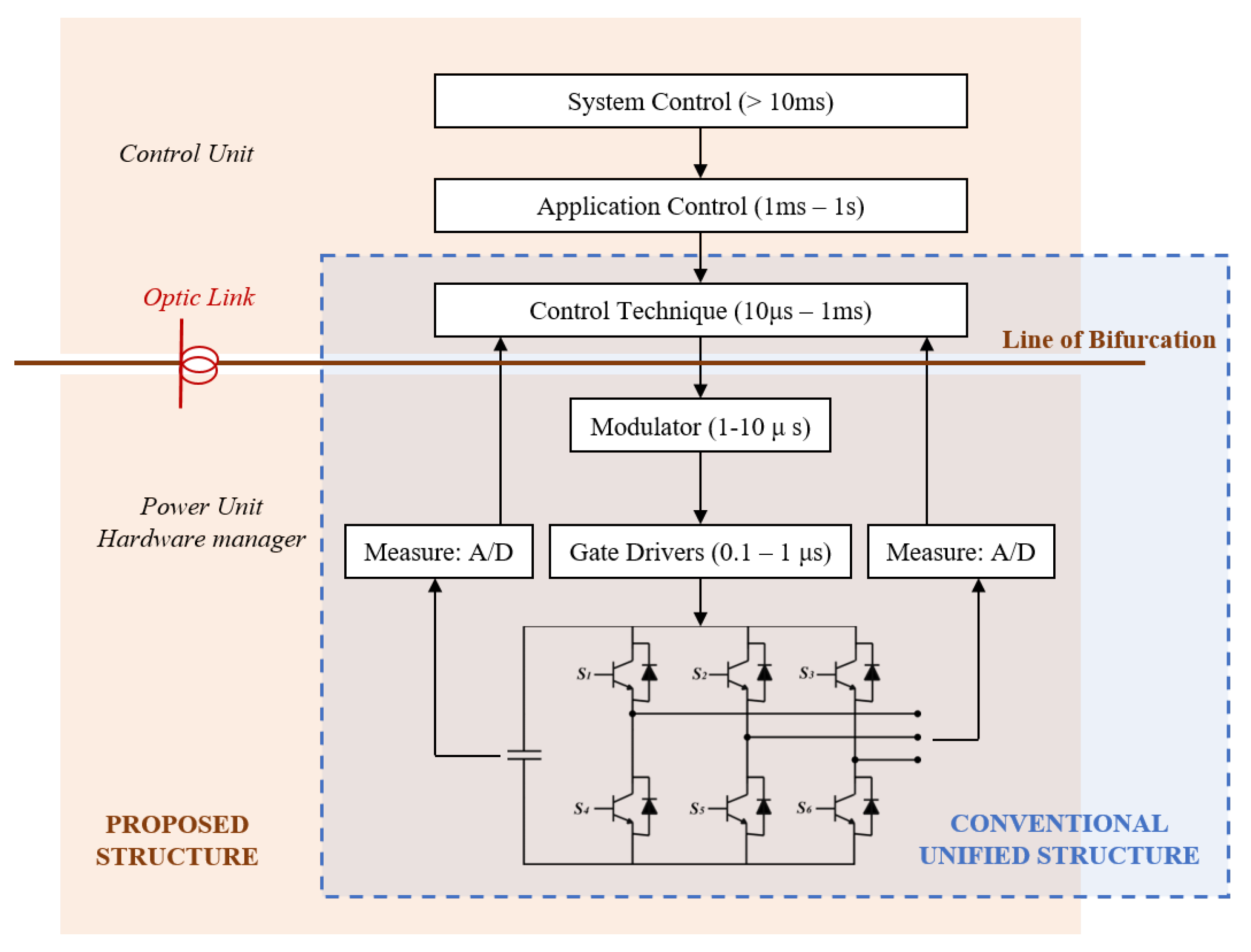
8], as reported in
Figure 1, following the organization by layers typical of data networks (e.g., ISO/OSI). The system control defines the objectives of the power electronic system and directs the functioning of application control layer towards that end. The converter layer subsystems that fall beneath the application control layer can be mimicked by a controlled current or a voltage source. The converter control layer implements the functions by determining the voltage references to be sent to the modulator (if any) of the switching control layer. The bottom-most hardware control layer manages the power devices.
A pertinent example is a wind farm where the power system operator (system control layer) dictates the required active and reactive power injection into the grid. The application control layer decides on the working of each individual wind turbine (converter control layer), considering the optimum efficiency, reliability, and maintenance.
It is emphasized that the latter two layers—switching and hardware control layer—are independent of the final application and are common for any PEC. This forms the basis of the replicable and modular PEBBs with minimum on-board intelligence. It implements the switching control functions and a communication link to an external controller, which, in turn, facilitates distributed control architectures and remote processing. A conventional PEC has a MicroController Unit (MCU) on-board for converter control, as depicted in
Figure 1. In the proposed structure, instead, the PEC ends with a switching controller, called the hardware manager in [
9], and delegates the converter control to an off-board control unit upstream via the optical communications link.
3. Photonic Bus: Implementation and Protocol
The photonic bus connects the Control Unit (CU) to several PECs relying on a daisy chain topology, through a bus made of a fiber pair. In the following, downstream refers to the command flow going from the CU to the PECs, while upstream refers to the data stream from PECs to the CU.
As commercially-available fibers and transceivers are targeted, a pair of optical fibers is employed—one fiber for upstreaming and the other for downstreaming—to connect the CU to the first PEC and each PEC to the following one. Such fiber pairs are widely commercially available from the main POF manufacturers and are directly compatible with transceiver OptoLocks. Couplers/splitters have been developed for POF, as well, thus allowing the use of a single fiber carrying both upstream and downstream transmission, but they are not commonly used due to larger penalties.
The daisy chain of many PECs is built using two transceivers on each PEC. Both downstream and upstream messages are received, decoded, and then forwarded to the next node. This happens down the chain for downstream messages or towards the CU for upstream messages. Each PEC has its own address in the bus, which is used to correctly receive messages from the CU or to tag the upstream data sent by the node. Given this decode-and-forward point-to-point structure, no collisions are expected in upstream transmission.
Besides the enumerated advantages, the photonic bus facilitates the integration with the cloud and thus follows the Internet of Things paradigm. As displayed in
Figure 2, the CU can be connected to an IP router to enable networking among several power electronic systems within a power electronic cloud distributed on the Internet, according to the paradigm of the Internet of Things. The daisy chain control bus, besides enabling a remotized control by the CU, may transport telemetry data that can be conveyed through the Internet upstream, or may deliver downstream the commands coming from the Internet to each PEC. Therefore, the power electronic systems are virtually placed within a cloud relying on the Internet data transport to connect systems to each other. Such a paradigm may enable the implementation of software-defined remote management and orchestration aimed at optimizing the management of different systems and orchestrating their collective effectiveness. Depending on the specific application, the orchestrator could also benefit from data from a cloud of users that may greatly help in optimizing the overall effectiveness of the power electronic cloud. An application field for which this approach could be largely beneficial is the generation of electricity from renewable sources. In this case, the power electronic systems are electricity generators—solar cells, wind turbines, etc.—and the users are families and companies delivering data on power consumption.
3.1. Description of the Protocol
Figure 3 describes the timing organization of the sampling and switching task. The switching frequency of the power devices dictates the sampling and switching period of the PEC. This is marked as
in
Figure 3, although not necessarily meaning that all PECs use pulse-width-modulation. Typical switching frequencies are in the order of 10–20 kHz, but the use of SiC power semiconductors is pushing these numbers higher, to 100 kHz or more in some cases.
At , the current flowing in the inverter legs, is sampled by the A/D converters on the power unit—the node—and is ready to be transmitted to the CU. The overall latency in transmitting () and receiving () packets is given by the time needed to perform the parallel-to-serial and serial-to-parallel conversions of the 66-bit words used by the 64/66 b line protocol used, plus the protocol encoding and decoding overhead, plus the latency introduced by the clock and data recovery logic. is the propagation time of the signal on the photonic bus. An extra latency Calc. has been reserved for the CU algorithm execution. Moreover, an idle extra time at the end of each cycle is required to check the correct update of the new PWM values before the following cycle starts.
The overall transmission time is defined as the one-way total time required by the data packet from one node to the other.
3.2. Transmission Overhead
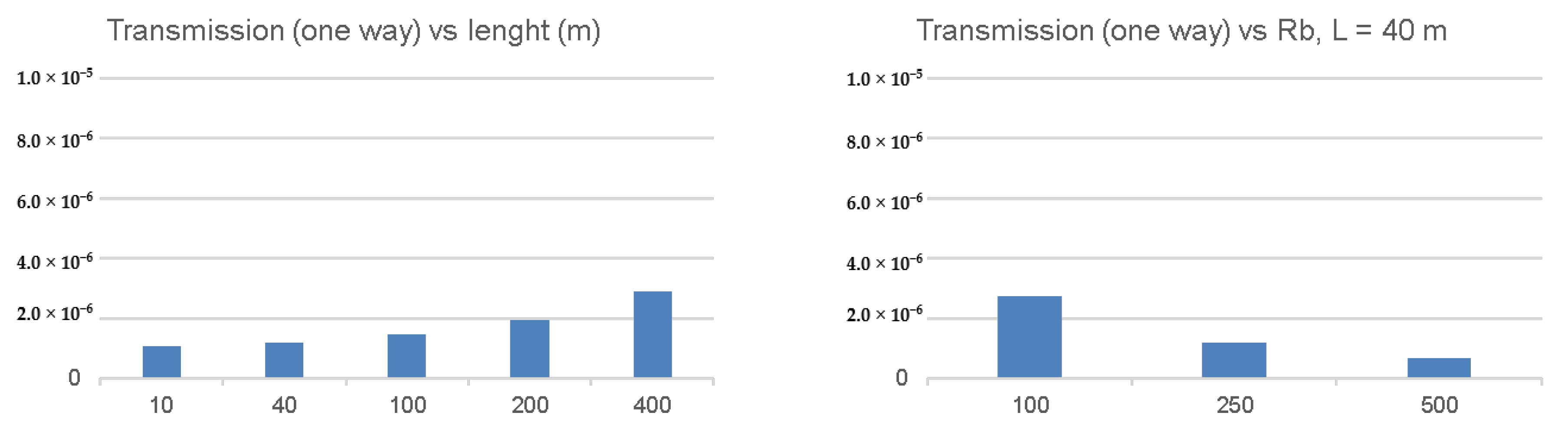
With respect to a standard PEC control scheme relying on an on-board MCU, the use of a remotized control through a photonic bus introduces an extra latency given by two-times the transmission time. Therefore, it is a firm request to keep the transmission time as negligible as possible, with respect to the switching period: a transmission time in the order of 1
s is considered negligible.
Figure 4 shows the ideal protocol performance, obtained considering only the bit-rate of transmission and the propagation time of light through the bus, without taking into account implementation-dependent latency overheads.
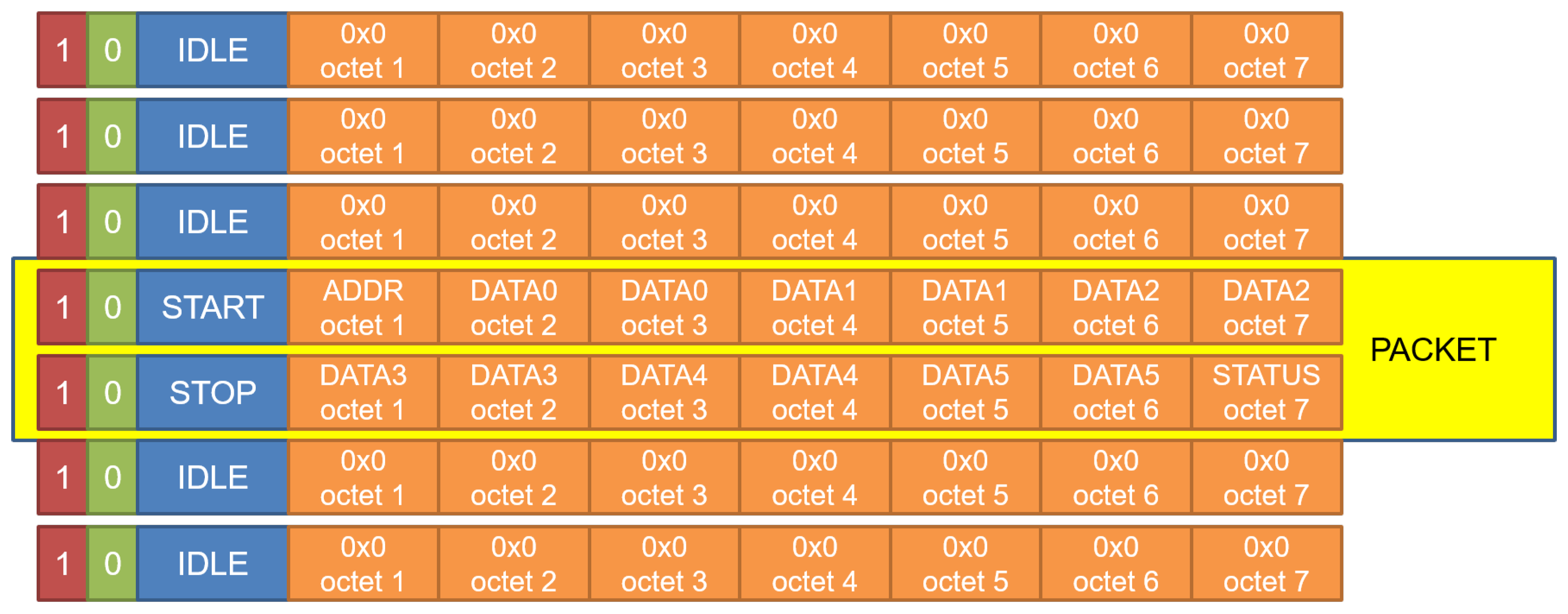
The proposed transmission protocol is based on 132-bit packets, encoded as a couple of consecutive 66-b words: the first word is tagged as /START (block field type 0x78); while, the second one is tagged as /STOP (block field type 0xFF). Therefore, each packet can carry up to 14 bytes of payload. The 66-b sync header is always set to “10”, i.e., control + data words.
Of these 14 bytes, the first one includes the node address in the daisy chain: destination node in the downstreaming from the CU to power nodes or the source node in upstreaming from the nodes to the CU. The last byte is used to read/set discrete I/O pins on the node itself. The remaining 12 bytes are organized as six 16-bit words: they contain ADC sampled data in the upstream channel and PWM duty-cycle values for downstreaming. Further extensions of the packet size must consider the rules of the line protocol, so they can be done adding 64-bit data words (66 bits when coded, marked with header “01”) between /START and /STOP frames. When data packets are not transmitted, the channel is filled with /IDLE words (block field 0x1E), as shown in
Figure 5.
4. Proof-of-Concept Demonstrator
In order to test the proposed photonic bus made of POF and the related communication protocol, we designed and experimentally realized a proof-of-concept demonstrator. For this experimental setup, in addition to the timing requirements explained in the previous section, the total cost and the relatively short fiber distance requirements are also considered. Costs and easy usage constraints have addressed the choice of an integrated, tool-less transceiver solution, commercially available and based on the OptoLock design. This choice allows establishing a connection by just cutting the fiber ribbon with a pair of scissors and locking it into the correct position. As short distances are targeted, the available optical bandwidth is adequate to carry the required rate on data. Hence, it is not necessary to reconstruct the transmitted waveform using A/D conversion and filtering implemented in digital signal processing [
14].
The fiber itself is a simple PMMA (Polymethyl Methacrylate) POF, standardized as A4a.2; it has a large core diameter (980 m) covered with a thin (10 m) layer of cladding. Therefore, it can be deployed without using specialized tools, but it has two main disadvantages: a large attenuation (180 dB/Km using red light at 650 nm, such as the one used by the transceivers we have chosen) and a low bandwidth length product (about 40 MHz per 100 m), which limits the possible maximum length and the maximum data rate.
The strict real-time requirements impeded relying on a forward error correction code as the Reed Solomon 237,255 used in [
14], limiting the link length to the 40 m at 250 Mb/s declared by the transceiver manufacturer. In order to operate the optical channel successfully, both DC balancing and an adequate data transition density are needed: these requirements are fulfilled by adopting a line code such as the 64/66 b. This line coding is widely adopted—e.g., in 10 G Ethernet—because it requires a 2-bit overhead over 64 bit words with a limited 3% overhead and enables a more efficient data transmission. Moreover, the transition density and the DC balancing are randomized by scrambling the data and control words with a known polynomial before optical transmission.
On the power unit, i.e., the remote node, a finite state machine takes care of handling PWM update and ADC sampling. On the control unit, as soon as a packet is received, an interrupt is raised, and the microcontroller core can access those values on five registers. These are memory mapped on a known location on the system Advanced eXtensible Interface (AXI) bus. Once the computation algorithm is completed, the updated values for the PWM are written on the registers of the transmit section, and the downstream packet is ready for sending to the target node. The first trials were performed sharing a single clock all over the network to synchronize transmitters and receivers. As a further development, a clock and data recovery section were added to each of the nodes to take care of the small frequency differences among nominally equal clock sources. Among all the possible clock and data recovery approaches, a fully-digital solution able to recover all the incoming bits was selected. The incoming asynchronous data stream was over-sampled at 4× its nominal rate, and the recovered bits were inserted in a FIFO, deep enough to account for small clock variations and jitter. As is typical for this solution, the receiver FIFO moved data from the asynchronous clock domain to the internal system clock. It can encounter an underflow when the clock on the receiver is slightly faster than the transmitter or overflows. The control logic solves these situations by adding/removing an IDLE word after the descrambling section of the 64/66-b decoder. This operation is safe because the optical bus is mainly filled with IDLE words with only occasional data packets: as we are dealing with a real-time control system, the performance bottleneck is not the available bandwidth, but the total latency.
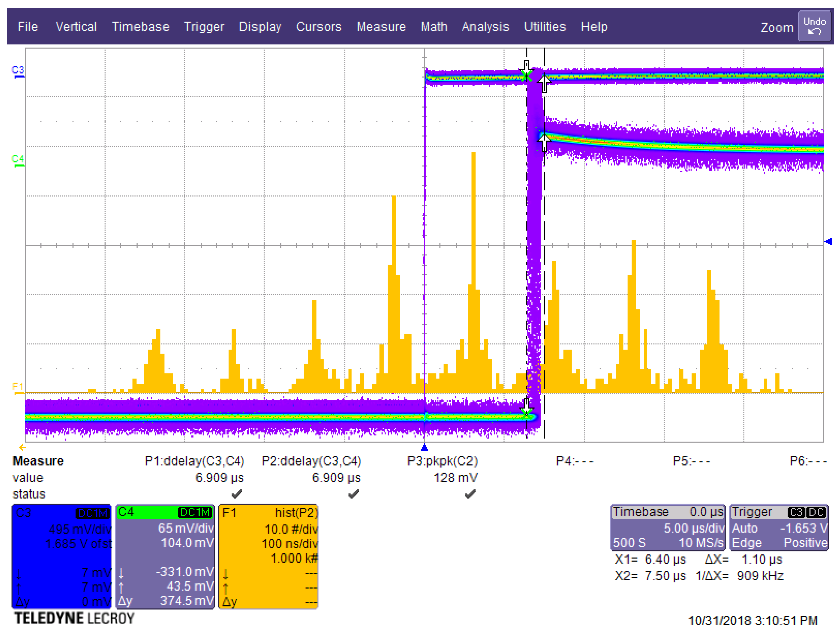
We experimentally measured the delay as the sum of
+
+
, shown in
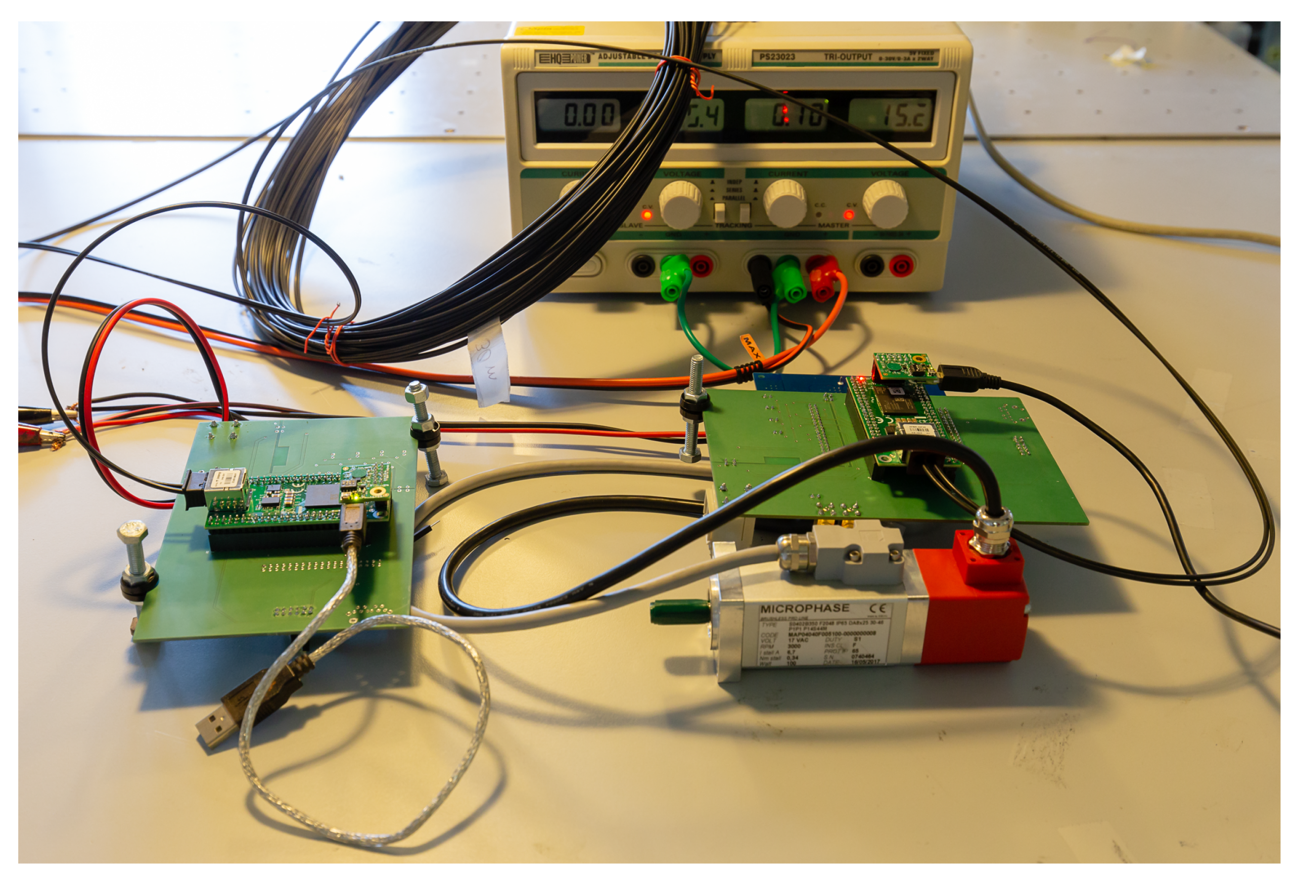
Figure 3, and the jitter introduced by our protocol on the system shown in
Figure 6. To these purposes, we used an oscilloscope and a simple test program that made a digital output pin switch on both the control unit and the remote unit. A visual comparisons of the oscilloscope outputs is displayed in
Figure 7.
Using a line rate of 250 Mbit/s and 40 m of POF fiber, we measured a delay of 6.9
s, significantly higher than what we expected from the VHDL simulations of the system. Looking at the detected jitter, we expect that the delay was caused by the FIFOs inserted between the different blocks: clock recovery, 16/64- and 64/66-b gearbox, output formatter, just to name some of the ones that were used. These introduced variable delays causing that “striped” pattern. Such a behavior cannot be simulated, because simulation time would be too long. Plots on
Figure 7 were obtained by setting the oscilloscope to infinite persistence and accumulating many minutes of observations.
The remote node was built around a commercial mini-module with a Xilinx Artix FPGA (San Jose, CA, USA), an integrated optical transceiver, and two 2.54 mm-spaced expansion slots. It was connected to the control unit by a 40-m POF pair. Relying on this setup, we successfully managed to control a three-phase voltage source inverter, used for vector control of a brushless servomotor. The system implemented on the remote node was very simple, because it was only made of two instances of the line protocol to communicate upstream to the control unit and downstream to a second node. Three PWM generators controlled the inverter; four SPI ports controlled the A/D section; and an FSM handled the data transfer. The implemented security was a watchdog to turn off PWM generation when communication with the host processor was lost. At the moment, overcurrent protection is provided by the supervisor only. The servomotor was rated at 100 W, 3000 rpm, and the PEC was a X-Nucleo-IHM08M1, a 60-V DC input, 15-A AC output expansion board for STM32 Nucleo boards by ST-Microelectronics. The PEC and servomotor were off-the-shelf equipment on purpose and had a small size, as the emphasis here was on demonstrating the real-time control capability via POF. A custom adapter board was developed to connect the FPGA module to an ST expansion board, adding also the A/D section needed to control the motor current, and to a second optical transceiver to daisy-chain more units. In
Table 1, we display the occupation of the Artix 100 device hosted on our minimodule: as the occupation is low, simpler (i.e., having a smaller FPGA) mini-modules were considered to lower the total remote module cost.
For the control unit, the first trials were performed with the same mini-module as the remote node by instantiating a full Microblaze microcontroller with a built-in floating-point unit running at 125 MHz. The control code was written using the standard C language, so it will be simply recompiled when targeting other cores; it has a small footprint (a few KB of RAM), and it can be executed from the embedded BRAM blocks present on the ARTIX device. The FPGA occupation reported by Vivado is shown in
Table 2.
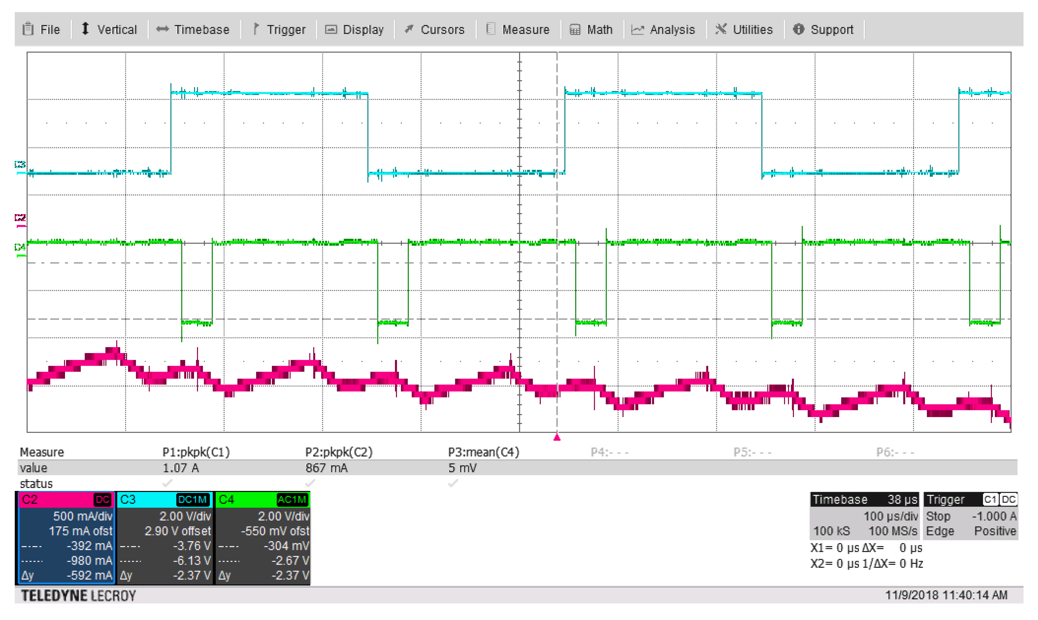
Validation was performed with a simple current vector control of a permanent magnet synchronous machine under no load, running at 500 rpm with a PWM switching frequency of 5 kHz. Using this sample code, we were able to re-create the results of
Figure 3, measuring the values directly on the oscilloscope. In
Figure 8, you can see three different waves: the cyan square wave is derived by the sampling timebase at 5 kHz, toggling a digital output pin at every sampling event; the green line shows the computation time of the motor control routine by the microcontroller (the output pin was kept low when the algorithm was running), which was around 30
s. The single-trip latency (from an edge of the cyan line to a falling edge of the green line), which accounts for the ADC conversion and read time, communication protocol, propagation time, and microprocessor latency, was around 13
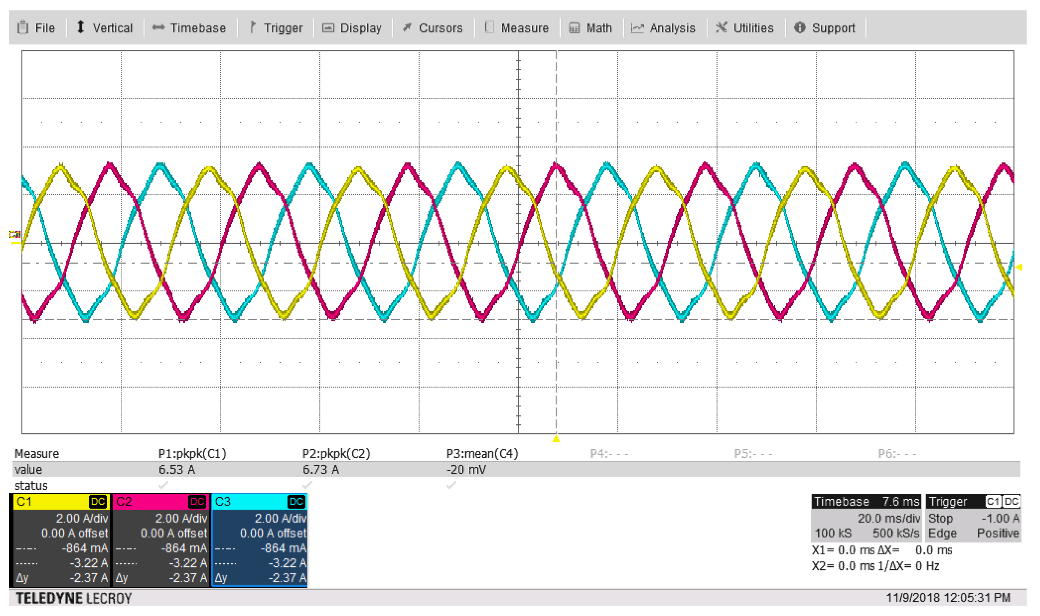
s. The purple line is the current on one of the motor phases, measured with a current probe. The steady-state three-phase currents of the motor are shown in
Figure 9.
The second set of trials will run on a commercial board with a higher performance Xilinx Zynq XC7Z010 FPGA: such a component is suitable for our prototyping purposes, having on board both FPGA resources (needed for the real-time optical communication) and a real 600+-MHz ARM A9 core with its embedded peripherals; the optical transceiver will be added on a custom board using an expansion connector.
Further work will follow two directions. The first will be enhancing the system security and availability, adding fail-safe features to protect the users and the hardware against communication failures. The second will see the implementation of advanced control algorithms on the higher performance ARM platform, enabling smarted power conversion, and the telemetry section needed to upload working data on a cloud data pool, making remote monitoring and fault analysis feasible.

 and
and 


