Software Defined Networks in Industrial Automation


Abstract
:1. Introduction
1.1. Software Defined Network
1.2. Brief History of Industrial Networks
1.3. SDNs in Industrial Automation
1.4. Contributions
- We investigate the research gap that exists for IP-based networking in industrial automation and introduce a novel industrial network framework based on an SDN communication architecture.
- We propose two solutions for flow creation in relieving the incurred overhead due to the flow setup cost in SDN.
- We render an optimal latency model based on a meticulous flow analysis using -Norm Optimization to calculate the shortest path. It verifies the quantified model using a Monte Carlo simulation.
- We validate the proposed scheme by running an experiment in an emulated environment using Mininet [22].
- We exploit the merits of the proposed framework by presenting an ongoing test bed implementation. The investigation is conducted on a food processing demonstrator.
1.5. Paper Organization
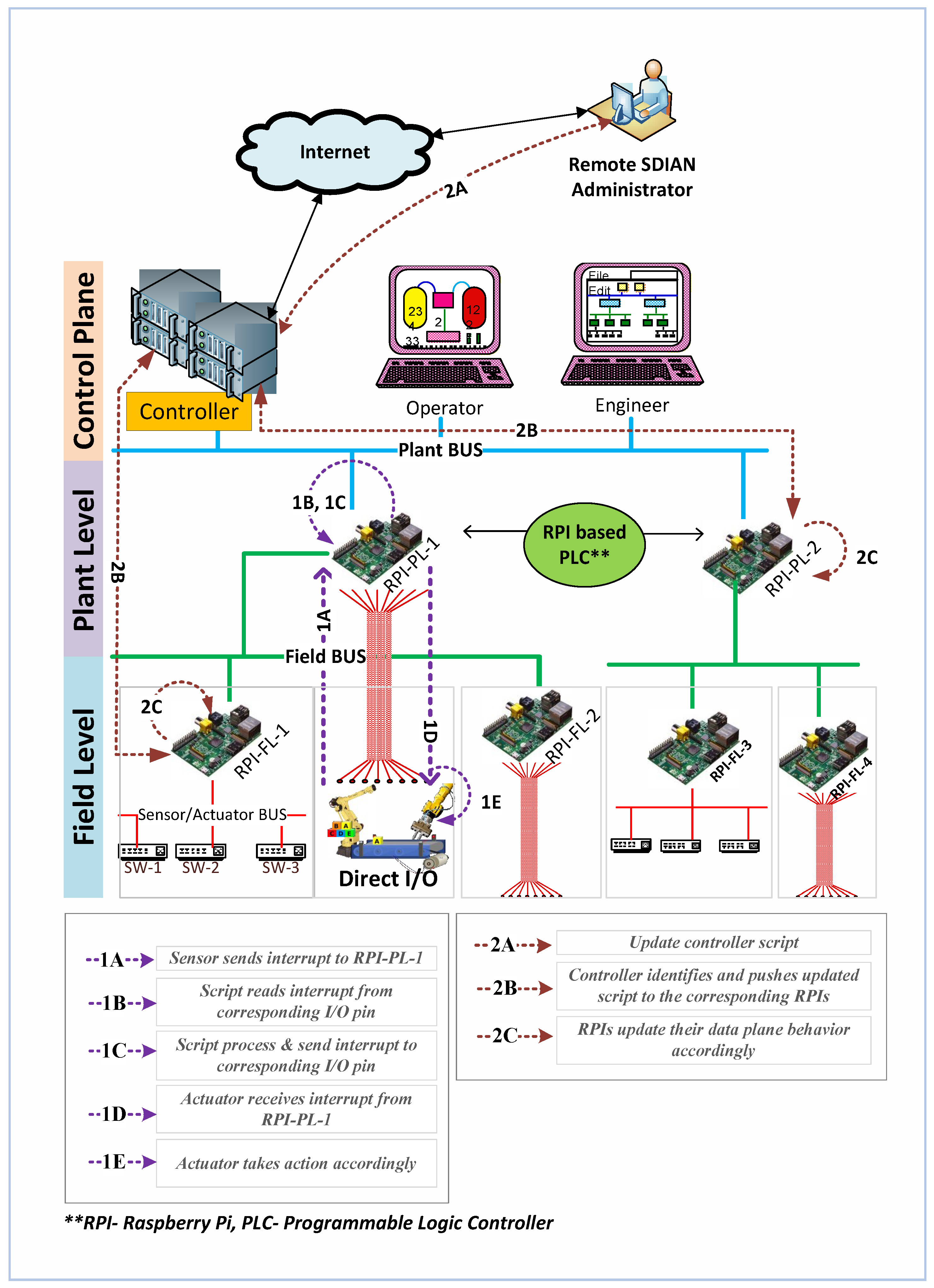
2. Architecture and Framework
2.1. System Model
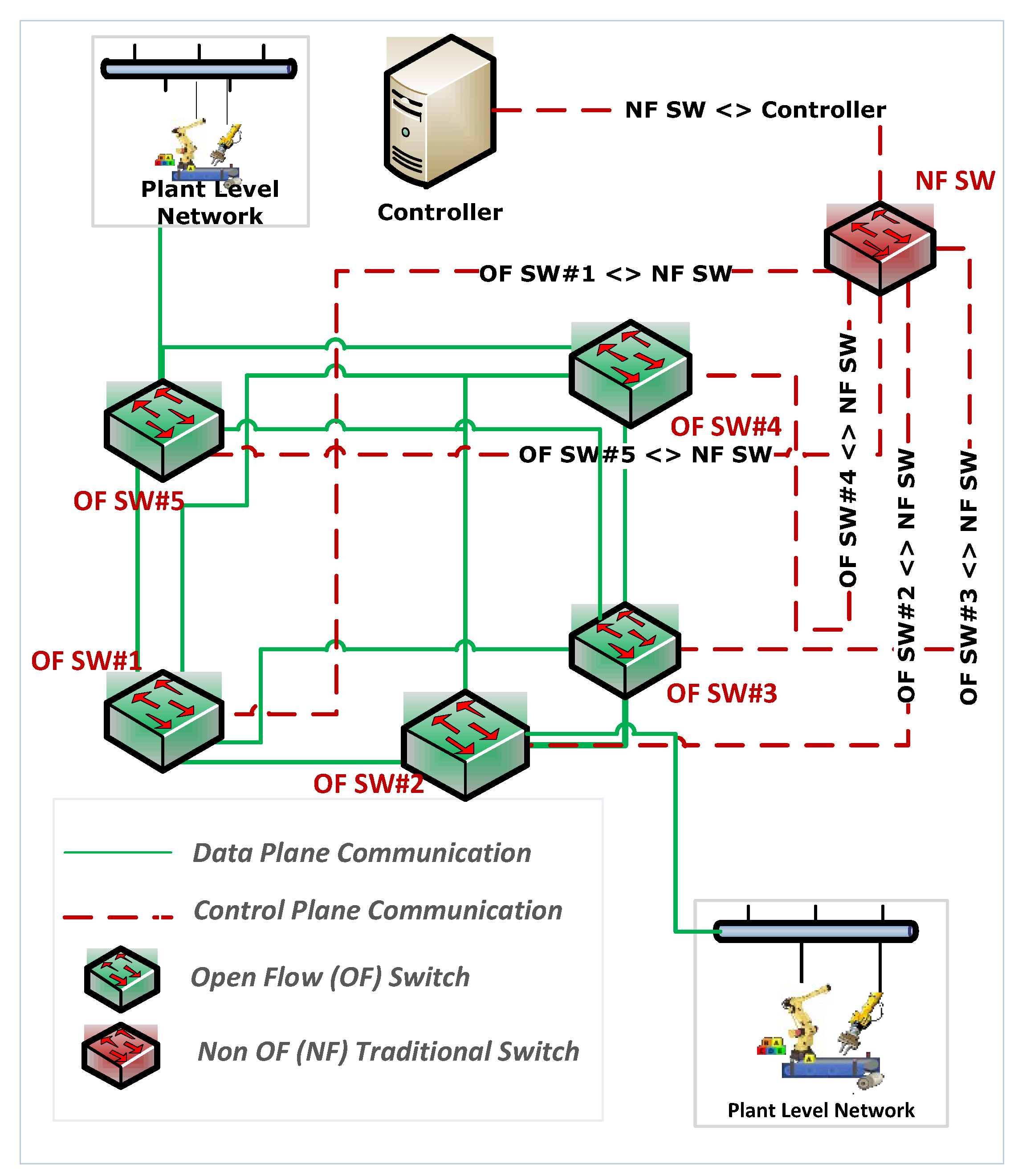
2.2. SDIAN Communication Framework
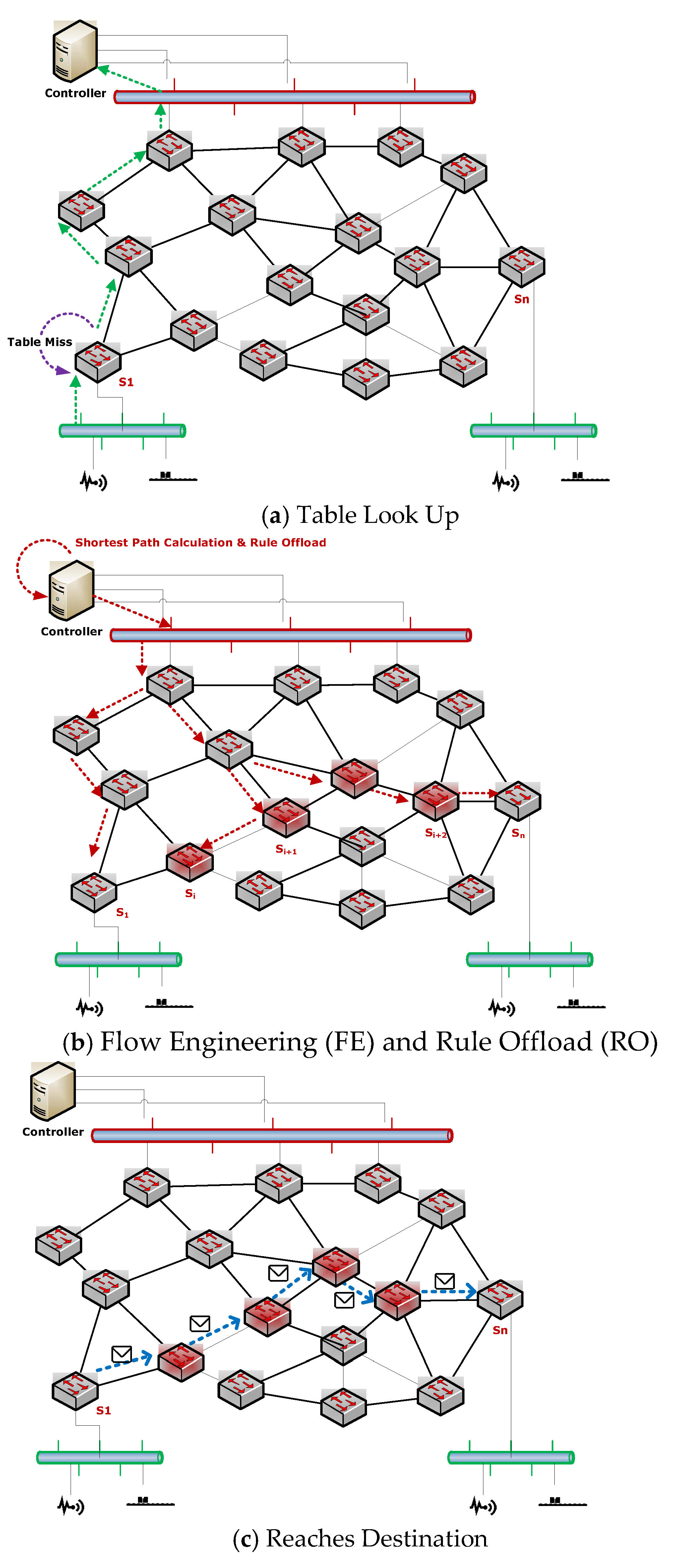
2.3. Creating Flows
3. Flow Analysis
3.1. Data Layer: Basic Notations
Shortest Path Routing (L1-Norm Optimization)
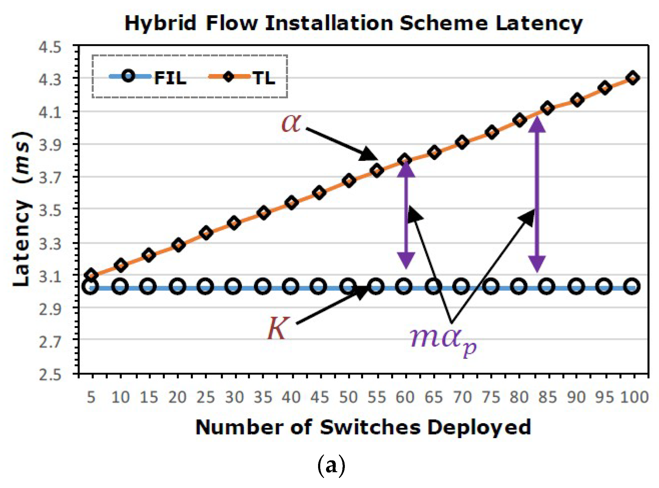
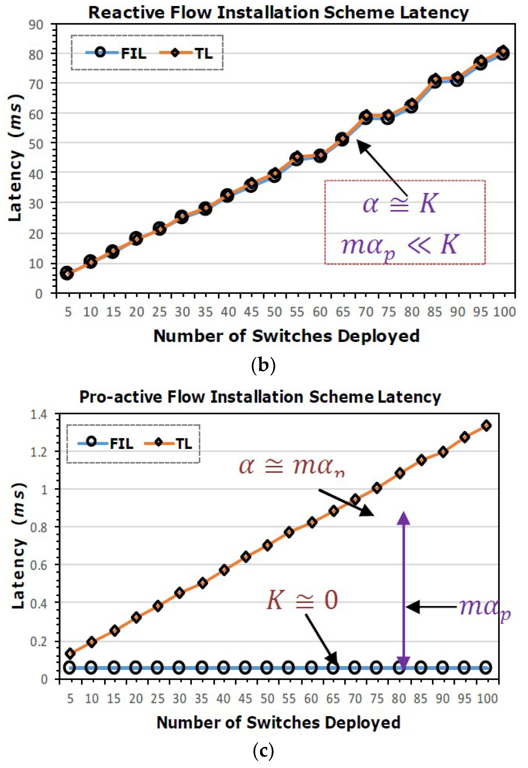
3.2. Optimal Latency Model: Hybrid
3.3. Optimal Latency Model: Pro-Active
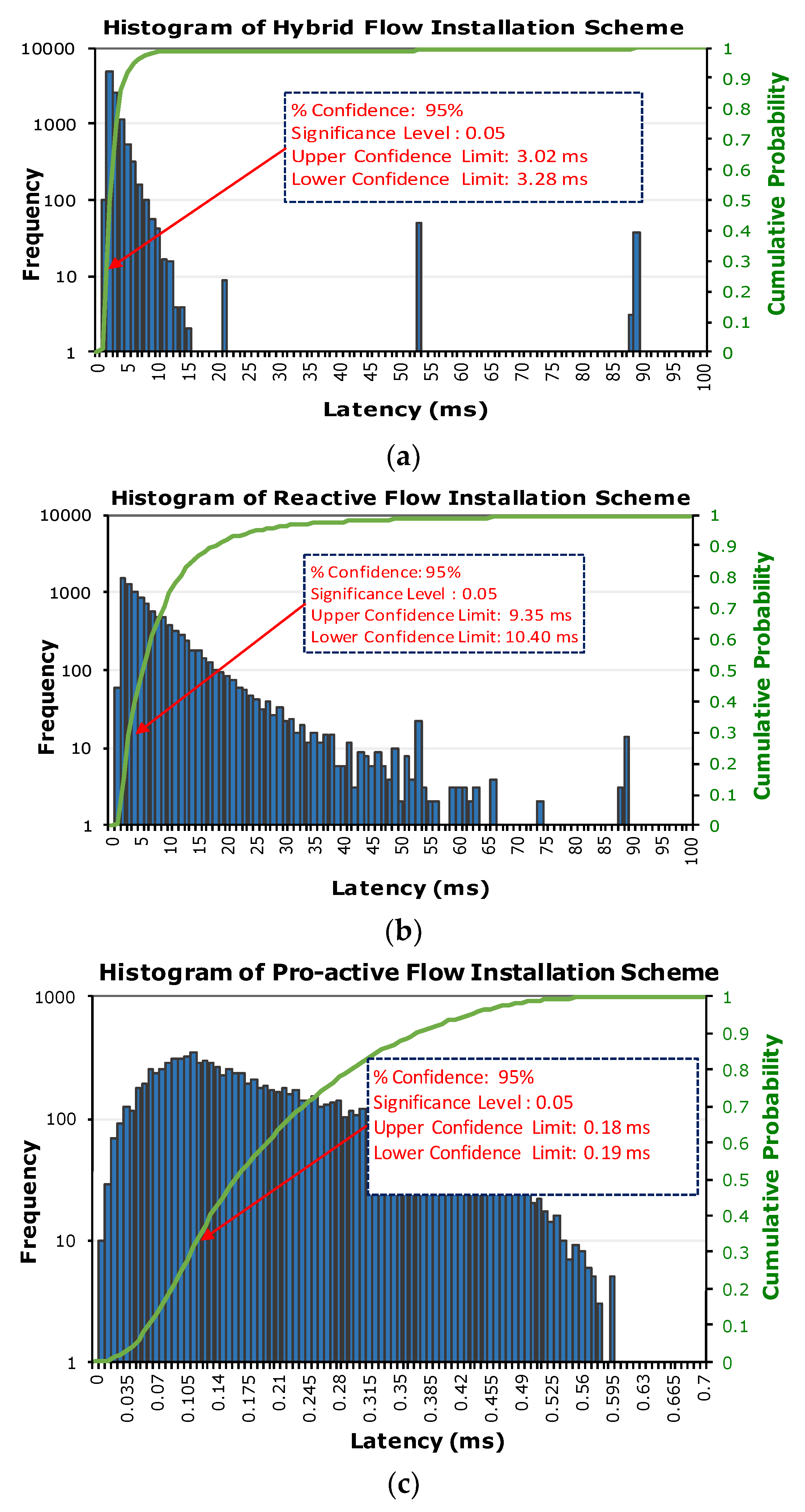
4. Stochastic Analysis of SDIAN
Discussion
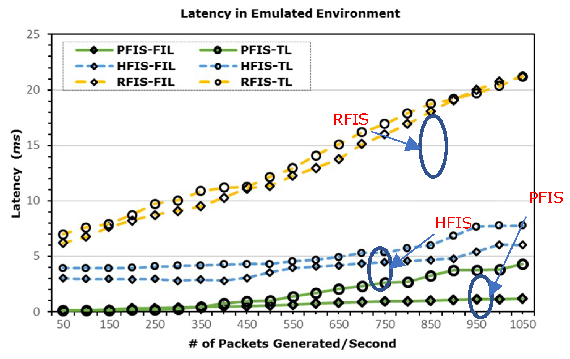
5. Experiments
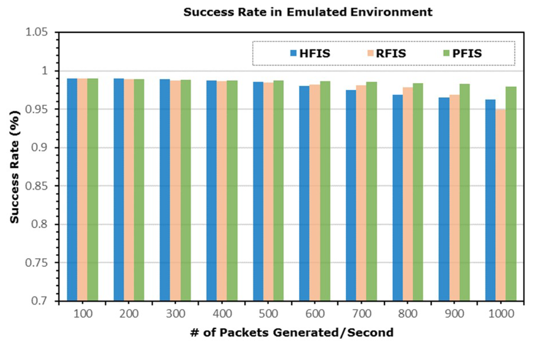
5.1. Emulation Environment
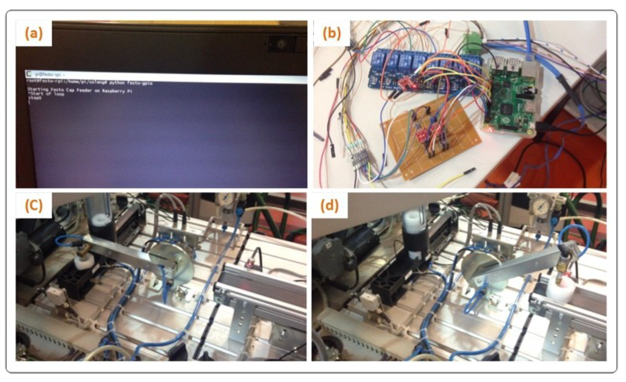
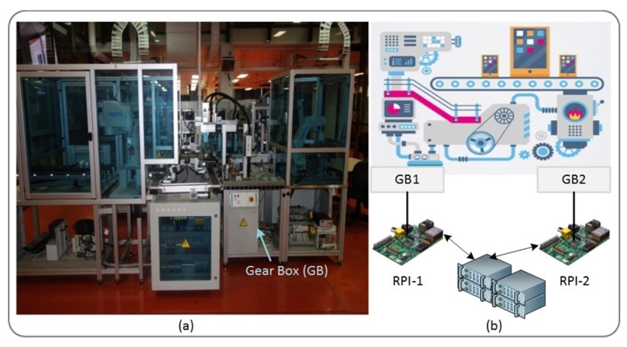
5.2. Test Bed Implementation
6. Conclusions
Supplementary Materials
Author Contributions
Funding
Acknowledgments
Conflicts of Interest
References
- Xia, W.; Wen, Y.; Foh, C.H.; Niyato, D.; Xie, H. A Survey on Software-Defined Networking. IEEE Commun. Surv. Tutor. 2015, 17, 27–51. [Google Scholar] [CrossRef]
- Huang, T.; Yu, F.R.; Zhang, C.; Liu, J.; Zhang, J.; Liu, J. A Survey on Large-scale Software Defined Networking (SDN) Testbeds: Approaches and Challenges. IEEE Commun. Surv. Tutor. 2016, 19. [Google Scholar] [CrossRef]
- Hu, F.; Hao, Q.; Bao, K. A Survey on Software-Defined Network and OpenFlow: From Concept to Implementation. IEEE Commun. Surv. Tutor. 2014, 16, 2181–2206. [Google Scholar] [CrossRef]
- Raghavan, B.; Casado, M.; Koponen, T.; Ratnasamy, S.; Ghodsi, A.; Shenker, S. Software-defined internet architecture: Decoupling architecture from infrastructure. In Proceedings of the 11th ACM Workshop on Hot Topics in Networks, Redmond, WA, USA, 29–30 October 2012. [Google Scholar]
- Skeie, T.; Johannessen, S.; Holmeide, O. Timeliness of real-time IP communication in switched industrial Ethernet networks. IEEE Trans. Ind. Inform. 2006, 2, 25–39. [Google Scholar] [CrossRef]
- Decotignie, J.D. Ethernet-Based Real-Time and Industrial Communications. Proc. IEEE 2005, 93, 1102–1117. [Google Scholar] [CrossRef] [Green Version]
- Rojas, C.; Morell, P.; Sales, D.E. Guidelines for Industrial Ethernet infrastructure implementation: A control engineer’s guide. In Proceedings of the 2010 IEEE-IAS/PCA 52nd Cement Industry Technical Conference, Colorado Springs, CO, USA, 28 March–1 April 2010; pp. 1–18. [Google Scholar]
- Gungor, V.C.; Hancke, G.P. Industrial Wireless Sensor Networks: Challenges, Design Principles, and Technical Approaches. IEEE Trans. Ind. Electron. 2009, 56, 4258–4265. [Google Scholar] [CrossRef] [Green Version]
- Hou, L.; Bergmann, N.W. Novel Industrial Wireless Sensor Networks for Machine Condition Monitoring and Fault Diagnosis. IEEE Trans. Instrum. Meas. 2012, 61, 2787–2798. [Google Scholar] [CrossRef]
- Kopetz, H.; Ademaj, A.; Grillinger, P.; Steinhammer, K. The time-triggered Ethernet (TTE) design. In Proceedings of the Eighth IEEE International Symposium on Object-Oriented Real-Time Distributed Computing (ISORC’05), Seattle, WA, USA, 18–20 May 2005; pp. 22–33. [Google Scholar]
- Cronberger, D. Software Defined Networks. 2015. Available online: http://www.industrial-ip.org/en/industrial-ip/convergence/software-defined-networks (accessed on 20 July 2018).
- RAMI 4.0. Retrieved in August 2017. Available online: https://www.zvei.org/en/subjects/industry-4-0/thereference-architectural-model-rami-40-and-the-industrie-40-component/ (accessed on 20 July 2018).
- IIRA. Retrieved in August 2017. Available online: http://www.iiconsortium.org/ (accessed on 20 July 2018).
- Ahmed, K.; Blech, J.O.; Gregory, M.A.; Schmidt, H. Software Defined Networking for Communication and Control of Cyber-Physical Systems. In Proceedings of the 2015 IEEE 21st International Conference on Parallel and Distributed Systems (ICPADS), Melbourne, VIC, Australia, 14–17 December 2015; pp. 803–808. [Google Scholar]
- Li, D.; Zhou, M.T.; Zeng, P.; Yang, M.; Zhang, Y.; Yu, H. Green and reliable software-defined industrial networks. IEEE Commun. Mag. 2016, 54, 30–37. [Google Scholar] [CrossRef]
- Cronberger, D. The software defined industrial network. Ind. Ethernet Book 2014, 84, 8–13. [Google Scholar]
- Kalman, G.; Orfanus, D.; Hussain, R. Overview and future of switching solutions for industrial Ethernet. Int. J. Adv. Netw. Serv. 2014, 7, 206–215. [Google Scholar]
- Schweissguth, E.; Danielis, P.; Niemann, C.; Timmermann, D. Application-aware Industrial Ethernet Based on an SDN-supported TDMA Approach. In Proceedings of the 2016 IEEE World Conference on Factory Communication Systems (WFCS), Aveiro, Portugal, 3–6 May 2016. [Google Scholar]
- Henneke, D.; Wisniewski, L.; Jasperneite, J. Analysis of realizing a future industrial network by means of Software-Defined Networking (SDN). In Proceedings of the 2016 IEEE World Conference on Factory Communication Systems (WFCS), Aveiro, Portugal, 3–6 May 2016. [Google Scholar]
- Schneider, B.; Zoitl, A.; Wenger, M.; Blech, J.O. Evaluating Software-Defined Networking for Deterministic Communication in Distributed Industrial Automation Systems. In Proceedings of the 2017 22nd IEEE International Conference on Emerging Technologies and Factory Automation (ETFA), Limassol, Cyprus, 12–15 September 2017. [Google Scholar]
- Ahmed, K.; Nafi, N.S.; Blech, J.O.; Gregory, M.A.; Schmidt, H. Software defined industry automation networks. In Proceedings of the 2017 27th International Telecommunication Networks and Applications Conference (ITNAC), Melbourne, VIC, Australia, 22–24 November 2017; pp. 1–3. [Google Scholar]
- Open Networking Fundation. Software-Defined Networking: The New Norm for Networks. Available online: https://www.opennetworking.org/images/stories/downloads/sdn-resources/white-papers/wp-sdn-newnorm.pdf (accessed on 5 March 2018).
- Opennetworking.org. OpenFlow—Open Networking Foundation. 2016. Available online: https://www.opennetworking.org/sdn-resources/openflow (accessed on 10 April 2018).
- Kelly, F.P. Network routing. Philos. Trans. R. Soc. Lond. A Math. Phys. Eng. Sci. 1991, 337, 343–367. [Google Scholar] [CrossRef]
- Yufei, W.; Zheng, W.; Leah, Z. Internet traffic engineering without full mesh overlaying. In Proceedings of the INFOCOM 2001. Twentieth Annual Joint Conference of the IEEE Computer and Communications Societies, Anchorage, AK, USA, 22–26 April 2001; Volume 1, pp. 565–571. [Google Scholar]
- Li, Y.; Zhang, Z.L.; Boley, D. From Shortest-Path to All-Path: The Routing Continuum Theory and Its Applications. IEEE Trans. Parallel Distrib. Syst. 2014, 25, 1745–1755. [Google Scholar] [CrossRef] [Green Version]
- He, K.; Khalid, J.; Gember-Jacobson, A.; Das, S.; Prakash, C.; Akella, A.; Li, L.E.; Thottan, M. Measuring control plane latency in SDN-enabled switches. In Proceedings of the 1st ACM SIGCOMM Symposium on Software Defined Networking Research, Santa Clara, CA, USA, 17–18 June 2015. [Google Scholar]
- Blenk, A.; Basta, A.; Zerwas, J.; Reisslein, M.; Kellerer, W. Control Plane Latency With SDN Network Hypervisors: The Cost of Virtualization. IEEE Trans. Netw. Serv. Manag. 2016, 13, 366–380. [Google Scholar] [CrossRef]
- Community, R.S.F. Ryu SDN Framework. 2014. Available online: https://osrg.github.io/ryu/ (accessed on 10 April 2018).


| Industrial Communication Protocols | Computer Networks | |||||||
|---|---|---|---|---|---|---|---|---|
| Protocol Name | Published by | Place | Com. Tech | Year | Protocol Name | Year | ||
| Modbus | Modular Bus | Modicon (now Schneider Electric) | United States | Master/Slave | 1979 | 1970–1980 | ARPANET | 1970 |
| Ethernet | 1973 | |||||||
| ISO/OSI | 1978 | |||||||
| PROWAY | Process Data Highway | Working Group 6 | 1981 | 1981–1990 | MAP | 1980 | ||
| FIP | French Initiatice | factory instrumentation protocol | France | Producer/Consumer | 1982 | |||
| Bitbus | BIT Fieldbus | Intel Corporation | USA | Master/Slave | 1983 | |||
| HART | Highway Addressable Remote Transducer | FieldComm Group | USA | Master/Slave | 1985 | Internet | 1981 | |
| CAN | Controller Area Network | Robert Bosch GmbH | Detroit, Michigan | Producer/Consumer, Peer to Peer | 1985 | |||
| P-NET | Process Network | Process-Data Silkeborg ApS | Denmark | Master/Slave | 1987 | MMS | 1985 | |
| INTERBUS | INTERBUS | Phoenix Contact | Germany | Master/Slave | 1987 | |||
| PROFIBUS | The Federal Ministry of Education and Research (BMBF) | process field bus | Germany | Master/Slave, Peer to Peer | 1989 | Ubiq. Comp | 1988 | |
| EIB | European Installation Bus (EIB) | EIB Association | Europe | Master/Slave | 1991 | 1991–2000 | WWW | 1992 |
| Asi | Actuator Sensor Interface | AS-International | Germany | Master/Slave | 1992 | |||
| SDS | Smart Distributed System | Honeywell | USA | Master/Slave | 1993 | 2G GSM | 1996 | |
| DeviceNet | Connecting Devices | Allen-Bradley | USA | Producer/Consumer | 1993 | |||
| FF | WLAN | 1997 | ||||||
| ControlNet | Real-Time Control Network | Rockwell Automation | USA | Producer/Consumer | 1995 | |||
| TTP | Time-Triggered-Protocol | Vienna University of Technology | Vienna, Austria | Master/Slave | 1998 | IoT | 1997 | |
| Powerlink | Ethernet Powerlink | B&R Industrial Automation GmbH | Austria | Producer/Consumer | 2001 | 2001–2010 | Bluetooth | 2003 |
| Modbus/TCP | Modbus RTU protocol with a TCP interface that runs on Ethernet | Modicon (now Schneider Electric) | United States | Master/Slave | 2001 | SOAP | 2003 | |
| PROFINET | Process Field Net | Profibus & PROFINET International | Germany | Real-Time Ethernet | 2001 | 3G: UMTS | 2001 | |
| EtherCAT | Ethernet for control automation technology | Beckhoff Automation | Germany | Master/Slave | 2003 | ZigBee | 2003 | |
| ISA 100.11a | Wireless Systems for Industrial Automation | International Society of Automation | Worldwide | NIL | 2009 | 3G: HSPA | 2005 | |
| UWB | 2008 | |||||||
| Wire. HART | Wireless HART | HART Communication Foundation | USA | Master/Slave | 2007 | 6loWPAN | 2009 | |
| 4G: LTE | 2010 | |||||||
| Framework/Concept | Brief Description | Year Published |
|---|---|---|
| Software Defined Industrial Network [16] | Reflects the possibility of bringing programming capability in industrial network through the use of SDN. A theoretical framework is provided | 2014 |
| Outlook on Future Possibilities [17] | Possible evolution of industrial Ethernet using SDN | 2014 |
| SDNPROFINET [14] | Proposed to transform the typical communication architecture of PROFINET integrating SDN | 2015 |
| SDN-based TDMA in IE [18] | SDN approach is used to formulate an application-aware Industrial Ethernet Based on TDMA | 2016 |
| SDIN [15] | Propose a new Software Defined Industry Network (SDIN) architecture to achieve high reliability, low latency, and low energy consumption in Industrial Networks | 2016 |
| Challenge and Opportunities [19] | Prospect of future industrial network by means of SDN | 2016 |
| Direct Multicast Routing [20] | Evaluates SDN for deterministic communication in distributed industrial automation systems | 2017 |
| SDIAN [21] | Software-defined industry automation networks | 2017 |
| Component | Task | Layer |
|---|---|---|
| RPi | Receive and send interrupt to sensors and actuators | Data Plane |
| Sensors | Sends an interrupt to an associated RPi immediately after sensing an object | Data Plane |
| Actuators | Executes the explicitly specified action immediately after receiving an interrupt from RPi | Data Plane |
| Southbound Interface (SBI) | Interface between data and controller plane. The functions realized through this interface include, but not limited to: (i) programmatic control of all forwarding operations (ii) monitoring (iii) network statistics (iv) advertisement and (v) event notification | Between Control and Data Plane |
| Controller | Manage/control network services. It consists of NBI and SBI agents and control logic. A logically centralized but physically distributed | Control Pane |
| Northbound Interface (NBI) | Interface between application and controller plane. It typically provides an abstract view of the network and enables direct expression of network requirements and behavior | Between Application and Control Plane |
| Applications | Programs in execution that explicitly translate the business use case, network requirements and, behavior programmatically and logically to the controller | Application Plane |
| Sample Size | HFIS | RFIS | PFIS | |
|---|---|---|---|---|
| 10,000 | 10,000 | 10,000 | ||
| Central Tendency | Mean | 3.15533 | 9.84786 | 0.19091 |
| Median | 2.03766 | 5.40382 | 0.163 | |
| StErr | 0.06706 | 0.27245 | 0.00119 | |
| Spread | StDev | 6.7095 | 26.7239 | 0.1189 |
| Max | 88.7062 | 883.67201 | 0.598 | |
| Min | 0.6773 | 0.6773 | 0.003 | |
| Range | 88.0288 | 882.9946 | 0.595 | |
| Q(0.75) | 3.0157 | 10.2242 | 0.264 | |
| Q(0.25) | 1.5196 | 2.7774 | 0.098 | |
| Q Range | 1.4960 | 7.4467 | 0.166 | |
| Shape | Skewness | 10.3932 | 15.9369 | 0.8368 |
| Kurtosis | 118.0304 | 330.8579 | 0.0093 | |
| Quantiles, Percentiles, Intervals | 90% Interval | Q(0.05) = 1.17 | Q(0.05) = 1.34 | Q(0.05) = 0.04 |
| Q(0.95) = 6.01 | Q(0.95) = 24.9 | Q(0.95) = 0.42 | ||
| 95% Interval | Q(0.025) = 1.08 | Q(0.025) = 1.22 | Q(0.025) = 0.03 | |
| Q(0.975) = 7.84 | Q(0.975) = 35.61 | Q(0.975) = 0.47 | ||
| 95% CI for the Mean | Upper Limit | 3.0210 | 9.5795 | 0.1883 |
| Lower Limit | 3.2839 | 10.7175 | 0.1930 | |
© 2018 by the authors. Licensee MDPI, Basel, Switzerland. This article is an open access article distributed under the terms and conditions of the Creative Commons Attribution (CC BY) license (http://creativecommons.org/licenses/by/4.0/).
Share and Cite
Ahmed, K.; Blech, J.O.; Gregory, M.A.; Schmidt, H.W. Software Defined Networks in Industrial Automation. J. Sens. Actuator Netw. 2018, 7, 33. https://doi.org/10.3390/jsan7030033
Ahmed K, Blech JO, Gregory MA, Schmidt HW. Software Defined Networks in Industrial Automation. Journal of Sensor and Actuator Networks. 2018; 7(3):33. https://doi.org/10.3390/jsan7030033
Chicago/Turabian StyleAhmed, Khandakar, Jan O. Blech, Mark A. Gregory, and Heinz W. Schmidt. 2018. "Software Defined Networks in Industrial Automation" Journal of Sensor and Actuator Networks 7, no. 3: 33. https://doi.org/10.3390/jsan7030033
APA StyleAhmed, K., Blech, J. O., Gregory, M. A., & Schmidt, H. W. (2018). Software Defined Networks in Industrial Automation. Journal of Sensor and Actuator Networks, 7(3), 33. https://doi.org/10.3390/jsan7030033