1. Introduction
With the rapid expansion of Machine to Machine (M2M) communication and Internet of Things (IoT) applications in different domains, such as smart city, smart grid, healthcare, and environmental monitoring, the need for the development of low-cost, energy-efficient reliable area network architectures is increasing [
1]. For M2M and IoT applications, communication area networks play a very important role in moving data between various sensors, actuators, servers, and controllers. Many such applications will operate either in real-time or in delay-bounded conditions. For smart city and smart grid applications, network entities or devices, such as sensors, actuators, and controllers could be distributed over large geographical areas where devices could be located either in indoor or outdoor environments. In outdoor deployments, reliable data communication could be a challenging task due to the distributed nature of the system, heterogeneous radio propagation environments, as well as variable traffic conditions [
2]. At the same time, communication service requirements for the M2M/IoT applications are different compared to traditional data networks. Questions might arise, such as why should we consider the communication needs of M2M and IoT systems together? Traditionally M2M solutions typically use point-to-point links using wired or wireless connectivity. On the other hand, IoT solutions rely on Internet Protocol (IP) networks to interface data to a cloud or middleware platform. M2M communication is more concerned with the lower-level networking functionalities [
3]. The IoT represents connectivity beyond transmission from one machine to another. Obviously there is a certain overlap between these two systems; that is, the need to use lower-level network protocols and architecture. Hence, we explore the communication needs for both systems. Key requirements of IoT applications are listed below:
Need to serve medium to high network device density (devices/sq.km), generating small bursts of data with variable duty cycle.
Low energy availability for computing and communication needs.
Very high reliability with variable Quality of Service (QoS) requirements.
Low, or no, terminal mobility.
Asymmetric traffic flow with higher capacity requirements on the uplink (i.e., from an end device to a network-based data sink).
To serve distributed IoT applications with the above requirements, different wireless network architectures can be used. Traditional cellular wide area networks could be used to support such applications which generally have higher capital expenditure (CAPEX) and operational expenditure (OPEX) costs. Another approach could be to use unlicensed band short range wireless networks where multi-hop or mesh wireless network architecture can be used to cover large geographical areas. Traditional cellular networks, such as 3G/4G-based standards may not efficiently support all of the needs of IoT applications due to high signaling requirements, infrastructure, and energy costs [
4]. Additionally, cellular networks may not provide seamless connectivity to all devices due to spatial and temporal fading effects. The M2M communications functional model proposed by the European Telecommunications Standards Institute (ETSI) standard suggests that cellular networks could provide core network support and aggregated data from gateways could be transmitted over cellular networks [
5]. Hence, to support the device level communication, it is necessary to develop a new wireless sensor network architecture that can deliver QoS requirements for different applications. The two main drawbacks of traditional wireless sensor networks are lack of deterministic QoS support and the scalability problem [
6].
The main contribution of this paper is a new low-cost heterogeneous network architecture that can support IoT data transmission needs in a wide area with the necessary QoS requirements. The heterogeneous wireless network architecture has been developed to operate in the unlicensed band where inter and intra-network interferences could be a critical problem. This proposed architecture introduces a new inter network cooperative medium access control (MAC) layer-based signaling protocol to mitigate the above interference problem and to improve the throughput of an M2M area network based on short range wireless networking standards.
The objective of the paper is to present new directions on the low-cost wide area network design for M2M and IoT applications using unlicensed band standards. The paper structure is as follows:
Section 2 briefly reviews typical smart city IoT and M2M communication requirements.
Section 3 reviews M2M communication network architectures and requirements;
Section 4 discusses M2M area network design issues and reviews the IEEE 802.15.4 and IEEE 802.11 networking standards for the area network design;
Section 5 presents a new IPv6 Low power Wireless Personal Area Network 6LoWPAN) and IEEE 802.11 standards-based heterogeneous M2M area network architecture where the coexistence problem is mitigated by using a cooperative MAC protocol;
Section 6 presents extensive simulation results and performance analysis obtained from a custom OPNET (Optimized Network Engineering Tool)-based simulation model; and conclusions are drawn in
Section 7.
2. IoT Communication Requirements for Smart City Applications
IoT is one of the distributed computing areas where a large number of applications are appearing in different domains, such as smart city, smart grid, e-health, vehicular communications, etc. [
7,
8]. One of the key requirements of IoT applications is to move data between different entities in an autonomous manner by using the lower-level M2M communication architecture. The QoS requirements of IoT applications could be significantly different from conventional data communications used in human-to-human (H2H) and human-to-machine (H2M) communications [
9]. Application QoS requirements are generally met by the underlying networks, hence, the network design process must address all of the application requirements. IoT applications are gradually evolving and their QoS requirements depend on the application domain. In this section we restrict our discussions to smart city and smart grid based applications. According to Gartner Inc., smart cities will support 6.5 billion connected devices by 2016 to provide a range of services [
10]. Key services within smart cities will be healthcare, public services, smart buildings, smart homes, transport, and utility sectors. Applications in smart city and smart grid domains can be classified into three different categories; monitoring, device/actuator control, and demand management. Traffic generated by these applications can be characterized by its basic properties, such as the data burst/packet arrival rate, arrival pattern, and the packet/data burst length. The pattern of packet arrivals depends upon the type of application and whether periodic, aperiodic, random and/or events could be triggered. In the case of an event-triggered system, the data arrival process will be influenced by monitoring events or associated activities within a monitoring network. For example, in sensor actuator network applications, data can be triggered by other monitoring events and, hence, the data generation probability will depend on the event characteristics which can be stochastic in nature. In event triggered systems, data generation characteristics could be significantly different from H2M and H2H applications. Some of the general requirements of M2M applications and traffic are listed below.
Large number of data devices distributed over a wide area where node density in terms of nodes/sq. km could be high, representing a dense operating environment.
Delay-sensitive or time-controlled; a packet needs to be delivered within a fixed time period.
Delay-tolerant; generally seen as elastic traffic that can support variable and longer delays.
Low packet loss tolerance; many applications may not support any or very little packet losses.
Small data burst transmissions; applications generate small data bursts, which need to be transmitted independently.
Data asymmetry with higher data volume on uplinks; mostly for monitoring and control applications.
Event-based traffic generation, traffic characteristics, and intensity could depend on physical events in a network.
Priority alarm and/or traffic; high priority traffic that may coexist with other class of traffic.
Point-to-point and point-to-multipoint packet transmissions supporting multicast services.
Servicing a single traffic class either with fixed or variable interarrival time is relatively easier. Many of the M2M/IoT applications will generate a single packet per data burst. However, the event triggered or surveillance applications could generate data bursts where multiple packets could be generated in successions within a data burst. In such applications the packet inter-arrival time could vary depending on the event [
9]. Quite often event-triggered data is difficult to handle through conventional data networks because such traffic demands higher priorities where network resources need prior allocation. Such applications could be seen in a smart grid environment supporting fault detection and management applications. Similarly, traffic monitoring applications in intelligent transportation systems could generate such event-based traffic. Traffic arrival processes and data characteristics could significantly influence network design for M2M/IoT applications.
Table 1 lists some of the communication requirements of smart grid and smart city applications [
11,
12,
13]. The table shows traffic QoS requirements, data transmission link requirements, and traffic generation processes.
Table 1 demonstrates that delay requirements could vary significantly from a few milliseconds to many seconds. Some applications might tolerate packet losses, whereas several classes of applications can compensate for packet losses using either the data link layer and/or transport layer retransmission procedures. These layers can use an Automatic Repeat reQuest (ARQ) procedure.
Table 1 shows that most of the smart city and smart grid applications are heavily uplink-biased (device to a network-based data sink link) traffic. Even in the case of demand response systems, traffic may not be fully symmetrical. In this paper, the link that is carrying data from end devices to a network-based data sink is referred as the uplink (UL). Similarly, the link carrying data from the data sink to end devices is referred as the downlink (DL).
3. M2M Network Architecture and Requirements
Network design requirements for M2M and IoT applications are significantly different from H2H and M2H communications due to the nature of the services. Data and communication requirements of H2H and H2M systems are mainly dominated by higher data rate and low latency. These networks also need to support data rate asymmetry with higher data volume on the downlink for applications, such as file download and video streaming. Requirements of M2M applications are discussed in
Section 2.
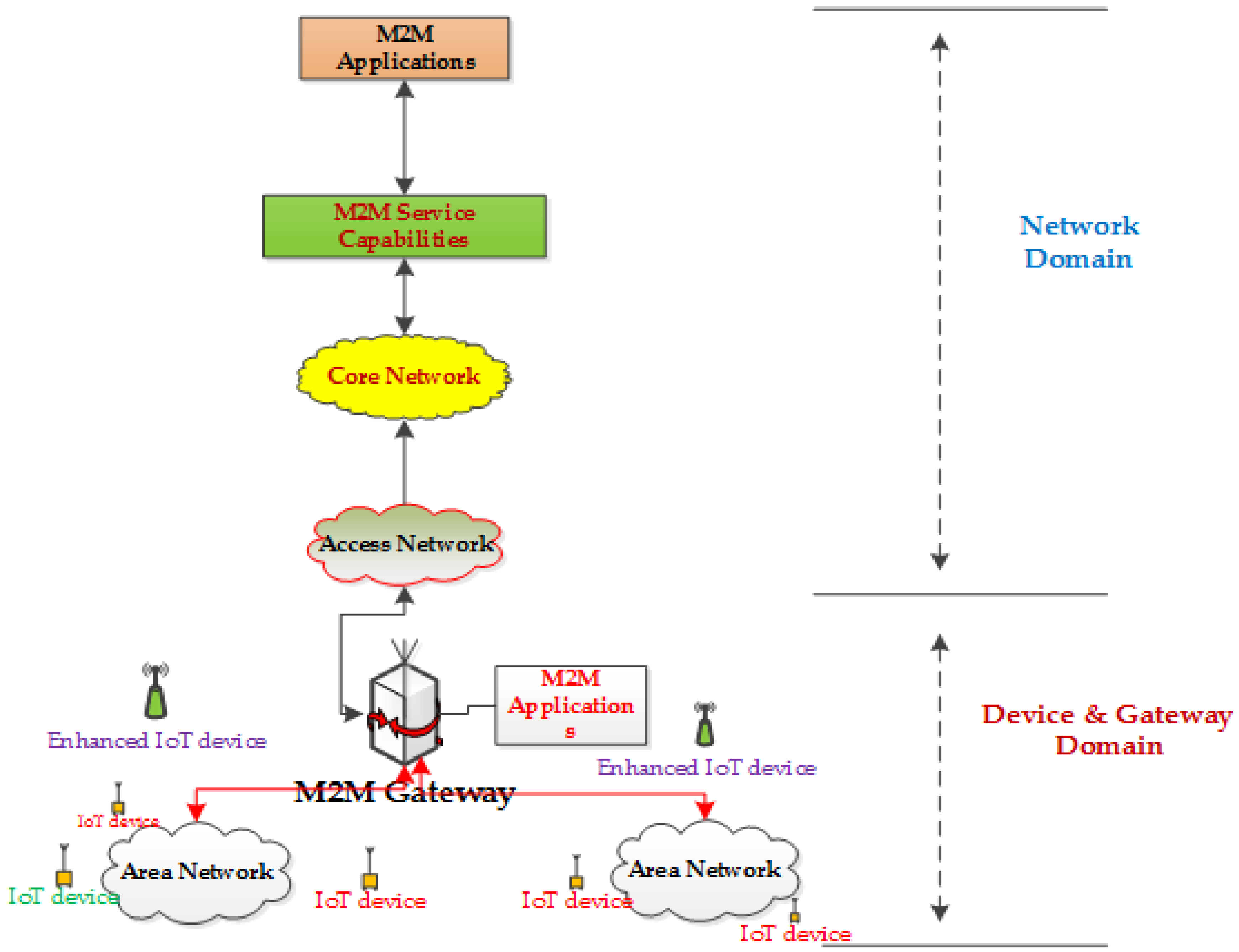
Figure 1 shows a functional M2M communication network architecture based on the ETSI standard [
5,
14]. The architecture is divided into two domains; the
device and gateway, and the
network. The device and gateway domain is composed of M2M devices, area networks, applications, and the M2M gateway. The network domain mainly consists of access and core networks, M2M management functions, and various M2M applications. The device and gateway domain can support two types of M2M devices where enhanced devices can have direct connectivity to application servers via the access network, whereas other devices with lower capabilities can only connect to the network domain via an M2M gateway through the area network as shown in the figure. M2M devices can also be connected to the network domain via multiple M2M gateways through different access networks. Network elements in the device and gateway domain should serve the M2M traffic directly from source nodes which are distributed over a wide area. These devices will generate short data bursts and have low energy consumption requirements. On the other hand, in the network domain, the data connections are mostly served by the gateways and enhanced M2M devices where data bursts are generally larger, with less restrictions on energy consumption. Connectivity in this domain can be supported by conventional cellular networking standards, as well as high data rate short range wireless networking standards. To support M2M communication requirements over a cellular network, new radio resource allocation techniques need to be developed so that short and infrequent data bursts can be efficiently served [
15,
16].
4. M2M Area Network Design
This section reviews the design requirements of M2M area networks using short-range wireless networking standards. M2M area networks will directly serve end devices which are spread over a geographical area. In order to collect data from distributed devices, it is necessary to provide seamless connectivity from devices to data servers. Direct connectivity from data devices to data servers will not be feasible due to the high density of nodes and transmission power requirements. It will be useful to relay data from devices via local gateways to the server using multi-hop links. Since end devices will generate infrequent data bursts, appropriate network topologies and MAC protocols need to be selected to offer seamless connectivity with maximum transmission efficiency at a minimum cost.
A low power wireless sensor network architecture is considered to be the most suitable for M2M area networks due to its lower cost and energy requirements. Wireless sensor networks generally use one of several network topologies for data transmission. The main network topologies used are: star, peer-to-peer, tree, and mesh [
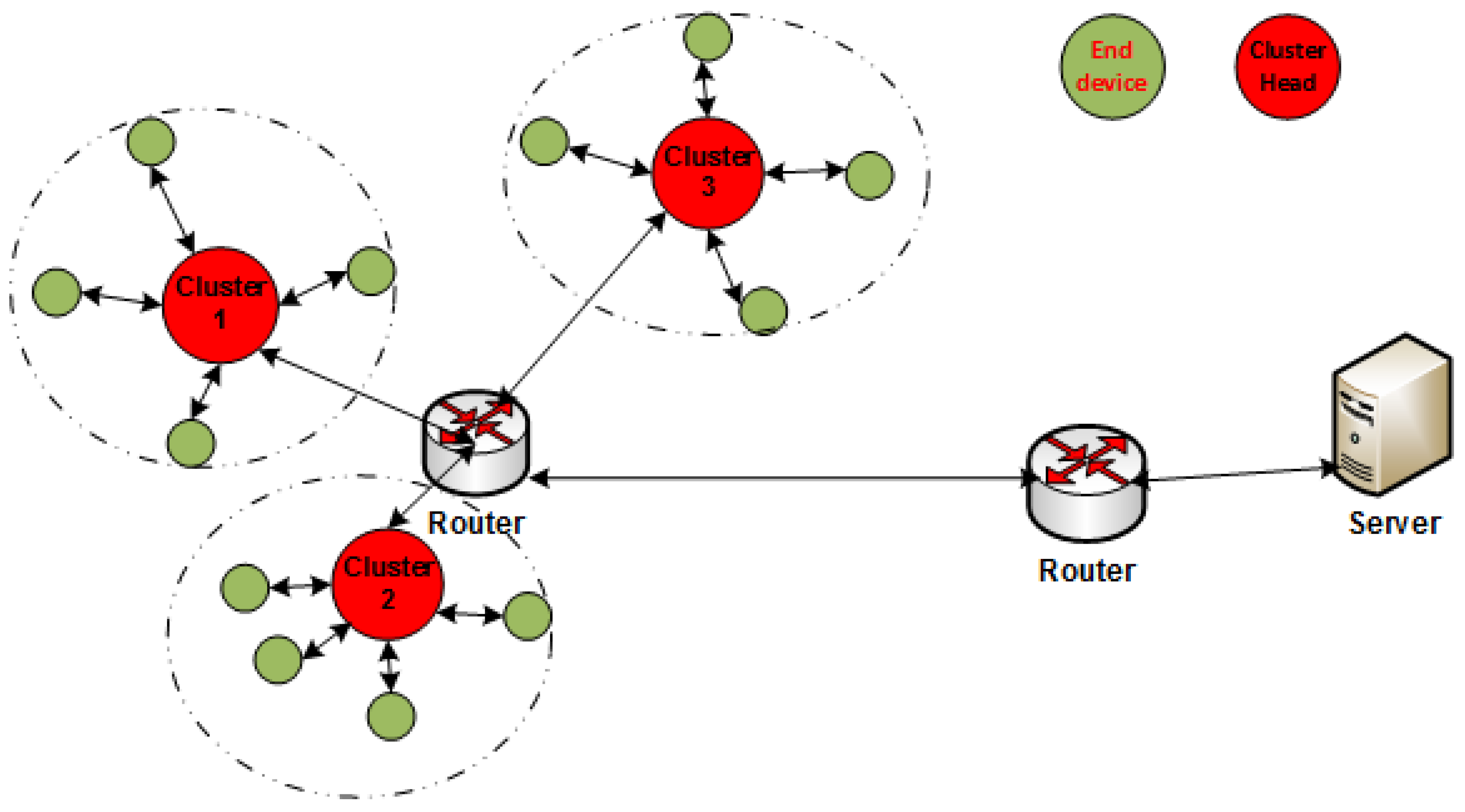
17]. The star topology is the most commonly used topology for small-size sensor networks, whereas the tree and mesh network architectures extend the communication range. The star topology uses a coordinator to exchange data among connected nodes; in wireless sensor networks the star topology is also referred to as the cluster topology where the coordinator becomes the cluster head. The transmission range of the cluster topology can be extended by using the cluster tree topology. In the cluster tree topology, multiple clusters communicate with each other either via cluster heads or routers as shown in
Figure 2. The cluster tree topology could be a suitable architecture for M2M area networks as the routers or gateways could be placed close to end devices reducing transmission power consumption and avoiding radio channel impairments.
The medium access control protocol is another critical design issue for M2M area networks [
18]. An M2M area network could be considered as a local and/or personal area network where one of three different classes of MAC protocols is used. These protocols are: scheduled access, random access, and polling [
17]. Scheduled access and polling protocols generally require more control signaling support compared to random access protocols and are generally not suitable for low-power area networks. High levels of signaling increases power consumption and computational complexities. On the other hand, random access protocols generally have lower signaling requirements at the expense of QoS degradation, particularly at high traffic load. Random access networks can maintain reasonable QoS as long as traffic load is low to moderate. Hence, it is necessary to develop advanced resource allocation techniques to maintain QoS in M2M networks.
In the last two decades, a number of short range wireless networking standards have emerged to support communications in local and personal area networking environments. Out of the many standards, several wireless networking standards have further progressed and become the potential candidates for M2M communication networks. In this section, we review the IEEE 802.15.4/6LoWPAN and IEEE 802.11 standards for M2M network infrastructure design in the device and gateway domain. There are other short range wireless standards, such as Bluetooth/IEEE 802.15.1, Wireless HART, LoRa, ECMA 368, and ISA 100.11a which could have roles in M2M network design, but considering the paper size we will limit our discussions to two main IEEE short-range wireless standards.
4.1. IEEE 802.11 MAC Standard
The IEEE 802.11 wireless local area network (WLAN) standard has been evolving over the last two decades. The 802.11 standard has been developed mainly to act as an access network using unlicensed spectrum in the 2.4 GHz and 5 GHz bands. The standard has evolved from a low data rate network to a gigabit network, supporting broadband connectivity.
Table 2 lists some of the key 802.11 standards with selected features. The table shows that revised versions of the standard have resulted in increased data rates over time. Very recently, the 802.11ah standard has been developed to support M2M and IoT communications using narrow band channels in a spectrum band below 1 GHz [
19]. This standard can support a large number of devices in outdoor environments, supporting sensor networking requirements. The IEEE 802.11p is another variant of the standard that has been developed for vehicular networks to support vehicular M2M communication systems.
For M2M communications, the 802.11 standard and in particular the 802.11ah variant, could play a key role, offering flexibility in designing and implementing M2M area networks. The standard operates based on the carrier sense multiple access with collision avoidance (CSMA/CA) protocol. The standard does not limit the number of stations that can associate in a network and, hence, is suitable for M2M communications. However, the actual number of stations in a network will be limited by the QoS requirements, since it is a contention/random access-based network. For M2M applications, it is necessary to use appropriate techniques to minimize the effect of contention in dense networking environments. Most of the 802.11 devices use physical carrier sensing techniques; however, virtual carrier sensing techniques could be more energy efficient.
The IEEE 802.11 standard specifies two different virtual carrier sensing mechanisms. The original virtual carrier sensing technique uses a network allocation vector (NAV) whereby network devices can overhear current transmissions to schedule their next channel sensing time to avoid collisions. A new virtual carrier sensing technique known as response indication deferral (RID) has been proposed for the IEEE 802.11ah standard. The difference between NAV and RID is that, in the case of RID, a collision-sensing flag is set immediately after the PHY layer header reception instead of after a full packet reception. In the case of RID, devices can resolve the collision status quickly to schedule transmission and sleeping periods in an efficient manner to reduce energy consumption, as well as to minimize contention levels in a network. It is worthwhile to mention that virtual carrier sensing is more energy efficient than physical carrier sensing techniques because, in the case of the former, a device does not need to sense the channel multiple times. As mentioned earlier, one of the key concerns of the CSMA/CA protocol is the lack of QoS support. The IEEE 802.11e standard introduced the enhanced distributed channel access (EDCA) technique to offer priorities to traffic classes as well as to offer QoS guarantees. However, the EDCA technique is not suitable for transmitting infrequent short bursts of traffic as seen in M2M and IoT applications. The emerging 802.11ah standard tries to address the contention problem in a dense networking environment by introducing a new technique known as restricted access window (RAW) that attempts to restrict contention levels by reducing channel access attempts over a longer period. The RAW technique divides network devices into groups and splits the transmission frame into slots. Contention levels within each time slot can be contained by restricting the number of terminals. The RAW technique can be seen as a combined TDM (Time Division Multiplex)/CSMA/CA channel structure. The technique needs to be further developed in order to optimize the RAW architecture so that the QoS of different applications can be supported. Other benefits of the emerging 802.11ah standard are: (i) short maximum header size of 28 bytes instead of 40 bytes, the MAC layer also supports a short six-byte header; (ii) supports a transmission range up to 1 km for a single hop link; and (iii) the suggested transmission power level is between less than 10 mW and 1 W depending on country regulations. The emerging standard has been designed targeting M2M networks; however, further research work needs to be carried out to optimize algorithms and network architecture.
4.2. IEEE 802.15.4 Standard
In recent times, the IEEE 802.15.4 network standard has received significant attention as a low power wireless sensor network and is the basis of Zigbee [
20]. The standard defines the physical and medium access control (MAC) layers for low-rate wireless personal area networks (LR-WPAN). The main advantages of the standard are reliable data transfer over short transmission distance, low energy requirements, as well as lower hardware and installation costs. The physical layer supports three different frequency bands: 2.45 GHz with 16 channels, 915 MHz with 10 channels, and 868 MHz with one channel. The data rate supported by the standard varies between 20 kbits/s to 250 kbits/s. A new extension of the standard known as 802.15.4g supports a data rate of 1 Mbits/s. The new physical layer also supports advanced functions such as channel selection, link quality estimation, channel energy detection and clear channel assessment (CCA). In the following paragraphs, the 802.15.4 MAC layer design will be discussed.
The MAC layer of the standard defines two types of node; reduced functionality device (RFD) and Full Functional Device (FFD). An FFD is enabled with a full set of MAC layer functionalities which allow this type of device to act as a network coordinator whereas an RFD device can only act as an end device, such as a sensor/actuator node. The standard can support both star/cluster and peer-to-peer topologies. The standard supports both beacon-based and non-beacon-based packet transmission techniques. This work only concentrates on the beacon-based packet transmission techniques.
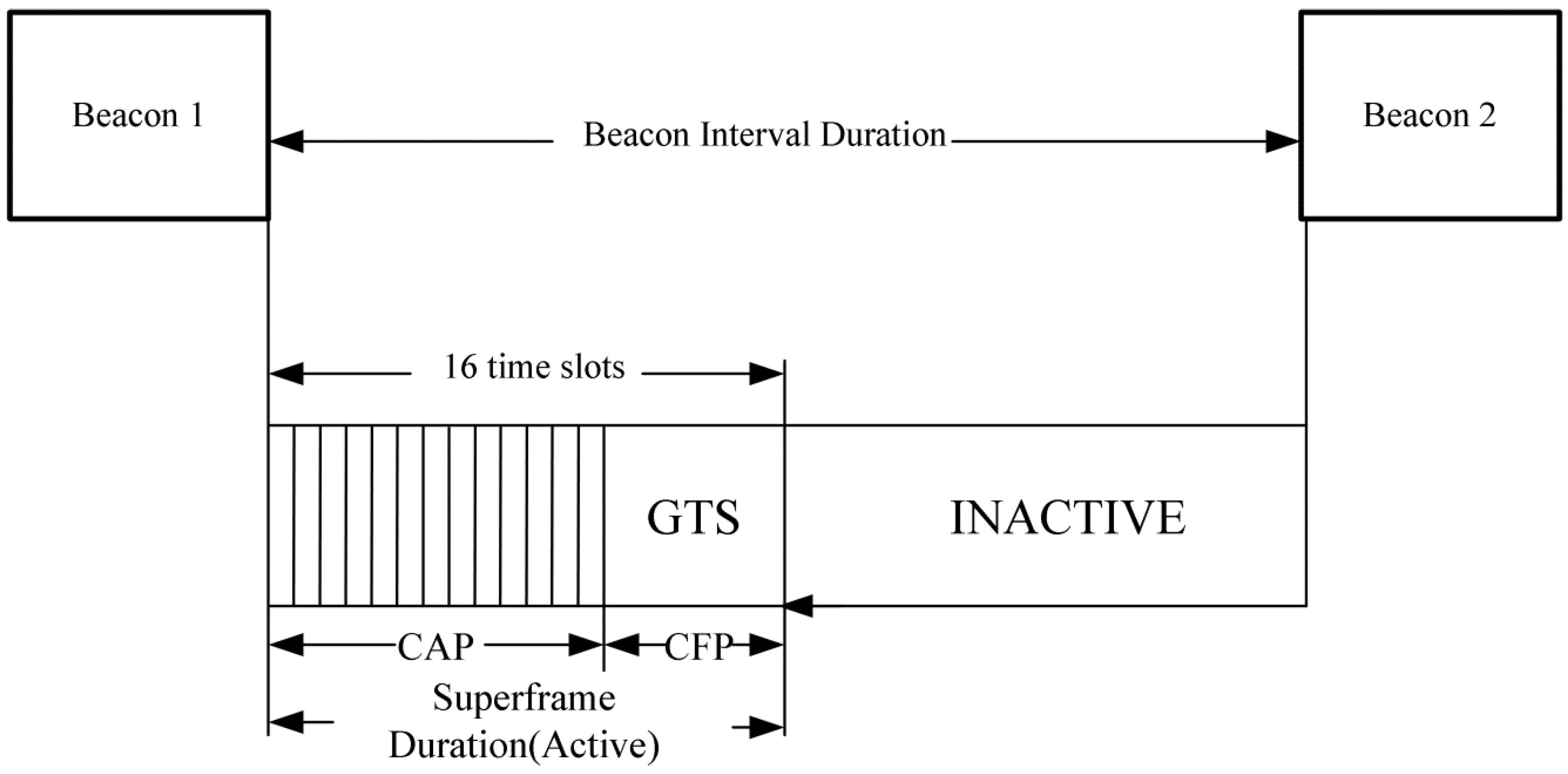
Figure 3 shows the superframe structure of the IEEE 802.15.4 standard. The frame starts with a beacon indicating the start of a transmission cycle. The beacons are separated by the beacon interval duration. The transmission interval is divided into two portions represented by active and inactive periods. The active period can be further divided into 16 time slots, which can be used by end devices to access the channel to transmit packets. The active period can be further categorized into the contention access period (CAP) and the contention free period (CFP). In the CAP period, end devices can transmit packets using the CSMA/CA mechanism. In the CFP part of the frame, fixed time slots are used which are referred as guaranteed time slots (GTSs). The GTSs are allocated in advance where devices can transmit their packets in a contention free mode. The CAP and CFP durations are adjustable depending on the application needs. The active period is followed by an inactive period when all end devices can remain in the sleep mode to conserve energy.
The super frame structure is controlled by two main parameters. Beacon Order (
BO) controls the duration between two beacon frames known as the Beacon Interval (
BI). Another parameter known as the Superframe Order (
SO) regulates the length of the CAP period. The beacon interval (
BI), superframe duration (
SD) and duty cycle (DC) are represented by Equations (1)–(3).
For the above equations, the following relation must hold 0 ≤ SO ≤ BO ≤ 14.
The IEEE 802.15.4 standard regulates the minimum superframe duration, which is equal to 960 symbols (15.36 ms). One time slot occupies 960/16 = 60 symbols (0.96 ms). Beacons contain control management information, such as the start and end of a superframe, address information, and the number of time slots allocated to the GTS service. If the CFP is disabled, then the entire active part of a super frame becomes the CAP duration. The CFP, in contrast, can allocate up to seven GTS slots that result in the minimum CAP length of 440 symbols, which is equal to eight time slots. This ensures sufficient time in which packets can be transmitted. Moreover, after a transmission, an acknowledgement for the received packet is sent back immediately to provide a reliable communication service by the MAC layer. A packet transmission has to be finished within one inter-frame spacing (IFS), otherwise the transmission will be deferred to the next superframe. The 6LoWPAN standard has been developed by the Internet Engineering Task Force (IETF) group by incorporating the IP (Internet Protocol) and associated layers on top of the IEEE 802.15.4 protocol stack [
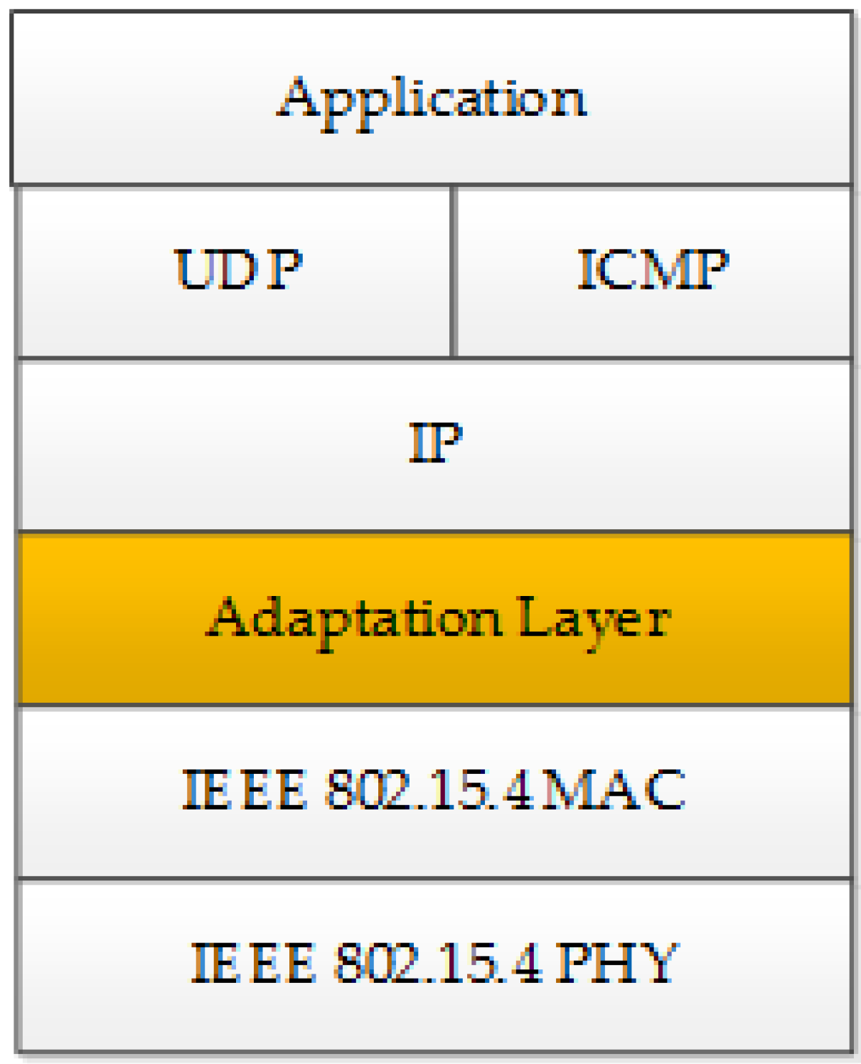
21]. The 6LoWPAN standard is capable of supporting both M2M and IoT applications.
Figure 4 shows the 6LoWPAN protocol stack. The adaptation layer is mainly used to compress 40 bytes IP header in to a two-byte field to be accommodated within a small size 128-byte 802.15.4 packet.
For an M2M area network, it is possible to use the 802.11/802.15.4 standards in a standalone mode. However, these standards have their own comparative limitations. The 802.11 standard’s main drawback is higher energy consumption compared to the IEEE 802.15.4 standard. The main advantages of the 802.11 standard are the increased data rate and a longer transmission range. The main relative advantage of the IEEE 802.15.4 is low power consumption. The main disadvantages of the 802.15.4 standard are low transmission data rate and a shorter transmission range. In this work, we propose a heterogeneous network architecture using both IEEE 802.11 and IEEE 802.15.4 standards to develop a high capacity, low-power, and long-range M2M area network exploiting the advantages of both standards.
5. M2M Heterogeneous Area Network
In this section, we present a heterogeneous M2M access network architecture based on IEEE 802.11 and IEEE 802.15.4 standards. The proposed heterogeneous network can support a large geographical area with deterministic QoS for M2M applications. One of the main problems of such a heterogeneous architecture is the overlap of the transmission spectrum in the 2.4 GHz band; particularly when operating in a dense networking environment. Spectrum overlap is referred to as the coexistence problem. The coexistence problem can generally arise when two or more co-located dissimilar networks share the same transmission spectrum with bands which are either partially or fully overlapped [
22]. To mitigate the coexistence problem, advanced channel management algorithms need to be developed. The IEEE 802.15.4 standard currently supports a number of operating spectrum bands; the main spectrum bands are the 2.4 GHz ISM (Industrial, Scientific, and Medical) band and the sub-GHz band between 700–900 MHz. The IEEE 802.11x currently uses the 2.4 GHz and 5 GHz bands for all current versions of the standard. The emerging IEEE 802.11ah standard will operate in the 900 MHz band. Hence, these network devices could generate inter-domain collisions (between 802.15.4/802.11 devices) since both standards are using the CSMA/CA protocol for packet transmissions. This work proposes a heterogeneous network architecture using 802.11 b/g and 802.15.4 standards to operate in the 2.4 GHz band that avoids the coexistence problem using a cooperative MAC protocol. For the smart grid and IoT applications, a lower transmission frequency will be more useful due to lower path loss which, in turn, could reduce transmission power and prolong the battery life.
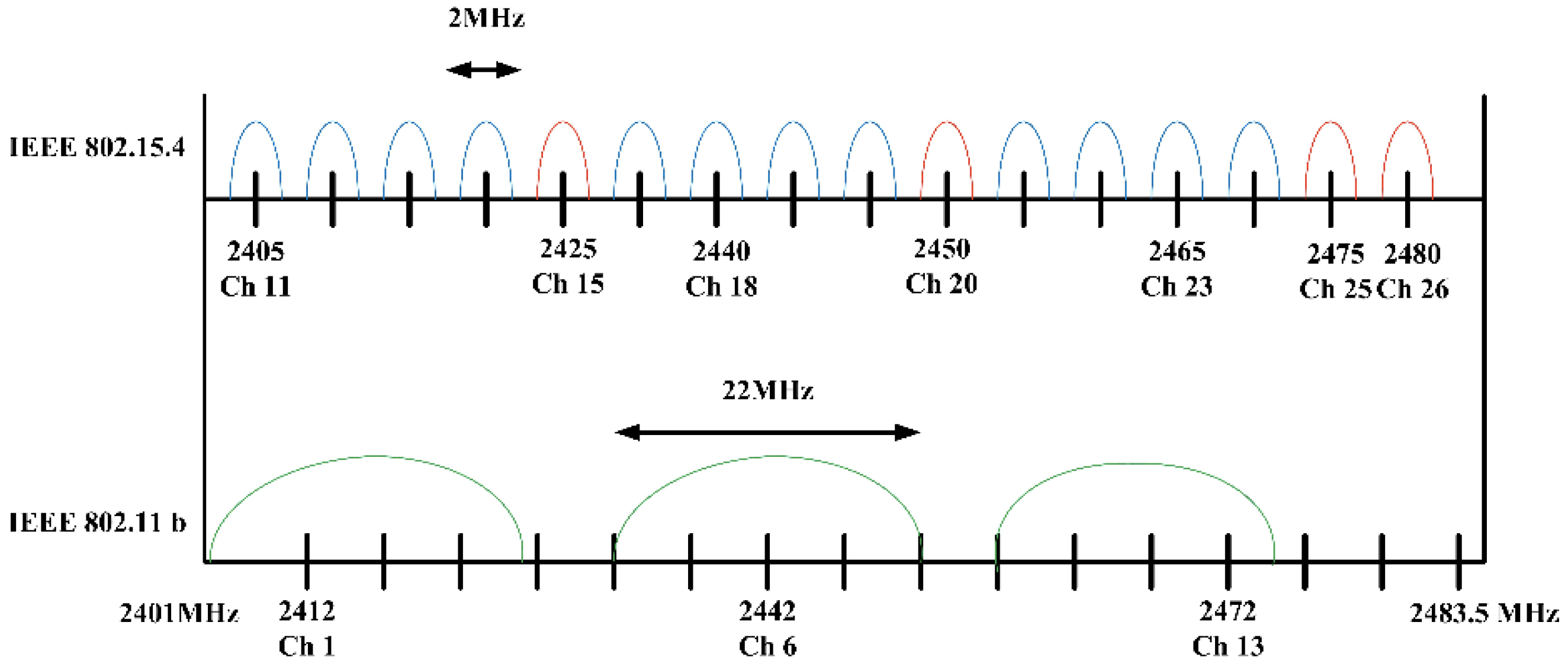
Figure 5 shows the operating spectra of the IEEE 802.15.4 and the IEEE 802.11b/g standards in the 2.4 GHz band. It can be seen from the figure that three IEEE 802.11b/g channels can generate interference for 12 out of 16 channels of the IEEE 802.15.4 standard. Additionally, the IEEE 802.11x channels are wider compared to the IEEE 802.15.4 channels. This overlap of transmission channels introduces a serious coexistence problem [
23,
24]. The IEEE 802.15.4 standard has the option of using a frequency hopping technique to avoid interference among network devices. Transceivers can select one of the sixteen transmission channels to avoid interference from co-located transmitters. However, such a solution may not be effective for a dense heterogeneous network environment where the number of co-located transceivers will be high, particularly considering the larger transmission range of 802.11 devices.
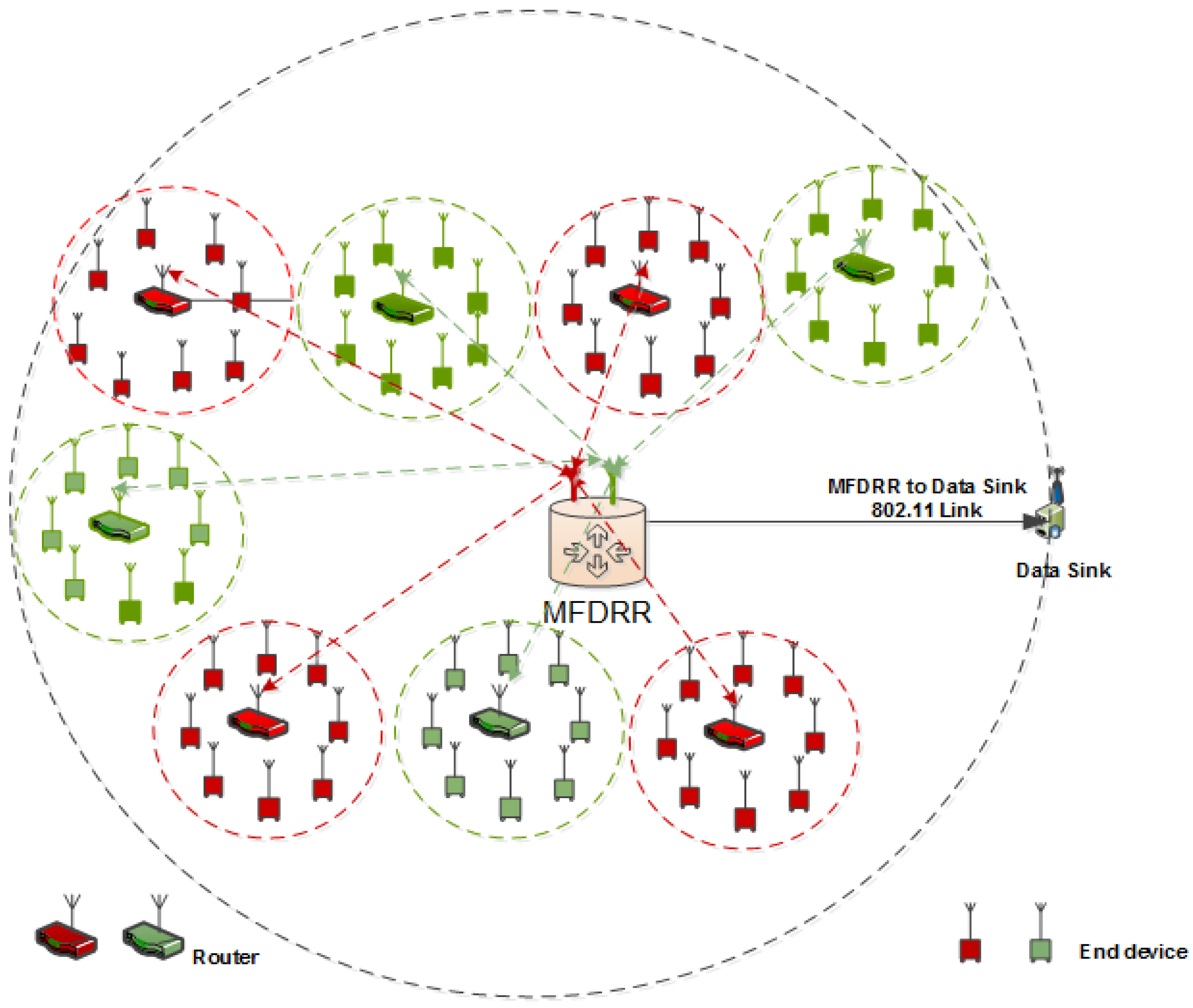
The proposed heterogeneous network architecture is shown in
Figure 6. The network is made up of
M sensor nodes divided into
N clusters where
P (P = M/N) is the number of nodes supported by each of the 6LoWPAN routers acting as the head of each cluster. The 6LoWPAN routers interface to a multi-frequency dual-radio router (MFDRR) gateway using 6LoWPAN interfaces. The MFDRR accepts data from the 6LoWPAN routers, aggregates data blocks, and transmits them to a data sink using an 802.11 link. This unique MFDRR architecture has been developed to avoid the coexistence problem. As the name suggests, the MFDRR can support multiple channels to accept data from different 802.15.4 clusters. In this network, different channels are used by neighboring clusters to avoid mutual cluster interferences. Hence, to accommodate dense networking environments, multiple 6LoWPAN radio interfaces are used at the MFDRR tuned to different carrier frequencies. In
Figure 6, red clusters use one carrier frequency while the green clusters use a non-overlapping different carrier frequency. As shown in the figure, the neighboring clusters will avoid interference due to use of alternating carrier frequencies. Additionally, the transmission power of end devices is limited such that packets can only be received by the local cluster heads. Hence, by using alternating carrier frequencies and limiting transmission power, inter-cluster interference can be avoided. The red and green dotted circles show the transmission distances of 802.15.4 end devices and the black dotted circles show the transmission distance of the 802.11 transmitter in the MFDRR. It can be easily seen that the 802.11 transmitter in the MFDRR will interfere with all 802.15.4 end devices while transmitting WLAN packets.
5.1. MFDRR Architecture
The most important and novel component of the proposed M2M area network is the MFDRR, which aggregates data and extends the transmission range, as well as increases the throughput of the heterogeneous network.
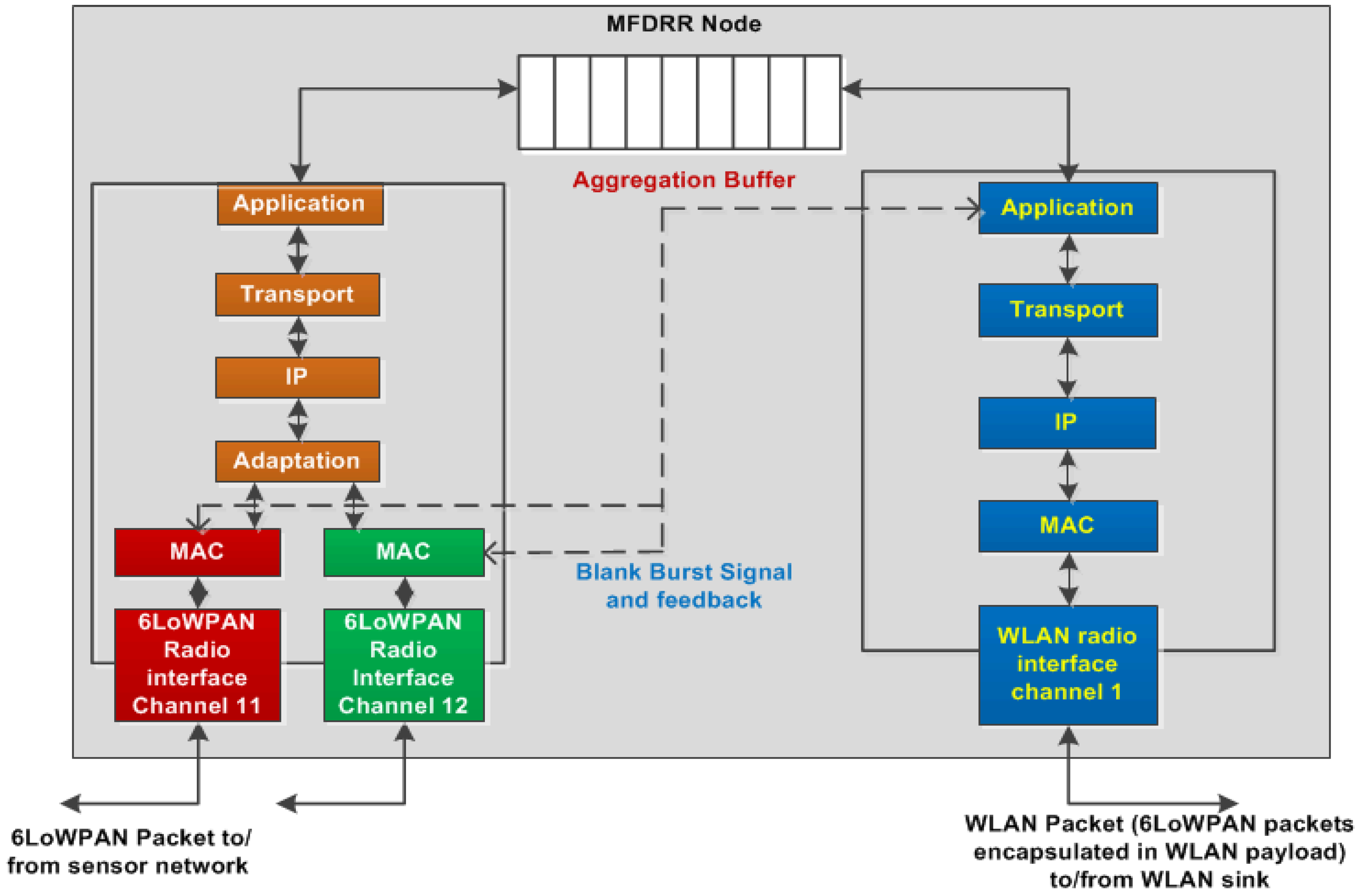
Figure 7 shows the MFDRR protocol stack and the queue structure. As can be seen from the figure, the MFDRR consists of two types of protocol stacks: the 6LoWPAN stack on the left side and the 802.11 stack on the right side. The former is developed in accordance with IEEE 802.15.4 and RFC 4944 standards [
25]. Two 6LoWPAN MAC layers and two physical interfaces are used to support two frequencies/channels as mentioned earlier. The 802.11 PHY and MAC layers are developed using the IEEE 802.11g standard [
26]. A buffer is used to connect the application layers of the two protocol stacks; the 6LoWPAN packets are stored in the buffer for the payload aggregation.
Data packet flow within the MFDRR is processed in the following manner: upon receiving an end device packet from a 6LoWPAN router, the MFDRR 6LoWPAN stack strips off its headers and hands over the payload to the application layer. Subsequently, the payload is stored in an aggregation buffer where payloads from multiple packets are aggregated to generate a WLAN payload for further transmission to the sink. Once the aggregation buffer length reaches a certain threshold value, the 802.11 application layer encapsulates multiple 6LoWPAN payloads and forwards the aggregated payload to the 802.11 MAC layer. The MAC layer then immediately generates a Blank Burst (BB) control signal to initiate an 802.11 packet transmission. The following section describes the BB signaling algorithm and 802.11 packet transmission technique.
5.2. The Blank Burst Algorithm
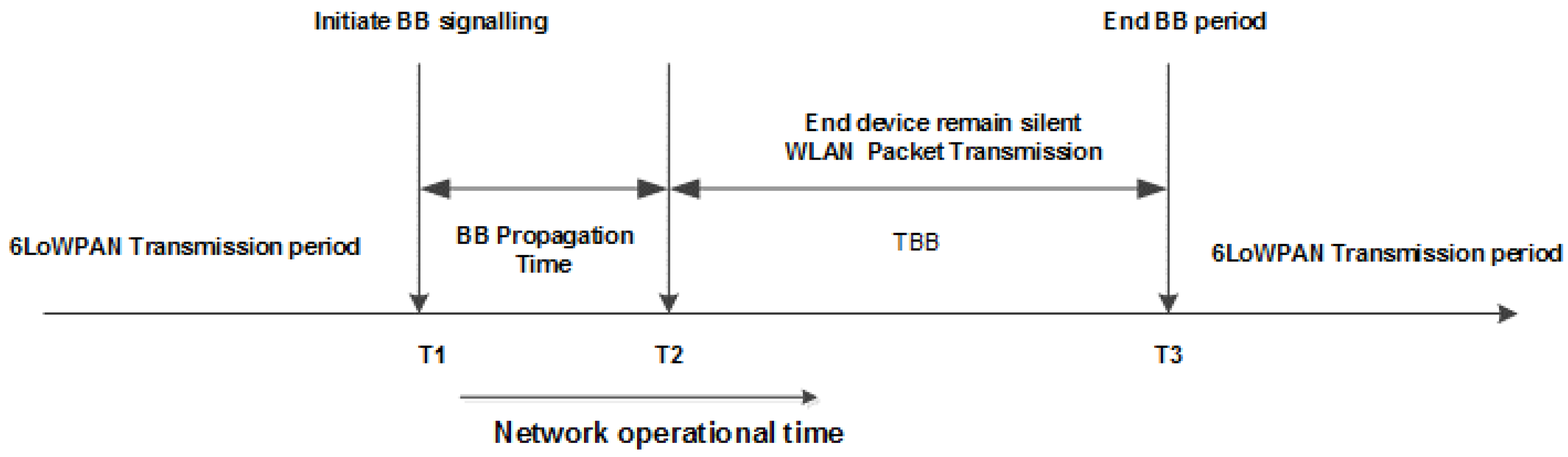
It is possible to transmit WLAN packets and 6LoWPAN packets simultaneously in the same area. However, a WLAN packet transmission can adversely affect 6LoWPAN packet transmissions owing to inter-network interference. To tackle this issue, we introduce a silence or blanking period that suspends the 6LoWPAN transmission during a WLAN packet transmission by using a cooperative MAC technique. The Blank Burst (BB) algorithm enforces a silence period on 802.15.4 devices and routers, thus, allowing the 802.11 transmitter to use the shared transmission channel in an interference free mode. In order to inform the end devices of this silence period, the 6LoWPAN superframe beacon is used where a BB signaling packet is inserted in the beacon field. We refer to this signaling mechanism as the Blank Burst (BB), which is generated and disseminated by the MFDRR. The BB packet transmission timing is shown in
Figure 8.
When 6LoWPAN payloads arrive at the MFDRR’s aggregation buffer, these payloads are aggregated into WLAN packets. Once the buffer length reaches a predefined threshold value, the BB control signal is triggered at time
T1 as shown in
Figure 8. A blank burst request is launched from the WLAN application layer which is relayed to the 6LoWPAN MAC layer as illustrated in
Figure 7. The length of the silence period
TBB is calculated using Equation (4), and included in the BB signal packet. At this point of time, the 6LoWPAN MAC layer sends a blank burst feedback signal to the WLAN application layer, indicating that the 6LoWPAN MAC layer is transmitting the BB signal to end users in the next superframe. The BB signal packet is transmitted from the MFDRR which is relayed by the 6LoWPAN routers to end devices. Upon receiving the BB signaling packet at time
T2, end devices move to sleep mode for the
TBB duration. Meanwhile, the 6LoWPAN packets are aggregated into WLAN packets in the MFDRR which, in turn, are transmitted to the data sink at time
T2. The 802.11 interface of the MFDRR uses the CSMA/CA protocol using the distributed coordination function (DCF) to transmit WLAN packets. In a single MFDRR-based network, the 802.11 packets will not experience any collision and, hence, they will be transmitted with a minimum delay. After the completion of this blank burst at time
T3, the end devices wake up and resume data packet transmission.
Equation (4) is used to calculate the blank burst duration where the DCF technique is used to transmit WLAN packets using the CSMA/CA protocol. In Equation (4) TDIFS denotes the distributed interframe spacing (DIFS); Tbackoff_min denotes the minimum back-off delay; Lagg denotes one WLAN packet transmission time including headers and payload, and TSIFS denotes short interframe spacing (SIFS). TACK represents the acknowledgement packet transmission delay. N denotes the number of WLAN packets transmitted per BB duration.
6. Simulation Model and Results
To evaluate the effectiveness of the proposed algorithm, a discrete event-based OPNET model has been developed to simulate the network architecture shown in
Figure 6. The key element of this model is the MFDRR that relays packets to and from end devices to the data sink.
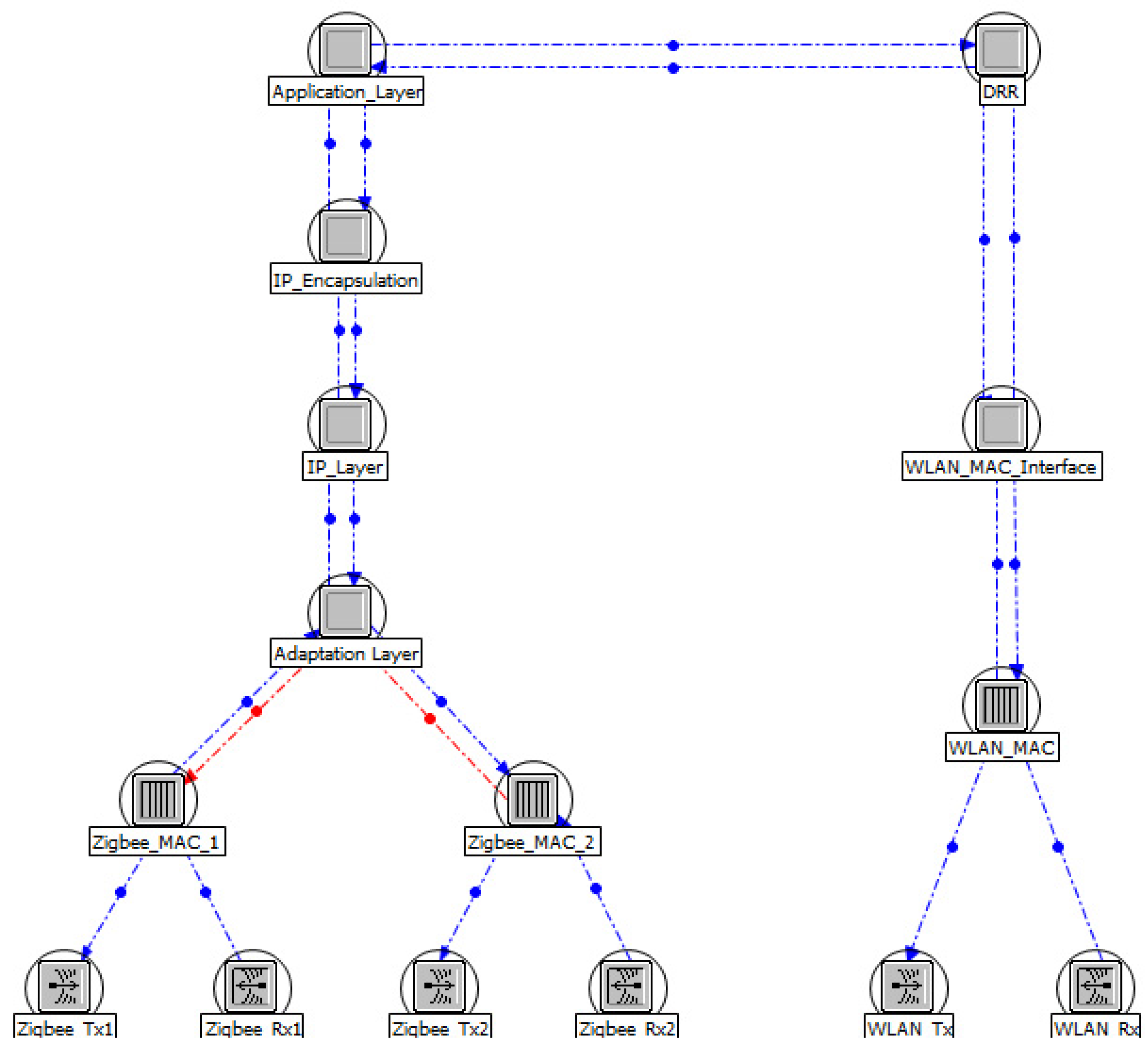
Figure 9 shows the OPNET model structure of the MFDRR. The left side of the figure shows the implementation of the 6LoWPAN protocol stack. Currently no 6LoWPAN model exists in the OPNET library, so we have developed a new 6LoWPAN OPNET model. The 6LoWPAN protocol stack has been developed utilizing the open-zb model available publicly [
27]. The open-zb model implements the PHY and MAC layers of the IEEE 802.15.4 slotted CSMA/CA protocol. The adaptation layer developed is responsible for the IPv6 header compression and de-compression as required by RFC 4944. The IP and application layers are implemented on top of the adaptation layer. The application layer of the MFDRR is split into two parts where the 6LoWPAN protocol forwards payloads to the aggregation buffer which is used to generate 802.11 packets. In the reverse direction, when a WLAN packet is received from the data sink, the 802.11 protocol stack strips all headers and delivers the combined payload to the 802.15.4 application layer. The combined payload is de-aggregated by the 6LoWPAN application layer and individual payloads are sequentially forwarded to the respective MAC layers for the downlink transmission. The 802.11 protocol stack was implemented using the OPNET library. The key simulation parameters are also listed in
Table 3. End devices are located 300 meters away from the coordinator. In the heterogeneous network, a three-hop transmission link is used, whereas six hops are used in the case of a comparative homogeneous network model when only 6LoWPAN nodes are employed. For the heterogeneous network, the MFDRR to the data sink uses a 6 Mbits/s link that significantly reduces the packet transmission time compensating for the packet aggregation delay introduced by the buffer.
Performance Analysis
This section evaluates the performance of the proposed M2M heterogeneous area network and the effectiveness of the proposed Blank Burst algorithm. Simulation results are used to compare the performance of two M2M area networks. Using simulation models, we evaluate the performance of the proposed algorithm by using the following metrics: packet success rate (PSR), end-to-end delay, and the number of collisions. The PSR is defined as the ratio of the number of packets successfully received by the data sink to the total number of packets generated by the end devices. The first two metrics are also used to compare the performance of homogeneous and heterogeneous M2M area networks.
Simulation models were used to obtain results from three different networking scenarios. In the first scenario, a homogeneous network is used where the network elements are 802.15.4 end devices, routers, and a data sink node. Thirty-two end devices are used using four 6LoWPAN clusters. A six-hop network is simulated that has the same end device to data sink transmission distance used in the heterogeneous network. In the second scenario, 64 end devices are used where a multi-frequency heterogeneous network architecture is simulated without implementing the BB signaling algorithm; this may result in inter-domain (802.11/802.15.4) collisions. In this case, once a 6LoWPAN payload arrives at the buffer, immediately a WLAN packet is generated and transmitted using the CSMA/CA protocol without the BB algorithm. In the third scenario, 6LoWPAN payloads are aggregated to generate a WLAN packet using a preset aggregation factor. Once a WLAN packet is generated, the BB signal is used to transmit the packet in an interference-free mode.
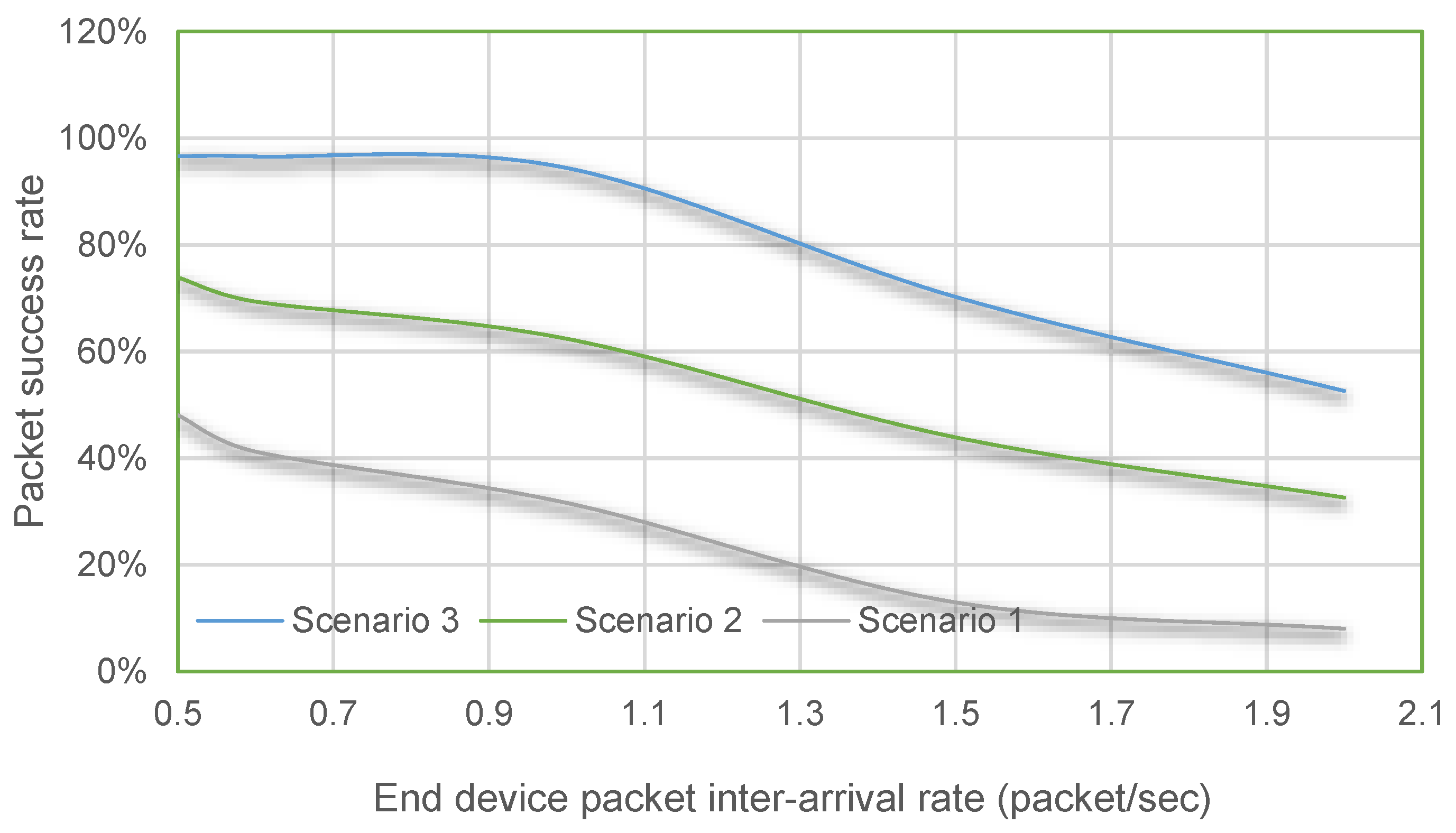
Figure 10 shows the packet success rate of the three networking scenarios and demonstrates the marked differences in PSR values among these three scenarios. The PSR of the heterogeneous network with the BB signaling (scenario 3) algorithm decreases gradually with the offered load; where the PSR drops from 97% to 53%. The PSR value of the heterogeneous network (scenario 2) without the BB algorithm drops from 75% to 30% with the increasing load. The homogeneous network (scenario 1) experiences the lowest PSR whose value reduces from 48% to 8%. The PSR value for these networks depends on the total number of collisions and network congestion levels.
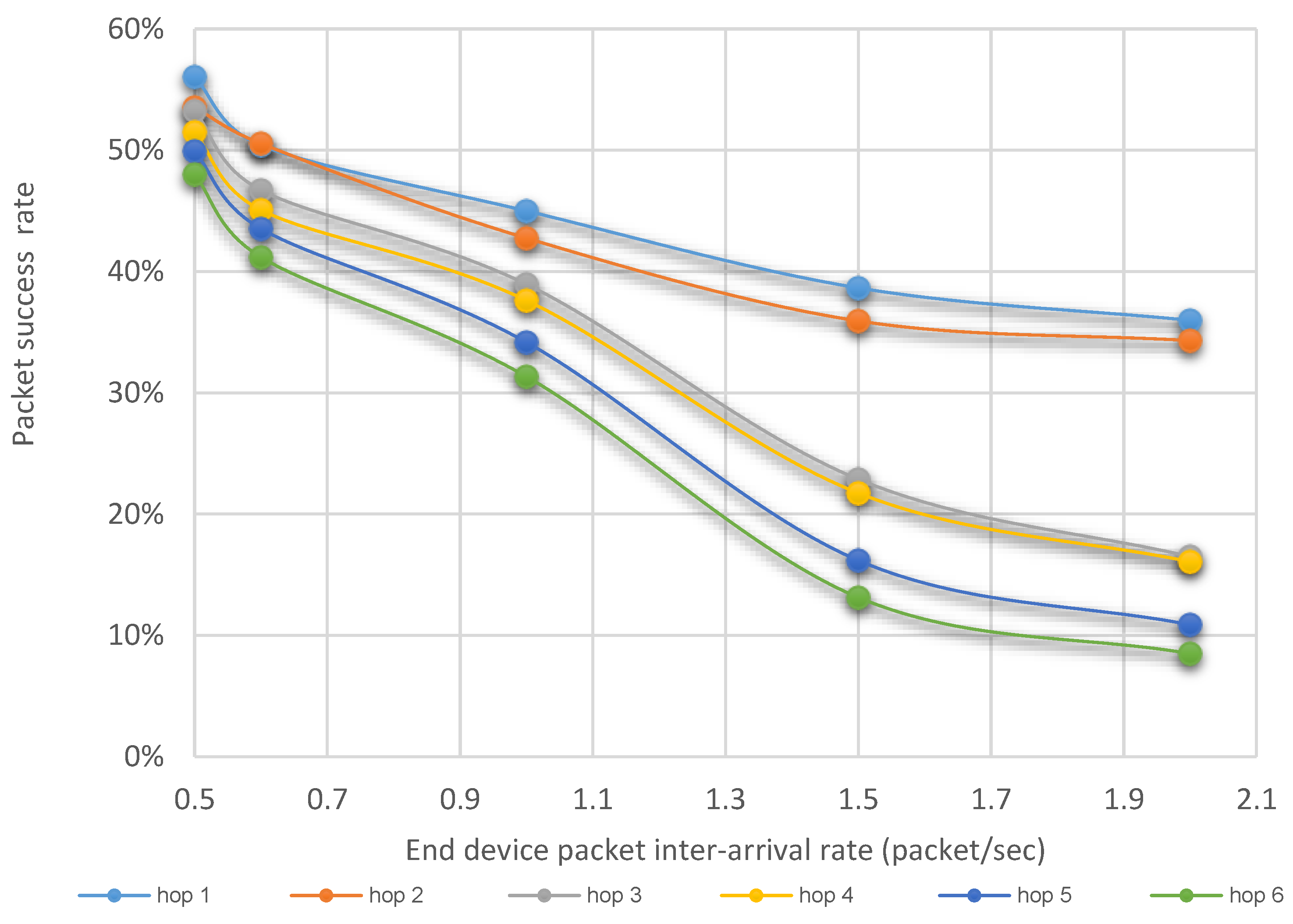
Figure 11 illustrates the link-by-link PSR rate of the homogeneous network. The plot shows that the PSR value progressively decreases from the end devices mainly due to collisions and network congestion. As more packets are accumulated in the routers, the network throughput decreases due to congestion and collisions. Although we have used a staggered link design to avoid collisions between neighboring 6LoWPAN clusters in the multi-hop network, the congestion level increases non-linearly with the load due to the use of the CSMA/CA protocol. For limiting the paper size we are not describing the staggered link design which can be found in [
28].
Comparing the PSR values of the heterogeneous network with and without the BB signaling algorithm shows that the BB signaling algorithm significantly increases the throughput. Improved performance is achieved due to the absence of inter-network collisions and lower network congestion. The heterogeneous network has the advantage of fewer hops, as well as a high data rate MFDRR to the data sink link. In this simulation, a 6 Mbits/s MFDRR to the data sink link was used.
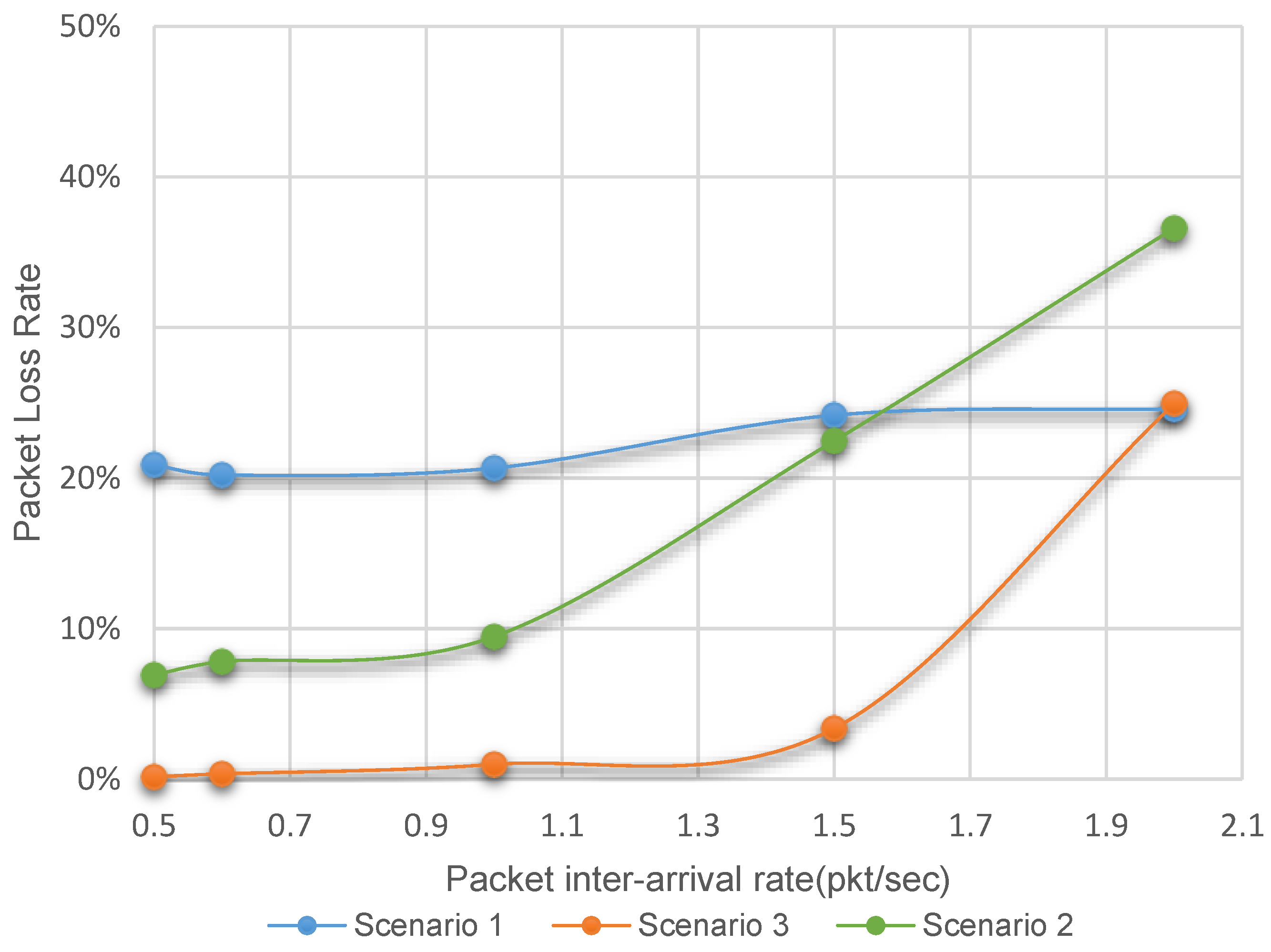
Figure 12 shows packet loss rates for all network simulation scenarios. Packets are dropped when the retransmission threshold is exceeded after multiple collisions; in this simulation, a retransmission threshold of four was used. For the homogeneous network, the packet drop rate is always high and remains steady due to lower network capacity and congestion; recall this scenario also experiences the lowest PSR. The plot shows the significant improvement of the heterogeneous network performance when the BB signaling is used. As shown in the figure for scenario 3 with traffic load up to 1.5 packets/s/node, the overall packet loss rate remains very low. Compared to scenario 3, scenario 2 results in a much higher packet loss rate even at low network traffic loads. In the heterogeneous network when BB signaling is not used, then both intra and inter network collisions increase due to the mutual interference between data packets as well as interference between data and ACK packets. Results clearly show that packet loss rate increases exponentially with incoming traffic without the BB signaling. The proposed signaling mechanism offers significant QoS gain by using the cooperative MAC protocol, which allows the sharing of the transmission channel in a fair non-collision mode. In heterogeneous networks, one must consider the transmission ranges of the two different networks. The 802.11 transmitter covers a longer transmission range, as well as transmits at a higher transmission power, compared to 802.15.4 devices. Hence, any 802.11 packet could collide with a large number of end device packets when an omnidirectional antenna is used in the MFDRR. Use of the uniquely-proposed BB signaling completely eliminates the inter-network collisions.
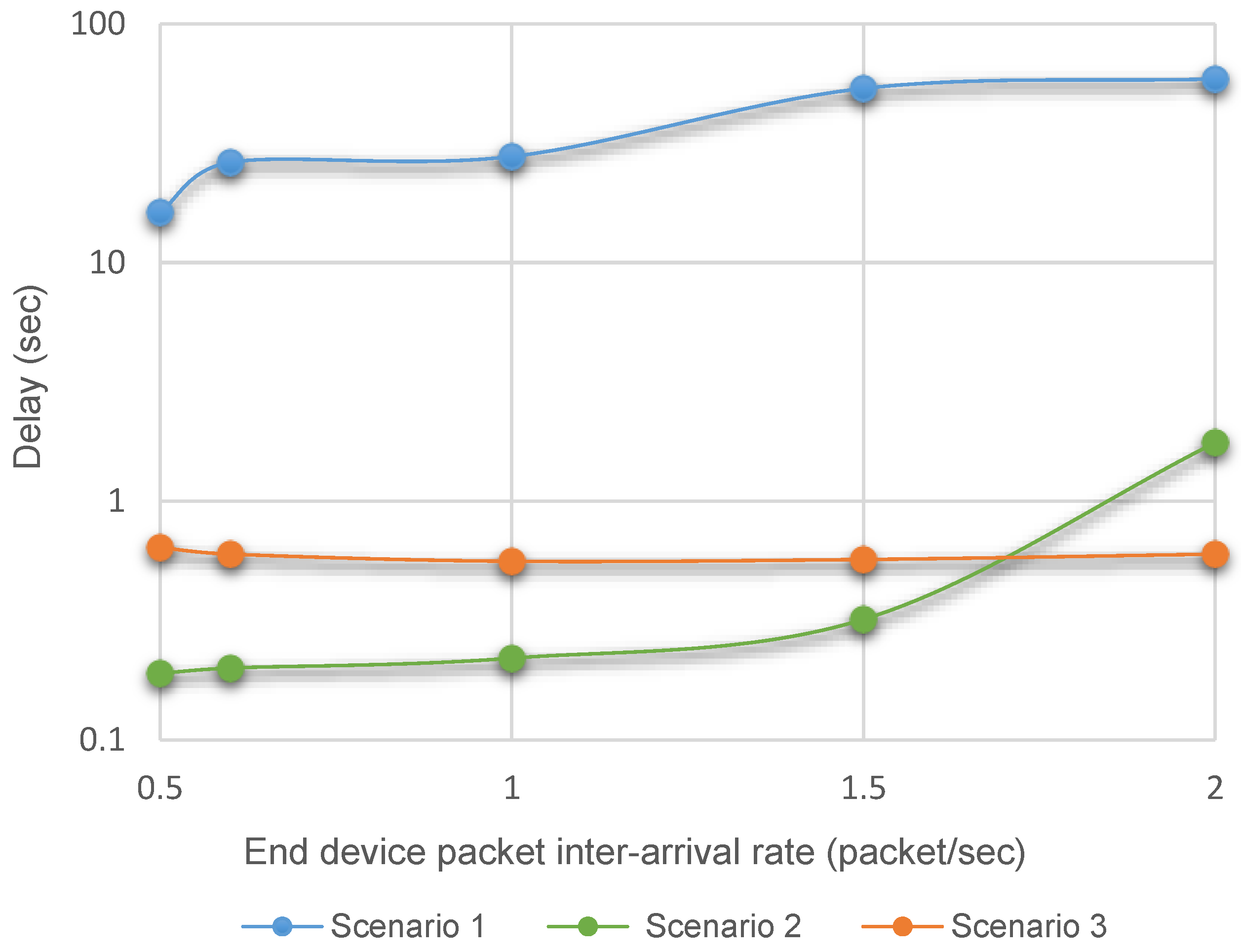
End-to-end delay plays a significant role in evaluating network performance.
Figure 13 shows the end-to-end packet delay for the three simulation scenarios. The plot shows that the homogeneous network introduces very high packet delay due to the higher number of collisions and network congestion in a multi-hop network. Simulation results show that the largest component of the delay is the queuing delay at the router due to the congestion. Comparing the delay of the heterogeneous network, it can be seen that the heterogeneous network without the packet aggregation and the BB signaling offers a lower delay at a low offered load, but the delay increases significantly as the load increases. One of the reasons for the lower delay is the shorter queuing delay because packet aggregation is not used. However, this advantage diminishes as the load increases due to high collision rates. On the other hand, the network with BB signaling maintains a stable end-to-end delay for all load conditions. At low traffic load, the delay is higher compared to scenario 2 due to the longer wait period caused by the BB signal propagation delay. Over the multihop network, the MFDRR needs to wait several superframe periods to allow the BB packets to propagate to all end devices. On the other hand, at higher load, the scenario 3 delay is lower compared to scenario 2 due to absence of interdomain collisions. The end-to-end packet delay for an
N hop network using the proposed heterogeneous network can be expressed by Equation (5) where
Ta,i is the link access delay,
TQ is the queuing delay at the router,
Tagg is the packet aggregation delay at the MFDRR, and
TBB is the blank burst delay which absorbs the WLAN packet transmission time. A higher packet arrival rate could increase the total access delay in the 6LoWPAN clusters, but this delay is compensated for by the lower aggregation delay. Additionally, the BB signaling technique completely eliminates the inter-domain collisions; hence, performance at higher load is not affected by the co-existence issue.
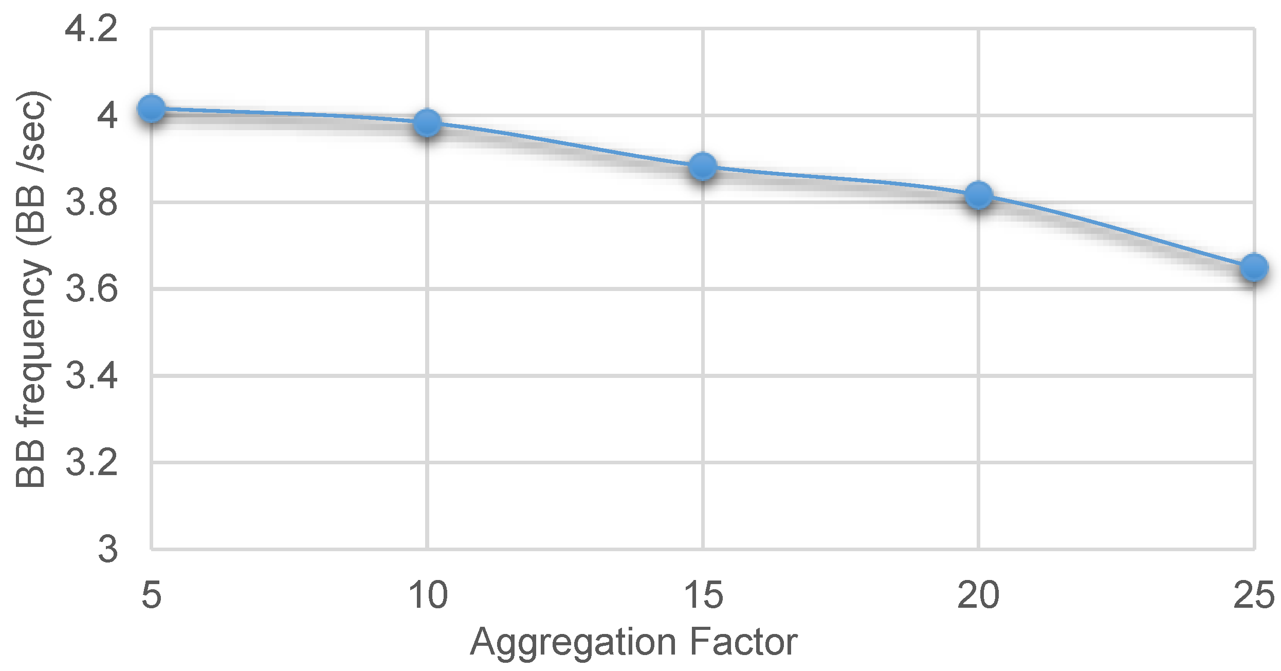
Figure 14 shows the BB signaling frequency for different aggregation factors at the highest considered network traffic load. The results show that end devices are enforced into the sleep state between 3.6 times/s and 4 times/s when devices cannot transmit any packets. In this simulation, a 2.7 ms BB duration is used. In this case, end devices remain silent for a maximum of 10.8 ms/s. Use of silent periods does not affect the cluster throughput for two reasons: first, the silent period is very small, a maximum of 10.8 ms/s; secondly, due to the staggered link design, some of the silent duration will overlap with the sleep period of superframes of different links. From simulation results, it was found that the average cluster throughput is 12.4 packets/s and 12.3 packets/s for the no BB and the BB scenarios respectively. Results indicate that the BB signaling improves the overall network throughput and QoS by reducing inter-domain collisions, whereas cluster throughputs from end devices are not affected by the signaling technique.
7. Conclusions
This paper has presented a new cooperative MAC protocol for an M2M heterogeneous area network to support IoT applications using low-cost wireless networking standards that operate in the unlicensed spectrum. The work specifically focused on eliminating the inter-network collision problem to improve the throughput of an M2M area network in a dense networking environment. Simulation results show that the proposed blank burst signaling algorithm reduces the number of inter-network collisions significantly and maintains a stable delay profile. The BB signaling structure has no negative impact on the access network’s delay due to the introduction of silence periods. The BB signaling architecture improves the PSR value, as well as offers a stable delay and makes the end-to-end delay less dependent on the traffic load. The BB signaling design can accommodate different traffic QoS requirements by adjusting the BB signaling period. The proposed signaling structure requires no additional signaling traffic since the BB signal is propagated by using the beacon field of the superframe. The design presented here is also scalable where both networks can share the common transmission spectrum without intra- and inter-network collisions. The proposed network architecture is suitable for a dense network deployment where the frequency hopping technique may not be useful to avoid inter-network collisions or interference. The proposed solution is also energy efficient compared to 3G/4G cellular networks since the short range networking standards use lower transmission power, as well as have lower signaling load. The developed BB signaling does not require any additional transmission resources as the BB signal is mapped onto the existing IEEE 802.15.4 superframes; hence, no additional transmission energy is necessary. It is well known that IEEE 802.15.4 networks are far more energy efficient than 4G/LTE networks [
29]. The proposed heterogeneous network will maintain the same level of energy efficiency while providing M2M area networking support over a wide area. Other works have shown that cooperative MAC protocols in a random access network can improve the energy efficiency. [
30] proposed a distributed information sharing (DISH) cooperative approach for a multichannel MAC to improve the energy efficiency.
The proposed network will be further extended to incorporate multiple MFDRRs to support increased node density in a geographical area. Future research will also concentrate on the heterogeneous network architecture using the IEEE 802.11ah standard.


