Article

A Novel Map-Based Dead-Reckoning Algorithm for Indoor Localization

1
Interactive and Digital Media Institute, National University of Singapore, Singapore 119077, Singapore
2
NUS Graduate School for Integrative Science and Engineering, National University of Singapore, Singapore 119077, Singapore
3
Department of Electrical & Computer Engineering, National University of Singapore, Singapore 119077, Singapore
*
Author to whom correspondence should be addressed.
J. Sens. Actuator Netw. 2014, 3(1), 44-63; https://doi.org/10.3390/jsan3010044
Submission received: 26 November 2013 / Revised: 15 December 2013 / Accepted: 23 December 2013 / Published: 3 January 2014

Abstract

:
Step counting-based dead-reckoning has been widely accepted as a cheap and effective solution for indoor pedestrian tracking using a hand-held device equipped with motion sensors. To compensate for the accumulating error in a dead-reckoning tracking system, extra techniques are always fused together to form a hybrid system. In this paper, we first propose a map matching (MM) enhanced particle filter (PF) as a robust localization solution, in which MM utilizes the corridor information to calibrate the step direction estimation and PF is applied to filter out impossible locations. To overcome the dependency on manually input corridor information in the MM algorithm, as well as the computational complexity in combining two such algorithms, an improved PF is proposed. By better modelling of the location error, the improved PF calibrates the location estimation, as well as step direction estimation when the map information is available, while keeping the computational complexity the same as the original PF. Experimental results show that in a quite dense map constraint environment with corridors, the proposed methods have similar accuracy, but outperform the original PF in terms of accuracy. When only partial map constraints are applied to simulate a new testbed, the improved PF obtains the most robust and accurate results. Therefore, the improved PF is the recommended DR solution, which is adaptive to various indoor environments.

1. Introduction

Location awareness is the basic requirement for developing new exciting location-based services (LBS). Compared to common applications supported by outdoor positioning techniques, like the Global Position System (GPS), it is extremely challenging to provide similar ubiquitous and affordable services in indoor environments. Unlike GPS, providing almost full coverage for the whole Earth’s surface, indoor localization provides a solution in a quite smaller scale. The cellular base station-based indoor localization technique [1] provides almost the largest coverage among indoor localization techniques, which sacrifices the accuracy of the solution. To provide a more reliable solution, additional indoor infrastructure deployment is always necessary. Because of the great complexity of the indoor environments, the applied techniques can be quite different.
The most favored indoor technology has been WiFi access points, which is because of their comparable large coverage, and yet, they provide a satisfying solution in certain circumstances [2]. If higher accuracy is demanded, researchers have preferred technologies, like ultrasound and Bluetooth [3,4]. One of the drawbacks is that they have smaller coverage, and scaling up will incur a high deployment cost. Besides, they are not as common as WiFi in indoor environments.
The infrastructure-based techniques can be categorized into two types, namely training algorithms and non-training algorithms. The training algorithms work based on the assumption that the received signals are different in various locations. The first step is to collect the signal patterns in different ground truths. The signals undergo off-line processing to obtain a reference database. A received real-time signal on the receiver is then compared with those in the database, and the best match location is returned. Non-training techniques always rely on distance estimation. In a dense deployment scenario, a multilateration technique can be applied. Given the same deployment, the training algorithms always return more accurate results compared to the non-training algorithms. However, the training algorithms are vulnerable to environment changes, and the training is labor intensive.
To decrease the cost of deployment, dead-reckoning (DR) techniques relying on inertial measurement unit (IMU) sensors have been proposed [5,6], which have always been applied in GPS systems to improve the robustness of the results. An IMU sensor is able to track its movement by the equipped accelerometers, gyroscopes and magnetometers. The DR method derives the current location by adding the estimated displacement to the previous estimated location. Suppose no external information except the initial location is known; the performance of DR totally relies on the measurement accuracy of the sensors. It is intuitive to find that the DR methods suffer from accumulating errors in the measurements.
Although additional indoor infrastructure is still necessary in order to provide the initial location estimate and performs as the calibration reference, the DR method reduces the demand on the density of the deployment. The DR method provides quite accurate displacement estimation within a short path. The placement of the sensor results in different strategies to calculate the displacement. An intuitive computation method is to double integrate the accelerations in the global coordinate. The fast increasing error is compensated for by a method called zero velocity update (ZUPT) [7,8,9,10]. The fact that a foot on the ground has zero speed is quite useful. However, unless it is in a controlled scenario, wearing the sensor on the foot is quite inconvenient.
The recent development of motion sensors in smart phones has made the DR algorithm for general pedestrians possible. Considering the tremendous demand from pedestrians, it is worth providing a localization solution in the scenarios when a smart phone is used. Step counting is a well-known algorithm to estimate the displacement when the sensors are not placed on the foot. From the readings of acceleration, it is able to tell if a pedestrian has walked a step. The step displacement is estimated after each step, which is then added to the previous location estimate. That is why it is called step counting. A step counting algorithm is constituted by step detection, step length estimation and step direction estimation. Step length estimation generally returns satisfactory results, and it can be further improved by a simple training process.
Step direction estimation is the most challenging component, as it is sensitive to error in the sensor’s orientation estimation. In order to accurately determine the sensor’s orientation, the known direction of the Earth’s gravity and the magnetic field are required. Let the global coordinate be east-north-up (E-N-U), which coincides with the sensor’s x-y-z coordinate, initially. The rotation of the sensor is decomposed as rotations about its axes at the sequence of its z-y-x axis by angle ψ-θ-ϕ, respectively. The direction of the Earth’s gravity determines θ and ϕ, which can resolve the vertical and horizontal components of acceleration, given that θ and ϕ, ψ can be resolved from the known magnetic field. The quasi-uniqueness of gravity provides a robust solution for θ and ϕ, which, in turn, facilitates reliable step detection and step length estimation. However, the studies in [11,12] have indicated that there are considerable random disturbances of the magnetic field in an indoor environment, which makes the estimation of ψ unreliable, and hence, the estimation of step direction is affected. Although the orientation can be solved by angular rate integration, the error accumulates if the direction of the magnetic field is not used for calibration.
In this paper, we focus on dealing with the error in direction estimation, which is helped by incorporating the indoor map information. In this paper, we first propose a new step counting algorithm with the map matching (MM) method. It is based on the observation that the pedestrian tends to walk along a quasi-straight line when he is in a corridor. Once this walk pattern is detected and there is a nearby corridor, the estimated location is mapped to the corridor, and the step direction and the sensor’s orientation is calibrated by the known corridor’s direction. The drawback of the MM algorithm is that the required narrow corridors are not always available in an indoor environment. To compensate for such a drawback, we also propose a hybrid solution. The map matching algorithm is applied as a supplementary algorithm of the particle filter (PF), which is called the MM-enabled PF, to form a more robust solution. In the end, we propose an improved PF, which simulates the uncertainty in the step direction estimation. The particles with the wrong location estimation are more likely to be the ones with the wrong direction estimation, which would be eliminated by map constraints. The improved PF returns a more robust result, with less computational complexity compared to the MM-enabled PF.
The sensor we use is ADIS16405BMLZ [13], containing a three-axis accelerometer, a three-axis gyroscope and a three-axis magnetometer. To simulate the usage of a smart phone, the sensor is put in a trouser pocket, as shown in Figure 1 for data collection during walking, as many people carry their phones in their trouser pockets [14].
Figure 1. The sensor we used and the setting for data collection.
Jsan 03 00044 g001
In order to perform the experimental study, our laboratory was chosen as the indoor tracking testbed. The layout is shown in Figure 2. The size of the testbed is about 22 m by 18 m. The coordinate system and the coordinates for some locations are also indicated. The map contains obstacles, walls and accessible areas. There are three corridors available in total in this map for the MM algorithm. Later, the map will be represented as simple lines and rectangles.
Figure 2. Experimental testbed with walls and obstacles.
Jsan 03 00044 g002
The rest of the paper is organized as follows. Section 2 describes the related works regarding step counting-based DR algorithms. In Section 3, the major components for the step counting algorithm are reviewed, which is also the basis of our proposed approach. In Section 4, the particle filtering algorithm and our proposed map matching algorithm are illustrated, as well as the hybrid method. An improved PF is proposed in Section 5 for robust performance without the requirement of corridor information. Experimental studies are given in Section 6 for performance comparison. Finally, we conclude in Section 7.

2. Related Work

DR algorithms have been widely applied in indoor localization, as in [5,9,15,16], etc. Considering the in-pocket tracking scenario, the step counting algorithm [17,18,19,20] is the preferred DR algorithm. The step counting algorithm is made up of step detection, step length estimation and step direction estimation. A step is detected by a pair of a peak and a valley of the one-axis accelerations in the global coordinate meeting some requirements. A claimed to be more robust way is to look at the peaks and valleys of the modulus of the three-axis accelerations [21]. Step length is related to the vertical component and the modulus of the horizontal component in the global coordinate. Step direction is determined by the horizontal component of acceleration in the global coordinate if we only consider two-dimensional (2D) movement.
The motion sensor we use comprises a three-axis accelerometer, a three-axis gyroscope and a three-axis magnetometer. If the initial orientation is known, the subsequent orientation is updated by the angular rate returned by the gyroscope. The Earth’s magnetic field and gravity can be used to obtain the initial orientation and to compensate for the accumulating errors of orientation from the gyroscope. In an ideal environment with identical magnetic field and gravity, the sensor’s orientation could be accurately determined.
It is obvious that the fundamental requirement is to compute the sensor’s orientation accurately, so that the acceleration in the sensor coordinate can be accurately resolved to the global coordinate. However, because of severe magnetic interference in an indoor environment, that is not an easy task. Several attempts have been made to eliminate the effect of magnetic disturbance, like the work in [22,23,24]. However, the algorithms work under the assumption that the disturbance comes from a single source, and the evaluation is taken in controlled environments. The sources of indoor magnetic disturbance are much more complex than that.
To improve the DR tracking results, map information has been widely used, as the map information is available to landowners. Map filtering is applied to eliminate impossible particles, like walking through a wall or an obstacle, which is quite effective in an indoor environment with lots of walls and obstacles. References [25,26,27] are examples of applying PF-based map filtering in indoor tracking. The uncertainty in location estimation is represented as particles with different locations. While the locations of the particles are updated by the step measurement, particles with an inaccessible path are eliminated and new particles are generated. Improvement has been made in [10] by a so-called backtracking particle filter (BPF). BPF takes advantage of long-range geometrical constraint information that the estimated path is always backtracked, so that the particles proven to be unsuitable are eliminated in previous steps. In this way, the localization results of the previous steps are improved.
The existing algorithms only use map information to distinguish accessible and inaccessible areas. More improvement can be achieved by applying MM. MM has been applied for outdoor environments in road tracking [28,29]. In our previous work [30], the tracked path is mapped to a nearby known corridor if certain requirements are met. Through map matching, the sensor’s location, orientation, as well as the pedestrian’s walking direction can be rectified. The improvement in the sensor’s orientation and step direction estimation reduces the error in future tracking. The drawback of a pure map matching algorithm is that it does not make full use of the map constraints, but only the corridors. In this paper, we apply map matching as a supplementary algorithm to the original PF method, which gives more robust results. Another contribution of this paper is the improvement of the original PF. In the literature, the error in step counting localization is simply defined as additive arbitrary Gaussian noise in location estimation, which does not simulate the error well. The error should be decomposed as error in step length estimation and another in step direction estimation, which have different attitudes. By defining a more accurate system model, our particle filter performs better than previous ones given the same map constraint information.

3. Step Counting Dead-Reckoning

Before proceeding to describe our proposed method, we briefly describe the original step counting DR technique. A step counting method derives the current location by adding the estimated step displacement to the previous location, which can be expressed by:
xn = xn−1 + sndn
where xn is the location at the nth step and sn and dn are the length and 2D direction of the nth step, respectively. If sn and dn can be accurately resolved from the sensor’s measurement, it is intuitive to conclude that a reliable solution is proposed.
In order to resolve sn and dn, the premise is that the sensor’s orientation is accurately determined and a step is correctly detected. In this section, we briefly describe the methods applied in solving each of the components. Further improvement in Section 4 is based on this.

3.1. Sensor’s Orientation Determination and Step Detection

Given a known magnetic field and measurements from the accelerometer and magnetometer, [31] has proposed a simplified quaternion-based orientation estimation algorithm. In this paper, it is applied to get the sensor’s initial orientation. The authors of [32] have proposed a novel quaternion Kalman filtering algorithm for recursive orientation estimation. The angular rate is used to build the system update equation, and both the measured acceleration and magnetic field can be applied to form the measurement update equation. To reduce computational complexity, the proposed system state o = [q u] is reduced to o = q, where q is the attitude quaternion and u is the estimated drift in three directions.
In this paper, q is defined by Equation (2), where e and q0 are the vector and scalar parts, respectively. The rotation of the sensor is decomposed as rotations about its axes at the sequence of its z-y-x axis.
q = [e q0]
Because the indoor magnetic field is unstable, only the direction of the Earth’s gravity is used to calibrate the orientation estimation.
A step is detected by the pattern of the acceleration. It is concluded from the observation that a step is detected by a successive peak and valley. Although each component of three-axis acceleration can provide step detection results, it is argued in [21] that by analyzing the pattern of the modulus of acceleration, the algorithm provides more robust results. In this paper, we apply this idea.

3.2. Step Length Estimation and Step Direction Estimation
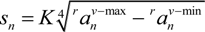
Different step length estimation algorithms have been compared in [8,17]. We use the equation shown in Equation (3):
Jsan 03 00044 i001
where r an is a string of a projected acceleration vector in global coordinate in step n and Jsan 03 00044 i002 and Jsan 03 00044 i003 are the maximum and minimum values of its vertical components, respectively. K is a constant determined by training.
Principal component analysis (PCA)-based step axis estimation is favored because of its robustness. We use an improved PCA-based algorithm to estimate the direction, as described in [33]. It is worth noting that the best performance of step direction estimation is restricted by the sensor’s orientation estimation. Erroneous orientation estimation eventually results in error in direction estimation, regardless of the applied direction estimation method. We only consider 2D movement.
An example of the performance of the pure step-counting algorithm is given in Figure 3. A pedestrian is asked to walk along the black line when the sensor is carried in the pocket. The path starts from the lower left corner and finally returns to the starting point. The whole path is around 90 m. The connected red dots denote the estimated positions after each step computed by the pure step counting algorithm. It can be found that the step length estimation is quite accurate. The localization error mainly comes from the error in step direction estimation.
Figure 3. An example of localization results by pure step counting.
Jsan 03 00044 g003

4. Particle Filter and Map Matching

It is useful to incorporate indoor map information to improve the location results. Previous works have applied indoor map information in map filtering techniques, which eliminates location estimates in impossible areas. However, the accumulating error of the step direction will still eventually lead to large uncertainty in the location estimate. Map matching will relieve this problem.

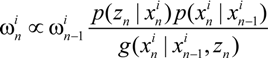
4.1. Particle Filter

The particle filter is normally implemented to apply the map filtering technique. The PF implements a recursive Bayesian filter using the Sequential Monte-Carlo method. It is particularly useful in solving non-linear and non-Gaussian problems. A set of random samples with weights, called particles, are used to represent the posterior probability density of the state, which is given by:
Jsan 03 00044 i004
where xn and z1:n are the state and measurement, respectively, { Jsan 03 00044 i005
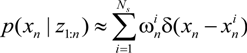
, i = 1,…, Ns} is a set of supporting particles at time n with the associated weights { Jsan 03 00044 i006, i = 1,…, Ns}. Ns are set to 100 in our algorithm.
The weight update equation is given by Equation (5), where Jsan 03 00044 i007 is the importance density.
Jsan 03 00044 i008
In the step counting algorithm, the system update and measurement update are executed after each step. During the system update phase,
Jsan 03 00044 i005 = Jsan 03 00044 i009 + sndn + Jsan 03 00044 i010
where Jsan 03 00044 i005 and Jsan 03 00044 i009 are the 2D states after n steps and n − 1 steps, respectively, and sn and dn are step-n’s length and direction, respectively. Jsan 03 00044 i010 is a random variable with Gaussian distribution.
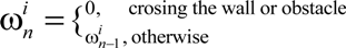
A rule for pedestrian walking is that a pedestrian cannot walk through walls or obstacles. Particles with this motion are seen as invalid, so the weight is updated according to the following equation:
Jsan 03 00044 i011

4.2. Map Matching

Step direction estimation error results in large localization errors. To reduce the direction estimation error, we propose a map matching algorithm to calibrate the estimate when the user is walking in a corridor.
A corridor has two possible directions. Suppose one direction of the corridor is dc; if the following conditions are met, the user is seen as walking along the corridor.
Condition-1: Suppose six consecutive steps are with directions {dn − j, j = 0, 1,…5}, the variance{dn − j, j = 0, 1,…5} < threshold_1.
Condition-2: Suppose the corridor is represented as line segment, c; the distances from the locations of the six steps to c are {Ln j, j = 0, 1,…5}, respectively, Jsan 03 00044 i012.
Condition-3: The average direction Jsan 03 00044 i013 should meet ||dot(davg, dc)|| < threshold_3, where dot(.) means the dot product.
Condition-1 ensures that the pedestrian walks straight, which is the typical pattern when people walk in a corridor. Condition-2 ensures that the track of the pedestrian is close to the corridor. Condition-3 is based on the fact that the error in direction estimation is with a limited angle. These three conditions ensure that the person is walking along a corridor, and even in the worst case that he or she is not, the resulting error is limited by the conditions. After that, the direction with 180° ambiguity is chosen by Equation (8), as the error in direction estimation will not exceed 90°.
Jsan 03 00044 i014
Large errors in direction estimation occur when the pedestrian is making a turn. Therefore, the estimates from the last turn to the current step need to be calibrated (based on at most the previous 20 steps), if the projections of their locations to a corridor (represented as c) are within the corridor ends. Suppose the estimation of the previous Nt steps need to be calibrated, the projection of location xn−Nt to corridor c is xc, n−Nt; then, let xn−Nt = xc, n−Nt.
In 2D space, a counter clockwise rotation of a vector through angle ψ along the x-axis is represented using the rotation matrix Jsan 03 00044 i015
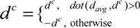
, and the rectified directions { Jsan 03 00044 i016, j = 0, 1,… Nt − 1} are solved using:
Jsan 03 00044 i017
The locations are then calibrated by Equation (10) using the rectified direction estimate.
xn−j = xn−j−1 + sn−j Jsan 03 00044 i016
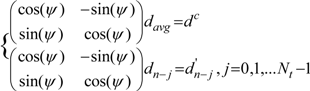
, j = Nt − 1,…, 1, 0
The sensor’s orientation estimate, q, is also calibrated. The counter clockwise rotation with angle ψ in 2D space is rotating along the z-axis for ψ in 3D space.
Jsan 03 00044 i018
Unlike PF being executed at every step, the MM algorithm is triggered only when a pedestrian is considered to be walking along a certain corridor. Our simulation shows that to return the tracking results for the same route, MM based on the step counting algorithm takes 1/6 the CPU time compared to the one using the PF (100 particles).
A performance comparison of the pure step counting and the one with MM is shown in Figure 4. There are narrow corridors in the map. At the beginning, MM is not triggered, so both algorithms achieve the same results. After 43 steps, the conditions of MM algorithm are met, and it is triggered. Turning step 34 is found, whose location is then projected to the corridor, as the one stated in red text. The directions from step 34 to 43 are rectified, and the positions are recalculated. Since the sensor’s orientation estimation is also rectified, so the direction estimation after step 43 is also improved.
Figure 4. Performance comparison of pure step counting and the one with map matching.
Jsan 03 00044 g004

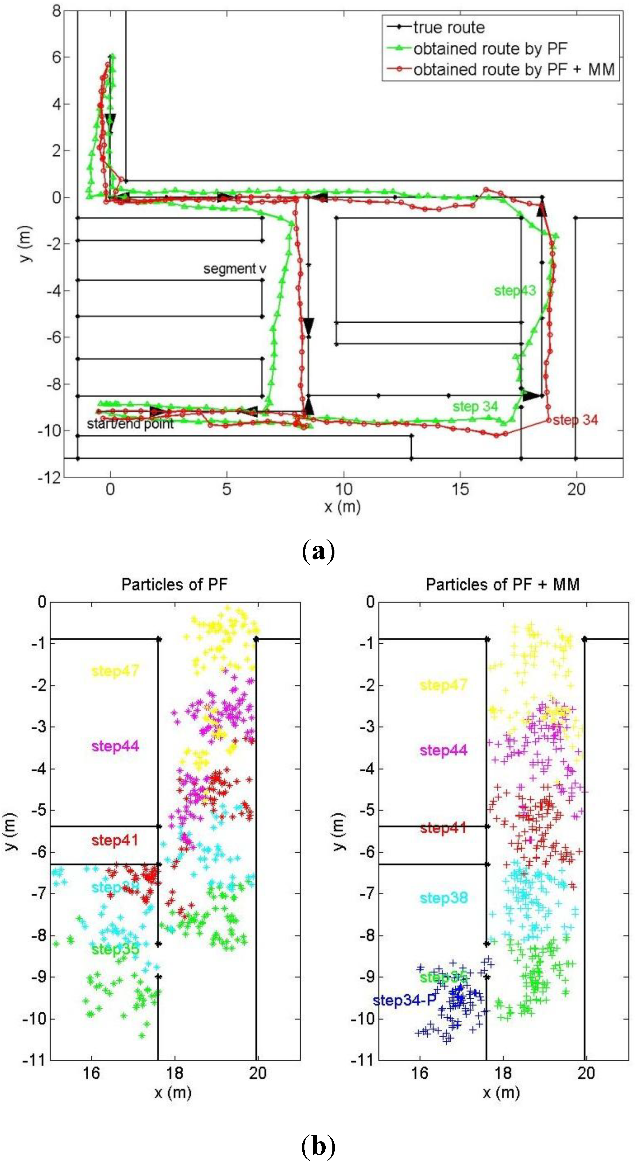
4.3. Particle Filter + Map Matching

Although the MM algorithm provides reliable results with less CPU cost, the required narrow corridors may not always exist in an indoor environment. In addition, it does not require full use of the map information. Moreover, the administrator needs to manually state the coordinates and directions of the selected corridors. Therefore, it is better to perform the MM as a supplementary algorithm to other techniques, rather than as a primary technique.
In this paper, we apply an MM- on PF-based step counting algorithm, which is called MM-enabled PF. Suppose the location of a turning step is xn−Nt and its projection to the corridor (represented as c) is xc, n−Nt; then, the particles of step n−Nt ( Jsan 03 00044 i019) are regenerated with the mean xc, n−Nt.
The particles for the subsequent steps are updated by Equation (12) using the rectified direction estimation. The weight update rule remains the same.
Jsan 03 00044 i020
A performance comparison between the original PF and the MM-enabled PF is shown in Figure 5. In the segment v in Figure 5a, there is clear drift for the PF algorithm, because of the error in step direction estimation. A more detailed explanation of the process is shown in Figure 5b, which represents the particles at different steps as dots with different colors. The particles for PF are sparsely distributed, so that there are always particles in the actual location. Although erroneous particles are filtered during walking, there is a trend that the particles drift to the right-hand side. For the PF + MM algorithm, the MM is triggered in step 43, and the particles are recalculated from step 34. The particles at step 34 for the PF + MM algorithm before the execution of the MM algorithm are also represented (step 34-P)). Once the MM algorithm is triggered, all the particles of step 34-P are regenerated in the corridor. The particles at the subsequent steps are recalculated using the rectified direction estimation, as shown in Figure 5b.
Figure 5. Performance comparison of particle filter (PF) and PF + MM (map matching).
Jsan 03 00044 g005

5. Improved Particle Filter

In this section, we propose an improved particle filter that models the localization error better than the original one and, thus, returns more accurate results. From the previous discussion, it is known that the step direction estimation always suffers from the error in the sensor’s orientation estimation. Because of the uniqueness of the Earth’s gravity, reliable vertical and horizontal components of acceleration are decomposed, which turns out to be accurate step length estimation using Equation (3). Therefore, the position update equation for PF can be written as:
Jsan 03 00044 i021
where n Jsan 03 00044 i022 and n Jsan 03 00044 i023 represent the noise in length and direction estimation, respectively. b Jsan 03 00044 i023 is to compensate the direction estimation drift for particle i in step n, which will be explained later.
To further explain the algorithm, the performance of the pure step counting algorithm shown in Figure 3 needs to be examined. It shows that when a pedestrian walks along a straight line, the pure step counting algorithm provides quite consistent direction estimation, which can be seen as a line. Additionally, there is clear direction drift during the turn.
Because of the robustness of the length estimation and direction estimation during line-mode walk, n Jsan 03 00044 i022 and n Jsan 03 00044 i023 are set as Gaussian variables with small variance. Suppose, initially, the direction estimation is accurate, so that Jsan 03 00044 i0241 = 0. b Jsan 03 00044 i023 is updated as follows:
Jsan 03 00044 i025
where N(0,var) is a Gaussian variable with larger variance. The particle weight is updated also using Equation (7).
For the original PF, the estimated direction always equals dn. Although impossible paths can be eliminated by the accessibility constraints, the error in direction estimation accumulates. In the end, the model in Equation (6) becomes unsuitable for describing the walk process. The advantage of the improved PF is that it incorporates the uncertainty in direction estimation, which is represented as b Jsan 03 00044 i023 and n Jsan 03 00044 i023. The choice of its value is further refined by the pattern that large uncertainty occurs during turning. In this way, this model describes the pedestrian walk better than the previous one. Impossible paths, as well as erroneous directions can be eliminated in this algorithm.
A performance comparison between the previous original PF and our improved PF is shown in Figure 6. There is not much difference in performance when the pedestrian is walking along the corridors. However, in segment v, the original PF shows a clear drifted path, as shown in Figure 6a. This drift comes from the error in direction estimation. Our improved PF, on the other hand, fits the true route quite well, as the drift is compensated for in the model. The particles with erroneous drift estimates are eliminated, as they pass the walls or obstacles. Detailed observation in segment v can be found in Figure 6b, where the particles are drawn. The particles are drawn every three steps, so that the particles from different steps would be easy to distinguish. The particles from different steps are represented using different colors. A clear drift trend can be found for the particles from the original PF algorithm compared to our improved one. It does not learn from the previous filtering results. The improved PF, on the other hand, always eliminates the erroneous b Jsan 03 00044 i023 estimation in the direction estimation and retains the correct ones. Compared to the MM algorithm, the improved PF rectifies the direction estimation without specifically defining the corridors. Its CPU cost is the same as the original PF, which is less than the MM-enabled PF algorithm.
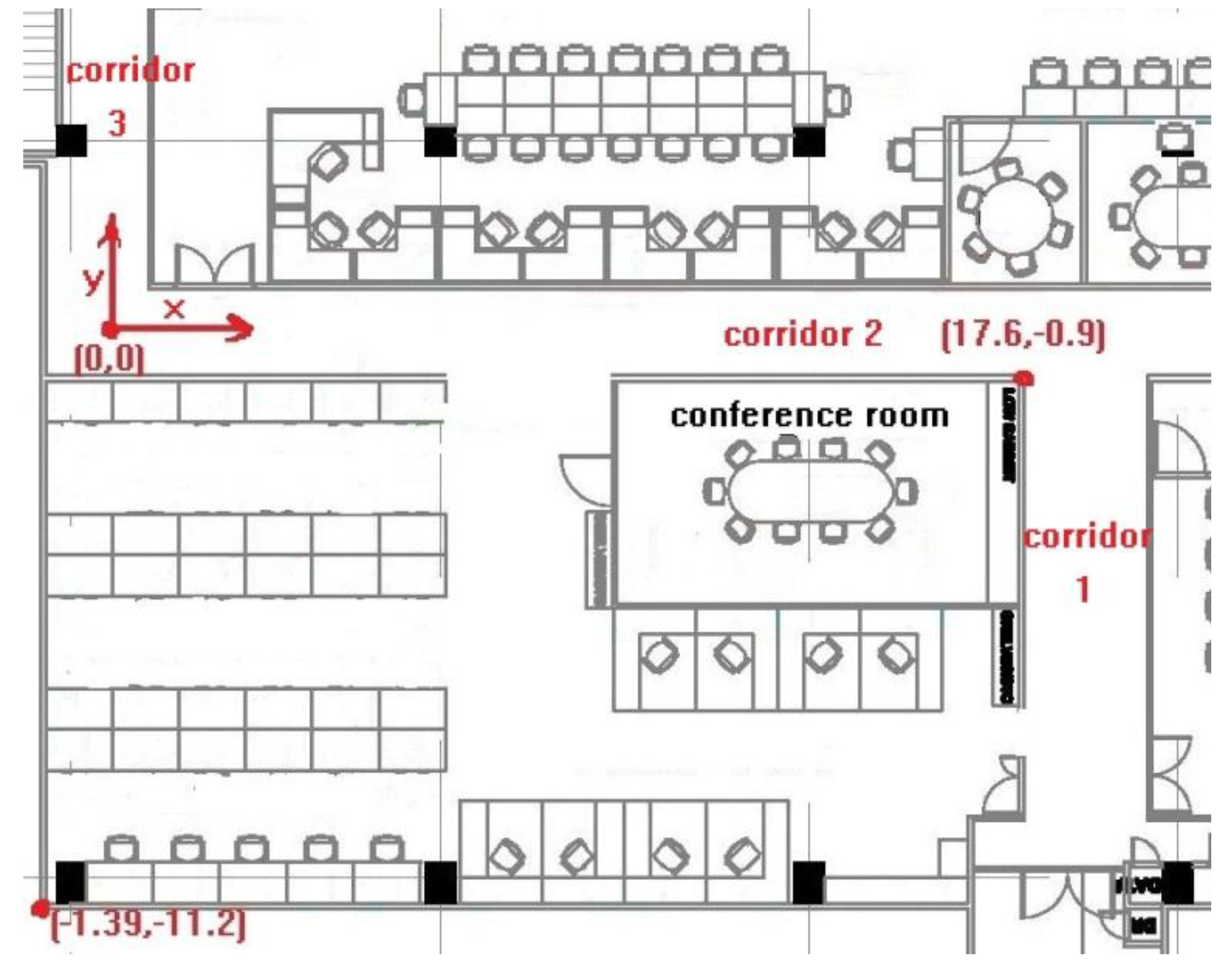
Figure 6. Performance comparison of PF and the improved PF.
Jsan 03 00044 g006

6. Evaluation

Two routes are chosen for the experiment. For each route, 10 trials of data are collected when a pedestrian walks along each route with a motion sensor. Whenever a certain point in the walking path is being passed, the timestamp of the passing is saved. There are 31 pieces of ground truth with timestamps for each route, 1 and 2.

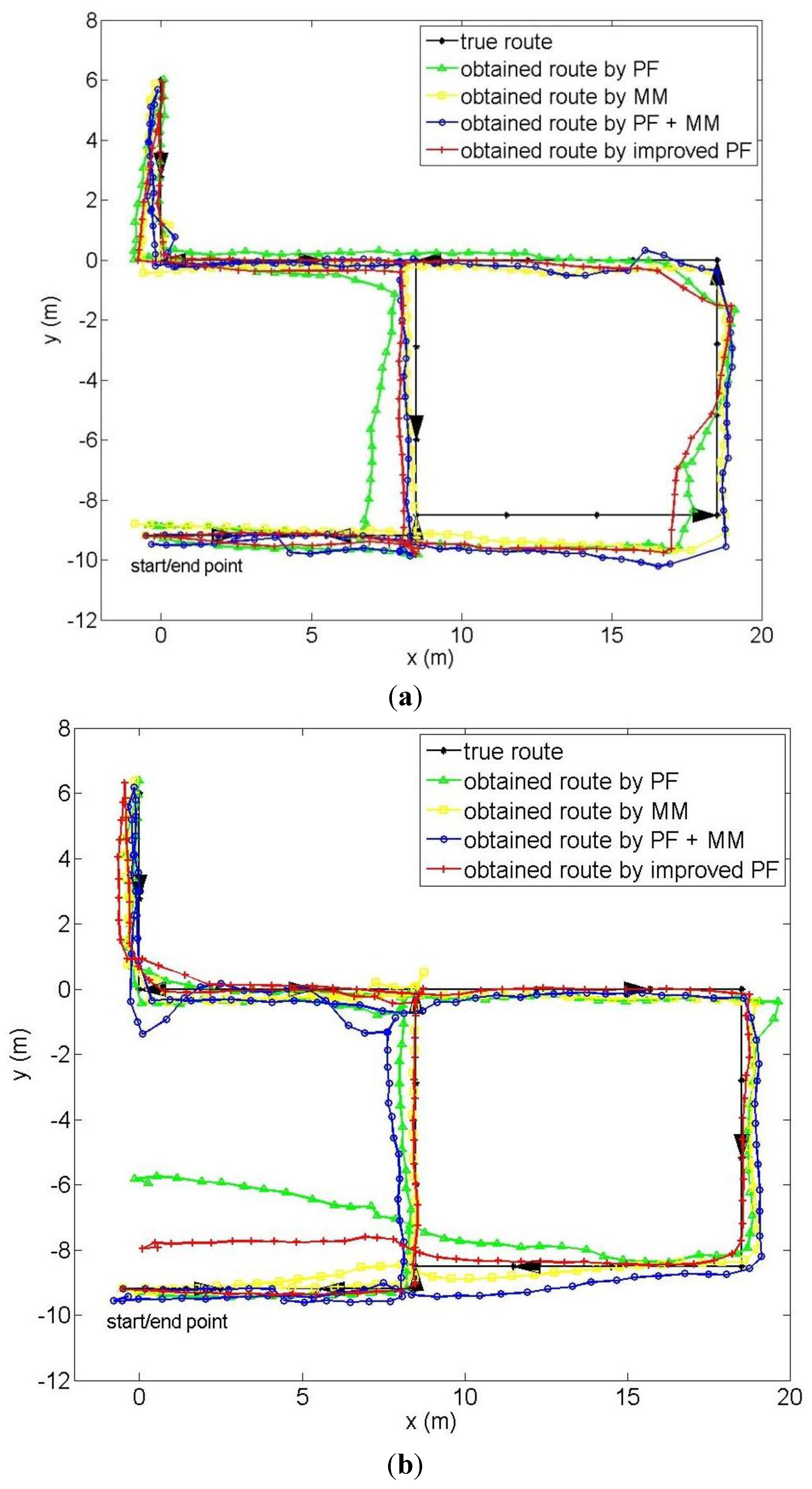
6.1. Performance on Full Map Information

Figure 7 shows an example of the tracking results when different algorithms are applied for routes 1 and 2. In both routes, the start and end points are kept the same; the difference is that the direction in route 1 is counter clockwise, while the one in route 2 is clockwise. The indoor map constraints are kept the same as in the previous example. It is shown that the fused PF and MM algorithms do improve the performance of the direct step counting algorithm. If we compare the paths obtained by the original PF and MM schemes, it can be found that the one from MM coincides better with the ground truth, especially in the area right after the MM gets executed. That is because the PF only rectifies the current location; the error in the sensor’s orientation estimation and the step direction estimation remains in future calculations. The MM algorithm, in contrast, calibrates the location, as well as the sensor’s orientation and step direction. The error in the location update equation (Equation (1)) is reduced. Our improved PF overcomes the drawback by modelling the error in direction estimation.
Let the localization error be the distance between ground truth and estimated location. The average tracking errors for the 10 trials for each route are shown in Table 1 and Table 2, respectively. The last column shows the average error for the 10 trials. MM returns more accurate results than PF in the 17 trials of the total 20 trials. In the rest of the three trials, the performances are quite close (0.68/0.69, 0.94/1.09 and 1.00/1.01). Therefore, MM outperforms PF in the given map environment. A similar conclusion can be made when we compare the accuracy of MM-enabled PF with PF and the accuracy of our improved PF with PF. PF provides the least accuracy among the three, which is only better than pure step counting without map constraints. When we compare the average error from MM, MM-enhanced PF and improved PF, we see quite close location accuracy.
Figure 7. An example of the tracked results for route 1 and 2 given different algorithms.
Jsan 03 00044 g007
Table 1. Average (Avg) error for each trial (route 1).
Applied
Methods
Average Error (m)
12345678910Avg
Step counting1.311.161.221.632.020.900.971.710.862.031.38
PF1.040.820.770.860.601.460.731.090.680.720.88
MM0.490.590.620.440.410.650.700.830.690.600.60
PF + MM0.680.670.610.680.680.750.600.860.880.770.72
Improved PF0.620.410.560.470.580.560.390.750.510.680.55
Table 2. Average error for each trial (route 2).
Applied
Methods
Average Error (m)
12345678910Avg
Step counting1.711.100.951.471.151.111.361.321.251.561.30
PF0.940.840.930.941.570.810.911.011.001.061.00
MM0.750.580.861.091.520.650.610.731.010.850.87
PF + MM0.480.720.781.141.270.500.580.720.860.750.78
Improved PF0.970.680.741.151.370.750.840.730.971.120.93
It is interesting to find that the MM-enabled PF does not further improve the performance. That is because there are many corridors in our map for MM to take effect, and the paths are along the corridors. MM alone is sufficient to obtain good results.
MM is triggered only when the pedestrian is in the corridor, which wastes the other map constraints’ information. MM-enabled PF is quite a natural method to retain the advantages of both algorithms. Our improved PF takes advantage of PF and improves direction estimation at the same time. In the next section, when less corridor information is given, we will see the improvement of such algorithms.

6.2. Performance on Incomplete Map Information

Previous evaluation has been carried out in an ideal corridor environment, like our lab. It is necessary to test the performance in another scenario. In this paper, the new scenario is virtually created by giving incomplete map information to the algorithms. From the algorithms’ perspective, it makes no difference compared to collecting the data in a physical new environment and using relative map constraints. Figure 8 shows the incomplete map we use to evaluate the performance for the same routes in Section 6.1. Map 1 keeps the map constraints in the top left corner, with one wall of a horizontal corridor. Map 2 keeps the map constraints in the bottom right corner, with the conference room.
Figure 8. The incomplete map used.
Jsan 03 00044 g008
The average accuracy for each of the trials with respect to the route and map are presented in Table 3, Table 4, Table 5 and Table 6. Table 7 shows the average error for map 1 and map 2 and the overall average. We first notice that PF no longer provides better results than the pure step counting algorithm. This is because in the settings with few map constraints, the particles are widely spread out without calibration. The tracking may have been misled to a drifted path if the pedestrian encounters an obstacle in that case.
There is slight enhancement for MM and MM-enhanced PF, compared to step counting. Although from the average value, MM-enhanced PF performs worse than MM (1.31 m to 1.26 m), we find that MM-enhanced PF actually provides more robust results. When MM returns large error in trial 5 in Table 3 (2.17 m), trial 7 in Table 4 (2.01 m) and trial 1 in Table 6 (2.32 m), MM-enhanced PF dramatically reduces the error (0.86, 0.83 and 1.80, respectively). The proposed improved PF achieves the most accurate result among all the algorithms with the same computational complexity as the original PF. Considering there is no additional requirement on the manually provided corridor information, improved PF is the most robust solution in various map scenarios.
Table 3. Average error for each trial (map 1, route 1).
Applied
Methods
Average Error (m)
12345678910
Step counting1.311.161.221.632.020.900.971.710.862.03
PF1.781.281.541.461.091.221.001.301.681.21
MM0.961.221.071.902.171.080.921.640.901.80
PF + MM1.651.221.421.200.861.381.381.241.281.24
Improved PF1.251.021.271.070.991.071.120.991.001.14
Table 4. Average error for each trial (map 1, route 2).
Applied
Methods
Average Error (m)
12345678910
Step counting1.711.100.951.471.151.111.361.321.251.56
PF1.901.061.541.411.561.701.241.781.611.75
MM1.031.651.051.471.360.862.010.750.990.99
PF + MM2.000.811.621.471.631.740.831.611.831.79
Improved PF1.620.771.211.071.281.520.861.061.271.37
Table 5. Average error for each trial (map 2, route 1).
Applied
Methods
Average Error (m)
12345678910
Step counting1.311.161.221.632.020.900.971.710.862.03
PF1.751.481.642.081.741.191.431.931.551.90
MM2.320.921.800.551.090.840.971.101.910.95
PF + MM1.801.011.360.890.871.051.171.131.621.05
Improved PF1.570.700.921.091.641.071.241.521.151.38
Table 6. Average error for each trial (map 2, route 2).
Applied
Methods
Average Error (m)
12345678910
Step counting1.711.100.951.471.151.111.361.321.251.56
PF1.381.290.881.451.481.211.031.371.211.26
MM1.410.771.031.291.310.971.011.431.141.84
PF + MM1.410.651.040.991.541.440.871.351.101.67
Improved PF1.581.260.911.491.431.191.210.891.141.31
Table 7. Average error for each map and overall.
Average OverError for Applied Methods (m)
Step CountingPFMMPF + MMImproved PF
Map 11.341.461.291.411.15
Map 21.341.461.231.201.23
Overall1.341.461.261.311.19

7. Conclusion

In this paper, a step counting algorithm with MM-enabled PF, as well as one with improved PF is introduced. Compared to existing works that apply PF to eliminate the particles with impossible locations, our algorithm calibrates not only the location, but also the sensor’s orientation and step direction, which reduces the error in the location update computation. To further improve the algorithm by avoiding specified corridor information, an improved PF is proposed, which calibrates the step direction estimation during map filtering. The algorithm has been evaluated experimentally in our laboratory using an in-pocket motion sensor. Experimental results have shown that in a dense map constraint environment with corridors, MM, MM-enabled PF and improved PF outperform the original PF. When partial map constraints are applied, the advantage of using the improved PF is shown, which returns more accurate and robust results. Furthermore, considering that the improved PF does not require the user to specify the corridor information, it is the most adaptive algorithm for various indoor environments.

Acknowledgments

This research was carried out at the National University of Singapore-Zhejiang University (NUS-ZJU) Sensor-Enhanced Social Media (SeSaMe) Centre. It is supported by the Singapore National Research Foundation under its International Research Centre at the Singapore Funding Initiative and administered by the Interactive Digital Media Programme Office.

Conflicts of Interest

The authors declare that there is no conflict of interests regarding the publication of this article.

References

  1. Otsason, V.; Varshavsky, A.; LaMarca, A.; Lara, E.D. Accurate GSM Indoor Localization. In Proceedings of the International Conference on Ubiquitous Computing, Tokyo, Japan, 11–14 September 2005; pp. 141–158.
  2. Manodham, T.; Loyola, L.; Miki, T. A novel wireless positioning system for seamless internet connectivity based on the WLAN infrastructure. Wirel. Pers. Commun. 2008, 44, 295–309. [Google Scholar] [CrossRef]
  3. Lin, H.H.; Tsai, C.C.; Hsu, J.C. Ultrasonic localization and pose tracking of an autonomous mobile robot via fuzzy adaptive extended information filtering. IEEE Trans. Instrum. Meas. 2008, 57, 2024–2034. [Google Scholar] [CrossRef]
  4. Wendlandt, K.; Berbig, M.; Robertson, P. Indoor Localization with Probability Density Functions Based on BLUETOOTH. In Proceedings of the IEEE International Symposium on Personal Indoor and Mobile Radio Communications, Berlin, Germany, 11–14 September 2005; pp. 2040–2044.
  5. Jin, Y.; Toh, H.; Soh, W.S.; Wong, W.C. A Robust Dead-Reckoning Pedestrian Tracking System with Low Cost Sensors. In Proceedings of the IEEE International Conference on Pervasive Computing and Communications, Seattle, WA, USA, 21–25 March 2011; pp. 222–230.
  6. Kourogi, M.; Kurata, T. Personal Positioning Based on Walking Locomotion Analysis with Self-Contained Sensors and a Wearable Camera. In Proceedings of the 2nd IEEE and ACM International Symposium on Mixed and Augmented Reality, Tokyo, Japan, 7–10 October 2003; pp. 103–112.
  7. Ladetto, Q. On Foot Navigation: Continuous Step Calibration Using both Complementary Recursive Prediction and Adaptive Kalman Filtering. In Proceedings of the ION GPS 2000, Salt Lake, UT, USA, 19–22 September 2000; pp. 1735–1740.
  8. Kim, J.W.; Jang, H.J.; Hwang, D.H.; Park, C. A Step, Stride and Heading Determination for the Pedestrian Navigation System. In Proceedings of the International Symposium on GNSS/GPS, Sydney, Australia, 6–8 December 2004.
  9. Krach, B.; Roberston, P. Cascaded Estimation Architecture for Integration of Foot-Mounted Inertial Sensors. In Proceedings of the 2008 IEEE/ION Position Location and Navigation Symposium, Monterey, CA, USA, 5–8 May 2008; pp. 112–119.
  10. Klepal, M.; Beauregard, S. A Backtracking Particle Filter for Fusing Building Plans with PDR Displacement Estimates. In Proceedings of the 5th Workshop on Positioning Navigation and Communication, Hannover, Germany, 27 March 2008; pp. 207–212.
  11. Afzal, M.H.; Renaudin, V.; Lachapelle, G. Use of earth’s magnetic field for mtigating gyroscope errors regardless of magnetic perturbation. Sensors 2011, 11, 11390–11414. [Google Scholar] [CrossRef]
  12. Afzal, M.H.; Renaudin, V.; Lachapelle, G. Assessment of Indoor Magnetic Field Anomalies Using Multiple Magnetometers. In Proceedings of the ION GNSS 2010, Session F1. Portland, OR, USA, 21–24 September 2010.
  13. ADIS16400/16405 Data Sheet. Available online: http://www.analog.com/static/imported-files/data_sheets/ADIS16400_16405.pdf (accessed on 10 December 2013).
  14. Ichikawa, F.; Chipchase, J.; Grignani, R. Where’s the Phone? A Study of Mobile Phone Location in Public Spaces. In Proceedings of the 2nd International Conference Mobile Technology Applications and Systems, Guangzhou, China, 15–17 November 2005; p. 142.
  15. Lee, S.W.; Mase, K. Activity and location recognition using wearable sensor. IEEE Pervasive Comput. 2002, 1, 24–32. [Google Scholar] [CrossRef]
  16. Roetenberg, D.; Slycke, P.J.; Veltink, P.H. Ambulatory position and orientation tracking fusing magnetic and inertial sensing. IEEE Trans. Biomed. Eng. 2007, 54, 883–890. [Google Scholar] [CrossRef]
  17. Alvarez, D.; Gonzalez, R.C.; Lopez, A.; Alvarez, J.C. Comparison of step length estimators from wearable accelerometer devices. Int. Conf. IEEE Eng. Med. Biol. Soc. 2006, 1, 5964–5967. [Google Scholar]
  18. Blanke, U.; Schiele, B. Sensing Location in the Pocket. In Proceedings of Ubiquitous Computing 2008, Seoul, Korea, 21–24 September 2008.
  19. Steinhoff, U.; Schiele, B. Dead Reckoning from the Pocket—An Experimental Study. In Proceedings of the 8th Annual IEEE International Conference in Pervasive Computing and Communications, Mannheim, Germany, 29 March–2 April 2010; pp. 162–170.
  20. Kunze, K.; Lukowicz, P.; Partridge, K.; Begole, B. Which Way Am I Facing: Inferring Horizontal Device Orientation from an Accelerometer Signal. In Proceedings of the International Symposium on Wearable Computers, Linz, Austria, 4–7 September 2009; pp. 149–150.
  21. Jang, H.J.; Kim, J.W.; Hwang, D.H. Robust step detection method for pedestrian navigation systems. Electron. Lett. 2007, 43. [Google Scholar] [CrossRef]
  22. Li, X.; Zhou, Q.; Lu, S.; Lu, H. A New Method of Double Electric Compass for Localization in Automobile Navigation. In Proceedings of the 2006 IEEE International Conference on Mechatronics and Automation, Luoyang, China, 25–28 June 2006; pp. 514–519.
  23. Roetenberg, D.; Luinge, H.J.; Baten, C.T.M.; Veltink, P.H. Compensation of magnetic disturbances improves inertial and magnetic sensing of human body segment orientation. IEEE Trans. Neural Syst. Rehabil. Eng. 2005, 13, 395–405. [Google Scholar] [CrossRef]
  24. Roetenberg, D.; Baten, C.T.M.; Veltink, P.H. Estimating body segment orientation by applying inertial and magnetic sensing near ferromagnetic materials. IEEE Trans. Neural Syst. Rehabil. Eng. 2007, 15, 469–471. [Google Scholar] [CrossRef]
  25. Kemppi, P.; Rautiainen, T.; Ranki, V.; Belloni, F.; Pajunen, J. Hybrid Positioning System Combining Angle-Based Localization, Pedestrian Dead Reckoning and Map Filtering. In Proceedings of the 2010 International Conference on Indoor Positioning and Indoor Navigation, Zurich, Switzerland, 15–17 September 2010; pp. 1–7.
  26. Davidson, P.; Collin, J.; Takala, J. Application of Particle Filters for Indoor Positioning Using Floor Plans. In Proceedings of the Ubiquitous Positioning Indoor Navigation and Location Based Service, Kirkkonummi, Finland, 14–15 October 2010; pp. 1–4.
  27. Vildjiounaite, E.; Malm, E.J.; Kaartinen, J.; Alahuhta, P. Location Estimation Indoors by Means of Small Computing Power Devices, Accelerometers, Magnetic Sensors, and Map Knowledge. In Pervasive Computing; Springer: Berlin/Heidelberg, Germany, 2002; Volume 2414, pp. 211–224. [Google Scholar]
  28. Spassov, I.; Bierlaire, M.; Merminod, B. Map Matching for Pedestrians via Bayesian Inference. In Proceedings of the European Navigation Conference—Global Navigation Satellite Systems, Manchester, UK, 7–10 May 2006.
  29. Quddusa, M.A.; Ochiengb, W.Y.; Nolandb, R.B. Current map-matching algorithms for transport applications: State-of-the art and future research directions. Transp. Res. Part C Emerg. Technol. 2007, 15, 312–328. [Google Scholar] [CrossRef] [Green Version]
  30. Bao, H.; Wong, W.C. An Indoor Dead-Reckoning Algorithm with Map Matching. In Proceedings of the IEEE International Wireless Communications and Mobile Computing Conference, Cagliari, Italy, 1–5 July 2013; pp. 1534–1539.
  31. Yun, X.; Bachmann, E.R.; McGhee, R.B. A simplified quaternion-based algorithm for orientation estimation from earth gravity and magnetic field measurements. IEEE Trans. Instrum. Meas. 2008, 57, 638–650. [Google Scholar] [CrossRef]
  32. Choukroun, D.; Itzhack, I.Y.B.; Oshman, Y. Novel quaternion Kalman filter. IEEE Trans. Aerosp. Electron. Syst. 2006, 42, 174–190. [Google Scholar] [CrossRef]
  33. Bao, H.; Wong, W.C. Improved PCA Based Step Direction Estimation for Dead-Reckoning. In Proceedings of the 2nd International Workshop on Smart Sensor, Beijing, China, 10–12 October 2013.

