
Performance Evaluation of LoRa Communications in Harsh Industrial Environments

1
Multidisciplinary Laboratory of Research and Innovation, Moroccan School of Engineering Sciences, Casablanca 20250, Morocco
2
Laboratory of Advanced Systems Engineering, National School of Applied Sciences, Ibn Tofail University Campus, Kenitra 14000, Morocco
*
Author to whom correspondence should be addressed.
J. Sens. Actuator Netw. 2023, 12(6), 80; https://doi.org/10.3390/jsan12060080
Submission received: 4 October 2023
/
Revised: 27 October 2023
/
Accepted: 1 November 2023
/
Published: 28 November 2023
(This article belongs to the Section Communications and Networking)
Abstract
:LoRa technology is being integrated into industrial applications as part of Industry 4.0 owing to its longer range and low power consumption. However, noise, interference, and the fading effect all have a negative impact on LoRa performance in an industrial environment, necessitating solutions to ensure reliable communication. This paper evaluates and compares LoRa’s performance in terms of packet error rate (PER) with and without forward error correction (FEC) in an industrial environment. The impact of integrating an infinite impulse response (IIR) or finite impulse response (FIR) filter into the LoRa architecture is also evaluated. Simulations are carried out in MATLAB at 868 MHz with a bandwidth of 125 kHz and two spreading factors of 7 and 12. Many-to-one and one-to-many communication modes are considered, as are line of sight (LOS) and non-line of Sight (NLOS) conditions. Simulation results show that, compared to an environment with additive white Gaussian noise (AWGN), LoRa technology suffers a significant degradation of its PER performance in industrial environments. Nevertheless, the use of forward error correction (FEC) contributes positively to offsetting this decline. Depending on the configuration and architecture examined, the gain in signal-to-noise ratio (SNR) using a 4/8 coding ratio ranges from 7 dB to 11 dB. Integrating IIR or FIR filters also boosts performance, with additional SNR gains ranging from 2 dB to 6 dB, depending on the simulation parameters.
Keywords:
LoRa; industrial environment; industrial noise; interference; fading; FEC; IIR filter; FIR filter; LOS; NLOS1. Introduction
Wireless communication has become an essential part of Industry 4.0. It enables greater flexibility and connectivity for devices, machines, and connected devices [1]. With the rise of the Industrial Internet of Things (IIoT), wireless communication has become even more important for Industrial applications [2]. The IIoT connects billions of devices and objects via wireless communication networks. This enables real-time data collection, advanced data analysis via artificial intelligence, and the digitization of industrial processes [3].
Today, low-power wideband networks have become the paradigm of the IIoT ecosystem [4]. They have attracted the interest of industrial companies by efficiently connecting energy-saving devices, offering high autonomy, and covering large areas with extended range, thus requiring minimal maintenance [5]. LoRa is an LPWAN network technology widely used in industrial applications. By 2026, according to ABI Research, over 50% of LPWAN connections will use LoRa, thanks to its flexibility for indoor and outdoor applications [6]. It enables low-speed data transmission over long distances with low power consumption and minimal infrastructure [7]. It is used in machine monitoring, asset tracking, energy management, and environmental monitoring [8,9,10,11,12]. However, the quality of data transmission via LoRa can be affected by environmental constraints [13]. Multiple obstacles, high temperatures, Humidity, excessive dust, and particles, as well as the presence of metallic equipment, make it difficult to transmit data over long or medium distances [14,15,16,17]. This leads to insufficient bandwidth and throughput to reach the sensors [18]. It is used in machine monitoring, asset tracking, energy management, and environmental monitoring [8,9,10,11]. However, the quality of data transmission via LoRa can be affected by environmental constraints [13]. Multiple obstacles, high temperatures, humidity, excessive dust, and particles, as well as the presence of metallic equipment, make it difficult to transmit data over long or medium distances [14,15,16,17]. This leads to insufficient bandwidth and throughput to reach the sensors [18].
Indeed, the implementation of wireless communications in industrial environments can be complex due to several factors [14,19,20,21,22]. On the one hand, interference resulting from signal reflection, echoes, and multipath attenuation causes alterations in transmissions. These interferences are caused by obstacles or reflective surfaces, resulting in multipath propagation. In addition, the presence of other wireless devices operating in the same frequency range also contributes to this interference, impacting overall communication performance. On the other hand, electromagnetic emissions from various industrial sources, such as heavy machinery, powerful generators, lasers, etc., generate high noise levels that disrupt wireless communications. This makes communication between transmitters and receivers difficult, resulting in data loss. Atmospheric conditions, such as temperature and humidity, present a further challenge to wireless communications by altering signal propagation. Extremely high or low temperatures affect receiver sensitivity and transmitter stability, resulting in reduced range and signal quality. The use of LoRa as a wireless technology is limited by these factors in many industrial scenarios, although LoRa holds great promise for the industry. As a result, evaluating the performance of LoRa technology in these environments is of vital importance for improving the reliability of data sent and optimizing communication networks for critical industrial applications.
In this work, we explore and highlight the potential and challenges of LoRa technology within industrial environments, relying on rigorous MATLAB simulations. Our exploration covers both LOS and NLOS communication conditions, looking at two crucial industrial communication modes: many to one, in which several transmitters send data to a single receiver, and one to many, in which a single transmitter sends data to several receivers. Several parameters were considered in the simulations. These included the use of an 868 MHz frequency band, a 125 kHz bandwidth, two spreading factors (7 and 12), and two coding rates (4/5 and 4/8). In addition, two channel types were used to obtain results closer to the real environment. The results demonstrate a clear advantage of forward error correction (FEC), based on the Hamming code built into LoRa’s physical layer: for a coding rate of 4/8, LoRa sees its PER performance improve considerably, with impressive SNR gains ranging from 7 dB to 11 dB. But the contribution doesn’t stop there. By integrating an IIR or FIR filter into the LoRa architecture, we observe additional SNR gains ranging from 2 to 6 dB, although the optimal choice between these filters is intrinsically linked to the specific needs of the industrial environment in question. Taken together, these contributions illustrate LoRa’s robustness in demanding industrial scenarios while providing a framework for maximizing its performance.
This paper is organized as follows: Section 2 presents a review of the most significant work on the evaluation of LoRa technology in industrial environments. Section 3 takes a deeper look at LoRa technology as well as channel and noise interactions. In Section 4, forward error correction based on Hamming error correction, as well as IIR and FIR filters, are discussed. Section 5 scrutinizes the modulation and demodulation processes of LoRa, particularly in the context of noisy channel conditions. In Section 6, the spotlight is on evaluating LoRa’s performance, with a keen focus on forward error correction using hamming error correction, complemented by an exploration of filtering methods. The paper draws to a close with Section 7, encapsulating the primary conclusions and hinting at prospective avenues for subsequent research in this field.
2. Related Work
The ability to provide long-range communication at low power consumption makes LoRa technology a wise choice for IIoT applications. However, industrial environments are often noisy, with sources of electromagnetic noise such as electronic equipment, communications equipment, and heavy machinery, which can have a negative impact on the performance of this technology [22]. Studies have been carried out to assess LoRa’s performance in these environments, such as the work in [23], whose authors examined the effect of industrial and AWGN noise on LoRa communication systems. The results showed a significant degradation in signal quality in the presence of impulse noise compared with Gaussian noise, with BER values ranging from to for both types of noise. Furthermore, the results of the study conducted by [24] confirmed that the use of LoRa in multi-propagation mining environments results in a performance reduction of 2.5 to 6 decibels for different spreading factors (SF) at a BER of , compared with the AWGN channel. In the same context, LoRa’s performance was evaluated under various noise conditions by [25], who demonstrated that this technology can maintain robust communication even in noisy environments, making it suitable for a wide range of IoT and IIoT application scenarios. Furthermore, in [26], researchers studied the impact of impulsive noise on Lora communication systems. The results indicated that a higher spreading factor effectively reduces noise impulsiveness after FFT. This led to a notable decrease in SNR loss. Yet, it caused more delay and used more power. In addition, the work done in [19] has shown that LoRa can be used in industrial areas. This research evaluates the operation and applicability of LoRa technology in an industrial environment. The authors considered two factories with different machines and production processes. Measurements were taken in a LOS configuration between sensor nodes and gateways. The results show that the SNR, RSSI, and PER parameters show little degradation in connection quality in the industrial environment analyzed.
Further research has been carried out to evaluate the use of LoRa technology in industrial environments. In this regard, research was done by [14] tested LoRa communication for short-range use. The results showed that the use of this technology had no significant negative impact on reliability or packet loss and that data rates equivalent to 21,875 bps were achieved, which could be sufficient for certain non-critical industrial applications. In [27], the performance of a LoRaWAN network was evaluated in industrial scenarios where IIoT nodes communicate with a central controller to optimize industrial processes and reduce costs. The authors tested different scenarios, including confirmed and unconfirmed traffic, multi-gateway deployments, the use of different device classes, and a non-standard channel plan. The results showed that, with appropriate configuration, LoRaWAN was able to serve IIoT sensing applications with a packet success rate of over 90% and limited communication delays. These results highlight the importance of network configuration for optimum performance in industrial environments.
The presence of obstacles such as tall buildings in harsh environments poses challenges for the implementation of LoRaWAN networks. A research study was carried out [28] to evaluate the propagation characteristics of LoRa communications at 920 MHz in a harsh environment. In this work, the authors measured the average values of the received signal strength indicator (RSSI) on a campus to evaluate the probability of communication failure and the path loss model. The results showed that the harsh environment leads to a reduction in the communication area. The authors in [29] presented a concrete example of the use of LoRa technology in industry in a specific context. In this example, numerous carts need to communicate with a server as they move across an auction floor. The results showed that using a single LoRa gateway can cover an indoor area of around 34,000 with a spreading factor of 7. When the spreading factor is increased to 12, the area covered is even larger and includes the area outside the factory. Their results also showed that a gateway can serve up to 6000 nodes in such a scenario, making it a viable solution for IoT networks in industry. In the same context, a LoRa-based sensor node was evaluated for industrial use by [30] in terms of energy consumption rate and communication reliability in a harsh environment. The results show that the sensor node can operate efficiently with a battery for a long period of time, up to a cut-off voltage of 3.2 V. In addition, despite the harsh environment, the signals received were sufficiently reliable. Thus, a node could be deployed for industrial use with high reliability and lower maintenance costs.
Several studies have been carried out to improve the performance of LoRa technology in industrial environments. The authors of [31] have proposed a real-time LoRa protocol for industrial monitoring and control applications. This protocol is based on a real-time task scheduling algorithm, complemented by a logical slot indexing algorithm for efficient schedule generation. In addition, a node clustering method has been proposed to solve signal fading and suppression problems. The results of tests of this protocol on a platform comprising a gateway and fifteen nodes showed that, despite relatively high traffic (one packet sent every three seconds on average by each node), the transmission success rate (TPR) exceeded 94%, even in the presence of high external interference, such as each interfering node generating one erroneous packet every three seconds. In the same context, another two-hop real-time LoRa protocol has been proposed [32]. This protocol is based on two-hop tree construction, distributed slot planning, and optimal data aggregation. It makes it possible to allocate slots to terminal nodes at one or two hops to meet time constraints, overcome the problem of packet loss, and minimize the number of transmissions to save energy. The protocol can support hundreds of nodes on a single channel and achieve high reliability in data transmissions, regardless of the number of nodes deployed. In addition, the authors in [33] proposed a real-time production monitoring approach based on wireless sensor networks (WSNs) and the LoRa protocol. This approach uses multiple wireless nodes networked with temperature and vibration sensors deployed on conventional manufacturing machines to record operational data for system diagnosis and troubleshooting. It has been implemented and tested on conventional manufacturing equipment in a food production facility. The tests on the prototype system confirmed the capabilities and accuracy of this approach. Another research project focused on the application of a metric called F-QoS to the LoRa network, particularly in complex industrial environments with installations minimizing disturbances [34]. The results indicate robust LoRa performance, despite challenges such as metal obstructions and non-ideal installation conditions. Using F-QoS, the authors also suggest a sampling approach where radio transmissions should be at least three times the desired final sampling rate to ensure data reliability. Moreover, the authors in [35] evaluate LoRaWAN performance with six different ADR algorithms in an industrial context using the FLoRa framework and an Omnet++ testbed. Analyses focus on packet delivery and energy consumption according to gateway position and data traffic. The results reveal that minimizing the link budget under unfavorable channel conditions improves performance, while overestimating channel behavior is detrimental to packet delivery.
In the context of LoRa communications for industrial applications, several studies have explored its various facets, as shown in Table 1. Our work stands out by examining LoRa performance across two architectures, “Many to one” and “One to many”, and in Line of Sight (LOS) and Non-Line of Sight (NLOS) scenarios. The main contribution lies in the optimization of LoRa performance using the Hamming corrector code and the IIR and FIR filters. This contribution aims to enhance transmission reliability in an industrial context, while adding a new dimension to existing LoRa research.
3. LoRa, Channel and Noise
3.1. LoRa: Modulator and Demodulator
In this sub-section, we will present the LoRa modulator and demodulator that we used in the simulations. This presentation is based on the research done in the paper [36], where the authors designed a LoRa emulator.
3.1.1. Modulator
During LoRa transmission, the message is transformed into a series of bits. These bits are then grouped together to form symbols. Each symbol is then modulated using a chirp waveform that is specifically designed to match the symbol in question by encoding its value in its starting frequency. This waveform is created by varying the carrier frequency along a linear path between −B/2 and B/2, where B represents the bandwidth, producing a ramp-like waveform. The length of each symbol is controlled by the spreading factor (SF). This represents symbol values, the duration of each of which is given by the following formula: . Symbols are transmitted in the form of frames, which are structured data packets. Each frame consists of a header, payload data, and an error correction section and can be written as follows:
where N and Sn represent the total number of symbols per frame and the symbol of index n, respectively.
The modulated signal is expressed mathematically by the following equation:
where, B represents the bandwidth, n represents the symbol index, and mn and Ts represent the symbol value and duration, respectively, as illustrated in Figure 1.
In LoRa communications, the spreading factor is a parameter that plays an important role in the quality of data transmission. When the spreading factor is high, transmission is more robust and less sensitive to interference and noise, which increases the transmission range and improves communication reliability. However, one consequence of using a high spreading factor is that data transmission time is longer, which reduces data throughput. In other words, a higher spreading factor enables data to be transmitted over a greater distance with better signal quality, but at the cost of a slower data rate and higher energy consumption.
3.1.2. Demodulator
The transmitted signal propagates in a transmission channel represented by f(s(t)), where s(t) represents the transmitted signal. During this propagation, the signal is affected by noise and interference, represented by n(t) and i(t), respectively. The received signal y(t) can then be expressed as follows:
The received signal is first dechirped by multiplying it by a sequence of inverted chirps c(t) without frequency shifting, as shown in the following equation:
where c(t) is defined as:
If we consider an ideal channel, the received signal is not altered by the function associated with this channel. Consequently, we can conclude that the channel function, represented by f, satisfies f(s(t)) = s(t), so the dechirped signal is defined by the Equation (6):
It is very important to identify the spreading factor and bandwidth of the received LoRa signal prior to the dechirping process. To achieve accurate dechirping, the chirp slope of the received LoRa signal must be identical to that of the dechirped signal, in addition to precise symbol synchronization to ensure accurate dechirping. Once the signal has been dechirped, a fast Fourier transform is used to demodulate it. For non-coherent demodulation, the power spectral density is analyzed to extract the dominant frequency component, which represents the original offset and contains the symbol value information. This is how the LoRa symbol is recovered:
where Y(f) = FFT{y(t)} and S ∈ {0, 1, …, M − 1} is the recovered symbol value.
For coherent demodulation, the frequency shift waveform that maximizes the convolution magnitude represents the estimated symbol as follows:
where Zk (t) is the signal modulated with a frequency offset k/Ts, represented as and k is an integer representing all possible symbols . Figure 2 shows an example of the demodulation of two symbols, providing a visual understanding of the CSS demodulation used by LoRa.
3.2. Channel and Noise
Industrial environments are characterized by high noise levels and more frequent interference than other environments, such as domestic areas and offices. This is due to high operating temperatures, intense vibrations, and excessive electromagnetic noise [37,38]. Also, wireless communication performance can be degraded by the attenuation effect of obstacles and the random movements of objects or people encountered in the propagation path [39].
3.2.1. Channel
Signal transmission over a wireless communication channel is affected by both large-scale and small-scale propagation effects. This propagation is influenced by four fundamental mechanisms, namely spatial dispersion, reflection, refraction, and scattering. A generalized channel model used for wireless communication systems is defined as follows [40]:
where y(t), h(t), n(t), and x(t) represent the received signal, channel impulse response, random noise, and transmitted signal, respectively. Typically, in industrial environments, nodes are arranged in a LOS configuration. The authors in [22,39] carried out several channel propagation measurements in different industrial environments. Their measurements showed that in an industrial environment, the Rice distribution, Rayleigh, and normal Log characteristics are tracked by the time envelope of the signal received at a fixed point. Our wireless transceiver, based on LoRa technology, is evaluated using a Rician distribution when the configuration is LOS, and a Rayleigh distribution in the opposite case NLOS.
3.2.2. Noise
In an industrial environment, the quality of wireless communication differs considerably from that in other environments. Unlike other environments, where signals are affected primarily by additive Gaussian noise, in an industrial environment, signals are also disturbed by additional impulse noise generated by motors, controllers, and electrical equipment. The authors of [22] have modeled this industrial noise as a combination of additive Gaussian noise w(t) and impulse noise i(t), with zero mean and very high variance, according to Equation (10).
The probability density functions of Gaussian noise and impulse noise are defined in Equations (11) and (12), respectively:
All simulations are carried out using a high level of impulse noise with an extremely high variance equivalent to 50 times that of additive Gaussian noise, i.e., a ratio of R = 50.
Figure 3 provides a visual representation of the simulated channel under two distinct noise modeling scenarios: (a) where noise is represented as additive white Gaussian noise (AWGN) and (b) in the presence of industrial noise.
4. Hamming Error-Correcting Code, IIR and FIR Filters
In this section, we will describe the Hamming Error-correcting code based on the work done in [41], as well as the IIR and FIR filters.
4.1. Hamming Error-Correcting Code
LoRa supports four error correction coding rates: CR ∈ {4/5, 4/6, 4/7, 4/8}. It uses (k, n) Hamming codes with k = 4 and n ∈ {6, 7, 8}, where k represents the data length and n the codeword length as illustrated in the Figure 4.
The parity bits from p0 to p3 are calculated as follows:
p0 = d0 ⊕ d1 ⊕ d2
p1 = d1 ⊕ d2 ⊕ d3
p2 = d0 ⊕ d1 ⊕ d3
p3 = d0 ⊕ d2 ⊕ d3
To generate code words for code rates from 4/6 to 4/8, the following multiplication is performed, keeping only the first 4 CR bits:
Both the 4/8 and 4/7 code rate cases offer the possibility of correcting an erroneous bit. However, with the additional parity bit p3 present for the 4/8 code rate, we can avoid exchanging a correct bit in the case of an even number of erroneous bits. This is because:
This can act as a parity checksum. Once there is an odd number of errors, most likely only 1, p3 can be removed, and the two code rates are treated in the same way. A property of Hamming coding is that the syndrome resulting from multiplying the codeword by the parity check matrix can indicate the position of the bit to be exchanged in the codeword. To do this, the bits within the codeword are reordered to match the output of the syndrome. Again, an arbitrary order is chosen for the position of the parity bits in the syndrome calculation.
The bit order of the code word is changed as follows:
The parity check matrix can be written as follows:
With a coding rate of 4/6, only a maximum of two errors can be detected. Error detection can be performed using the following syndrome:
4.2. Filtering Systems
In an industrial environment, the LoRa signal is affected by noise and interference from other devices or radio signals, which can degrade the quality of the received signal. To remedy this, digital filters can be used to eliminate unwanted frequencies and interfering signals. Digital filters can be categorized into two main types: finite impulse response (FIR) filters and infinite impulse response (IIR) filters. This classification is based on the way they react to a unit pulse, i.e., an input consisting of a single pulse [42].
4.2.1. IIR Filter
The infinite impulse response filter used in our simulations is described by the difference equation represented by Equation (17), where x represents the value of the input signal and y represents the value of the filter’s output signal [42].
The output signal samples y(n) are generated by exciting the system with the input samples x(n), and the associated coefficients are and . The relationship indicates that the current output of the IIR filter depends on both the previous output and the current input of the system, as illustrated in Figure 5.
4.2.2. FIR Filter
The impulse response of the FIR filter has a finite duration, as it converges to zero in a finite time. The FIR filter output y(n) is simply the sum of the previous, current, and possible future input samples. The FIR filter equation is expressed in Equation (18) [43].
where x(n), y(n), and h(k) represent the input and output samples and filter coefficients, respectively. Each output sample is obtained by summing the most recent input samples, which characterizes the order N of the FIR filter. Figure 6 illustrates an FIR filter:
5. LoRa under Noisy Channel
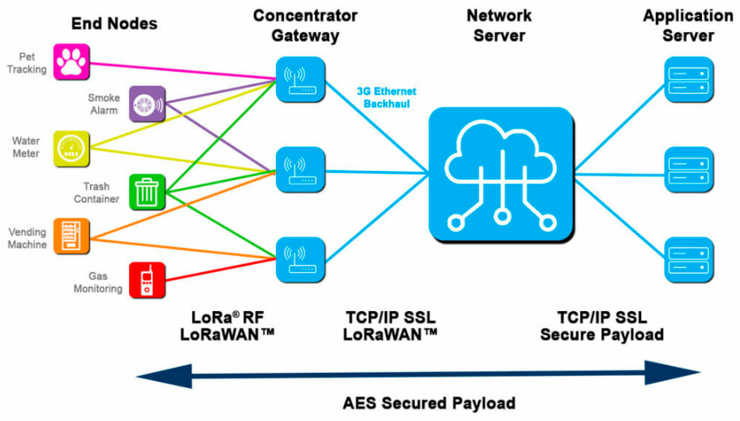
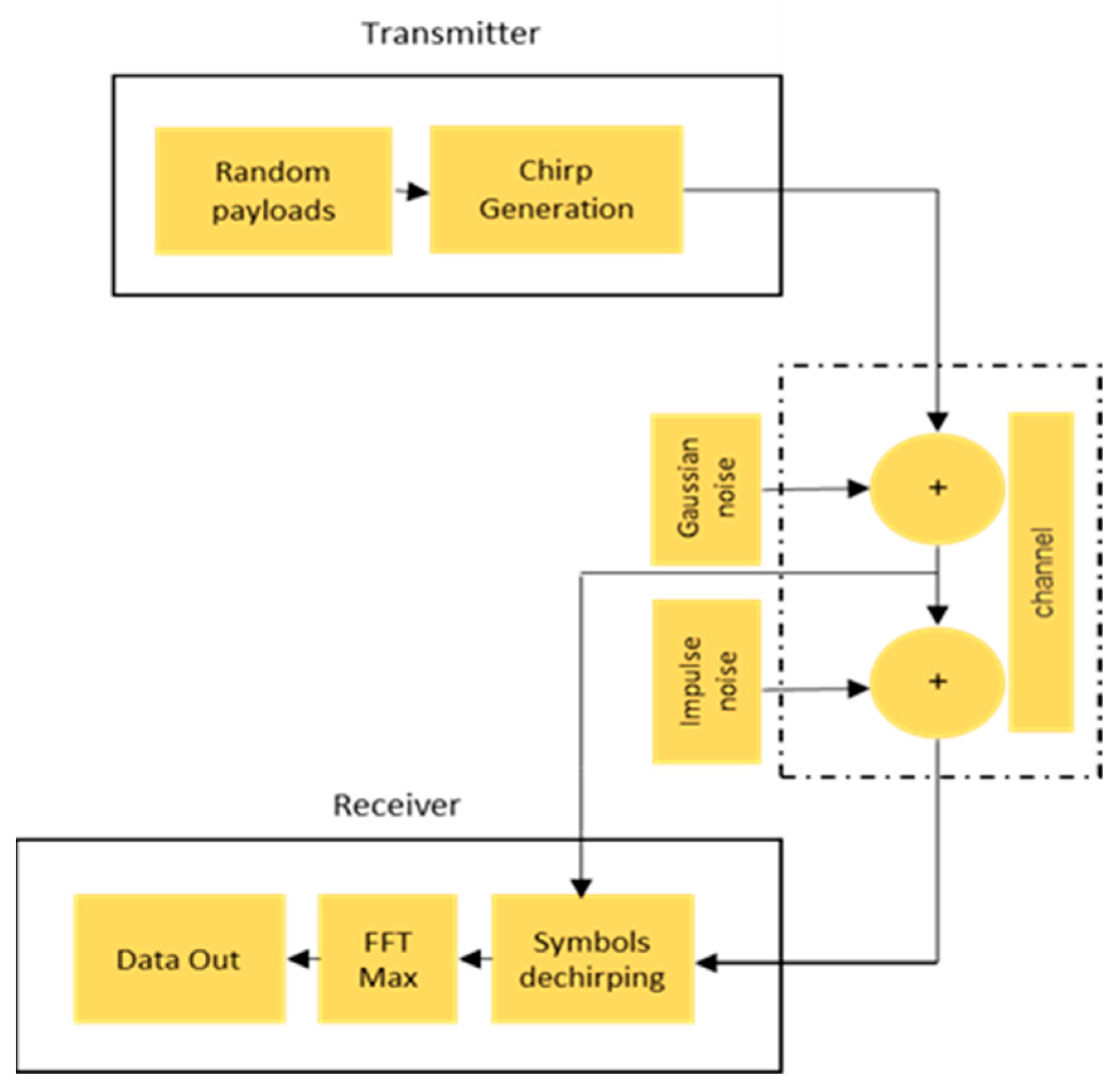
In this section, we will evaluate the performance of CSS modulation adopted by LoRa technology in an industrial environment focusing on the PER. We will essentially consider the “one-to-many” and “many-to-one” architectures specific to the LoRaWAN network, which is based on a star topology [44], as shown in Figure 7. Typically, in the LoRa context, this star configuration allows end devices to exchange with one or more gateways via the LoRa physical layer. These gateways are then connected to a central server using the standard IP protocol. This server is linked to an application server and can also interact downlink with the end devices via the gateway. Figure 8 illustrates the evaluated architecture, primarily consisting of the modulator and demodulator, in addition to an industrial channel.
The various parameters required to define the context of the simulations are presented in Table 2.
Two configurations, LOS and NLOS, were considered. In this work, we have considered that the industrial and AWGN channels are propagation channels with Rician fading in the LOS configuration and Rayleigh fading in the NLOS configuration at a frequency of 868 MHz [22,39].
In all the communication modes considered, the data frames for each transmitter were binary, with different lengths of 32 bits randomly generated. This approach stems from the fact that industrial sensors transmit short packets of data [22].
5.1. One to Many Mode
In OtM communication mode, as shown in Figure 9, a transmitter sends a series of 1000 packets to four non-coherent receivers. Each packet contains data to be transmitted via LoRa. The transmitter initiates transmission by modulating this data into LoRa signals and transmitting them over an AWGN or industrial transmission channel. During propagation, these signals encounter obstacles and other environmental factors that can affect their power and quality in the case of an NLOS configuration. Each receiver detects and receives these signals, then uses LoRa demodulation techniques to extract the transmitted data. Once the data has been successfully demodulated, it can be processed by each receiver independently of the others. This process is repeated for each packet until all 1000 packets have been transmitted and received by all four LoRa receivers.
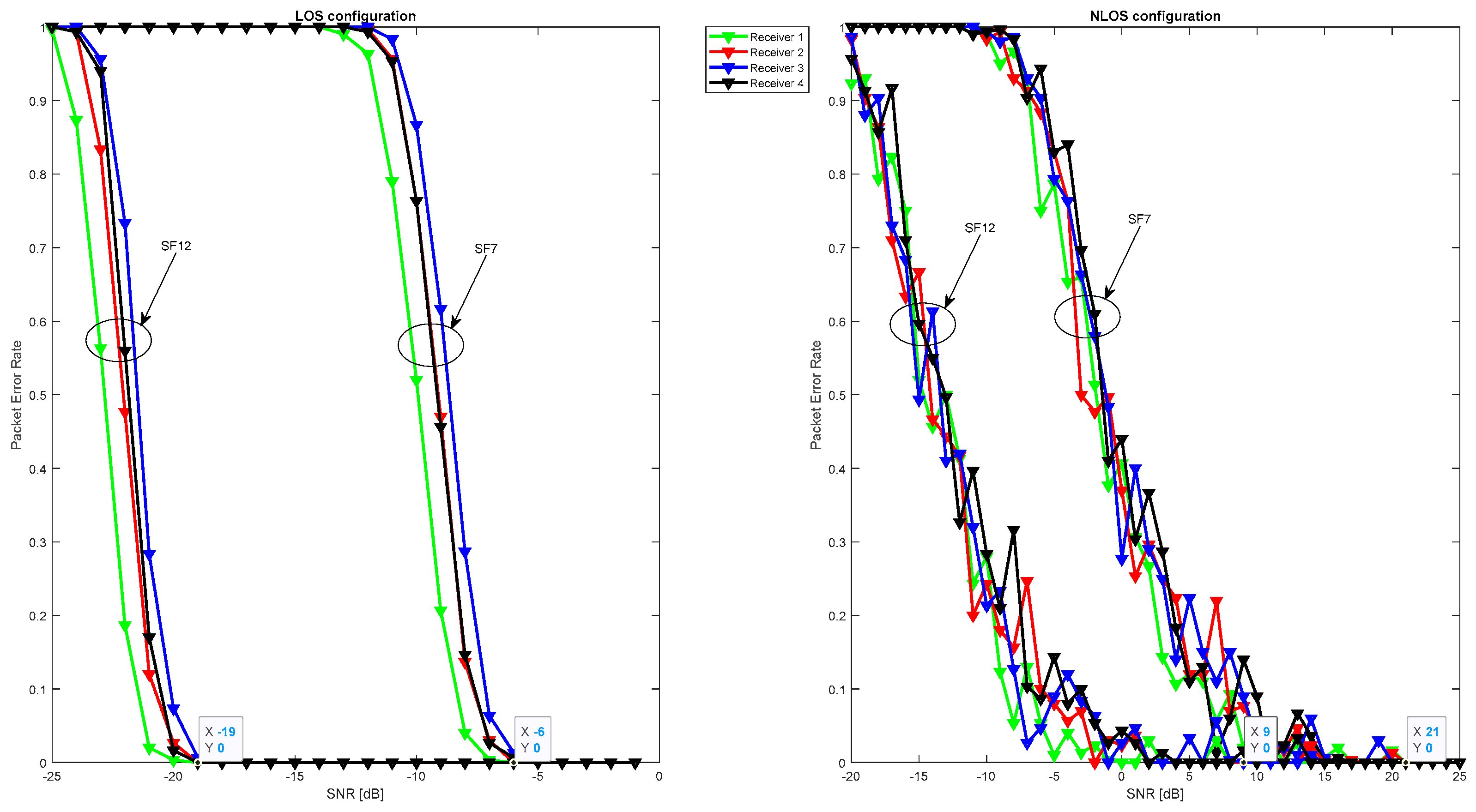
Figure 10 illustrates that signal quality is disturbed in terms of PER due to Gaussian noise in the LOS configuration in addition to the fading effect in the NLOS configuration. However, in the LOS configuration, the signal remains detectable, and packets are received correctly for negative SNR values ranging from −19 dB to −6 dB for spreading factors 12 and 7, respectively. In the NLOS configuration, the signal undergoes strong attenuation, resulting in a gain loss of over 28 dB in SNR, which means that packets are only received correctly for SNR values ranging from 9 up to 21 dB for spreading factors 12 and 7, respectively.
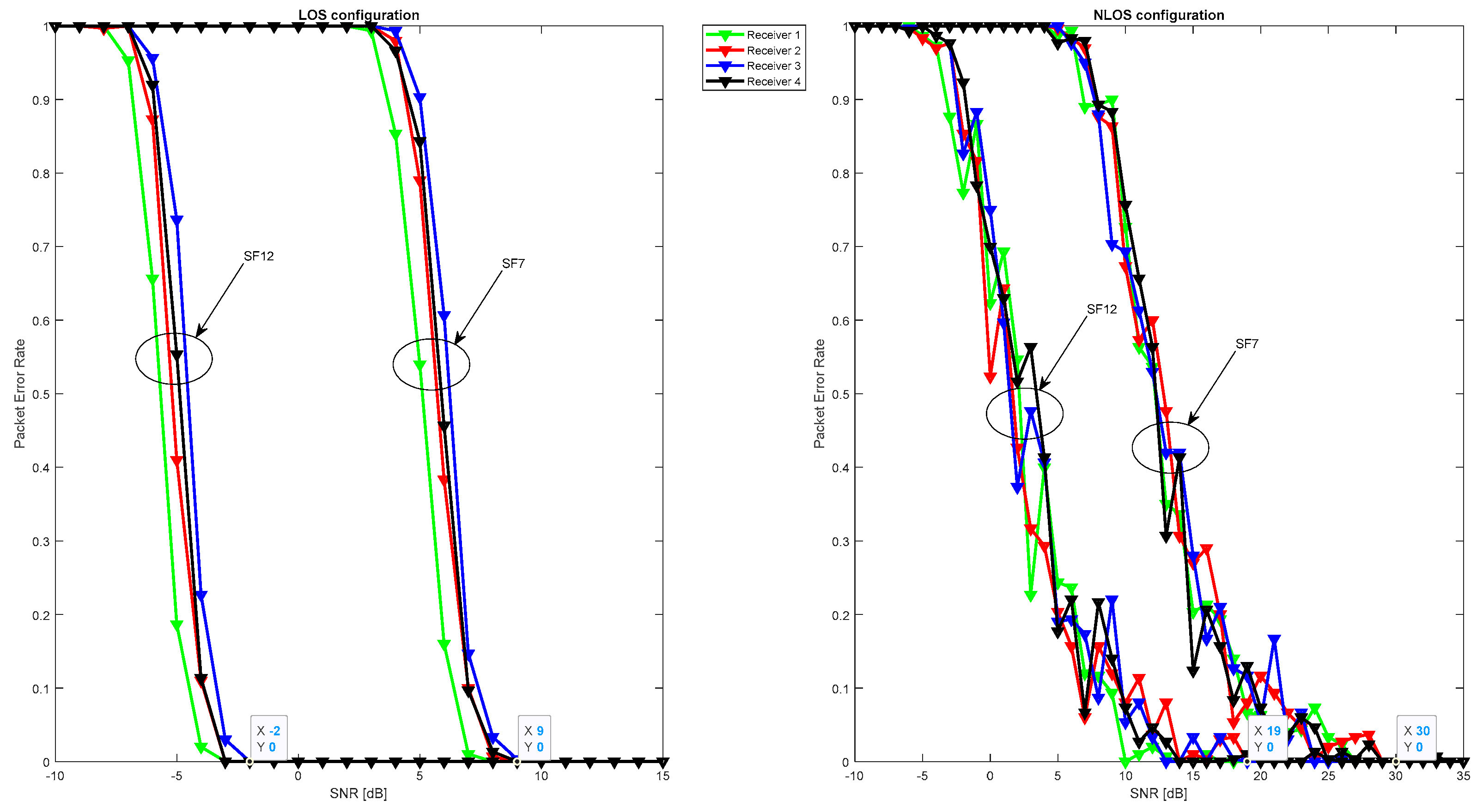
In Figure 11, by adding industrial noise composed of Gaussian noise and impulse noise, the packet error rate was measured. Unlike Gaussian noise, industrial noise is highly disruptive to OtM communication in both LOS and NLOS configurations, resulting in rapid convergence of the communication architecture and reduced performance in terms of packet error rate for the spreading factors considered. However, packets are correctly detected with SNR equal to −2 dB and 9 dB for spreading factors 12 and 7, respectively, in the LOS configuration. Packets are received without error for SNR exceeding 19 and 30 dB in the NLOS configuration for the same spreading factors.
5.2. Many to One Mode
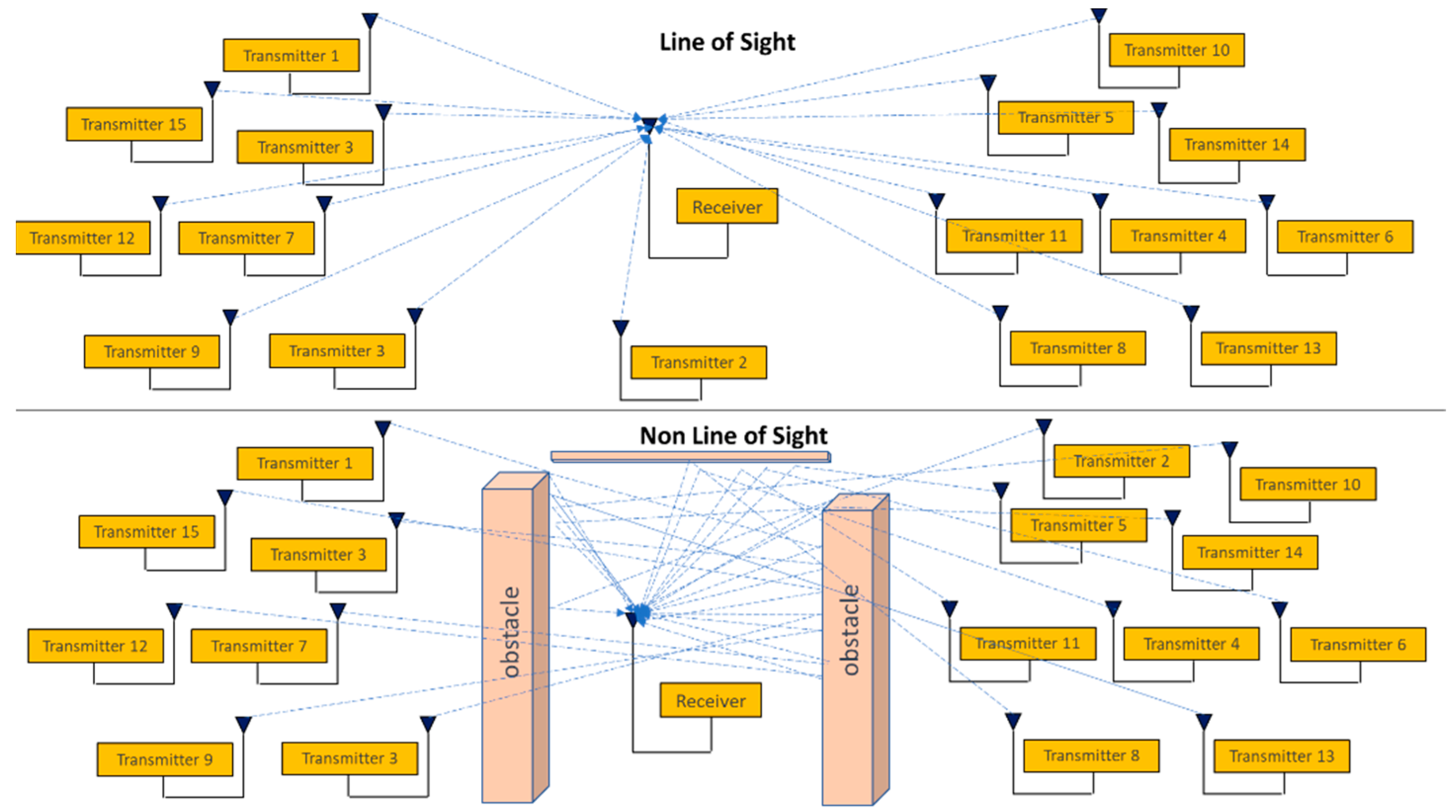
Figure 12 shows the MtO communication mode, where sixteen LoRa transmitters are responsible for sending 1000 packets each to a single LoRa non-coherent receiver. This communication takes place in the same configurations as OtM: LOS and NLOS. At the start of the sending process, each transmitter modulates the data into LoRa signals and transmits them in an AWGN or Industrial transmission channel to the receiver. Since there are no physical obstacles in the LOS configuration, LoRa signals propagate easily from each transmitter to the receiver. In contrast, due to obstacles in the NLOS configuration, some signals may be attenuated, weakened, or distorted. The receiver receives the available signals and stores them temporarily in a buffer to synchronize them, then demodulates and processes them independently until the last packet is sent.
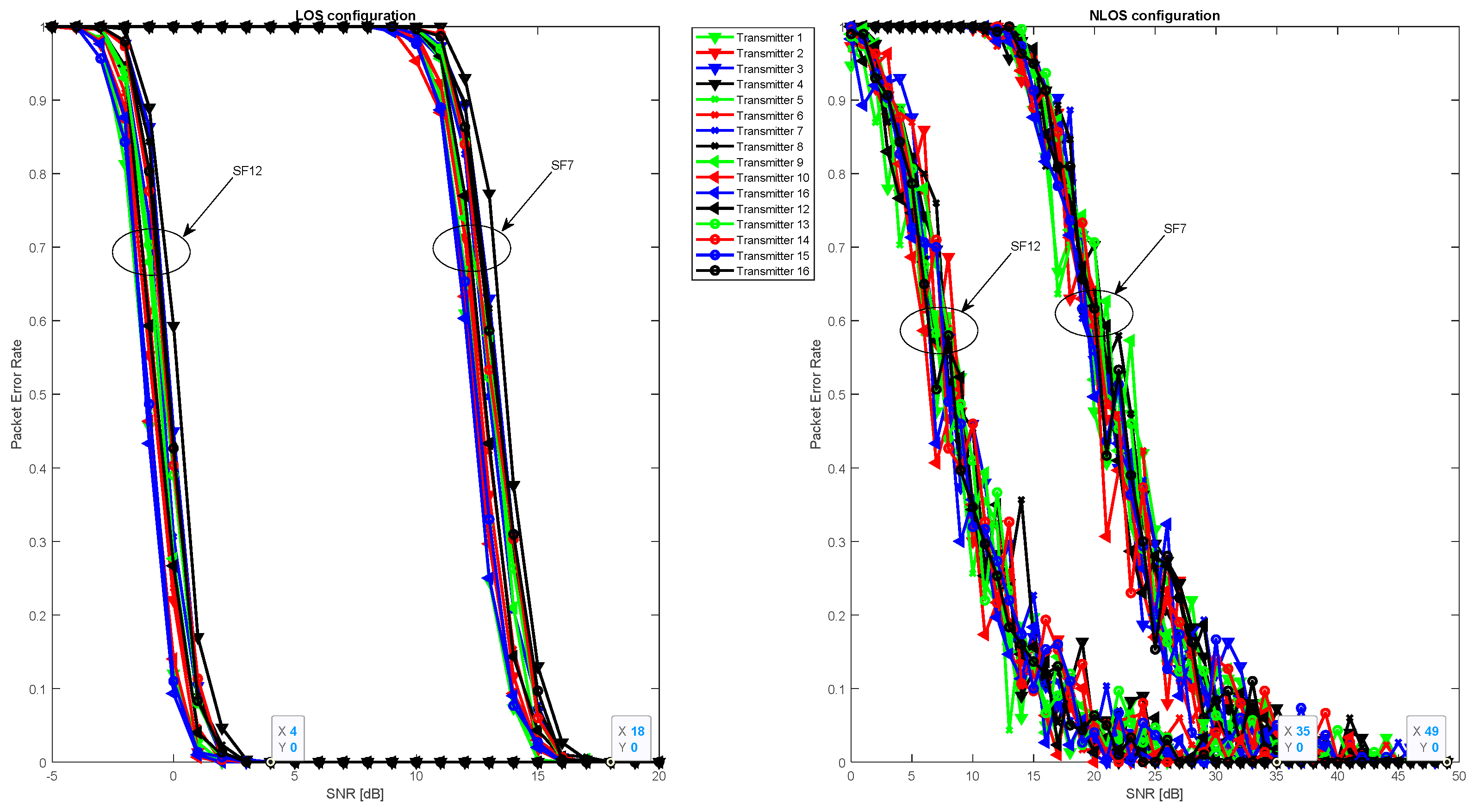
In the MtO communication mode, the signal is detected for all transmitters, as shown in Figure 13 and Figure 14. However, performance in terms of packet error rate is reduced in all configurations considered as shown in Figure 13. This is due to AWGN noise in addition to the effect of multipath, which causes interference between signals from different transmitters. The channel effect is more pronounced in the NLOS configuration, where signals encounter obstacles in addition to AWGN noise, resulting in reflections, diffractions, and dispersions of the signals. As a result, several components of the same signal reach the receiver with different delays and powers.
Performance in terms of PER is greatly reduced in the case of industrial noise in both the LOS and NLOS configurations. However, this architecture can correctly receive packets from signal-to-noise ratios of 4 and 18 dB for SF12 and SF7, respectively, in the LOS configuration and from 35 and 49 dB for the same spreading factors in the NLOS configuration, as shown in Figure 14.
The simulations in this section highlighted a significant degradation in the PER performance of LoRa technology in an industrial environment. This degradation can be problematic, particularly when the data being transmitted is critical. The consequences can include transmission errors, increased latency, or total packet loss. In such situations, the integration of error correction techniques is essential. Forward error correction, as represented by the Hamming code, offers one approach to remedying such errors. This topic will be explored in greater depth in the next section.
6. LoRa Performance: Using Error Correction and Filtering
Following our performance evaluation of LoRa, focusing on PER with CSS modulation, we will explore this further in this section. We will introduce complementary techniques, in particular the Hamming correction code and the IIR and FIR filters, to enrich our understanding of performance dynamics. Our aim is to identify possible improvements or variations in LoRa’s PER by incorporating these elements.
6.1. LoRa with Forward Error Correction and Filtering
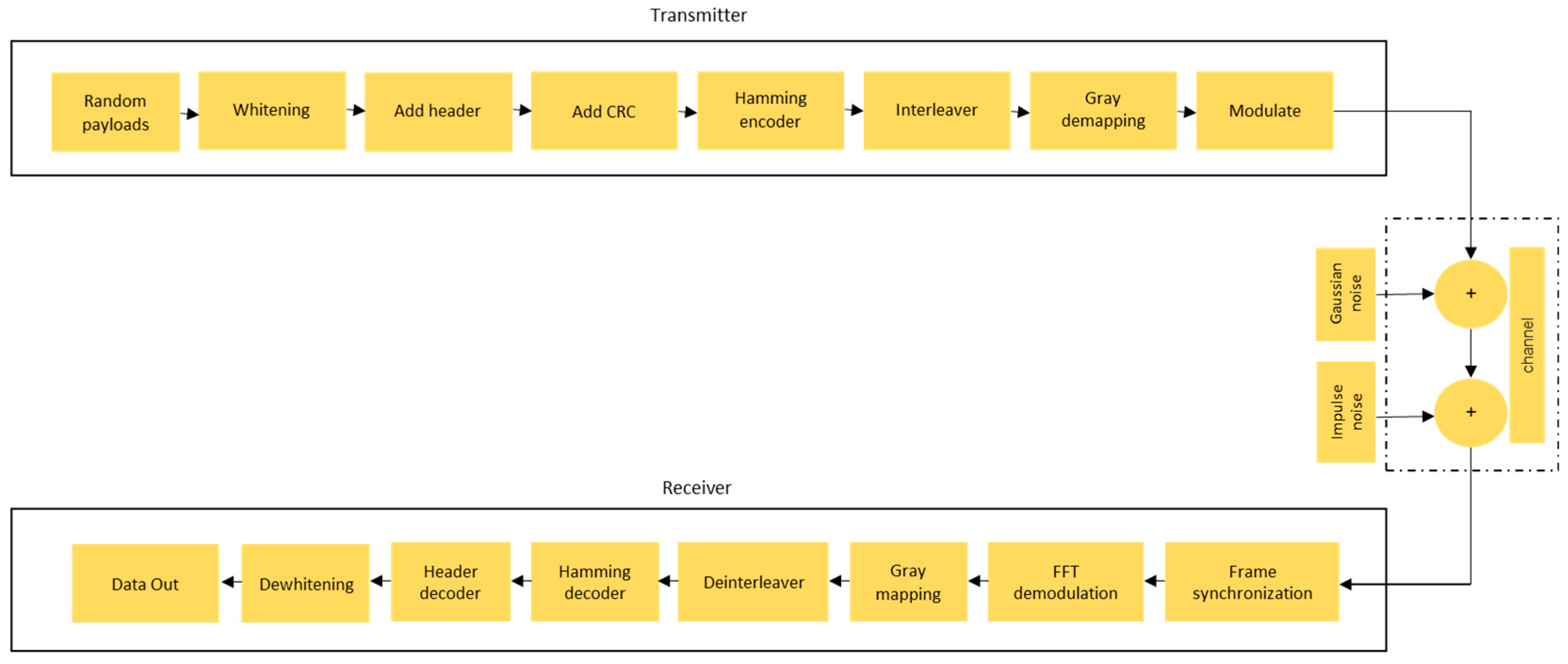
To enhance the performance of LoRa technology, the transmitter and receiver perform additional processing in addition to modulation and demodulation, as shown in Figure 15. The transmitter effects whitening, Hamming encoding, interleaving, and gray mapping before chirp modulation. The receiver effects Gray demapping, deinterleaving, Hamming decoding, and dewhitening.
Prior to modulation, both the header and payload pass through a series of steps to be encoded. Firstly, the payload is whitened by adding a known sequence depending on the payload’s coding rate parameter [36,45]. Secondly, the resulting payload and header are encoded using the Hamming Error-correcting code. The Hamming codes used by LoRa are of the form (k, n), with k equal to 4 and n taking the values {5, 6, 7, 8}, where k denotes the length of the data words and n the length of the code words [36,46]. The resulting payload can be encoded using any of the Hamming code combinations, whereas the header, since it contains crucial payload information, can only be encoded using the two Hamming combinations (4,7) and (4,8). This is because Hamming codes (4,5) and (4,6) can only detect errors, whereas Hamming codes (4,7) and (4,8) allow the detection and correction of one bit error per code word [36]. Thirdly, the payload and header are interleaved. This is done by transposing k-code words and shifting their digits to the left by r mod SF, where r is the line number. The header and payload are interleaved by (SF − 2 × 8) and (SF × 4 + CR), respectively. Finally, to reduce adjacent-bit errors, gray coding is applied to the interleaved symbols [36].
6.1.1. One to Many Mode
Analysis of Figure 16 highlights the performance of different coding rates in OtM mode within an industrial channel equipped with four receivers. Channel coding gain fluctuation is influenced by the coding rate used, with the 4/8 rate standing out as clearly superior to the 4/5 rate in all the configurations considered. The LOS configuration is particularly revealing: even with a signal-to-noise ratio as low as −10 dB, packets are received without error with a spreading factor of 12. When this factor is 7, this result is reproduced with a signal-to-noise ratio of 1 dB. The contrast is striking between the gains associated with the two coding rates in question in this configuration: over 7 dB for the 4/8 rate versus less than 3 dB for the 4/5 rate. This is because the 4/5 coding rate only enables error detection, whereas 4/8 also enables error correction [36]. This observation highlights the importance of choosing the right coding rate, especially in industrial contexts where transmission reliability is paramount.
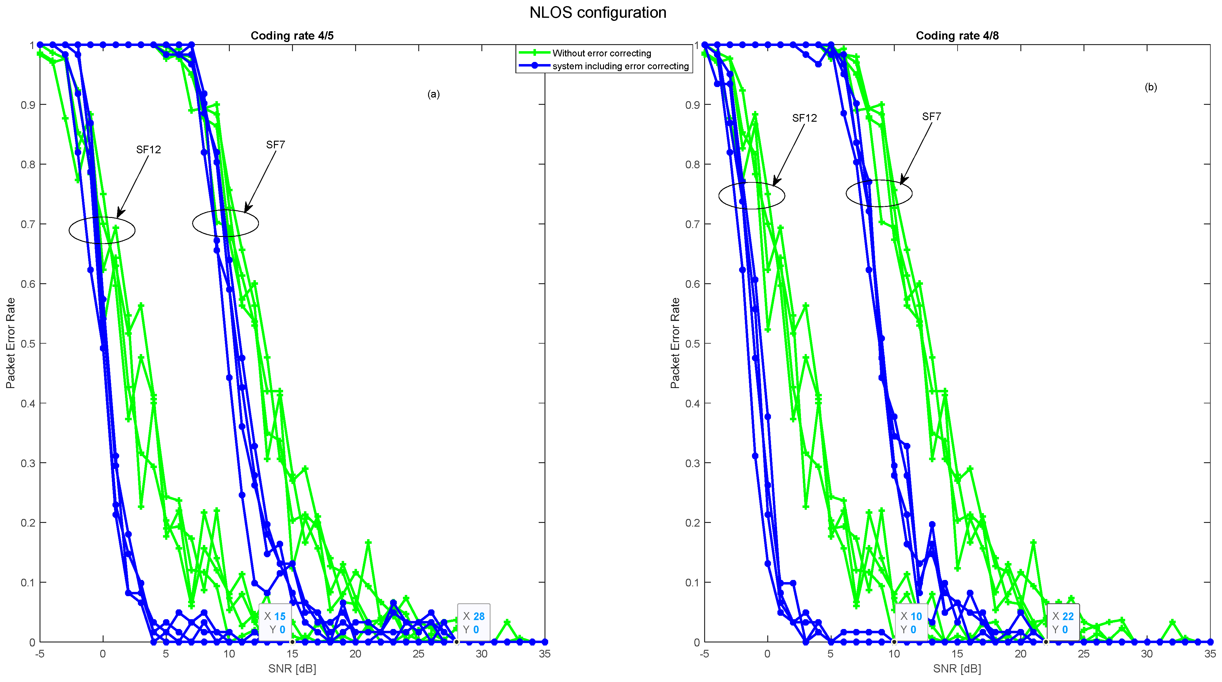
Furthermore, the detailed analysis in Figure 17 highlights the performance of coding rates in the NLOS (non-line-Of-Sight) configuration. This configuration, combined with the inherent challenges of potential obstacles interfering with signal transmission, calls for judicious technical choices. The 4/8 code rate is clearly the optimal choice, offering a robust gain of over 7 dB for spreading factors 12 and 7. On the other hand, the 4/5 coding rate, although a high-performance choice, offers a significantly lower gain, not exceeding 2 dB for the same factors. These observations are reinforced by an examination of the signal-to-noise ratios. For rate 4/5, packets are correctly received with ratios of 15 dB and 28 dB for spreading factors of 7 and 12, respectively. However, rate 4/8 still stands out with ratios of 10 dB and 22 dB, guaranteeing flawless transmission for these same spreading factors. Thus, Figure 17 clearly illustrates the advantage of the 4/8 rate, particularly under NLOS conditions, offering essential insights for anyone seeking to optimize data transmission in complex environments.
6.1.2. Many to One Mode
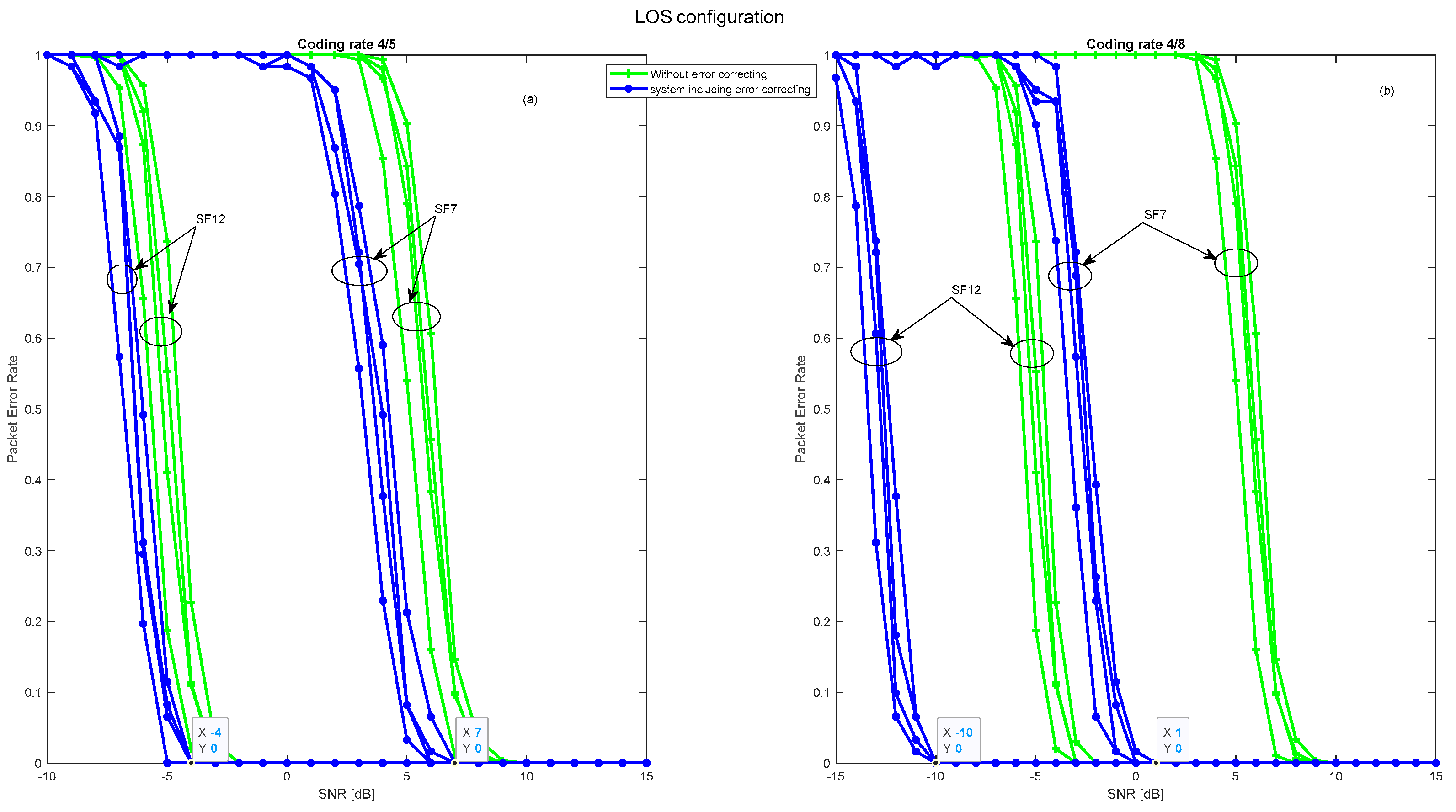
In MtO mode, characterized by the presence of sixteen transmitters communicating with a single receiver, Figure 18 highlights the influence of the coding rate on transmission performance. In the LOS configuration, the 4/5 coding rate demonstrates high accuracy, detecting all signals without error, despite the multitude of transmitters. Signal-to-noise ratios of 4 dB and 18 dB, combined with spreading factors of 12 and 7, attest to this performance. However, the gain in terms of SNR with this ratio is limited to less than 2 dB. On the other hand, the 4/8 code rate, in addition to its detection capability, actively corrects errors. This translates into exceptional efficiency, evident in signal-to-noise ratios of −6 dB and 8 dB for the same spreading factors. With an impressive SNR gain of 9 dB, the 4/8 rate is the optimal choice, especially in this dense transmission mode. In summary, Figure 18 underlines that, faced with the challenges of the MtO mode and its sixteen transmitters, the 4/8 rate appears to be the best option for guaranteeing optimal transmission, particularly in terms of signal-to-noise ratio.
A detailed exploration of Figure 19 sheds relevant light on the performance of coding rates under NLOS conditions. At first glance, it might appear that the 4/5 and 4/8 coding rates behave comparably. However, closer observation reveals significant differences between the two. While the 4/5 code rate offers reliable transmission, with perfect packet reception at signal-to-noise ratios of 32 dB and 46 dB, the 4/8 code rate excels even further. It guarantees flawless reception at significantly lower levels, precisely 23 dB and 40 dB, for spreading factors of 12 and 7, respectively. This 10 dB gain between the two coding rates is not insignificant and testifies to the superior robustness of the 4/8 rate. In other words, in NLOS transmission environments, where conditions can be unpredictable and obstacles numerous, the 4/8 coding rate clearly stands out as the best option, guaranteeing not only efficient data transmission but also a reduced margin of error, which is essential for ensuring continuity and quality of communication.
In this subsection, the results show a significant improvement in LoRa’s PER performance thanks to the integration of forward error correction. However, to further optimize this performance, we envisage adopting the IIR and FIR filters. This technical choice and the expected benefits will be the focus of discussion in the next subsection.
6.2. LoRa with Forward Error Correction and Filtering
In addition to incorporating forward error correction, IIR and FIR filters are added immediately after the removal of the signal carrier. This integration aims to improve the performance of LoRa technology in industrial settings. These filters are designed using the Butterworth approximation method, which enables specific filter characteristics to be obtained to meet design requirements. First, the specifications of these filters are determined, including parameters such as normalized cutoff frequency, sampling frequency, and optimal filter order, as shown in Table 3.
The optimum order of the two filters is obtained by using a loop to test different IIR filter orders (up to 30) and calculating the error produced between the filtered signal and the clean signal (at the transmitter) for each order. The optimum order is then determined by selecting the one with the lowest error value.
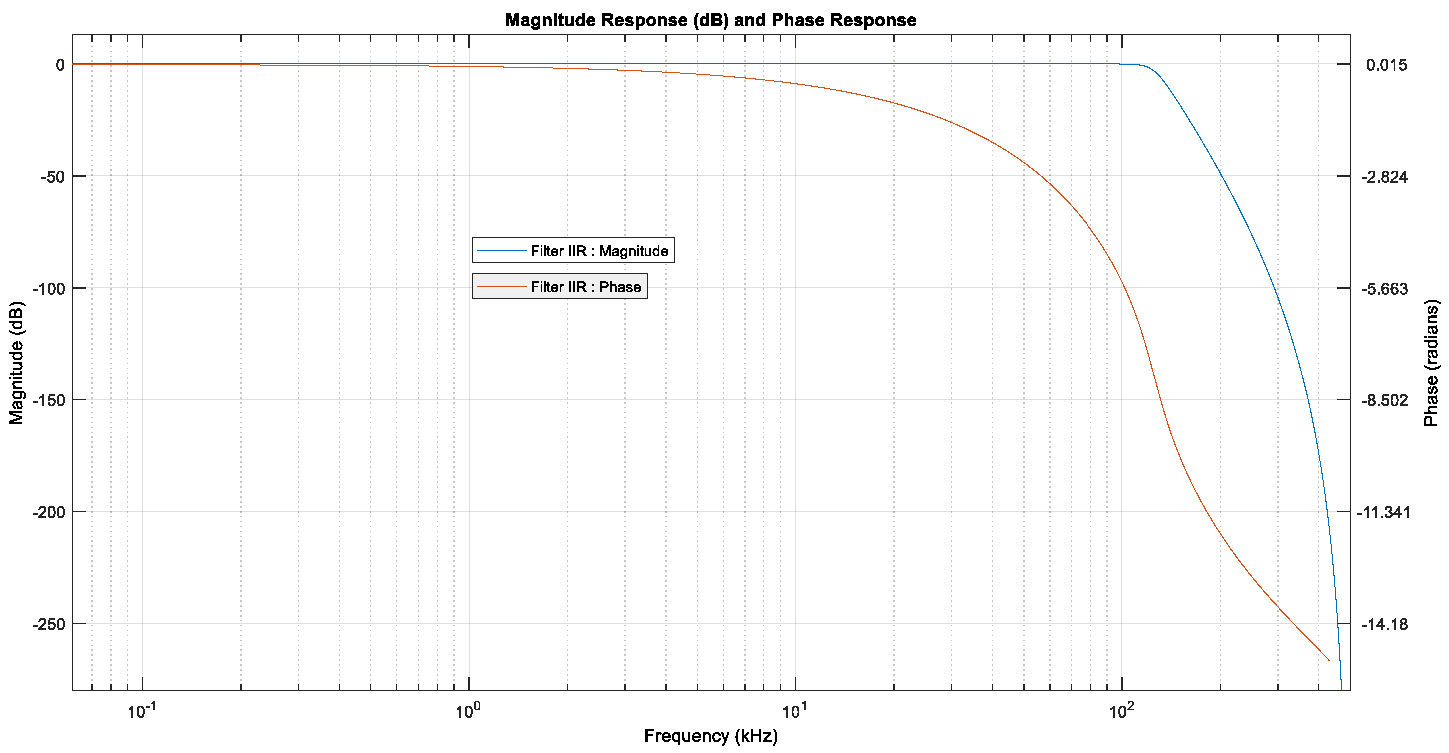
The FIR and IIR filters designed are both characterized by their stability. The FIR filter has an optimum order of 18 and uses 19 coefficients, while the IIR filter has an order of 10 and uses 21 coefficients. A notable distinction between the two is the nature of the phase: the FIR filter has a linear phase, while the IIR filter has a non-linear phase, meaning that the different frequencies of the input signal are shifted temporally in a constant manner for the FIR filter, while a frequency-dependent temporal delay occurs for the IIR filter as shown in Figure 20 and Figure 21. These characteristics must be considered when selecting the appropriate filter for specific application requirements, as they influence filtering accuracy and the time delay of the various input signal frequencies.
The 4/5 coding rate does not produce a significant gain in all the above configurations, which is why the simulations of adding these filters are carried out under the same conditions, exposing only the results obtained for this coding rate.
6.2.1. One to Many Mode
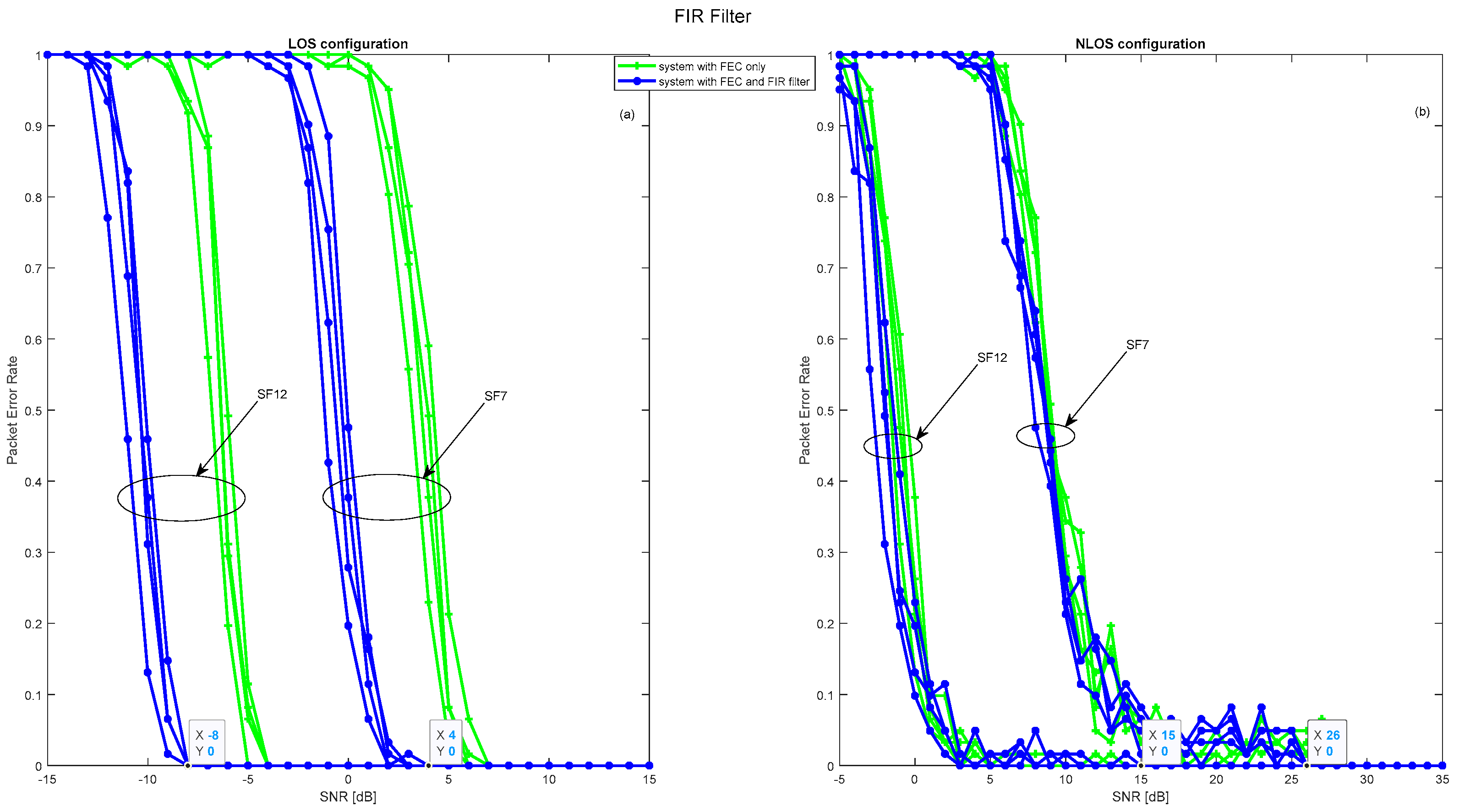
The introduction of IIR and FIR filters to receivers operating in OtM mode is a crucial step in enhancing LoRa’s PER performance, whatever the configurations involved. This improvement, however, manifests itself differently depending on the type of filter and its order. The details of these dynamics are illustrated in Figure 22 and Figure 23, which highlight the optimum performance associated with each filter order. In a LOS configuration, the positive impact of these filters is indisputable. Both the IIR and FIR filters deliver an appreciable 4 dB gain in signal-to-noise ratio. This translates into perfect packet reception, with values of −7 dB and 4 dB for spreading factors 7 and 12, respectively. In NLOS mode, on the other hand, the benefits, while present, are slightly attenuated due to fading phenomena and disturbances such as industrial noise. Despite these challenges, a gain of 2 dB is noted, enabling the correct reception of 90% of packets with values of 2 dB and 12 dB for the two spreading factors mentioned. Overall, the incorporation of IIR and FIR filters proves to be a strategic initiative to improve the reliability of LoRa transmission in OtM mode, although the degree of improvement intrinsically depends on the transmission context.
6.2.2. Many to One Mode
The judicious integration of an IIR or FIR filter within a single receiver, designed to handle transmissions from sixteen transmitters in MtO mode, marked a decisive step forward in communication performance. By filtering out noise, these filters have considerably improved transmission, even in a LOS configuration which, although ideally favored, benefits from a substantial gain of 5 dB with these filters, as shown in Figure 24a and Figure 25a. Under these conditions, the packet error rate tends towards zero, especially at signal-to-noise ratios of −1 dB and 12 dB for spreading factors of 12 and 7, respectively. The NLOS configuration reinforces the importance of these filters, as shown in Figure 24b and Figure 25b. Despite the inherent complexity of intercepting signals from sixteen separate transmitters and the challenges associated with this configuration, a gain of over 4 dB is observed, with 90% of packets received without fail at signal-to-noise ratios of 10 dB and 25 dB for the spreading factors mentioned. In summary, these results unequivocally demonstrate the positive impact of receiver-integrated IIR and FIR filters, underscoring their vital role in ensuring flawless communication in a scenario where a single receiver handles signals from sixteen or fewer transmitters.
An analysis of LoRa technology performance, illustrated in Table 4, reveals key trends for OtM (one-to-many) and MtO (many-to-one) communication modes. In an AWGN context, regardless of the mode used, the SF12 spreading factor systematically presents a more advantageous SNR threshold than SF7. However, as we move towards industrial conditions, the SNR threshold for both modes, OtM and MtO, increases, indicating a need for a stronger signal to overcome the environmental noise.
This table highlights the relevance of optimizations using forward error correction, especially under demanding industrial conditions. While the adoption of a 4/5 code rate brings improvements, especially in OtM mode, it’s really the 4/8 code rate that shines through, especially in OtM mode, testifying to its performance in the face of industrial interference.
Introducing filters such as IIR or FIR while maintaining a 4/5 coding rate further enhances SNR threshold performance for both communication modes. In particular, the FIR filter shows a slight superiority over the IIR, especially for the OtM mode.
7. Conclusions and Perspectives
This article presents an evaluation, based on MATLAB simulations, of the performance of LoRa technology in terms of PER in an industrial environment. The industrial channel is modeled as a propagation channel affected by impulsive noise combined with additive white Gaussian noise. In the LOS scenario, received signals follow a statistical Rice distribution, while in the NLOS case they follow a Rayleigh distribution. LoRa technology performs well in terms of PER in an AWGN environment but suffers significant degradation in an industrial environment, particularly in the NLOS configuration for the MtO and OtM communication modes. LoRa performance is enhanced by using the using Forward error correction, and by applying filtering with IIR or FIR filters at reception. The SNR gain varies according to the coding rate used and the configuration studied. By using a 4/8 coding rate, LoRa’s performance is greatly improved, and all packets are received completely without error from an SNR of −10 dB and −1 dB for spreading factors 12 and 7, respectively, with a 10 dB gain in both the LOS and NLOS scenarios for the OtM communication mode. For the MtO mode, all packets are received without error between −6 and 8 for the same spreading factors and on the same channel. By using the IIR or FIR filter, performance is further improved, with an additional gain of 4 dB, particularly for the 4/5 coding rate in all the communication modes considered. In OtM mode, all packets are received correctly at −8 dB and 3 dB for spreading factors 12 and 7, respectively. Similarly, for OtM mode, packet errors are eliminated between −2 dB and 12 dB for the same spreading factors on the same channel. Although the addition of error correction and the application of IIR and FIR filters can significantly enhance the performance of LoRa technology in industrial environments, it is essential to approach this proposal with a balanced view. The use of these solutions could lead to increased complexity, resulting not only in greater resource use but also a potential increase in energy consumption. The efficiency of these filters, while optimal in specific scenarios, may not be universal in the face of the diversity of industrial disturbances. Moreover, the additional latency introduced by these methods could be a hindrance for certain real-time applications. Added to this is the possible increase in the size of transmitted packets, which may influence the useful throughput. Following on from our current research, several promising prospects are emerging. Firstly, it is essential to undertake an in-depth evaluation of the optimal choice between IIR and FIR filters for LoRa technology in specific applications. This investigation will not be limited to the selection of the filter type, but will also extend to the determination of the ideal coding rate, taking into account power consumption and resource constraints. Furthermore, in view of the challenges posed by communication in industrial environments, another promising direction would be to consider extending the “Many-to-Many” operating mode of LoRa technology. This mode, with its inherently flexible, collaborative and resilient nature, could revolutionize the efficiency, coordination and reliability of data exchanges in these environments. These perspectives are not only in line with our current work, but also highlight crucial steps towards exploiting the full potential of LoRa technology.
Author Contributions
Writing—original draft preparation L.A.; Validation-Supervision M.T.; Supervision H.H. All authors have read and agreed to the published version of the manuscript.
Funding
This research work was funded by the Moroccan School of Engineering Sciences EMSI Casablanca.
Data Availability Statement
The data presented in this study are available on request from the corresponding author.
Conflicts of Interest
The authors declare no conflict of interest.
Abbreviations
| LoRa | long range |
| IIoT | Industrial Internet of Things |
| LPWAN | Low-power wide area network |
| PER | Packet Error Rate |
| FEC | Forward error correction |
| IIR | Infinite Impulse Response |
| FIR | Finite Impulse Response |
| LOS | Line of Sight |
| NLOS | Non-Line of Sight |
| SF | Spreading Factor |
| OtM | one-to-many |
| MtO | many to one |
References
- Lucas-Estañ, M.; Sepulcre, M.; Raptis, T.; Passarella, A.; Conti, M. Emerging Trends in Hybrid Wireless Communication and Data Management for the Industry 4.0. Electronics 2018, 7, 400. [Google Scholar] [CrossRef]
- Hazra, A.; Adhikari, M.; Amgoth, T.; Srirama, S.N. A Comprehensive Survey on Interoperability for IIoT: Taxonomy, Standards, and Future Directions. ACM Comput. Surv. 2023, 55, 1–35. [Google Scholar] [CrossRef]
- Ab, E. Cellular Networks for Massive IoT—Enabling Low Power Wide Area Applications. 2020. Available online: https://www.gsma.com/iot/resources/cellular-networks-for-massive-iot-enabling-low-power-wide-area-applications/ (accessed on 5 June 2023).
- Nurelmadina, N.; Hasan, M.K.; Memon, I.; Saeed, R.A.; Zainol Ariffin, K.A.; Ali, E.S.; Mokhtar, R.A.; Islam, S.; Hossain, E.; Hassan, M.A. A Systematic Review on Cognitive Radio in Low Power Wide Area Network for Industrial IoT Applications. Sustainability 2021, 13, 338. [Google Scholar] [CrossRef]
- Leonardi, L.; Battaglia, F.; Lo Bello, L. RT-LoRa: A Medium Access Strategy to Support Real-Time Flows Over LoRa-Based Networks for Industrial IoT Applications. IEEE Internet Things J. 2019, 6, 10812–10823. [Google Scholar] [CrossRef]
- Fahmida, S.; Modekurthy, V.P.; Ismail, D.; Jain, A.; Saifullah, A. Real-Time Communication over LoRa Networks. In Proceedings of the 2022 IEEE/ACM Seventh International Conference on Internet-of-Things Design and Implementation (IoTDI), Milano, Italy, 4–6 May 2022; pp. 14–27. [Google Scholar] [CrossRef]
- Sandoval, R.M.; Garcia-Sanchez, A.-J.; Garcia-Haro, J. Performance optimization of LoRa nodes for the future smart city/industry. J. Wirel. Commun. Netw. 2019, 2019, 200. [Google Scholar] [CrossRef]
- Paredes-Parra, J.M.; García-Sánchez, A.J.; Mateo-Aroca, A.; Molina-Garcia, A. An Alternative Internet-of-Things Solution Based on LoRa for PV Power Plants: Data Monitoring and Management. Energies 2019, 12, 881. [Google Scholar] [CrossRef]
- Amelia, F.; Ramadhani, M.F. LoRa-Based Asset Tracking System with Data Encryption Using AES-256 Algorithm. In Proceedings of the 2022 International Conference on Radar, Antenna, Microwave, Electronics, and Telecommunications (ICRAMET), Bandung, Indonesia, 6–7 December 2022; pp. 194–199. [Google Scholar] [CrossRef]
- Mataloto, B.; Ferreira, J.C.; Cruz, N. LoBEMS—IoT for Building and Energy Management Systems. Electronics 2019, 8, 763. [Google Scholar] [CrossRef]
- García, S.; Larios, D.F.; Barbancho, J.; Personal, E.; Mora-Merchán, J.M.; León, C. Heterogeneous LoRa-Based Wireless Multimedia Sensor Network Multiprocessor Platform for Environmental Monitoring. Sensors 2019, 19, 3446. [Google Scholar] [CrossRef]
- Muduli, A.; Kanakaraja, P.; Ravi Chandrika, M.; Sanjana, Y.; Sharukh, S. Industrial Environment Monitoring System Using LoRa. In Proceedings of the 2nd International Conference on Recent Trends in Machine Learning, IoT, Smart Cities and Applications; Gunjan, V.K., Zurada, J.M., Eds.; Lecture Notes in Networks and Systems; Springer Nature: Singapore, 2022; Volume 237, pp. 665–678. ISBN 9789811664069. [Google Scholar] [CrossRef]
- Yao, F.; Ding, Y.; Hong, S.; Yang, S.-H. A Survey on Evolved LoRa-Based Communication Technologies for Emerging Internet of Things Applications. Int. J. Netw. Dyn. Intell. 2022, 1, 4–19. [Google Scholar] [CrossRef]
- Tessaro, L.; Raffaldi, C.; Rossi, M.; Brunelli, D. LoRa Performance in Short Range Industrial Applications. In Proceedings of the 2018 International Symposium on Power Electronics, Electrical Drives, Automation and Motion (SPEEDAM), Amalfi, Italy, 20–22 June 2018; pp. 1089–1094. [Google Scholar] [CrossRef]
- Sanchez-Iborra, R.; Sanchez-Gomez, J.; Ballesta-Viñas, J.; Cano, M.-D.; Skarmeta, A. Performance Evaluation of LoRa Considering Scenario Conditions. Sensors 2018, 18, 772. [Google Scholar] [CrossRef]
- Renzone, G.D.; Landi, E.; Mugnaini, M.; Parri, L.; Peruzzi, G.; Pozzebon, A. Assessment of LoRaWAN Transmission Systems Under Temperature and Humidity, Gas, and Vibration Aging Effects within IIoT Contexts. IEEE Trans. Instrum. Meas. 2022, 71, 5500311. [Google Scholar] [CrossRef]
- Branch, P.; Cricenti, T. A LoRa Based Wireless Relay Network for Actuator Data. In Proceedings of the 2020 International Conference on Information Networking (ICOIN), Barcelona, Spain, 7–10 January 2020; pp. 190–195. [Google Scholar] [CrossRef]
- Petajajarvi, J.; Mikhaylov, K.; Roivainen, A.; Hanninen, T.; Pettissalo, M. On the coverage of LPWANs: Range evaluation and channel attenuation model for LoRa technology. In Proceedings of the 2015 14th International Conference on ITS Telecommunications (ITST), Copenhagen, Denmark, 2–4 December 2015; pp. 55–59. [Google Scholar] [CrossRef]
- Kanakaraja, P.; Sairamnadipalli, L.S.P. Industrial parameters monitoring with lora technology in next generation wireless communications. Turk. J. Physiother. Rehabil. 2021, 32, 805–815. [Google Scholar]
- Zhu, J.; Zou, Y.; Zheng, B. Physical-Layer Security and Reliability Challenges for Industrial Wireless Sensor Networks. IEEE Access 2017, 5, 5313–5320. [Google Scholar] [CrossRef]
- Chiwewe, T.M.; Mbuya, C.F.; Hancke, G.P. Using Cognitive Radio for Interference-Resistant Industrial Wireless Sensor Networks: An Overview. IEEE Trans. Ind. Inf. 2015, 11, 1466–1481. [Google Scholar] [CrossRef]
- Saadaoui, S.; Tabaa, M.; Monteiro, F.; Chehaitly, M.; Dandache, A. Discrete Wavelet Packet Transform-Based Industrial Digital Wireless Communication Systems. Information 2019, 10, 104. [Google Scholar] [CrossRef]
- Bahri, N.; Saadaoui, S.; Tabaa, M.; Sadik, M.; Medromi, H. Study of LoRaWAN Performance Under a Noisy Industrial Channel. In Advances on Smart and Soft Computing; Saeed, F., Al-Hadhrami, T., Mohammed, E., Al-Sarem, M., Eds.; Advances in Intelligent Systems and Computing; Springer: Singapore, 2022; Volume 1399, pp. 465–475. ISBN 9789811655586. [Google Scholar] [CrossRef]
- Emmanuel, L.; Farjow, W.; Fernando, X. LoRa Wireless Link Performance in Multipath Underground Mines. In Proceedings of the 2019 International Conference on Innovation and Intelligence for Informatics, Computing, and Technologies (3ICT), Sakhier, Bahrain, 22–23 September 2019; pp. 1–4. [Google Scholar] [CrossRef]
- Angrisani, L.; Arpaia, P.; Bonavolonta, F.; Conti, M.; Liccardo, A. LoRa protocol performance assessment in critical noise conditions. In Proceedings of the 2017 IEEE 3rd International Forum on Research and Technologies for Society and Industry (RTSI), Modena, Italy, 11–13 September 2017; pp. 1–5. [Google Scholar] [CrossRef]
- Courjault, J.; Vrigneau, B.; Berder, O.; Bhatnagar, M.R. How robust is a LoRa communication against impulsive noise? In Proceedings of the 2020 IEEE 31st Annual International Symposium on Personal, Indoor and Mobile Radio Communications, London, UK, 31 August–3 September 2020; pp. 1–6. [Google Scholar] [CrossRef]
- Magrin, D.; Capuzzo, M.; Zanella, A.; Vangelista, L.; Zorzi, M. Performance Analysis of LoRaWAN in Industrial Scenarios. IEEE Trans. Ind. Inf. 2021, 17, 6241–6250. [Google Scholar] [CrossRef]
- Inagaki, K.; Narieda, S.; Fujii, T.; Umebayashi, K.; Naruse, H. Measurements of LoRa Propagation in Harsh Environment: Numerous NLOS Areas and Ill-Conditioned LoRa Gateway. In Proceedings of the 2019 IEEE 90th Vehicular Technology Conference (VTC2019-Fall), Honolulu, HI, USA, 22–25 September 2019; pp. 1–5. [Google Scholar] [CrossRef]
- Haxhibeqiri, J.; Karaagac, A.; Van den Abeele, F.; Joseph, W.; Moerman, I.; Hoebeke, J. LoRa indoor coverage and performance in an industrial environment: Case study. In Proceedings of the 2017 22nd IEEE International Conference on Emerging Technologies and Factory Automation (ETFA), Limassol, Cyprus, 12–15 September 2017; pp. 1–8. [Google Scholar] [CrossRef]
- Khutsoane, O.; Isong, B.; Gasela, N.; Abu-Mahfouz, A.M. WaterGrid-Sense: A LoRa-Based Sensor Node for Industrial IoT Applications. IEEE Sens. J. 2020, 20, 2722–2729. [Google Scholar] [CrossRef]
- Hoang, Q.L.; Jung, W.-S.; Yoon, T.; Yoo, D.; Oh, H. A Real-Time LoRa Protocol for Industrial Monitoring and Control Systems. IEEE Access 2020, 8, 44727–44738. [Google Scholar] [CrossRef]
- Tran, H.P.; Jung, W.-S.; Yoon, T.; Yoo, D.-S.; Oh, H. A Two-Hop Real-Time LoRa Protocol for Industrial Monitoring and Control Systems. IEEE Access 2020, 8, 126239–126252. [Google Scholar] [CrossRef]
- Lentz, J.; Hill, S.; Schott, B.; Bal, M.; Abrishambaf, R. Industrial Monitoring and Troubleshooting Based on LoRa Communication Technology. In Proceedings of the IECON 2018-44th Annual Conference of the IEEE Industrial Electronics Society, Washington, DC, USA, 21–23 October 2018; pp. 3852–3857. [Google Scholar] [CrossRef]
- Cameron, C.; Naeem, W.; Li, K. Functional Qos Metric For Lorawan Applications In Challenging Industrial Environment. In Proceedings of the 2020 16th IEEE International Conference on Factory Communication Systems (WFCS), Porto, Portugal, 27–29 April 2020; pp. 1–6. [Google Scholar] [CrossRef]
- Soto-Vergel, A.; Arismendy, L.; Bornacelli-Durán, R.; Cardenas, C.; Montero-Arévalo, B.; Rivera, E.; Calle, M.; Candelo-Becerra, J.E. LoRa Performance in Industrial Environments: Analysis of Different ADR Algorithms. IEEE Trans. Ind. Inf. 2023, 19, 10501–10511. [Google Scholar] [CrossRef]
- Al Homssi, B.; Dakic, K.; Maselli, S.; Wolf, H.; Kandeepan, S.; Al-Hourani, A. IoT Network Design Using Open-Source LoRa Coverage Emulator. IEEE Access 2021, 9, 53636–53646. [Google Scholar] [CrossRef]
- Shan, Q.; Bhatti, S.; Glover, I.; Atkinson, R.; Portugues, I.; Moore, P.; Rutherford, R. Characteristics of impulsive noise in electricity substations. In Proceedings of the 2009 17th European Signal Processing Conference, Glasgow, UK, 24–28 August 2009; pp. 2136–2140. [Google Scholar]
- Lyczkowski, E.; Wanjek, A.; Sauer, C.; Kiess, W. Wireless Communication in Industrial Applications. In Proceedings of the 2019 24th IEEE International Conference on Emerging Technologies and Factory Automation (ETFA), Zaragoza, Spain, 10–13 September 2019; pp. 1392–1395. [Google Scholar] [CrossRef]
- Cheffena, M. Propagation Channel Characteristics of Industrial Wireless Sensor Networks [Wireless Corner]. IEEE Antennas Propag. Mag. 2016, 58, 66–73. [Google Scholar] [CrossRef]
- Mahender, K.; Kumar, T.A.; Ramesh, K.S. Analysis of multipath channel fading techniques in wireless communication systems. In Proceedings of the International Conference on Electrical, Electronics, Materials and Applied Science, Secunderabad, India, 22–23 December 2017; p. 020050. [Google Scholar] [CrossRef]
- Joachim, T. Complete Reverse Engineering of LoRa PHY. Available online: https://www.epfl.ch/labs/tcl/wp-content/uploads/2020/02/Reverse_Eng_Report.pdf (accessed on 30 September 2023).
- Agrawal, N.; Kumar, A.; Bajaj, V.; Singh, G.K. Design of digital IIR filter: A research survey. Appl. Acoust. 2021, 172, 107669. [Google Scholar] [CrossRef]
- Trimale, M.B. Chilveri A review: FIR filter implementation. In Proceedings of the 2017 2nd IEEE International Conference on Recent Trends in Electronics, Information & Communication Technology (RTEICT), Bangalore, India, 19–20 May 2017; pp. 137–141. [Google Scholar] [CrossRef]
- Aslam, M.S.; Khan, A.; Atif, A.; Hassan, S.A.; Mahmood, A.; Qureshi, H.K.; Gidlund, M. Exploring Multi-Hop LoRa for Green Smart Cities. IEEE Netw. 2020, 34, 225–231. [Google Scholar] [CrossRef]
- Marquet, A.; Montavont, N.; Papadopoulos, G.Z. Towards an SDR implementation of LoRa: Reverse-engineering, demodulation strategies and assessment over Rayleigh channel. Comput. Commun. 2020, 153, 595–605. [Google Scholar] [CrossRef]
- Knight, M.; Seeber, B. Decoding LoRa: Realizing a Modern LPWAN with SDR. 2016. Available online: https://pubs.gnuradio.org/index.php/grcon/article/view/8 (accessed on 18 June 2023).
Figure 1.
Example of two symbols modulation.

Figure 2.
Example of two-symbol demodulation.

Figure 3.
The simulated channel when noise is modeled as (a) AWG Noise, and (b) an industrial noise.
Figure 3.
The simulated channel when noise is modeled as (a) AWG Noise, and (b) an industrial noise.

Figure 4.
Bits in each codeword.

Figure 5.
IIR filter structure.

Figure 6.
FIR filter structure.

Figure 7.
LoRa Network topology.

Figure 8.
Basic LoRa architecture.

Figure 9.
LOS and NLOS configurations for OtM mode.

Figure 10.
Pocket Error Rate over a fading channel with AWGN noise for the OtM mode.

Figure 11.
Pocket Error Rate over a fading channel with industrial noise for the OtM mode.

Figure 12.
LOS and NLOS configurations for MtO mode.

Figure 13.
Pocket Error Rate over a fading channel with AWGN noise for the MtO mode.

Figure 14.
Pocket Error Rate over a fading channel with industrial noise for the MtO mode.

Figure 15.
LoRa architecture with forward error correction.

Figure 16.
PER over a fading channel with the industrial noise in LOS configuration for the OtM mode, using the error correcting code. (a) PER for a 4/5 coding rate; (b) PER for a 4/8 coding rate.
Figure 16.
PER over a fading channel with the industrial noise in LOS configuration for the OtM mode, using the error correcting code. (a) PER for a 4/5 coding rate; (b) PER for a 4/8 coding rate.

Figure 17.
PER over a fading channel with the industrial noise in NLOS configuration for the OtM mode, using the error correcting code. (a) PER for a 4/5 coding rate; (b) PER for a 4/8 coding rate.
Figure 17.
PER over a fading channel with the industrial noise in NLOS configuration for the OtM mode, using the error correcting code. (a) PER for a 4/5 coding rate; (b) PER for a 4/8 coding rate.

Figure 18.
PER over a fading channel with the industrial noise in LOS configuration for the MtO mode, using the error correcting code. (a) PER for a 4/5 coding rate; (b) PER for a 4/8 coding rate.
Figure 18.
PER over a fading channel with the industrial noise in LOS configuration for the MtO mode, using the error correcting code. (a) PER for a 4/5 coding rate; (b) PER for a 4/8 coding rate.

Figure 19.
PER over a fading channel with the industrial noise in NLOS configuration for the MtO mode, using the error correcting code. (a) PER for a 4/5 coding rate; (b) PER for a 4/8 coding rate.
Figure 19.
PER over a fading channel with the industrial noise in NLOS configuration for the MtO mode, using the error correcting code. (a) PER for a 4/5 coding rate; (b) PER for a 4/8 coding rate.

Figure 20.
Magnitude Response (dB) and Phase Response (radians) for RIF Filter.

Figure 21.
Magnitude Response (dB) and Phase Response (radians) for IIR Filter.

Figure 22.
PER over a fading channel with the industrial noise for the OtM mode, using the error correcting code 4/5 coding rate and IIR filter. (a) PER in LOS configuration; (b) PER in NLOS configuration.
Figure 22.
PER over a fading channel with the industrial noise for the OtM mode, using the error correcting code 4/5 coding rate and IIR filter. (a) PER in LOS configuration; (b) PER in NLOS configuration.

Figure 23.
PER over a fading channel with the industrial noise for the OtM mode, using the error correcting code 4/5 coding rate and FIR filter. (a) PER in LOS configuration; (b) PER in NLOS configuration.
Figure 23.
PER over a fading channel with the industrial noise for the OtM mode, using the error correcting code 4/5 coding rate and FIR filter. (a) PER in LOS configuration; (b) PER in NLOS configuration.

Figure 24.
PER over a fading channel with the industrial noise for the MtO mode, using the error correcting code 4/5 coding rate and IIR filter. (a) PER in LOS configuration; (b) PER in NLOS configuration.
Figure 24.
PER over a fading channel with the industrial noise for the MtO mode, using the error correcting code 4/5 coding rate and IIR filter. (a) PER in LOS configuration; (b) PER in NLOS configuration.

Figure 25.
PER over a fading channel with the industrial noise for the MtO mode, using the error correcting code 4/5 coding rate and FIR filter. (a) PER in LOS configuration; (b) PER in NLOS configuration.
Figure 25.
PER over a fading channel with the industrial noise for the MtO mode, using the error correcting code 4/5 coding rate and FIR filter. (a) PER in LOS configuration; (b) PER in NLOS configuration.


Table 1.
A comparative table of the main previous research studies on the performance of LoRa technology in an industrial context.
Table 1.
A comparative table of the main previous research studies on the performance of LoRa technology in an industrial context.
| Reference | Objectives | Architecture | Scenarios | Tools | Results |
|---|---|---|---|---|---|
| [9] | The research evaluated LoRa technology’s performance through noise measurements, link quality analysis, and signal quality analysis, involving extensive testing, equipment exchange, and long-term monitoring. | Many to one | LOS and NLOS | Raspberry Pi 3 Dragino Lora/GPS HAT NUCLEO64 SX1276MB1MAS | The study found that the technology did not significantly affect reliability or packet loss, and it achieved data rates of 21,875 bps, which is suitable for non-critical industrial applications. |
| [11] | The LoRa-WAN network was deployed using open-source systems and low-cost hardware, collecting environmental data in controlled industrial environments using Heltec Wi-Fi-LoRa 32 and Raspberry Pi 3 Model B. | Point to Point | LOS | Raspberry Pi 3 Model B Wi-Fi-LoRa 32 SX1278 | The results show that the SNR, RSSI, and PER parameters show little degradation in connection quality in the industrial environment analyzed. |
| [16] | The aim of the study was to evaluate the SNR-dependent capability of LoRa technology during transmission by testing different spreading factors and measuring bit error rate in various noisy environments. | Point to Point | LOS | Matlab | The study revealed a significant decrease in signal quality due to industrial noise compared to Gaussian noise, with BER values ranging from 10−2 to 10−3. |
| [17] | The study aimed to design a LoRa system model to evaluate the impact of intense multipath signals on LoRa performance, focusing on bit error probability and decoding efficiency. | Point to Point | LOS | Matlab | LoRa’s use in multi-propagation mining environments leads to a 2.5–6 decibel performance reduction for different spreading factors at a BER of 10−3. |
| [18] | The study aimed to evaluate LoRa technology’s transmission performance under white Gaussian noise and disturbance conditions, using an experimental setup with specific antennas and signal-to-noise ratio. | Point to Point | LOS | LoRa STM32 Nucleo pack Computer spectrum analyzer horn antenna signal generator | The technology ensures solid communication in noisy environments, with high SF levels ensuring maximum performance even with extended bandwidth, reducing lost packets more than either increase or decrease. |
| [20] | The study simulated a LoRaWAN configuration in an industrial environment using the LoRaWAN NS-3 module, evaluating network performance, traffic analysis, interference, and error rate to assess reliability, efficiency, and responsiveness in a complex scenario. | Many to one | LOS and NLOS | NS-3 LoRaWAN module | LoRaWAN, when configured correctly, can efficiently serve IIoT sensing applications with a packet success rate of over 90% and minimal communication delays. |
| [21] | The study at Mie University in Japan measured LoRa communication performance using a Python-developed system to evaluate received signal strength and geographic coordinates and identified points outside the communication range. | Point to Point | NLOS | LoRa module ES920LRB Raspberry Pi 3 global navigation satellite system (GNSS) | The results showed that the harsh environment leads to a reduction in the communication area |
| [24] | The experiment at Ulsan University compared packet transmission success rates of LoRaWAN, Slotted Aloha, and RT-LoRa protocols using a gateway and 15 nodes on three floors, considering two interference scenarios. | Many to one | LOS and NLOS | STM32 microcontroller SX1276 | Tests on a platform with a gateway and fifteen nodes demonstrated a transmission success rate exceeding 94% despite high traffic and external interference. |
Table 2.
General simulation parameters.
| Parameters | Description |
|---|---|
| Communication | MtO and OtM |
| Transmission configurations | LOS and NLOS |
| Frequency | 868 MHz |
| Bandwidth | 125 kHz |
| Spreading factor | 7 and 12 |
| Coding rate | 4/5 and 4/8 |
Table 3.
IIR and FIR filters simulation parameters.
| Parameters | Values | |
|---|---|---|
| Sampling frequency | Hz | |
| Normalized cut-off frequency | 0.125 | |
| Optimum filter order | IIR filter | 10 |
| FIR filter | 18 | |
Table 4.
SNR Performance Comparison for Various LoRa Configurations and Optimizations.
| Configuration | LOS | NLOS | ||||||||
|---|---|---|---|---|---|---|---|---|---|---|
| Mode | OtM | MtO | OtM | MtO | ||||||
| SF | 7 | 12 | 7 | 12 | 7 | 12 | 7 | 12 | ||
| SNR Threshold (dB) | without optimization | AWGN | −6 | −19 | 4 | −6 | 21 | 9 | 25 | 14 |
| Industrial | 9 | −2 | 18 | 4 | 30 | 19 | 49 | 35 | ||
| With Optimization (Industrial) | Coding rate 4/5 | 7 | −4 | 18 | 4 | 28 | 15 | 46 | 32 | |
| Coding rate 4/8 | 1 | −10 | 8 | −6 | 22 | 10 | 40 | 23 | ||
| IIR Filter + Coding rate 4/5 | 4 | −7 | 12 | −1 | 25 | 14 | 42 | 28 | ||
| FIR Filter + Coding rate 4/5 | 4 | −8 | 12 | −2 | 26 | 15 | 43 | 26 | ||
Disclaimer/Publisher’s Note: The statements, opinions and data contained in all publications are solely those of the individual author(s) and contributor(s) and not of MDPI and/or the editor(s). MDPI and/or the editor(s) disclaim responsibility for any injury to people or property resulting from any ideas, methods, instructions or products referred to in the content. |
© 2023 by the authors. Licensee MDPI, Basel, Switzerland. This article is an open access article distributed under the terms and conditions of the Creative Commons Attribution (CC BY) license (https://creativecommons.org/licenses/by/4.0/).
Share and Cite
MDPI and ACS Style
Aarif, L.; Tabaa, M.; Hachimi, H. Performance Evaluation of LoRa Communications in Harsh Industrial Environments. J. Sens. Actuator Netw. 2023, 12, 80. https://doi.org/10.3390/jsan12060080
AMA Style
Aarif L, Tabaa M, Hachimi H. Performance Evaluation of LoRa Communications in Harsh Industrial Environments. Journal of Sensor and Actuator Networks. 2023; 12(6):80. https://doi.org/10.3390/jsan12060080
Chicago/Turabian StyleAarif, L’houssaine, Mohamed Tabaa, and Hanaa Hachimi. 2023. "Performance Evaluation of LoRa Communications in Harsh Industrial Environments" Journal of Sensor and Actuator Networks 12, no. 6: 80. https://doi.org/10.3390/jsan12060080
Note that from the first issue of 2016, this journal uses article numbers instead of page numbers. See further details here.