Indoor Routing on Logical Network Using Space Semantics


1
College of Surveying and Geo-Informatics, Tongji University, Shanghai 200092, China
2
Faculty of Built Environment, the University of New South Wales, Sydney, NSW 2052, Australia
3
Department of OTB—Research for the Built Environment, Faculty of Architecture and the Built Environment, Delft University of Technology, 2628 BL Delft, The Netherlands
4
School of Urban Design, Wuhan University, Wuhan 430070, China
*
Author to whom correspondence should be addressed.
ISPRS Int. J. Geo-Inf. 2019, 8(3), 126; https://doi.org/10.3390/ijgi8030126
Submission received: 26 December 2018
/
Revised: 20 February 2019
/
Accepted: 23 February 2019
/
Published: 3 March 2019
Abstract
:An indoor logical network qualitatively represents abstract relationships between indoor spaces, and it can be used for path computation. In this paper, we concentrate on the logical network that does not have notions for metrics. Instead, it relies on the semantics and properties of indoor spaces. A navigation path can be computed by deriving parameters from these semantics and minimizing them in routing algorithms. Although previous studies have adopted semantic approaches to build logical networks, routing methods are seldom elaborated. The main issue with such networks is to derive criteria for path computation using the semantics of spaces. Here, we present a routing mechanism that is based on a dedicated space classification and a set of routing criteria. The space classification reflects characteristics of spaces that are important for navigation, such as horizontal and vertical directions, doors and windows, etc. Six routing criteria are introduced, and they involve: (1) the spaces with the preferred semantics; and/or (2) their centrality in the logical network. Each criterion is encoded as the weights to the nodes or edges of the logical network by considering the semantics of spaces. Logical paths are derived by a traditional shortest-path algorithm that minimizes these weights. Depending on the building’s interior configuration, one criterion may result in several logical paths. Therefore, we introduce a priority ordering of criteria to support path selection and decrease the possible number of logical paths. We provide a proof-of-concept implementation for several buildings to demonstrate the usability of such a routing. The main benefit of this routing method is that it does not need geometric information to compute a path. The logical network can be created using verbal descriptions only, and this routing method can be applied to indoor spaces derived from any building subdivision.
1. Introduction
Indoor routing is about finding a path in an indoor navigation model (e.g., a navigation network). Commonly, networks are an abstraction of indoor spaces: nodes are the abstraction of spaces and edges represent relationships between the spaces. Researchers [1,2,3,4] generally classify indoor navigation models into geometric and logical networks. A geometric network is referred as the one reflecting the shape of indoor spaces, and thus it contains metrics. Nodes of the geometric network represent locations and its edges correspond to lines in the real indoor environment. The shortest path computed on such networks can be readily used for visualization. A logical network denotes only the abstract existence of spaces and the relationships between them. Nodes and edges of such networks have no geometric representation. While the nodes of logical networks largely depend on the semantics of indoor spaces, the edges represent neighboring relations, such as connectivity, adjacency, containment, etc. [5]. In the context of path computation, the most frequently used relation is connectivity.
The combination of the two types of network gives some flexibility to indoor routing since it allows following a coarse-to-fine routing manner [6,7,8,9]. First, a coarse path is provided as only a sequence of walkable spaces (e.g., rooms) represented in the logical network. Second, detailed geometric paths inside the selected spaces are computed in the geometric network.
Specifically, a logical network reflects the building subdivision and as such depends on it [10]. However, the indoor space can be subdivided according to different principles such as structural components (walls or doors), and human perception (a smoking area or a coffee corner). A typical example of a logical network is the place graph [11,12,13]. It is introduced to reflect a user’s cognition of indoor features, and it is designed to support place-based querying such as nearest neighbor search. The place graph can be used to support verbal route descriptions, such as in a common communication way of human users (e.g., “where is ...?” and “How to reach ...?”) [13]. Humans would describe a path in the following manner: “from the entrance hall on the ground floor, go up the stair to the second floor, turn left, and go to the end of the corridor”. In this case, the logical path would be constructed by the sequential spaces having the semantics of entrance hall, stair and corridor. However, this research does not discuss how to automatically create such a sequence of spaces.
As mentioned above, space semantics are of critical importance for logical networks. Many indoor semantic models have been presented in the literature within different disciplines and for different purposes. Some models refer to “semantics” as the classification or ontology of spaces, and they are used to store space properties and their relationships [14,15,16]. In the context of indoor navigation, different semantic spaces are identified, such as room, corridor, lift, stair,etc. [14,15]. More generic semantics are defined in the data model of IndoorGML (an OGC standard) such as navigable space and non-navigable space. For example, the navigable space can be further specialized into the general space and the transfer space [16].
These semantics can be used to define logical networks but so far little attention has been given to deriving navigation paths on such networks. This paper focuses on the routing of logical networks. The existing routing methods rely heavily on geometric networks and shortest-path algorithms [17]. However, an unfamiliar indoor user (e.g., wayfinder) may not care about shortest-distance paths. For instance, a shortest path may avoid main user-friendly walking sections and lead through narrow corridors, which makes the user navigate a building uncomfortably [18]. Thus, a logical modeling method is predominantly motivated by a practical consideration that human users need easily understandable path descriptions [19]. The logical network is akin to human cognition of space. Some researchers model the spatial knowledge of verbal route descriptions as a logical network [13,20]. In this case, naturally a logical path can be derived by considering the semantics of spaces in the network. However, the existing studies seldom discuss the details of the computation of logical paths.
In this paper, we present a mechanism to utilize the space semantics in a logical network for routing. In such a way, sufficient parameters are defined to compute a logical path. Our approach involves the definition of space classification, logical network, and routing criteria. We define specific “generic space semantics” that can distinguish between vertical and horizontal movement. These semantics are then encoded in a logical network. The routing criteria are defined on the basis of the semantics of spaces, and each criterion contributes to creating a weighted logical network. In the network, we employ Dijkstra algorithm [21] to compute a logical path. Depending on the used criteria and the minimization approach, a variety of paths can be derived. Compared to the previous studies on logical networks, this research is a new exploration since it clarifies the routing criteria and the related routing method for logical networks. In addition, this approach does not require knowledge about the geometry of the interior space to compute a navigation path.
Because the logical path has to consist of sequential spaces, we ensure the connectedness of spaces and infer their sequences. We consider two non-metric optimization factors and propose six routing criteria based on the generic space semantics. The two factors include: (1) the number of spaces; and (2) the given space semantics. User preference for space selection can be described by the two factors. For example, one needs a path to pass through the fewest horizontal spaces. Furthermore, six routing criteria are proposed to realize such logical paths. Each criterion is reflected in a set of edge weights of logical network, and thus logical paths are derived by minimizing these weights. To the best of our knowledge, there is a lack of logical routing methods, thus we provide a proof-of-concept implementation and demonstrate the usability of the proposed method in test buildings.
Multiple logical paths may result from routing with one criterion. For example, one can get several paths between two rooms via elevators by applying a shortest-path algorithm (e.g., Dijkstra) in the logical network. To make the routing result more specific, an optimization approach named Lexicographical Goal Programming [22] is adopted for routing with multiple criteria. In this way, to support a user to better justify the uses of the computed paths, different path criteria are sorted in a priority ordering. For instance, two ordered criteria are “the fewest passed spaces” and “the fewest stairs”. Following the first criterion, one can obtain logical paths crossing the fewest spaces. Then, the second criterion can select fewer paths out of the previous path options. The resulting path is more specific (i.e., with the fewest spaces and via stair).
2. Background
Researchers have proposed methods to create indoor hierarchical models that integrate logical and geometric networks. However, they do not completely explain the whole routing process on these hierarchical models (e.g., how a user obtains specific routes on the logical levels). Moreover, routing criteria on logical networks are seldom discussed. Studies have conducted routing by using the shortest-path algorithms [6,23,24]. The routing weights of logical network are commonly denoted by the depth of a node. Lee et al. [25] discussed topological analysis and path-finding between two rooms, but the study did not report edge weights and the applied optimal criteria.
Some previous studies adopt graph properties to find paths on the accessibility network of buildings. Li and Lee [26] designed routing on accessibility networks using connectedness. The weights of edges include geometric distance and the graph connective information (i.e., connective strength and length). Regarding different types of weight, Jiang et al. organized these weights in an aggregate function which transforms the weights from multi-dimension into one dimension [27]. However, this research also does not provide specific routing criteria. Most of the existing indoor routing methods rely on geometric network and shortest-path algorithms [17]. However, shortest-distance paths may not always provide desirable paths for a human user (e.g., wayfinder) in a building. Attention also needs to be paid on comprehensible route descriptions [28,29] which can be understood by human users.
Compared to routing on geometric networks, the importance of routing on logical networks is relatively under-researched. An important type of logical network is the place graph [11,12,13]. It conveys different topological relationships between indoor places (e.g., rooms and locations). Basically, the place graph is modeled by a triplet (locatum, topological relationship, relatum) [12,13]. The “place” represents different indoor spaces; and the relationships include containment, connectedness, closeness, etc. For example, a triplet (office, connect, hallway) indicates the connectedness between an office and a hallway. A place graph of building consists of a collection of triplets. Nodes represent these spaces, and edges represent their relationships. However, these studies mainly focus on the representation of place graphs. Routing criteria and routing methods are seldom elaborated.
To obtain a logical network, a building needs to be subdivided into space units in a certain way [30,31]. Different subdivision results correspond to distinct space sets for different purposes. Generally, two types of subdivision can be distinguished—structural and functional subdivisions [32]. A structural subdivision follows the physical structure of building (e.g., an office bounded by walls), while the functional subdivision defines spaces according to their uses and provides comfort and security to ensure the necessary boundaries between these spaces [33]. The functional subdivision can also be provided for different users [32,34]. Kruminaite and Zlatanova [33] extended the functional subdivision method to consider functional spaces of indoor objects, depending on their characteristics such as attractiveness, necessity, closeness to central areas, etc. In this paper, we select the structural subdivision way to follow the original boundary of indoor spaces. The investigation on functional subdivision methods is not our interest in this paper.
Furthermore, routing criteria need to be considered. Owing to a lack of criteria for a logical network, we investigate the routing criteria for a geometric network except distance. For instance, movement criteria include mobility and transport preferences (e.g., giving priority to elevator). According to American Disability Act standards, Dudas et al. [35] developed an ontology and an algorithm named ONALIN. The y considered the needs of different individuals on their feasible/accessible routes. Karimi and Ghafourian [36] proposed the ontology about geometric path segments and points of interest and they aimed to provide safe passage for the visually impaired. Although some researchers have proposed locomotion criteria [37] and accessibility regulations [38], they have seldom discussed the routing method on logical networks. Mobility and transport preferences are non-metric criteria that can be applied to a logical network. These criteria relate to semantics of indoor space (e.g., navigable elevator).
As stated in Section 1, we devise routing criteria on the basis of semantics of indoor space. There are several models that consider space classification, or ontology, to identify space functionalities, i.e., `semantics’ [14,15,16,30,39,40]. Indoor spaces are always categorized as features in daily life: room, corridor, passage, stair, etc. [14,15]. However, such types may cause semantic mismatch (e.g., a room or a bathroom). In contrast, some generic ontologies are employed to define the navigational use of spaces for indoor navigation [16,39,40]. The word “generic” indicates that similar spaces with different names (e.g., corridor/hallway) are assigned with the identical functionality. Unfortunately, these general classes still may cause some semantic mismatch. For example, a corridor and a stair are equivalent to the TransitionSpace of IndoorGML. In this case, these spaces for horizontal movement are not separated with the ones for vertical movement. However, this distinction is important for logical path computation: at the front of a stair, the next step needs to be decided between the vertical space (stair) and a horizontal one (corridor). The two choices represent two different paths. Therefore, two key points need to be considered to avoid such mismatches: (1) separate the transition spaces with dead-end spaces; and (2) separate vertical and horizontal transition spaces.
Multiple logical paths may result from one routing criterion. For example, three logical paths involve the same number of stairs. In this case, routing with multiple criteria can support users to decrease the number of logical paths. This process is a kind of multi-objective optimization problem [22,41,42]. When preference information is clear, routing with respect to multi-objective optimization can be solved with a priori methods. For example, Lyardet et al. [43] computed indoor paths for users according to multiple factors such as temperature, crowdedness, and turns. This path computation employs a utility function [42] to compute a unique path from a set of feasible paths. Another easy-to-use method, lexicographical goal programming, is an a priori method for multi-objective optimization [22,41,42]. This method computes paths by applying multiple criteria sequentially. The ordering of these criteria is set according to their importance. As we suppose the preference ordering is assigned by users, in this paper, we adopt the lexicographical goal programming method.
In this paper, we select connectivity network to conduct indoor routing, and we plan to devise routing criteria on a generic space classification. The next section provides the definitions of our generic space semantics.
3. Generic Space Classification for Routing
Inspired by the existing indoor semantic models, we aim to design and use generic space semantics to support the routing on a logical network. Generally, movement in building consists of two basic types: horizontal and vertical movements. Thus, we separate navigational functionalities in both horizontal and vertical directions. The navigational functionalities are defined with the connectivity of spaces, and we employ them to unify the space-related terms in different naming systems [14,16,39].
Here, we present our class model in Unified Modeling Language (UML) (see Figure 1), and list the definition of essential classes below:
- Opening. This is a transition space which connects one space with another. These spaces (e.g., an entrance) can connect the outdoor space as well.
- Navigable Unit (NU). This is a space in which users (e.g., pedestrians) can move freely (e.g., walk or drive) without crossing any opening.
- Vertical Unit (VU). VU is a subclass of NU in which pedestrians can move (or be transported) in vertical directions (i.e., up and down) along the same slope.
- Horizontal Unit (HU). This is a subclass of NU in which pedestrians can move in horizontal directions.
- Horizontal Connector (HC). An HC is an HU that connects with at least two other HUs.
- Vertical Connector (VC). A VC is an HU that connects at least two other different NUs, and at least one of them is a VU.
- End. End is a subtype of HU that is connected with one NU at most.
Specifically, an opening can be a door, a doorway or a window (see Figure 1). A NU is a general navigable space. The classes of VU and HU are exclusive subclasses of the NU. A user’s vertical and horizontal movements in a building are bounded to the two classes. VU has three subclasses: stair, elevator and escalator (see Figure 1). A HU can connect both other HU and VUs, which elicits two subclasses of HU: VC and HC. A VC bridges a HU with VUs, and thus its name includes the word ’vertical’. In contrast, an HC connects other HUs only. The class End is designed to represent dead-end rooms (e.g., an office). It is not considered for routing since it can be a start or target space only.
We define Connector for nodes representing transition spaces. The Connectors indicate the passages for transition in a building, and they are the main components for a logical path. The logical network is a direct graph where one node has bi-directional degrees (in-degree and out-degree), and thus a node connecting to two other nodes has the total degree value 4. A Connector is a node with the degree larger or equal to 4. According to the definition, HC, VC and VU are Connectors. The number of Connectors can reflect the transition possibility of the interior of a building.
Our space semantics can be propagated to the nodes of a logical network. The classes Node and Edge with the stereotype LogicalNetwork represent the nodes and edges of a logical network, respectively (see Figure 1). Within the logical network, each NU is represented by a Node. The class Edge represents the connectivity between NUs (Figure 1).
Here, we formally introduce the logical network used in this paper. A Logical network is a directed graph where is the node set representing NUs, and
An edge indicates two spaces connected via opening (e.g., door). Given a set of indoor spaces, the logical network is intrinsically a connectivity network regarding the navigable spaces (see Figure 2). Note that no geometric information is attached to the logical nodes and the edges.
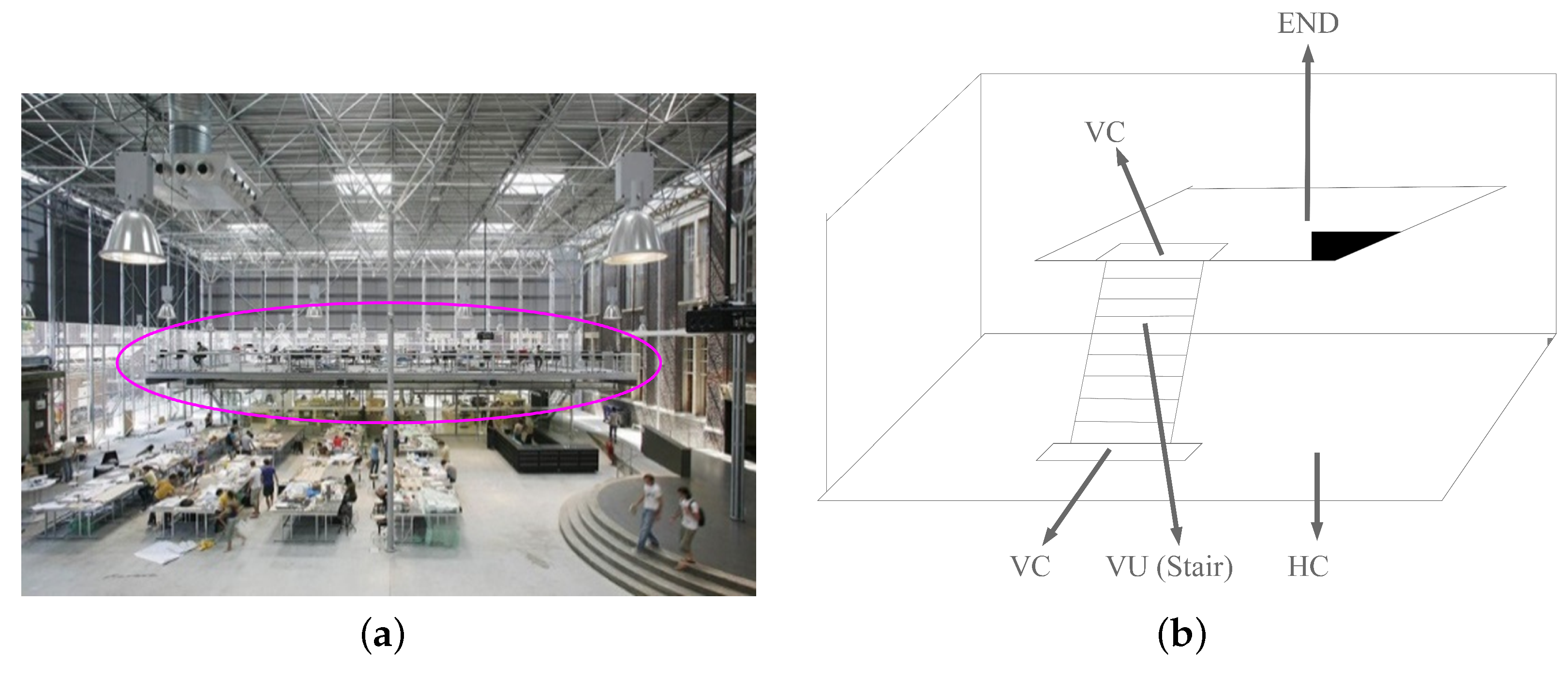
These space semantics can be easily applied for different user-dependent subdivisions. The granularity of subdivision determines the number of logical nodes. The proposed semantics is independent of the shape of spaces and can be applied to any subdivision of a building. Figure 3 shows a complex indoor environment containing intermediate levels (a platform inside a large hall). The functionality of each space is clearly assigned. The platform is an End since it only connects a VC, and this platform is contained in the large hall (which is an HC); and the stair is a VU which connects two VCs. One of the VCs links to the ground of the hall, and the other leads to the platform (the End). In this paper, we select the structural subdivision of building since it keeps the physical space boundaries (e.g., walls).
These proposed space semantics are defined with their intrinsic relationships, and logical paths can be searched according to the semantic classification. In the next section, we introduce the designed routing criteria based on these space semantics.
4. Routing Criteria Based on Space Semantics
We design criteria which can be used to indicate different preferences for space selection. We consider two optimization factors to compute logical paths: the number of spaces and the given semantics of spaces. Firstly, according to human’s cognition of a logical path, fewer spaces in a path can save a user’s cognitive affordance. Thus, the first routing criterion is designed to minimize the number of spaces for a path (i.e., NU), and it is named Fewest Navigable Unit. Secondly, a logical path consists of horizontal and vertical parts. Two classes, HC and VU, generally indicate the horizontal and vertical movements. Therefore, the five other routing criteria are proposed to emphasize HCs/VUs for path options.
The five criteria are designed by considering HC/VU and the number of them. The criteria Fewest Horizontal Connector and Horizontal Connector Prior are proposed to minimize the HC number and to prioritize the HCs in a path, respectively. Similarly, Fewest Vertical Unit is proposed to minimize the VU number, and Vertical Unit Prior is designed to prioritize the VUs in a path. In addition, centrality of HC is considered. An HC indicates multiple options for the next move, and we prefer the most central one for transition in a building. Thus, the criterion Central Horizontal Connector prioritizes the HCs with high accumulated centrality.
In a network, the centrality of a node stands for its accessibility and importance to others [44]. There are different definitions of centrality such as degree, betweenness and closeness. The degree of nodes indicates the number of nodes linking to a node. The closeness is the average length of the shortest paths between the node and all other nodes in the same network [45,46]. In this sense, a node is “central” when it is close to all the other nodes. The betweenness of a node is the ratio of the number of shortest paths (in depth) via the node and that of all the shortest paths (among all the possible pairs of start and target nodes) [47]. We adopt the betweenness as the value of centrality for a logical network since it refers to the “pivot” nodes. The higher is the node betweenness, the more times it bridges other nodes.
We propose the above criteria to minimize node/edge weights to form a logical path. The weight of a node indicates its significance in the logical network for a specific purpose. We define the six routing criteria in the optimization form as follows:
For all the M nodes in the set of a logical network , the weight set is W, and the class of a node n is denoted with .
- Fewest Navigable Unit (Fewest NU): .
- Fewest Horizontal Connector (Fewest HC): .
- Fewest Vertical Unit (Fewest VU): .
- Central Horizontal Connector (Central HC): .
- Horizontal Connector Prior (HC Prior): .
- Vertical Unit Prior (VU Prior): .
Different node weights are employed in the above definitions. For the purpose of minimization, the following values are used: 0 means the node is neutral (does not affect the result) to the path computation (see Table 1); a relatively large value 10,000 means the lower priority of node, i.e., a user tries not to adopt the node in a path; and the lower value 1 means the node is preferred. The nodes with value 1 are equally important in a path.
In general, these routing criteria rely only on NU, HC and VU nodes, and the start and the target nodes. Three subclasses of the VU class are also adopted: Escalator (ES), Stair (ST) and Elevator (EL). Thus, the Fewest VU and VU Prior criteria have more derivatives, i.e., Fewest ES, Fewest ST, Fewest EL, ES Prior, ST Prior, and EL Prior (see Table 1). No weights are set for END nodes since they are not considered for transition. Table 1 presents all the node weights for the six proposed criteria and their variants (e.g., the Fewest EL is a variant of the Fewest VU). All the criteria are separated into two groups: (1) minimizing specific type; and (2) setting priority to specific types. The first group aims to minimize the nodes with the given space class (e.g., HC) in a logical path, regardless of the others (e.g., VC and VU). The second group sets the priority for the given space class and also averts the other space classes as much as possible.
Specially, in the Central HC criterion, the HC nodes are set to the value subtracting their centrality from 10,000. Because this criterion aims to collect the highest accumulated centrality of nodes in a direct path by minimizing weights, the weight (centrality value) is adapted to the monotonicity of the minimization by subtracting the centrality from the upper bound 10,000. Besides, in the definition of VU Prior, is the step from the start to the VU node. As the VU Prior paths give priority to the closest VU node to the start, thus the closer VU has a lower weight (i.e., a smaller ).
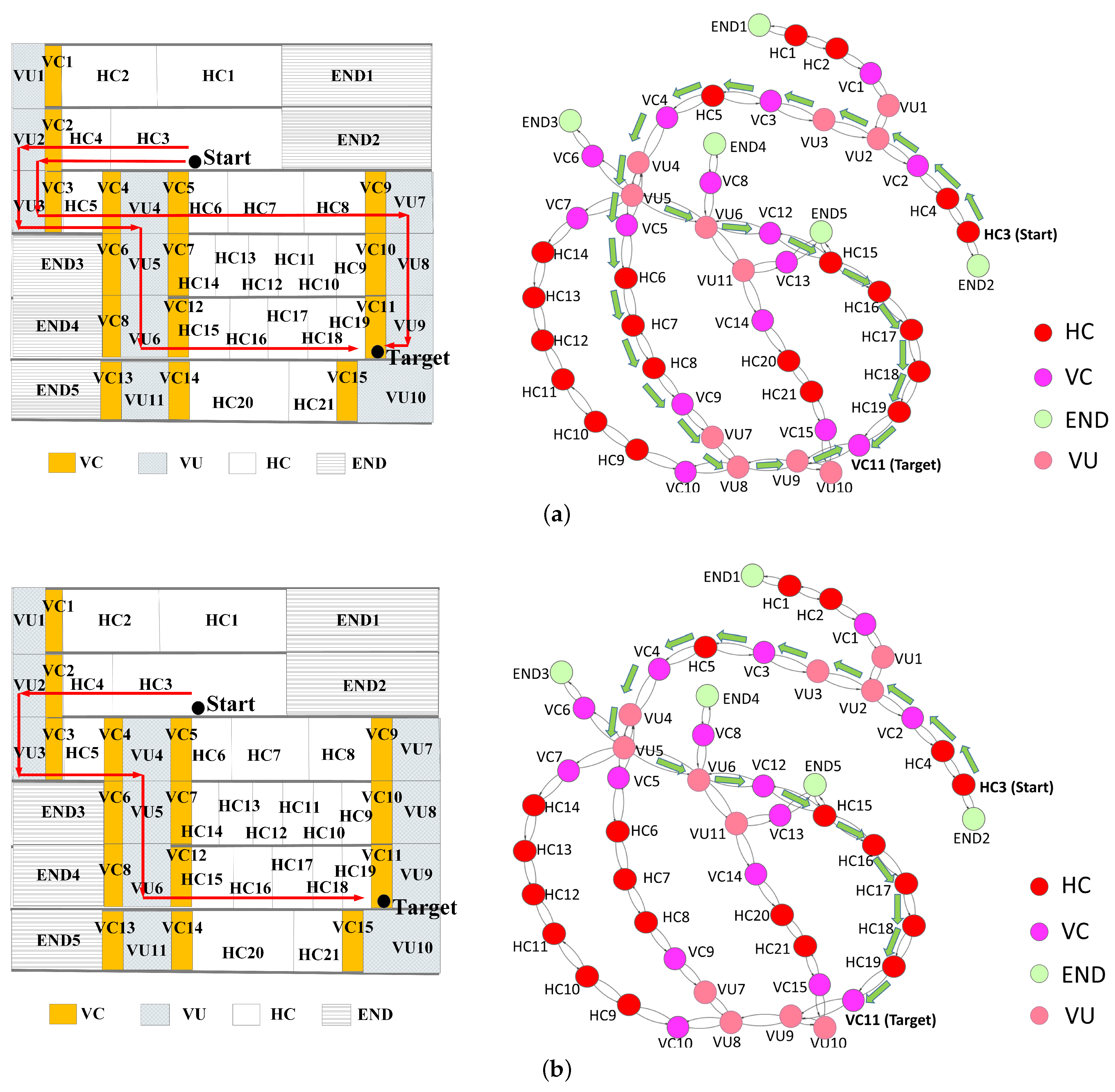
The above concepts are illustrated with the following examples. Figure 4 presents an artificial building in the front view. Figure 4a presents a Fewest NU path including the fewest number of spaces passed by a user. Figure 4b shows the logical network with a Fewest VU path between the start and the destination.
Figure 4c presents a Fewest HC path where the user transits stairs and passes only four HCs (HC4, HC5, HC20 and H21) to arrive at the target. Figure 4d presents an example of a HC prior path that crosses eight HCs (HC4, HC5, HC14, HC13, HC12, HC11, HC10 and HC9) to reach the target. Compared to the Fewest HC path, the HC prior path includes more HCs and fewer VUs. In contrast, the Fewest HC path has the fewest HCs, irrespective of the number of VUs.
5. Routing Procedure
Section 4 introduces the six proposed criteria, and explains how to define node weights of a logical network for different criteria. In this section, we provide the routing process with these criteria. As a routing result, a user can receive one or more logical paths or “No Path” message with the selected criterion.
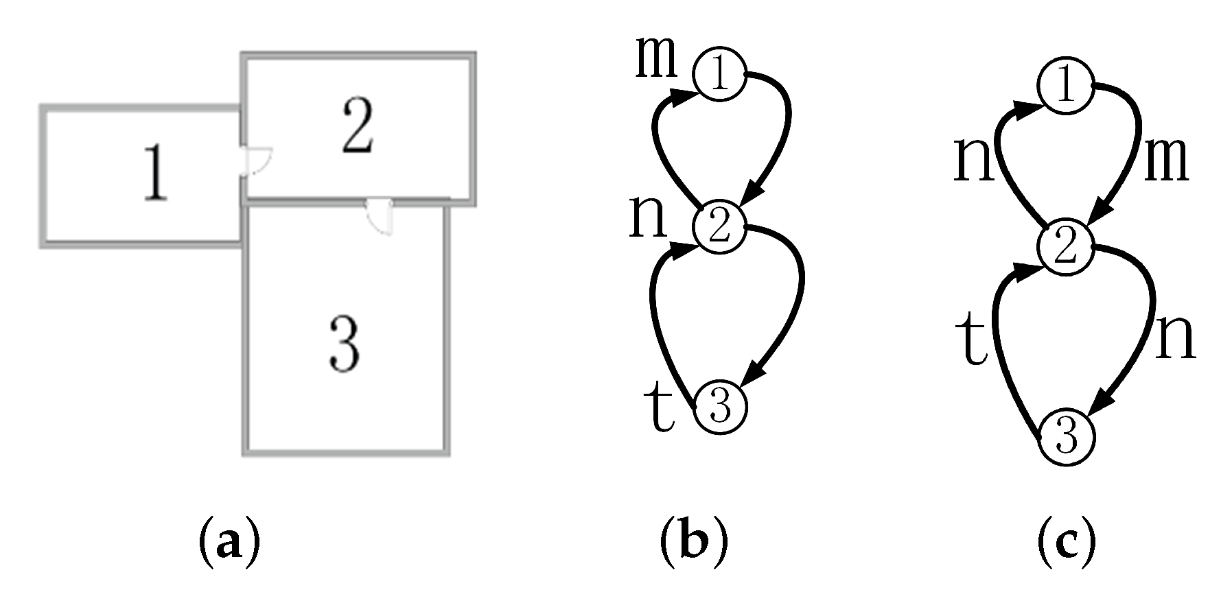
Using a shortest-path algorithm (e.g., Dijkstra [21]), we need edge weights of the logical network. Thus, node weights are transformed to edge weights. We decide to use outgoing edges to define edge weights. As a NU is abstracted as a node of logical network, the inside of the NU is skipped. In this sense, these outgoing edges imply the detailed movement inside this NU. Accordingly, the outgoing edges in a path represent the motion through the related nodes. Given a node weight, Algorithm 1 presents the method that converts the values of nodes to those of related edges. For each node, the algorithm locates first the outgoing edges of the node, and then set the node’s value to all these outgoing edges. Figure 5a shows three rooms, and Figure 5b presents their logical network and the attribute values (i.e., m, n and t) of the nodes. Figure 5c presents the derived edge weights.
Routing with multiple criteria can result in more understandable logical paths. For example, we select a Central HC path from a group of Fewest HC paths. In this case, the selected path contains the fewest HCs and these HCs have high centrality. Therefore, we can more precisely justify logical paths by applying these criteria together.
| Algorithm 1 Derive edge weights from node weights in a logical network. |
| Input: A logical network G, the values Ws of node weights. Output: The logical network G where the edges have been weighted in light of Ws.
|
Routing with multiple criteria can also reduce the number of paths. Multiple logical paths may be derived with a singular criterion. To find a subset of the “better” paths for users, multiple criteria are employed in sequence (the 1st, 2nd, 3rd, etc.) for routing. In this paper, we suppose that a user is offered a priority description of criterion preference. All the collected preferences are sorted in a priority ordering.
Algorithm 2 presents the computation process with a priority ordering of multiple criteria. By following the Lexicographical Goal Programming [22], this procedure is to compute a set Sp including all the logical paths with the first criterion (Lines 3–5). Second, it continually selects paths from Sp with the next criterion, and then replaces Sp with the newly selected paths (Lines 6–9). If there is only one path in Sp, then it is the final path (Line 12). Otherwise, this procedure keeps selecting paths from Sp according to the next criterion in the order. If all the criteria in the priority ordering have been applied and Sp still includes multiple paths, then all the paths in Sp are regarded as the final paths. Ultimately, the set Sp includes all the logical paths resulting from the priority ordering. This computation obtains either one path or several equally-optimal paths. Figure 6 presents the workflow of routing with priority ordering. In practice, the importance of each criterion is sorted for distinct users.
To sum up, to compute logical paths with multiple criteria for a specific user, the computation requires: (1) a user-related logical network; (2) a priority ordering of criteria to the user; and (3) the routing workflow. The resulting paths are regarded with the same importance. In an application, one can visualize all these paths and ask the user to select one, or randomly choose one.
| Algorithm 2 Compute logical paths with ordered criteria in a priority list on a logical network. |
| Input: A prioritized list of ordered routing criteria F, a logical network N. Output: The set of logical path(s) .
|
6. Experiments
In this section, we aim to demonstrate the usability of this routing method. We applied the six proposed routing criteria to the logical networks of two buildings. This first test was to compare the routing results in a complete building and the second test was to distinguish the results on a floor only. We included MicroStation V8i of Bentley Systems [48] for building data visualization and igraph (an open-sourced Python package) [49] for routing computation and visualization. In addition, we collected the most commonly available data source of buildings, i.e., floor plans in images. The test floor plans were extracted from two buildings. The first one was re-created from the image of Schiphol Airport, the Netherlands (Figure 7a). The data contain stairs, elevators and escalators. The other dataset is the first floor of the Museum of Fine Arts (MFA), Boston, USA (Figure 8a). Stairs and elevators related to this floor were included but not used, because this plan was used to test routing on only one floor.
We followed the same method to generate the logical network from floor plans in Reference [50]. The geometry of the floor plans were manually drawn and stored in a Bentley DGN file. For instance, a “Space” layer contains the geometry of HUs, a “VU” layer for vertical passages, and an “Opening” layer with all openings of the building (e.g., door spaces). Specially, different subtypes of VU were clarified, i.e., Stair, Escalator, and Elevator. The geometry of spaces were manually created as 2D/3D floor surfaces of HUs and openings. We ensured that doors overlap the corresponding spaces. This overlap was designed to support automatic detection of the connection of spaces: the connection between two spaces can be detected from the “space–door–space” relationships. As a result, the logical network was automatically generated based on these connections.
The floor plans of Schiphol Airport are considered a complex building including large irregular shaped spaces. The first floor of the MFA includes plenty of spaces and many of them are passages (HC in Figure 8b), which is a typical case to test multiple paths between two spaces on a floor. The logical networks of Schiphol Airport and the MFA floor are shown in Figure 7b and Figure 8b. Some VU nodes in the network of the MFA floor appear to be End nodes (see Figure 8b) because the other related destination floors are not presented.
The logical network was derived according to a specific user’s motion ability (e.g., walking or with wheel devices). A routing path was denoted by a list of nodes, and we adopted the notation “id + semantics” to name these nodes (e.g., 64HC means node 64 is an HC space). For routing with multiple criteria, the priority ordering of criteria was assumed for specific users.
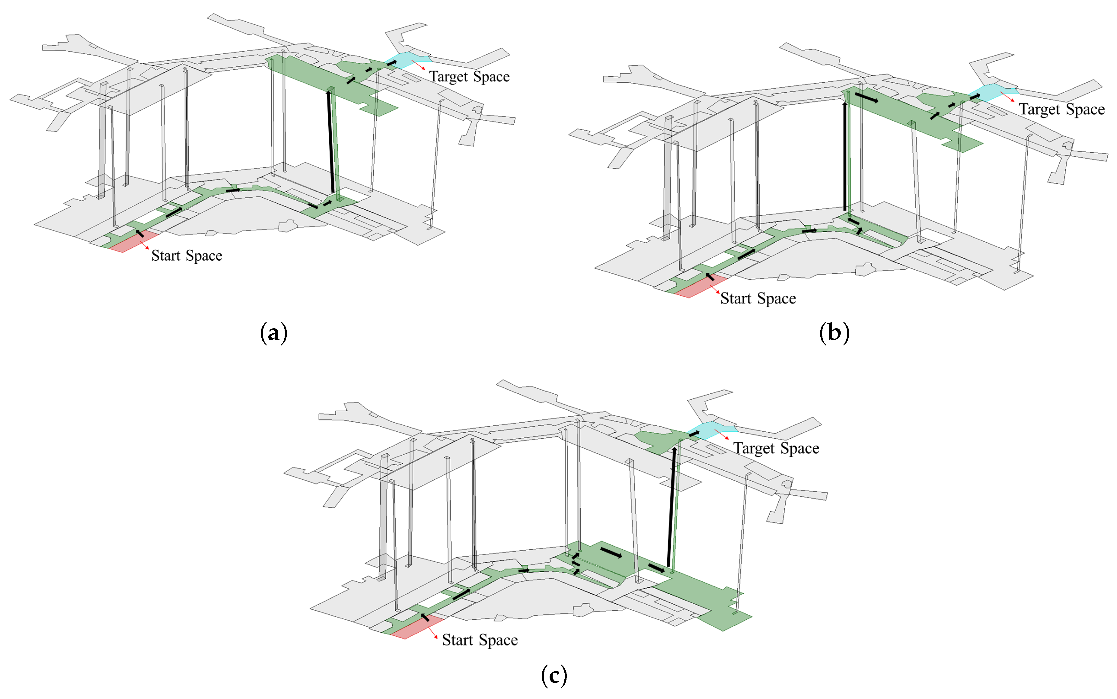
We applied the six criteria to two spaces (Spaces 1 and 42) on the logical network of Schiphol Airport. In Figure 9, logical paths are visualized as a sequence of spaces, which provides a clear overview about these paths. Routing with the six criteria covered a set of three paths. These paths are denoted as follows:
- p1: 1END, 64HC, 62HC, 72HC, 71VC, 54Stair, 88VC, 90HC, 70HC, 42HC;
- p2: 1END, 64HC, 62HC, 87HC, 86VC, 61Ele, 89VC, 90HC, 70HC, 42HC;
- p3: 1END, 64HC, 62HC, 87HC, 76HC, 74VC, 58Ele, 69VC, 70HC, 42HC.
The routing results of each criterion are given in Table 2. The criteria Fewest NU, Fewest HC and Fewest VU resulted in the three paths p1, p2 and p3. VU prior resulted in fewer paths including p1 and p2. This because the first VU (54Stair and 61Ele) in p1 and p2 are close to the start (1END). HC prior related to one path p3 since it contains the longest HC chain (4 HC spaces 64HC, 62HC, 87HC, 76HC). In this case, the user moves horizontally as much as possible before the floor changes. The central HC path was p1, which indicates the path involves the highest accumulated centrality of related spaces. Intuitively, the high centrality of p1 means the path lies in the central regions of the airport.
Similarly, a routing test was also conducted in MFA (Figure 10). Except Fewest VU and VU prior, the other four criteria were applied to two spaces (Spaces 130 and 93). These paths did not involve switching floors (i.e., without VU). The resulting path set contained two paths r1 and r2 (see Table 3):
- The sequence of r1 is 130HC, 10HC, 30HC, 31HC, 32HC, 52HC, 27HC, 122HC, 97HC, 98HC, 79HC, 93HC.
- The sequence of r2 is 130HC, 10HC, 33HC, 34HC, 118HC, 42HC, 80HC, 84HC, 85HC, 86HC, 109HC, 93HC.
Fewest NU, Fewest HC and HC prior resulted in the same path set including r1 and r2. However, Path r1 was selected by the criterion central HC (see Figure 10a). Notably, the two paths consist of only HC nodes since the visitor does not change floors.
In both Schiphol Airport and MFA, multiple logical paths exist between the given start and target spaces. In such a case, it is necessary to select the proper logical path when the user requests a definite path. Considering the same start and target spaces (1 and 42) in Schiphol Airport, we suppose the user profile is an adult visitor with effort-saving-motion, and the user is a traveler with luggage who needs elevators and heads to a fixed check-in point. This is a typical profile for travelers since most of them bring some luggage on trolleys. Elevator is specified since it saves the traveler effort to bring the luggage. We assigned a related priority ordering for routing on the logical network, i.e., [Fewest NU, Elevator (VU) prior]. Accordingly, we obtained Path p2 for this user (see Figure 9b).
We also conducted routing with multiple criteria in MFA (Figure 8). The visitor is assumed to be an adult in walking. A priority ordering was set for two routing criteria: (1) Fewest HC; and (2) Central HC. This ordering means firstly the visitor needs to walk to the target room by crossing the fewest HC on the same floor, and secondly she/he aims to pass through the central section. After applying the criterion Fewest HC to the logical network, two logical Paths r1 and r2 were obtained. A unique Path r1 (see Figure 10a) was selected after applying central HC. This unique path has higher node centrality and it is relatively easy to alter the path at each node.
7. Discussions
For the Schiphol Airport, Table 4 lists five pairs of start and target spaces with the logical paths of each pair. All paths derived with the six criteria are added in the column “Path Set”, and each path has an id (e.g., A1, see Table 5).
Table 5 presents the path ids of each criterion. The paths derived with Fewest HC are the same as the Fewest NU paths since they pass through the same number of HC (see the node ids in Table 4). Similarly, the Fewest VU paths are the same to the Fewest NU paths due to the identical VUs. Each Fewest VU path in Table 5 contains only one VU to switch the floor. As the Fewest NU indicates the fewest spaces, and each Fewest VU path contains only one VU, and then the number of the HC in these paths are also the fewest (e.g., the Fewest HC paths).
The paths derived with HC prior and VU prior have no overlap (see Table 5), which aligns with the designed purpose separating the priority of using HC and VU. In addition, paths derived with HC prior and Central HC have no clear relationships. The centrality (betweenness) is about the node importance in the network. The result indicates that HC prior paths may not select the HCs with high centrality.
To investigate the connectedness of the tested buildings, the distribution of node degrees of their logical networks were compared. The ratio of Connector nodes (degree ≥ 4) to all nodes (Connector ratio for short) was calculated for each logical network. A high ratio indicates that many Connectors exist and may increase path choices between two locations in the building. In this sense, buildings with a high Connector-ratio are regarded as complex.
Table 6 presents the Connector ratio of the two logical networks. Schiphol Airport and MFA contain the high ratios of 35.79% and 34.35%, respectively. It means the two buildings have a highly connected logical network.
For a given building subdivision, the existence of multiple logical paths depends on the location of the start and target spaces. For example, the multiple Fewest VU paths of the five space pairs in Schiphol Airport reveal the available VUs (Table 4 and Table 5). In contrast, even in the complex building with many Connectors, it is still possible to obtain only one logical path to a target space (such as paths of “HC Prior” and “Central HC” in Table 2).
Even after applying a priority ordering of criteria, there can be still multiple logical paths between two spaces. To handle the multiple paths, three methods could be applied: (1) to provide all the logical paths to a user; (2) to ask a user to select one of them; and (3) to compute all their corresponding geometric paths, and then select the logical path regarding the “best” geometric path (e.g., the “shortest;’ one). In this paper, we adopt the first choice, i.e., providing all the logical paths to users.
Routing on logical networks is related to the subdivision of building. As shown in Table 6, although Schiphol Airport has much larger area than the MFA building, the number of nodes (i.e., spaces) of MFA (131) is more than those of Schiphol Airport (95). If a building subdivision results in a few large spaces, then the logical network would provide more abstract path information. For example, according to the structural subdivision, Schiphol Airport consists of several large spaces where users need more path details (e.g., turns) inside them (see Figure 9). This indicates that the length of two different logical paths cannot be precisely compared by their related space numbers.
For more precisely comparing the length of paths, a solution is to subdivide large spaces into similar sizes. For example, by setting a maximum size, one can subdivide these large spaces until their sizes are lower than/equal to the maximum size (e.g., meshing). As shown in Figure 11, a long space in Schiphol Airport can be subdivided into 16 small spaces that have similar sizes. Movement in these small spaces would result in similar distances. However, in this case, many conceptual boundaries (the dashed lines) need to be introduced, which makes these spaces difficult to be perceived.
8. Conclusions
In this paper, we present an innovative approach for routing on the logical network, i.e., to compute logical paths for users based only on space semantics. In such a routing process, geometric details are not required. The paths are computed on a logical network created from the connectivity between semantically defined spaces. The path computation then aims at: (1) minimizing the number of spaces of a given semantics; or (2) prioritizing a specific space semantics and/or using graph properties of the logical network.
We proposed and tested six routing criteria: (1) Fewest Navigable Unit minimizes the number of traversed navigable spaces; (2) Fewest Horizontal Connector minimizes the number of HC in a path; (3) Fewest Vertical Unit minimizes the number of VU in a path; (4) Central Horizontal Connector preserves the high accumulated centrality of HC in a path; (5) Horizontal Connector Prior prioritizes continuous HC nodes; and (6) Vertical Unit Prior prioritizes VU nodes.
We provided a proof-of-concept implementation of this routing method and demonstrated its feasibility in two buildings. The implementation clearly reveals several advantages of the proposed method. The approach does not depend on the shape of the spaces in a building and therefore it can be used for any type of building. The semantic hierarchy of spaces and the corresponding logical network can be created with verbal descriptions only and therefore the approach is appropriate even for buildings that are lacking in digital models. Original building spaces (e.g., an entrance hall) can be subdivided into smaller parts (e.g., waiting areas) with the purpose of being used for different types of user. However, the logical routing method can be applied to the spaces with any subdivision. Our experiments showed that logical paths can be very flexible and computed with a singular criterion or multiple criteria. The prioritization of multiple criteria is used to provide one unique path, but in many cases the path selection from multiple equivalent options might be left to the user. A wayfinder can choose the final option with the visualization of all available logical paths. We believe this approach opens the door for a new type of routing that can be better adapted to the cognition needs of human users.
We envisage three topics which need further investigation and developments: (1) to extend and elaborate the routing criteria; (2) to test more semantic hierarchies and subdivision methods to derive a logical network; and (3) to explore more options and the mechanism to combine logical routing with routing on a geometric network. The proposed criteria in this paper are definitely not an exhaustive list. More routing criteria can be designed for other user needs regarding space selection. In this approach, we have used our designed semantics, but other semantics and ontologies have to be considered. A very interesting topic is the space subdivision. The semantics of each space can be further extended, and more relationships such as containment can be considered, which brings other interesting cases for logical routing. Then, the routing based on different subdivisions should be investigated and validated for different situations. Another interesting direction for research is the integration with routing on geometric networks. Geometric properties (size, distance and slope) of indoor space can also be included as parameters in the logical network. For example, a user may select a wider and straighter HC for transition among multiple paths.
Author Contributions
Conceptualization, L.L. and S.Z.; original draft, L.L., S.Z., B.L. and P.v.O.; methodology, L.L., S.Z., P.v.O., B.L. and H.L.; investigation, L.L.; supervision, S.Z. and B.L.; and writing—review and editing, L.L., S.Z., J.B., B.L. and H.L.
Funding
This research was funded by National Natural Science Foundation of China (41574023, 41622401 and 41471324), Scientific and Technological Innovation Plan from Shanghai Science and Technology Committee (17511109501, 17DZ1100802, and 17DZ1100902), and National Key Research and Development Program of China (2016YFB0501802).
Conflicts of Interest
The authors declare no conflict of interest.
References
- Lee, J. A Spatial Access-Oriented Implementation of a 3-D GIS Topological Data Model for Urban Entities. GeoInformatica 2004, 8, 237–264. [Google Scholar] [CrossRef]
- Kwan, M.P.; Lee, J. Emergency response after 9/11: The potential of real-time 3D {GIS} for quick emergency response in micro-spatial environments. Comput. Environ. Urban Syst. 2005, 29, 93–113. [Google Scholar] [CrossRef]
- Pu, S.; Zlatanova, S. Evacuation Route Calculation of Inner Buildings. In Geo-Information for Disaster Management; Van Oosterom, P., Zlatanova, S., Fendel, E., Eds.; Springer: Berlin/Heidelberg, Germany, 2005; pp. 1143–1161. [Google Scholar]
- Boguslawski, P.; Gold, C. Euler operators and navigation of multi-shell building models. In Developments in 3D Geo-Information Sciences; Springer: Berlin/Heidelberg, Germany, 2010; pp. 1–16. [Google Scholar]
- Worboys, M. Modeling Indoor Space. In Proceedings of the 3rd ACM SIGSPATIAL International Workshop on Indoor Spatial Awareness, Chicago, IL, USA, 1 November 2011; ACM: New York, NY, USA, 2011; pp. 1–6. [Google Scholar]
- Stoffel, E.P.; Schoder, K.; Ohlbach, H.J. Applying Hierarchical Graphs to Pedestrian Indoor Navigation. In Proceedings of the 16th ACM SIGSPATIAL International Conference on Advances in Geographic Information Systems, Irvine, CA, USA, 5–7 November 2008; ACM: New York, NY, USA, 2008. [Google Scholar]
- Zheng, J.; Winstanley, A.C.; Pan, Z.; Coveney, S. Spatial Characteristics of Walking Areas for Pedestrian Navigation. In Proceedings of the Third International Conference on Multimedia & Ubiquitous Engineering, Qingdao, China, 4–6 June 2009. [Google Scholar]
- Liu, L.; Zlatanova, S. A two-level path-finding strategy for indoor navigation. In Intelligent Systems for Crisis Management; Springer: Berlin/Heidelberg, Germany, 2013; pp. 31–42. [Google Scholar]
- Lin, Z.; Xu, Z.; Hu, D.; Hu, Q.; Li, W. Hybrid Spatial Data Model for Indoor Space: Combined Topology and Grid. ISPRS Int. J. Geo-Inf. 2017, 6, 343. [Google Scholar] [CrossRef]
- Nagel, C.; Stadler, A.; Kolbe, T. Conceptual requirements for the automatic reconstruction of building information models from uninterpreted 3D models. In Proceedings of the International Archives of Photogrammetry, Remote Sensing and Spatial Information Sciences, Vancouver, BC, Canada, 27–31 July 2009; Copernicus Publications: Göttingen, Germany, 2009; pp. 46–53. [Google Scholar]
- Afyouni, I.; Ray, C.; Claramunt, C. Spatial models for context-aware indoor navigation systems: A survey. J. Spat. Inf. Sci. 2012, 4, 85–123. [Google Scholar] [CrossRef]
- Vasardani, M.; Winter, S.; Richter, K.F. Locating place names from place descriptions. Int. J. Geogr. Inf. Sci. 2013, 27, 2509–2532. [Google Scholar] [CrossRef]
- Winter, S.; Hamzei, E.; Van de Weghe, N.; Ooms, K. A Graph Representation for Verbal Indoor Route Descriptions. In Proceedings of the German Conference on Spatial Cognition, Tuebingen, Germany, 5–8 September 2018; Springer: Cham, Switzerland, 2018; pp. 77–91. [Google Scholar]
- Goetz, M.; Zipf, A. Extending OpenStreetMap to indoor environments. In Urban and Regional Data Management; CRC Press: Leiden, The Netherlands, 2011; pp. 51–61. [Google Scholar]
- Yang, L.; Worboys, M. A Navigation Ontology for Outdoor-indoor Space: (Work-in-progress). In Proceedings of the 3rd ACM SIGSPATIAL International Workshop on Indoor Spatial Awareness, Chicago, IL, USA, 1 November 2011; ACM: New York, NY, USA, 2011; pp. 31–34. [Google Scholar]
- Lee, J.; Li, K.; Zlatanova, S.; Kolbe, T.; Nagel, C.; Becker, T. IndoorGML. Standard, The Open Geospatial Consortium (OGC); IndoorGML: London, UK, 2014. [Google Scholar]
- Vanclooster, A.; De Maeyer, P.; Fack, V.; Van de Weghe, N. Calculating least risk paths in 3D indoor space. In Innovations in 3D Geo-Information Sciences; Springer: Cham, Switzerland, 2014; pp. 13–31. [Google Scholar]
- Vanclooster, A.; Ooms, K.; Viaene, P.; Fack, V.; Weghe, N.V.D.; Maeyer, P.D. Evaluating suitability of the least risk path algorithm to support cognitive wayfinding in indoor spaces: An empirical study. Appl. Geogr. 2014, 53, 128–140. [Google Scholar] [CrossRef]
- Stoffel, E.P. Hierarchical Graphs as Organisational Principle and Spatial Model Applied to Pedestrian Indoor Navigation. Ph.D. Thesis, Ludwig-Maximilians-Universität München, Munich, Germany, 2009. [Google Scholar]
- Belouaer, L.; Brosset, D.; Claramunt, C. From verbal route descriptions to sketch maps in natural environments. In Proceedings of the 24th ACM SIGSPATIAL International Conference on Advances in Geographic Information Systems, Burlingame, CA, USA, 31 October–3 November 2016. [Google Scholar]
- Dijkstra, E. A note on two problems in connexion with graphs. Numer. Math. 1959, 1, 269–271. [Google Scholar] [CrossRef]
- Jones, D.; Tamiz, M. Practical Goal Programming; Springer: Boston, MA, USA, 2010; Volume 141. [Google Scholar]
- Lee, J.; Kwan, M.P. A combinatorial data model for representing topological relations among 3D geographical features in microspatial environments. Int. J. Geogr. Inf. Sci. 2005, 19, 1039–1056. [Google Scholar] [CrossRef]
- Ye, J.; Coyle, L.; Dobson, S.; Nixon, P. A Unified Semantics Space Model. In Location- and Context-Awareness; Hightower, J., Schiele, B., Strang, T., Eds.; Springer: Berlin/Heidelberg, Germany, 2007; Volume 4718, pp. 103–120. [Google Scholar]
- Lee, K.; Kang, H.Y.; Lee, J. Topological Analysis in Indoor Shopping Mall using Ontology. J. Korean Soc. Surv. Geod. Photogram. Cartogr. 2013, 31, 405–415. [Google Scholar] [CrossRef]
- Li, D.; Lee, D.L. A topology-based semantic location model for indoor applications. In Proceedings of the ACM Sigspatial International Conference on Advances in Geographic Information Systems, Irvine, CA, USA, 5–7 November 2008; pp. 1–10. [Google Scholar]
- Jiang, S.; Feng, Z.; Zhang, X.; Wang, X.; Rao, G. A Multi-dimension Weighted Graph-Based Path Planning with Avoiding Hotspots. In Knowledge Graph and Semantic Computing: Semantic, Knowledge, and Linked Big Data; Chen, H., Ji, H., Sun, L., Wang, H., Qian, T., Ruan, T., Eds.; Springer: Singapore, 2016; pp. 15–26. [Google Scholar]
- Ohlbach, H.J.; Rosner, M.; Lorenz, B.; Stoffel, E.P. NL Navigation Commands from Indoor WLAN Fingerprinting Position Data; Technical Report; University of Munich: Munich, Germany, 2006. [Google Scholar]
- Stoffel, E.P.; Lorenz, B.; Ohlbach, H.J. Towards a Semantic Spatial Model for Pedestrian Indoor Navigation. In Proceedings of the 2007 Conference on Advances in Conceptual Modeling: Foundations and Applications, Auckland, New Zealand, 5–9 November 2007; Springer: Berlin/Heidelberg, Germany, 2007; pp. 328–337. [Google Scholar]
- Becker, T.; Nagel, C.; Kolbe, T. A Multilayered Space-Event Model for Navigation in Indoor Spaces. In 3D Geo-Information Sciences; Lee, J., Zlatanova, S., Eds.; Lecture Notes in Geoinformation and Cartography; Springer: Berlin/Heidelberg, Germany, 2009; pp. 61–77. [Google Scholar]
- Zlatanova, S.; Liu, L.; Sithole, G. A conceptual framework of space subdivision for indoor navigation. In Proceedings of the Fifth ACM SIGSPATIAL International Workshop on Indoor Spatial Awareness, Orlando, FL, USA, 5–8 November 2013; pp. 37–41. [Google Scholar]
- Richter, K.F.; Winter, S.; Santosa, S. Hierarchical representations of indoor spaces. Environ. Plan. B Plan. Des. 2011, 38, 1052–1070. [Google Scholar] [CrossRef]
- Krūminaitė, M.; Zlatanova, S. Indoor space subdivision for indoor navigation. In Proceedings of the Sixth ACM SIGSPATIAL International Workshop on Indoor Spatial Awareness, Dallas, TX, USA, 4–7 November 2014; pp. 25–31. [Google Scholar]
- Tsetsos, V.; Anagnostopoulos, C.; Kikiras, P.; Hasiotis, P.; Hadjiefthymiades, S. A human-centered semantic navigation system for indoor environments. In Proceedings of the International Conference on Pervasive Services 2005, Santorini, Greece, 11–14 July 2005; pp. 146–155. [Google Scholar]
- Dudas, P.; Ghafourian, M.; Karimi, H. ONALIN: Ontology and algorithm for indoor routing. In Proceedings of the 2009 Tenth International Conference on Mobile Data Management: Systems, Services and Middleware, Washington, DC, USA, 18–20 May 2009; pp. 720–725. [Google Scholar]
- Karimi, H.; Ghafourian, M. Indoor Routing for Individuals with Special Needs and Preferences. Trans. GIS 2010, 14, 299–329. [Google Scholar] [CrossRef]
- Khan, A.; Kolbe, T. Constraints and their role in subspacing for the locomotion types in indoor navigation. In Proceedings of the 2012 International Conference on Indoor Positioning and Indoor Navigation (IPIN), Sydney, NSW, Australia, 13–15 November 2012; p. 12. [Google Scholar]
- Alattas, A.; Zlatanova, S.; Van Oosterom, P.; Chatzinikolaou, E.; Lemmen, C.; Li, K.J. Supporting Indoor Navigation Using Access Rights to Spaces Based on Combined Use of IndoorGML and LADM Models. ISPRS Int. J. Geo-Inf. 2017, 6, 384. [Google Scholar] [CrossRef]
- Liu, L.; Zlatanova, S. A Semantic Data Model for Indoor Navigation. In Proceedings of the Fourth ACM SIGSPATIAL International Workshop on Indoor Spatial Awareness, New York, NY, USA, 6 November 2012; ACM: New York, NY, USA, 2012; pp. 1–8. [Google Scholar]
- Brown, G.; Nagel, C.; Zlatanova, S.; Kolbe, T. Modelling 3D topographic space against indoor navigation requirements. In Progress and New Trends in 3D Geoinformation Sciences; Springer: Berlin/Heidelberg, Germany, 2013; pp. 1–22. [Google Scholar]
- Caramia, M.; Dell Olmo, P. Multi-objective optimization. In Multi-Objective Management in Freight Logistics: Increasing Capacity, Service Level and Safety with Optimization Algorithms; Springer: London, UK, 2008; pp. 11–36. [Google Scholar]
- Deb, K. Multi-objective Optimization. In Search Methodologies; Burke, E., Kendall, G., Eds.; Springer: Boston, MA, USA, 2014; pp. 403–449. [Google Scholar]
- Lyardet, F.; Szeto, D.; Aitenbichler, E. Context-aware indoor navigation. In Proceedings of the European Conference on Ambient Intelligence, Nuremberg, Germany, 19–22 November 2008; Springer: Berlin/Heidelberg, Germany, 2008; pp. 290–307. [Google Scholar]
- Borgatti, S.P. Centrality and network flow. Soc. Netw. 2005, 27, 55–71. [Google Scholar] [CrossRef]
- Sabidussi, G. The centrality index of a graph. Psychometrika 1966, 31, 581–603. [Google Scholar] [CrossRef] [PubMed]
- Boldi, P.; Vigna, S. Axioms for Centrality. Internet Math. 2013, 10, 222–262. [Google Scholar] [CrossRef]
- Brandes, U. A Faster Algorithm for Betweenness Centrality. J. Math. Sociol. 2001, 25, 163–177. [Google Scholar] [CrossRef]
- Systems, B. I-Models: Access and Share Information-Rich Models. 2016. Available online: https://www.bentley.com/en/i-models (accessed on 1 March 2019).
- Igraph Core Team. Igraph. 2016. Available online: https://pypi.org/project/python-igraph/ (accessed on 1 March 2019).
- Liu, L.; Zlatanova, S. Generating Navigation Models from Existing Building Data. In The International Archives of the Photogrammetry, Remote Sensing and Spatial Information Sciences; Copernicus Publications: Göttingen, Germany, 2013; pp. 19–25. [Google Scholar]
Figure 1.
The class diagram in the Unified Modeling Language (UML). The green part includes the classes representing a logical network’s nodes and edges, while the pale pink part shows the generic space classes.
Figure 1.
The class diagram in the Unified Modeling Language (UML). The green part includes the classes representing a logical network’s nodes and edges, while the pale pink part shows the generic space classes.

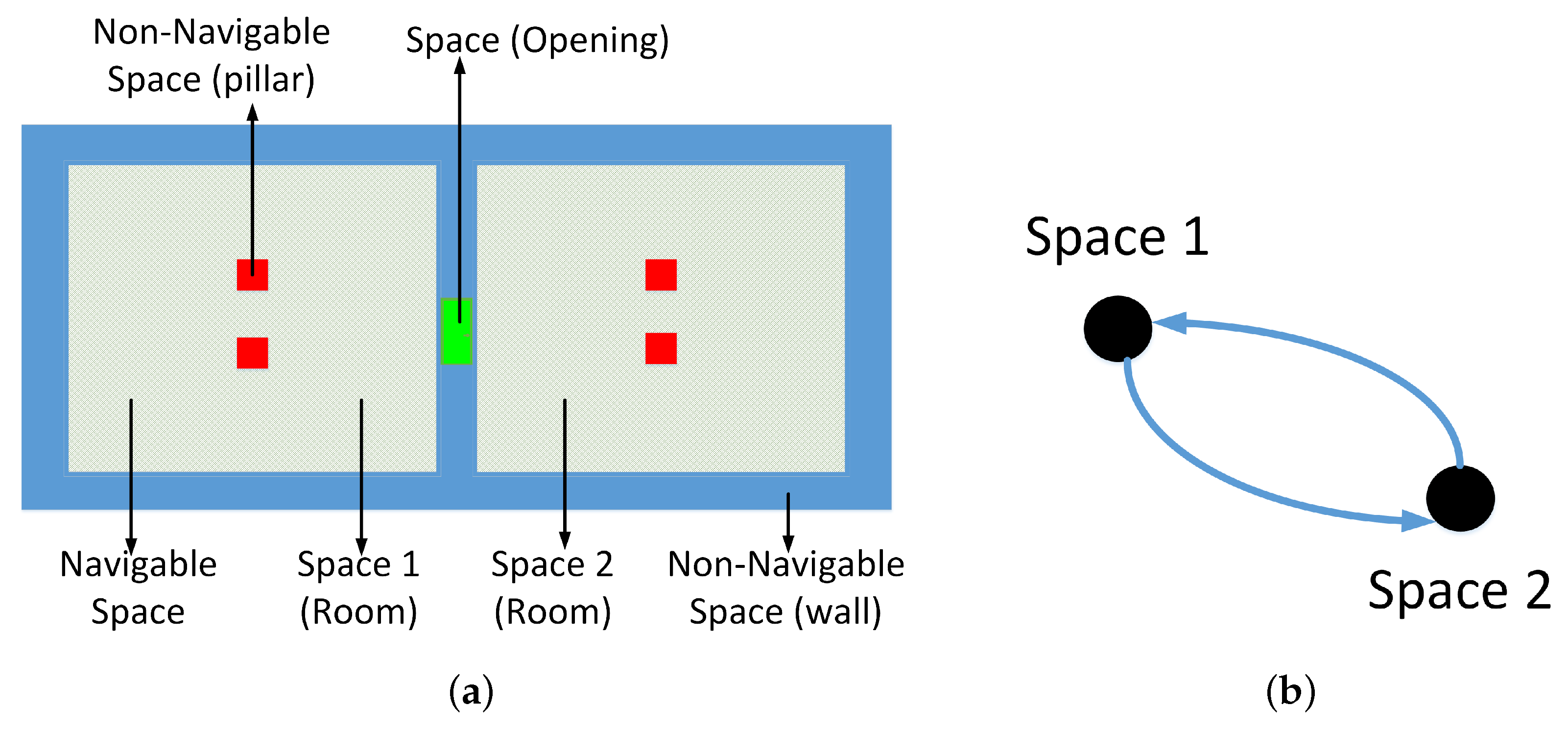
Figure 2.
Concepts of indoor space: (a) description of Space, Navigable Space and Non-Navigable Space; and (b) the logical network of Space 1 and Space 2. The network is bi-directional.
Figure 2.
Concepts of indoor space: (a) description of Space, Navigable Space and Non-Navigable Space; and (b) the logical network of Space 1 and Space 2. The network is bi-directional.

Figure 3.
An example of a complex building depicted by the designed generic space semantics: (a) the platform in the middle of the large hall; and (b) the semantic spaces in this scenario.
Figure 3.
An example of a complex building depicted by the designed generic space semantics: (a) the platform in the middle of the large hall; and (b) the semantic spaces in this scenario.

Figure 4.
Illustration of four criteria in an artificial building: (a) a Fewest NU path; (b) a Fewest VU path; (c) a Fewest HC path; and (d) an HC prior path.
Figure 4.
Illustration of four criteria in an artificial building: (a) a Fewest NU path; (b) a Fewest VU path; (c) a Fewest HC path; and (d) an HC prior path.


Figure 5.
Derivation of edge weights from those of nodes in a logical network. (a) Three rooms; (b) Weights of nodes; and (c) Transition to edge weights.
Figure 5.
Derivation of edge weights from those of nodes in a logical network. (a) Three rooms; (b) Weights of nodes; and (c) Transition to edge weights.

Figure 6.
The workflow of routing with priority ordering of criteria.

Figure 7.
The test data of Schiphol Airport: (a) the digitized floor plans; and (b) the logical network.
Figure 7.
The test data of Schiphol Airport: (a) the digitized floor plans; and (b) the logical network.

Figure 8.
The test data of MFA museum: (a) the digitized floor plans; and (b) the logical network.

Figure 9.
The logical paths between two spaces of Schiphol Airport: (a) Path p1; (b) Path p2; and (c) Path p3. The highlighted spaces represent the related logical paths, and the arrows indicate the direction.
Figure 9.
The logical paths between two spaces of Schiphol Airport: (a) Path p1; (b) Path p2; and (c) Path p3. The highlighted spaces represent the related logical paths, and the arrows indicate the direction.

Figure 10.
Routing with the proposed criteria on the logical network of MFA: (a) Path r1; and (b) Path r2.
Figure 10.
Routing with the proposed criteria on the logical network of MFA: (a) Path r1; and (b) Path r2.

Figure 11.
Illustration of the subdivision of a large space into the smaller ones with similar sizes.
Figure 11.
Illustration of the subdivision of a large space into the smaller ones with similar sizes.


Table 1.
The weights of nodes of the logical network for the proposed criteria.
| Type | Constraint | HC | VC | VU | ||
|---|---|---|---|---|---|---|
| EL | ES | ST | ||||
| Minimizing specific types | Fewest NU | 1 | 1 | 1 | 1 | 1 |
| Fewest HC | 1 | 0 | 0 | 0 | 0 | |
| Fewest VU | 0 | 0 | 1 | 1 | 1 | |
| Fewest EL | 0 | 0 | 1 | 10,000 | 10,000 | |
| Fewest ES | 0 | 0 | 10,000 | 1 | 10,000 | |
| Fewest ST | 0 | 0 | 10,000 | 10,000 | 1 | |
| Fewest EL&ES | 0 | 0 | 1 | 1 | 10,000 | |
| Fewest EL&ST | 0 | 0 | 1 | 10,000 | 1 | |
| Fewest ES&ST | 0 | 0 | 10,000 | 1 | 1 | |
| Setting priority to specific types | Central HC | 10,000-Centrality | 10,000 | 10,000 | 10,000 | 10,000 |
| HC Prior | 1 | 10,000 | 10,000 | 10,000 | 10,000 | |
| VU Prior | 10,000 | 10,000 | 1 + | 1 + | 1 + | |
| EL Prior | 10,000 | 10,000 | 1 + | 10,000 | 10,000 | |
| ES Prior | 10,000 | 10,000 | 10,000 | 1 + | 10,000 | |
| ST Prior | 10,000 | 10,000 | 10,000 | 10,000 | 1 + | |
| EL&ES Prior | 10,000 | 10,000 | 1 + | 1 + | 10,000 | |
| EL&ST Prior | 10,000 | 10,000 | 1 + | 10,000 | 1 + | |
| ES&ST Prior | 10,000 | 10,000 | 10,000 | 1 + | 1 + | |
Table 2.
The logical paths between Nodes 1 and 42 of Schiphol Airport according to the six criteria.
Table 2.
The logical paths between Nodes 1 and 42 of Schiphol Airport according to the six criteria.
| Fewest NU | Fewest HC | Fewest VU | VU Prior | HC Prior | Central HC |
|---|---|---|---|---|---|
| p1, p2, p3 | p1, p2, p3 | p1, p2, p3 | p1, p2 | p3 | p1 |
Table 3.
The logical paths between Nodes 130 and 93 of MFA according to the four criteria.
| Fewest NU | Fewest HC | HC Prior | Central HC |
|---|---|---|---|
| r1, r2 | r1, r2 | r1, r2 | r1 |
Table 4.
All logical paths of five pairs of places in Schiphol Airport.
| Start-Target | Path Set |
|---|---|
| 1–82 | A1: 1END, 64HC, 95HC, 91VC, 53Esc, 96VC, 100HC, 68HC, 82HC A2: 1END, 64HC, 95HC, 85HC, 84VC, 56Esc, 67VC, 68HC, 82HC A3: 1END, 64HC, 62HC, 87HC, 76HC, 73VC, 57Stair, 81VC, 82HC A4: 1END, 64HC, 95HC, 85HC, 83VC, 55Ele, 66VC, 68HC, 82HC A5: 1END, 64HC, 95HC, 94VC, 65Esc, 98VC, 100HC, 68HC, 82HC A6: 1END, 64HC, 95HC, 93VC, 60Stair, 99VC, 100HC, 68HC, 82HC A7: 1END, 64HC, 95HC, 92VC, 52Ele, 97VC, 100HC, 68HC, 82HC |
| 1–26 | B1: 1END, 64HC, 95HC, 91VC, 53Esc, 96VC, 100HC, 68HC, 82HC, 26HC B2: 1END, 64HC, 95HC, 85HC, 84VC, 56Esc, 67VC, 68HC, 82HC, 26HC B3: 1END, 64HC, 62HC, 87HC, 86VC, 61Ele, 89VC, 90HC, 37HC, 26HC B4: 1END, 64HC, 95HC, 93VC, 60Stair, 99VC, 100HC, 68HC, 82HC, 26HC B5: 1END, 64HC, 95HC, 85HC, 83VC, 55Ele, 66VC, 68HC, 82HC, 26HC B6: 1END, 64HC, 95HC, 92VC, 52Ele, 97VC, 100HC, 68HC, 82HC, 26HC B7: 1END, 64HC, 95HC, 94VC, 65Esc, 98VC, 100HC, 68HC, 82HC, 26HC B8: 1END, 64HC, 62HC, 87HC, 76HC, 73VC, 57Stair, 81VC, 82HC, 26HC B9: 1END, 64HC, 62HC, 72HC, 71VC, 54Stair, 88VC, 90HC, 37HC, 26HC |
| 10–25 | C1: 10END, 16HC, 72HC, 71VC, 54Stair, 88VC, 90HC, 27HC, 100HC, 68HC, 25END C2: 10END, 16HC, 72HC, 87HC, 76HC, 73VC, 57Stair, 81VC, 82HC, 68HC, 25END C3: 10END, 16HC, 72HC, 71VC, 54Stair, 88VC, 90HC, 37HC, 82HC, 68HC, 25END |
| 4–38 | D1: 4HC, 95HC, 85HC, 84VC, 56Esc, 67VC, 68HC, 38HC D2: 4HC, 95HC, 92VC, 52Ele, 97VC, 100HC, 68HC, 38HC D3: 4HC, 95HC, 94VC, 65Esc, 98VC, 100HC, 68HC, 38HC D4: 4HC, 95HC, 85HC, 83VC, 55Ele, 66VC, 68HC, 38HC D5: 4HC, 95HC, 91VC, 53Esc, 96VC, 100HC, 68HC, 38HC D6: 4HC, 95HC, 93VC, 60Stair, 99VC, 100HC, 68HC, 38HC |
| 15–95 | E1: 11END, 17HC, 72HC, 87HC, 76HC, 73VC, 57Stair, 81VC, 82HC, 68HC, 24END E2: 11END, 17HC, 72HC, 71VC, 54Stair, 88VC, 90HC, 27HC, 100HC, 68HC, 24END E3: 11END, 17HC, 72HC, 71VC, 54Stair, 88VC, 90HC, 37HC, 82HC, 68HC, 24END |
Table 5.
Comparison of logical paths in Schiphol Airport according to the six criteria. All the paths between each pair of places are put in the bold font.
Table 5.
Comparison of logical paths in Schiphol Airport according to the six criteria. All the paths between each pair of places are put in the bold font.
| Start and Target Space | 1–82 | 1–26 | 10–25 | 4–38 | 15–95 |
|---|---|---|---|---|---|
| Path Set | A1, A2, A3, A4, A5, A6, A7 | B1, B2, B3, B4, B5, B6, B7, B8, B9 | C1, C2, C3: | D1, D2, D3, D4, D5, D6 | E1, E2, E3 |
| Fewest NU | A1, A2,A3, A4, A5, A6, A7 | B1, B2, B3, B4, B5, B6, B7, B8, B9 | C1, C2, C3 | D1, D2, D3, D4, D5, D6 | E1, E2, E3 |
| Fewest | |||||
| HC | A1, A2, A3, A4, A5, A6, A7 | B1, B2, B3, B4, B5, B6, B7, B8, B9 | C1, C2, C3 | D1, D2, D3, D4, D5, D6 | E1, E2, E3 |
| Fewest | |||||
| VU | A1, A2, A3, A4, A5, A6, A7 | B1, B2, B3, B4, B5, B6, B7, B8, B9 | C1, C2, C3 | D1, D2, D3, D4, D5, D6 | E1, E2, E3 |
| HC Prior | A3 | B8 | C2 | D1, D4 | E1 |
| VU Prior | A1, A5, A6, A7 | B1, B4, B6, B7 | C1, C3 | D2, D3, D5, D6 | E2, E3 |
| Central HC | A1, A5, A6, A7 | B9 | C3 | D2, D3, D5, D6 | E3 |
Table 6.
Connector ratio of logical networks of Schiphol Airport and the MFA building.
| Building | Nodes More Than 4 Degrees | All Nodes | Connector Ratio (%) |
|---|---|---|---|
| Schiphol Airport | 34 | 95 | 35.79 |
| MFA | 45 | 131 | 34.35 |
© 2019 by the authors. Licensee MDPI, Basel, Switzerland. This article is an open access article distributed under the terms and conditions of the Creative Commons Attribution (CC BY) license (http://creativecommons.org/licenses/by/4.0/).
Share and Cite
MDPI and ACS Style
Liu, L.; Zlatanova, S.; Li, B.; van Oosterom, P.; Liu, H.; Barton, J. Indoor Routing on Logical Network Using Space Semantics. ISPRS Int. J. Geo-Inf. 2019, 8, 126. https://doi.org/10.3390/ijgi8030126
AMA Style
Liu L, Zlatanova S, Li B, van Oosterom P, Liu H, Barton J. Indoor Routing on Logical Network Using Space Semantics. ISPRS International Journal of Geo-Information. 2019; 8(3):126. https://doi.org/10.3390/ijgi8030126
Chicago/Turabian StyleLiu, Liu, Sisi Zlatanova, Bofeng Li, Peter van Oosterom, Hua Liu, and Jack Barton. 2019. "Indoor Routing on Logical Network Using Space Semantics" ISPRS International Journal of Geo-Information 8, no. 3: 126. https://doi.org/10.3390/ijgi8030126
Note that from the first issue of 2016, this journal uses article numbers instead of page numbers. See further details here.