
Navigation-Oriented Topological Model Construction Algorithm for Complex Indoor Space

1
College of Geodesy and Geomatics, Shandong University of Science and Technology, Qingdao 266590, China
2
Key Laboratory of Geomatics and Digital Technology of Shandong Province, Shandong University of Science and Technology, Qingdao 266590, China
*
Author to whom correspondence should be addressed.
ISPRS Int. J. Geo-Inf. 2023, 12(6), 248; https://doi.org/10.3390/ijgi12060248
Submission received: 8 April 2023
/
Revised: 4 June 2023
/
Accepted: 15 June 2023
/
Published: 18 June 2023
Abstract
:Indoor space information is the basis of indoor location services such as indoor navigation, path planning, emergency evacuation, etc. Focusing on indoor navigation needs, this paper proposes a fast construction algorithm for a complex indoor space topology model based on disjoint set for the problem of lacking polygon description and topological relationship expression of indoor space entity objects in building plan drawings. Firstly, the Tarjan algorithm is used for identifying the hanging edges existing in the indoor space. Secondly, each edge is stored as two different edges belonging to two adjacent polygons that share the edge. A ring structure is introduced to judge the geometric position of walls, and then an efficient disjoint set algorithm is used to perform set merging. After that, disjoint set is queried to obtain all indoor space contours and external boundary contours, thereby the complete indoor space topological relationship at multiple levels is established. Finally, the connectivity theory of graph is used for solving the problem of a complex isolated polygon in topology information generation. The experimental results show that the proposed algorithm has generality to efficiently complete the automatic construction of a topological model for complex scenarios, and effectively acquire and organize indoor space information, thus providing a good spatial cognition mode for indoor navigation.
1. Introduction
Indoor spaces are one of the main places for people to engage in various activities. With the acceleration of the urbanization process and rapid development of modern architectural technology, the indoor space pattern of large public buildings is more complicated, and the functional zoning is more diverse. Especially in large public places, such as shopping malls, airports, and exhibition centers, the situation of getting lost indoors is particularly prominent. Seamless coverage of indoor and outdoor navigation and location services has become a basic requirement, and indoor positioning and navigation has become a hot spot in the current navigation field [1,2,3]. Indoor real-time navigation involves many links, such as indoor positioning, indoor space information expression, path planning, etc., among which indoor space information expression provides information support for navigation planning and navigation map display. Indoor navigation technology focuses more on the research and experimentation of indoor positioning technology, while research on the indoor spatial information model (indoor information organization) necessary for a complete indoor navigation system is relatively weak. In fact, the indoor spatial information model plays an important role in the realization of various functions of the indoor navigation system. For example, the optimal path planning cannot be separated from the indoor topological network, the three-dimensional expression of the path cannot be separated from the indoor geometric information, and the interaction process in the path query process cannot be separated from the indoor semantic information. The effective organization and storage of these indoor information is the foundation for ensuring the implementation of system navigation functions.
The data sources currently used to extract indoor space information mainly include indoor laser point cloud, building information model (BIM), architectural design plan, CityGML, etc. From a technical perspective, compared with extracting indoor space information by using unstructured and semantic-free point cloud data, it is relatively easy to extract indoor navigation information from BIM or building plan containing rich building element information [4,5]. However, although the BIM model develops rapidly at present, many architectural designs are still based on building plans, which lack complete BIM data [6,7,8,9]. Therefore, constructing an indoor space topology model for indoor navigation based on building plans is still a very necessary and effective way. To meet the various application requirements of indoor navigation, such as real-time localization, path planning, and navigation visualization, the indoor space information model needs precise geometric expression (geometric layer), rich semantic information (semantic layer), and complete spatial topology description (topology level), as shown in Figure 1.
In the process of indoor navigation, indoor space information often abstracts doors and windows, walls lines, and rooms into three geometric elements of points, lines, and faces. Building plans provide architectural design information such as walls, doors, windows, annotations, and dimension annotations, but lack description of the topological adjacency and reachability between polygonal entities such as rooms and corridors [10]. Therefore, the construction of the topological relationship between walls and rooms is the key link to extract indoor navigation information from building plans, which essentially involves the reconstruction and expression of the topological relationship between lines and polygons.
2. Related Work
Existing research has mainly use three ways to extract indoor space polygons and topology relations from building plans: rasterization, calculating azimuth angles, and using graph theory. The method of rasterization processing requires transforming building plans into images first, and then performing subsequent processing in the form of images. For example, the literature [11] uses a raster-based seed point filling algorithm to extract polygons and establish topology relations among them. However, due to the complex spatial structure and irregular shape of complex indoor environments, it is difficult for raster models to accurately represent indoor spatial boundaries and obstacle boundaries. At the same time, polygon boundaries extracted based on the raster form also require the process of converting from raster to vector, which increases the complexity of algorithm processing.
Extracting polygons by calculating azimuth angles is a method based on geometric calculation. The steps of implementing automatic construction of the indoor space polygon and topology with azimuth angle calculation include arc segment adjacent relation determination, polygon search, and topology relation determination. Most of the polygon generation algorithms are left-turn algorithms based on azimuth angle comparison [12,13,14,15], and the calculation and comparison of azimuth angles are very time-consuming in the process of polygon search. Although many strategies are used for optimization [16,17,18,19], the improvement effect is not obvious. In addition, these algorithms are not fully applicable to the polygon extraction in complex building plans containing multiple islands.
Some scholars employed graph structures to extract indoor spatial polygons, avoiding the calculation and comparison of inner angles of polygons and enhancing algorithm efficiency. In addition, graph structure also has natural structural advantages in expressing adjacent and connectivity relationships. With the help of mathematical concepts, such as nodes, edges, weights, etc., spatial entities are abstracted and topological relationships are constructed. Its basic idea is to abstract indoor space into a graph composed of nodes and edges, which is convenient for the construction of topological relationships of polygons. The literature [20] dynamically forms same-level nodes and sub-level nodes in the process of polygon search, and successively searches same-level nodes, sub-level nodes, and superior nodes to generate the topological relationship of the polygon automatically. The literature [21] analyzes the topology structure of the building plan based on the principle of “indoor space is an independent space enclosed by various building components” based on the way of loop. The literature [22] proposes a preprocessing method of wall lines based on odd and even methods and adopts the search-loop method to obtain indoor space. However, in modern large buildings (Figure 2a), there are often complex situations, such as multiple isolated islands, columns supporting the hall (Figure 2c), and isolated walls used to divide functional areas (Figure 2b), which lead to error loops and degenerated loops when recognizing loops in building plans. The literature [23] calculates a convex hull from the union set of boundary components in the interior space of enclosed buildings, and uses Boolean difference operation between the convex hull and the union set of boundary components in the interior space of enclosed buildings to obtain corresponding polygons. However, for the indoor navigation, some special cases are not paid attention to, such as the hanging edge treatment and the extraction of complex isolated island boundaries, and lacks of a complete topological description of indoor spatial relations.
To solve the problems of the existing methods in the process of extracting indoor space information by building plans, a disjoint-set based automatic construction algorithm of complex indoor spatial topology model is proposed in this paper. After the extraction of indoor polygons, the algorithm can also effectively construct the topological connection relationships between different indoor spatial entities, such as room–wall relation, door–room relation, and room–room relation. Meanwhile, it can well deal with the special cases, such as hanging edge, indoor island polygon, and multi-layer nesting between them. In addition, introducing disjoint set greatly improves the processing efficiency of the algorithm and simplifies programming complexity. The proposed indoor topological model stores all the indoor spatial entities, such as doors, windows, walls, and rooms, and their relationships, providing a basis for building indoor navigation information models.
3. Methodology
3.1. Description of the Problem
Indoor positioning and navigation have become a research hotspot in the current navigation field. Commonly, people recognize and understand the indoor environment through navigation maps, and rely on indoor elements, such as rooms, corridors, and doors, for self-positioning and target positioning. When planning indoor routes, it is also necessary to build a topological road network model based on the connectivity between these elements. Therefore, to meet the indoor navigation requirements, it is necessary firstly to obtain information, such as indoor space (room or corridor), doors, windows, walls, and the topological relationships between these elements. However, although building plans contain rich information about building entities (walls, doors and windows, elevators, stairs, signs, etc.), they lack the description and topological expression of these indoor space entities [10]. Therefore, how to automatically extract indoor space entities from complex architectural design elements (wall lines, doors, windows, etc.) and fully describing and expressing their spatial relations is the key problem this paper aims to solve.
The rooms and corridors in the building plan are enclosed by wall elements. The process of extracting indoor spaces based on the building plan is essentially the reconstruction and expression of the topological relationship between lines (walls) and polygons (indoor spaces). To avoid the impact of symbolization of various building elements in raw building plans, it is necessary to simplify each element of the raw building plans into geometric elements, such as points and lines, and then extract polygons (rooms). In a CAD building plan, because the wall line of a room is disconnected by building components, such as doors and windows, as shown in Figure 3a, it is necessary to first restore the connectivity of walls. The building plan is then simplified into a graph model composed of node sets and edge sets [24], as shown in Figure 3b. To obtain the relationship between doors, windows, and rooms, it is also necessary to extract the coordinates of blocks such as doors, windows, and so on. For a simplified building plan, four tables need to be constructed to record indoor element information: (1) wall corner point table (point’s ID, point’s coordinates), which is used to record the wall corner point information of indoor spaces after connectivity restoration; (2) wall line—wall corner table (wall line’s ID, start point’s ID, end point’s ID), which is used to describe the topological connection relationship between wall lines and wall corners; (3) door table (door’s ID, door’s coordinates); (4) window table (window’s ID, window’s coordinates).
Additionally, as doors and windows are the connectivity channels between rooms, together with the center point of the room, they constitute key elements in the indoor navigation road network. Therefore, the topological relationships between rooms and between rooms and wall lines, doors, and windows also need to be constructed.
3.2. Expressing the Topological Relationships of Indoor Spaces in Buildings
According to the requirements of indoor navigation location services, this paper expresses the topological relationship among complex indoor space, wall lines, doors and windows, and the indoor space as follows:
- (1)
- Room–Wall Line Table
The table is used to descript the topological relation between a room and walls and other attributes of the room (Table 1). According to the wall corner point table and wall line–wall corner table data, the room–wall line table can be established automatically according to the algorithm, dividing the room polygon into three categories: ordinary room, corridor, and indoor obstacles. Ordinary rooms are relatively closed private spaces inside buildings, usually containing 1–3 doors; corridors are public passageways inside buildings adjacent to many rooms, usually connecting many doors, and this type of wall line will include many recesses; indoor spatial regions that are not connected to the outside (for example columns) are recorded as indoor obstacles, such as R5 in Figure 3b. Taking into account the obstacles in complex environments makes indoor navigation networks more refined.
In addition, with room ID as the keyword, more geometric attributes and semantic constraints can be added to meet the indoor navigation needs of different environments and different user groups. The attributes of the indoor space model are defined as a seven-tuple , defined as . Where ID is the serial number of nodes and edges, N indicates the set of all wall corner points, door nodes, and room nodes; E indicates the set of all wall lines; A indicates the status of door nodes whether the door is open or not ; D and W, respectively, indicate the direction and weight value of wall lines; and S indicates the area of the room region. The weight of a path in the indoor space is the sum of the weights of all the edges that compose the path:
- (2)
- Door–Room Table
The table is used to descript topological relations between doors and rooms. Doors are closely related to indoor navigation, so topological relations between doors and rooms need to be established (Table 2). With door node ID as the keyword and wall line as the medium, the topological relationship between door and room can be automatically established. The specific process is to establish the buffer of door node, realize the topological relationship between door node and wall line, that is, which wall line the door belongs to; then according to Table 1, query the room ID that this wall line belongs to, and complete the construction of the topological relationship between door and window and room.
- (3)
- Room–Room Table
The table mainly describes the adjacency, inclusion, and connectivity between rooms through doors (see Table 3). According to the room–wall line table and door–room table, the relationship between entities in the indoor space is established, which is an important basis for indoor navigation. The connection relationship plays a crucial role in indoor navigation and location service, which is the data premise for path planning. Based on the relationship between walls and doors in the door–room table, the connectivity relationship between rooms (room–door–room) can be constructed. Adjacent often means that the rooms share the same wall. According to the topological connection relationship between the room and wall line in Table 1, adjacent rooms can be extracted. Through the attribution determination between the circumscribed rectangles of the isolated polygon and the rest polygons, the topological containment relationship of the room can be obtained. The adjacent and containing relationships are used to describe the logical structure of each spatial entity in indoor navigation and location services and to determine the relative position. Combining the different indoor areas divided by Table 1 can be used to generate indoor maps for navigation applications.
4. Algorithm
To satisfy the demand of indoor navigation service, a new algorithm is proposed to extract indoor space into a room polygon, boundary polygon (outer contour of floor), and isolated islands in the room polygon. The algorithm mainly includes hanging edge recognition, indoor space polygon extraction, and island and boundary polygon determination. Firstly, the isolated walls of complex buildings are identified and transformed into non-navigable elements for storage. Based on the union-find operation, the topological reconstruction of indoor space is efficiently implemented, and then the isolated polygons and boundary polygons in the complex indoor space are extracted to ensure the integrity of the topological information of indoor space entities. The flowchart of the proposed algorithm is shown in Figure 4.
4.1. Hanging Edge Detection
In the process of digitizing the polygon graph, if the line is out of the intersection point or does not reach the intersection point, after intersection processing, hanging edges [25] will be formed, which are expressed in complex buildings as isolated walls for dividing different functional areas. To obtain accurate indoor spatial topology information, it is necessary to accurately identify the hanging edges existing in the building plans.
The Tarjan algorithm is an algorithm proposed by Robert Endre Tarjan based on depth-first search to find the strong connected components in a directed graph [26]. DNF[] is defined as the visit order (timestamp) of node u in the depth-first search, and LOW[] is the earliest DFS timestamp to which u or its subtree can backtrack through reverse edges. Initially, . In this paper, a backtracking array for undirected graphs is introduced, and Tarjan’s DFS (depth-first search) backtracking method is used to extract all hanging edges in the room polygon in linear time.
Firstly, the simplified building plans (Figure 5a) are traversed by DFS to get the depth first search tree (Figure 5b), and the DFN and LOW values of all nodes are obtained. After DFS processing to the end, backtracking forward occurs, while dynamically maintaining (Figure 5c). If the DFN value and LOW value of a point are equal, the edge from to its father in the depth first search tree is a hanging edge (the root node has no parent node), i.e., if there exists (n is the number of child nodes of ), then is a hanging edge. At the end of DFS backtracking, all hanging edges are output as non-navigable elements, which facilitates reasonable indoor navigation planning in complex environments and better meets the navigation requirements in buildings.
4.2. Disjoint Set Operation
Disjoint set is a set of sets used to represent mutually exclusive dynamic sets [27]; its mathematical model is , where is a set of certain elements, and . Each set has a representative element , which is a member of this set, the root of each element, and the name of the set. Its basic principle is: first, each element is considered as a set. If there are direct or indirect connections between elements in different sets, these two sets are merged until there are no connections between elements in any two sets.
The core idea of the disjoint set is to view the set as a tree, with each node in the tree representing a unit element in the set, and the root of the tree corresponding to the representative element of the set, which is also its own parent node. The array type disjoint set stores its tree nodes in an array form. We only need a one-dimensional array to represent the tree data structure of disjoint sets, which can greatly reduce the time consumption of accessing nodes. The initial state of the set is shown in Table 4.
Three main operations of the disjointed set are as follows:
- (1)
- : Create a new set containing a single element x, update x’s parent to x in the array, that is, the root (name of the set) of x is x;
- (2)
- : Merge two dynamic sets containing x and y (represented as and ) into a new set, i.e., the union of these two sets (see Figure 6). Call two operations: and . If they return the same root, that is, x and y belong to the same set, no merging is required. If not, return and , choose the representative of and as the new representative, and in the array update the parent of x to y to complete the set merging;
- (3)
- : Find the set containing the element x and return the name of the set containing the element x.
To get the name that the set x belongs to, we recursively search until we reach the root of the tree. When the depth of the tree increases, it will affect the efficiency of the find operation. Here, we introduce a very simple and efficient strategy, path compression, that is, during each search process, the parent node of each node on the search path is directly pointed to the root node. For example, in the operation, we move from x to the root node of the tree. The effect of path compression is that the parent node of each node on the path from x to the root is changed to the root node, as shown in Figure 7. The operation using path compression is as follows:
4.3. Polygon Extraction of Indoor Spaces
From the analysis of Figure 8, it can be seen that the polygons in the building plan have the following three properties:
- (1)
- The polygon is a closed shape composed of several edges;
- (2)
- The plane outside the map of the building plan is regarded as a polygon, each edge is shared by two and only two polygons, the left and right sides of the edge of the polygon belong to two different polygons, that is, the wall of the object can be regarded as two side walls, one wall corresponding to one room;
- (3)
- If multiple outgoing edges of a point are put in a ring, the adjacent two edges on the ring must be contained in the same polygon.
Based on the above properties, the algorithm proposed in this paper for extracting indoor space polygons is as follows: If an edge is split into two parts, left and right, and each polygon occupies its “inner side” half, then each “half edge” can only contain and contain in one polygon; traverse each node one by one, and merge the two adjacent half edges on the ring formed by the outgoing edge of the node into the same polygon. We use some sets to represent these polygons, and by continuously merging, the half edges belonging to the same polygon are put into the same set. Finally, by traversing the sets, we can get the wall lines contained in each indoor space polygon (room and boundary polygon), that is, the indoor space contours and the external boundary contours. As shown in Figure 8, taking R2 as an example, a ring is established at the C1 node. E1, E2 belong to R1, E3, E1′ belong to R2, and E2′, E3′ belong to R3. The disjoint set initializes each half edge as a set, as shown in Table 5. Processing the ring corresponds to the node in R2, and the extracted results are shown in Table 6. The first row is all elements in the set, and the second row is the set that each element belongs to.
4.3.1. Ring Establishment
The operation of enclosing each node’s outgoing edges in the building floor plan into a loop can be implemented based on computational geometric thinking.
Combining the chain forward star (essentially an adjacency list simulated by array), the edges construct a five-tuple, , where a is the starting point, b is the ending point, type is the edge type (original edge 0 (forward edge), derived edge 1 (reverse edge)), id is the edge number, and next is the number of the next outgoing edge from a:
- (1)
- For each node, use the chain forward star (essentially using an array to simulate the adjacency list of the link list) to quickly find all outgoing edges of the current node, and record the coordinates of the current point (x0, y0) and the coordinates of the other node (xi, yi) on the i-th edge where the current point is located. Set the node being processed as the temporary origin, then (xi, yi) is transformed into the relative coordinates of (x0, y0), i.e., (x = xi − x0, y = yi − y0). Based on the distribution method of quadrant, all wall lines corresponding edges are divided into eight sets according to their coordinates. The parameters Ki and Ti are given to describe the orientation of the space where the Ith wall line is located, and its value setting is as follows:
- (2)
- For the same set, all the edge vectors are sorted by slope, and if the slope is the same, order according to the length of the line connecting to the origin as the second keyword in a positive order;
- (3)
- Sort all the outgoing edges of the current point according to the set label from small to large, and if the set labels are the same, sort them according to their order in the set.
Construct a ring to the outgoing edges of each node in the building plan according to the above rules, use a circular queue to simulate a ring in the implementation, get all adjacent edges, as shown in Figure 9.
4.3.2. Indoor Space Reconstruction
First, process each node in the ring one by one, traverse each node in the ring, then find the edge (a) connected with the current node and the edge (b) connected with the next node in the ring. Merge the left half of a relative to the current node and the right half of b relative to the current node. To ensure that the same half side is found when switching the reference system (current node), the edges need to be directed (that is, randomly determine a positive direction for each edge, and then the left and right of the edge are determined according to its left and right relative to the starting point). Finally, all adjacent half sides are merged to form some sets, and each set corresponds to an indoor space polygon.
The steps of topological reconstruction of indoor space based on disjoint set are as follows:
- (1)
- Split the m edges in the building plan into 2×m half-edges and number them sequentially, , where . _edge is the storage location of the edge, the id=_edge>>1, when reading all the edges, binary right shift one bit, restore to decimal, and set as the id of the half edge;
- (2)
- Create a union-find with a capacity of 2×m, initialize the union-find array, and put the 2×m half-edges into 2×m sets sequentially. In the tree representation, each tree node represents an element in the set, that is, a half-edge in the building planar map, and the element value is the corresponding number of the half-edge. In the one-dimensional array representation, the array subscript is the corresponding number of the half-edge, and the array element value is the name of the corresponding set. Initialize each set’s root to the element itself;
- (3)
- Call , set the root of one set to the root of the adjacent edge that needs to be merged, and call to query the set to which these two edges belong. If the two semi-edges originally do not belong to the same set, then merge the two sets, and dynamically update the corresponding relationship between elements and their parents, until all adjacent half-edges on the ring in the building plan are merged.
For simple polygons (such as R5, R6 in Figure 2), the inner and outer edges of the above process will be merged twice, thus generating two duplicate polygons. Therefore, if the number and number of edges of two sets are the same, one of them is deleted to ensure the accuracy of extracting the number of indoor space polygons.
- (4)
- Establish a mapping from the set number to the double-ended queue to store the edges contained in each polygon. After merging, the elements contained in each set are the boundary sets of each indoor space polygon (room and boundary polygon). Look up the set of each edge, put all the edges into the corresponding double-ended queue of the set, and traverse them one by one to get all the indoor space contours and external boundary contours.
4.4. Determination of Island and Boundary Polygons
Island polygons can be understood in the graph theory as the outer boundary contour of a “connected graph”, and a boundary of a connected graph corresponds to an island polygon. Island polygons can also represent the internal boundaries of those areas that contain “islands”. Island polygons are separated from each other and have no common edges. The building plan may contain zero, one, or more island polygons. All island polygons are divided into two categories, one in different outer polygons, the other in polygons containing infinity points. In this paper, we consider the second type of island polygon as the outer outline of the floor, that is, the boundary polygon, which reflects the spatial pattern of the whole floor. After extracting the indoor space, 12 polygons R1~R12 can be obtained, as shown in Figure 10. Intuitively, R1 is a boundary polygon, R7 and R8 are nested multi-island polygons, R9 is an independent island polygon, and R10, R11, and R12 are continuous multi-island polygons.
Converting a subgraph that is connected between any two points in a building plan into blocks is called the connected blocks of the building plan. A face’s outer boundary can only correspond to one polygon, so the maximum polygon in the connected block can be intuitively described as the “outer contour”, so we can identify the islands polygons and boundary polygons by determining the connected blocks and finding the maximum polygons in each connected block. Connected block determination can be implemented through the deep first search algorithm (DFS), specifically as follows:
(1) Select an unvisited point to do a depth-first search, find all the nodes that can be directly or indirectly accessed, mark each visited node with the same label, marking which connected block it belongs to, and “coloring” all vertices of the block as visited; (2) continue to find the next unvisited point until there are no unvisited points, and the algorithm ends. During this execution process, only unvisited nodes will do DFS, so each connected block has only one DFS entrance. By calculating the DFS entrance, the number of connected blocks can be judged; the same serial number label is used to identify the vertices belonging to each connected block, so that the vertices contained in each connected block can be identified.
In complex indoor environments, such as large shopping centers and office buildings, there exist complex island polygons, nested multiple islands, and continuous multiple islands. The literature [23] uses Boolean differences to subtract the space occupied by isolated columns and walls in the indoor space, and the area occupied by isolated components in the indoor space exists in the form of isolated island polygons without consideration of how to extract complex islands boundaries (such as R7 in Figure 10). The literature [10] can only extract single islands, and the efficiency of island attribution determination needs to be improved. At the same time, the literature [21] also needs further processing of building plans with columns and beams. In view of the above situation, an algorithm is proposed to identify all isolated island polygons and floor external contours in the building plan by using the number and area of connected blocks, which is of high universality and its time complexity is . Detailed algorithm steps are as follows:
- Step 1:
- Determine whether there is an island by the number of connected blocks. Identify all the connected blocks in the building plan. If the number of connected blocks is one, then the building plan does not contain any islands. Otherwise, in addition to the outermost connected block, the outer boundary of each connected block is an isolated polygon;
- Step 2:
- Compare the area size of the same connected block to find the outer contour of the connected block. For each connected block, traverse all the polygons and label the polygon with the largest directed area as the outer contour of the connected block, and record the area of the polygon as the area of the connected block;
- Step 3:
- Traverse each connected block to find the connected block with the largest area and mark its outer contour as the outer contour of the floor, i.e., the boundary polygon of the floor (such as R1 in Figure 10), representing the entire floor area;
- Step 4:
- Determine whether the connected block belongs to the boundary polygon, find the connected block without the floor outline label, and mark its outer boundary as an isolated polygon (such as R7, R8, R9, and R10—12 in Figure 10).
4.5. Time Efficiency Analysis
Assuming the number of nodes is “n” and the number of edges is “e”, the entire algorithm is divided into three parts: hanging edge recognition, indoor space polygon extraction, and island and boundary polygon determination. In hanging edge recognition, each vertex is visited once and only enters and exits the stack once, and each edge is also only visited once, so the time complexity of this process is . In indoor space, most of wall lines are perpendicular to each other and there are relatively few wall lines around the same corner point. Therefore, the number of outgoing edges contained in each point is , so the complexity of computing ring time is . The time complexity of initializing the disjoint set is , and the time complexity of times of merging queries after path compression is , where α is the inverse of Ackerman function [28], which can be seen as less than 4, so the running time of the disjoint set is linear to the total number of operations. Strictly speaking, it is superlinear. In the process of extracting island polygons, the connectivity block determination process only needs to traverse each node and edge once, so the time complexity is . For each connected block, process one by one to find the largest polygon, visit the polygon in the connected block a constant number of times, and the number of polygons and the number of edges e are on the same level, so the time complexity of this process is . Therefore, the total time cost of the algorithm can be seen as approximately linear.
In LBS applications, the data required by users is downloaded from the data server in real time. Sometimes, the architectural plan data of large buildings after downloading needs to be established in a real time topological relationship. In the traditional topological relationship determination algorithm, it is necessary to determine the inclusion relationship between the inner point of each polygon and other polygons to combine into complex polygons, whose time complexity is . The algorithm proposed in [10] for automatically constructing the indoor space topology model, but in the extraction of room polygons, all edges must be traversed again each time to track new rooms, thus increasing the computational complexity. The algorithm in [17] will affect the generation efficiency when the targeted polygon region is a narrow area, and the search loop algorithm in [22] has a square relationship with the number of elements. The proposed algorithm improves the efficiency of indoor spatial information extraction, reduces the computational complexity, and can provide a more effective data organization basis for large indoor navigation systems.
5. Test and Analysis
To verify the method proposed, the language C++ is used for algorithm implementation and the library OpenCV (Open Source Computer Vision) is used to visualize the generated results. Real data and simulated data in three scenarios are used to verify the effectiveness of the method. We are testing and analyzing based on three different scenarios.
5.1. Test for Topological Construction of Indoor Space with Hanging Edges
Figure 11a is the building plan of the library information center on the second floor of a university, which has many hanging edges and multiple pillars. Figure 11c is a detail view of a space with hanging edges.
Table 7 is the result of hanging edges extraction in Scene 1, which can obtain isolated walls that are irrelevant to the polygon boundary of the room. After manual verification, it was proved that the extraction result was accurate. After recognizing the hanging edges and establishing the containment relationship with the room, the indoor space non-navigable elements were saved, and their location was recorded for further indoor path planning. At the same time, the hanging edges were used as partition walls to classify the indoor space features, so as to effectively analyze the coupling between different spaces, which could further optimize the layout and planning of indoor space and improve the utilization of indoor space.
The experiment extracted indoor spatial topology information covers the entire building, including the outer contour of the building floors and the boundaries of the internal sub-spaces, and different colors are used for rendering the sub-spaces, as shown in Figure 11b. The experimental results show that the algorithm in this paper can separate ordinary rooms, isolated columns, and corridors well, and it is easy to use the containment relation between staircase blocks and room polygons to recognize staircase rooms and represent the connectivity between different floors. Figure 11d shows that the indoor boundary information obtained after hanging edges extraction and processing is correct.
5.2. Test for Topological Construction of Indoor Space with Multi-Layer Nesting Islands
Figure 12a is a building simulation data with nested island polygons. After recognition that there are no hanging edges, the indoor space of the building is extracted to obtain 20 faces, as shown in Figure 12b. According to the algorithm for determining isolated islands and boundary polygons, R18 and Rb1 are the room polygons where the boundaries of the island area are located, and R15 and R16 in R b1 are ordinary rooms, Rc is a corridor, and Rb2 is the external contour of the floor, i.e., the boundary polygon. According to the minimum bounding rectangle determination, RC and R17 can then be determined to be rooms with island polygons, and their internal boundaries are Rb1 and R18, respectively.
5.3. Test for Topological Construction of Indoor Space with Continuous Multiple Islands
Figure 13a is a map of the first floor of Beijing Xidan Joy City used in document [29], and the data was vectorized from the screenshot of that paper, so it is a unitless simulation data. It contains nine different island polygons, some of which have curved edges, and some have continuous islands, making it a relatively complex indoor scene. After hanging edge recognition, the extraction results are shown in Figure 13b.
6. Conclusions
The topology model of indoor space is the basis of indoor navigation and positioning services. The effective organization and expression of indoor spatial features directly affects the level of navigation and positioning services. Building plans cannot be applied directly to indoor navigation maps because of the lack of expression of room elements and their topological relationships in them. Focusing on indoor navigation requirements, using building plans as data sources, a fast algorithm for building indoor spatial topological model based on the graph and disjoint set is proposed in this paper. The proposed algorithm can automatically extract the indoor polygonal space of a building using building plan data, and fully describe and express the topological relationships between these spatial objects. In addition, the algorithm can well identify and properly handle isolated walls, continuous multi-island polygons, and nested polygons used to divide different functional areas in complex buildings. The indoor spatial topology model provides necessary data support for indoor location services, such as indoor navigation, path planning, emergency evacuation, and building operation management.
Currently, this algorithm lacks consideration for extracting the semantic information of indoor spatial polygons, which can be extracted from the annotation of building plans. If there is no corresponding annotation, it may be considered to use deep learning methods for learning and recognition. Of course, to obtain more detailed indoor spatial element information, in the future, we will use deep learning methods to extract various indoor elements of the building plan structure, thereby constructing a more complete indoor spatial topology model.
Author Contributions
Conceptualization, Litao Han and Zeyu Li; Methodology, Litao Han and Hu Qiao; Software, Hu Qiao and Mengfan Liu; Validation, Pengfei Zhang and Mengfan Liu; Writing—original draft, Hu Qiao and Zeyu Li; Writing—review and editing, Litao Han, Hu Qiao and Zeyu Li. All authors have read and agreed to the published version of the manuscript.
Funding
This research was funded by the National Natural Science Foundation of China (Grant No. 42271436) and the Shandong Provincial Natural Science Foundation, China (Grant No. ZR2021MD030, ZR2021QD148).
Data Availability Statement
The data presented in this study are available on request from the corresponding author.
Conflicts of Interest
The authors declare no conflict of interest.
References
- Han, L.; Zhou, L.; Gong, C.; Zhang, A. An Indoor Navigation Network Considering Walking Habits and its Generation Algorithm. Acta Geod. Cartogr. Sin. 2022, 51, 729–738. [Google Scholar]
- Schuldt, C.; Shoushtari, H.; Hellweg, N.; Sternberg, H. L5IN: Overview of an Indoor Navigation Pilot Project. Remote Sens. 2021, 13, 624. [Google Scholar] [CrossRef]
- El-Sheimy, N.; Li, Y. Indoor navigation: State of the art and future trends. Satell. Navig. 2021, 2, 7. [Google Scholar] [CrossRef]
- Zhou, X.; Xie, Q.; Guo, M.; Zhao, J.; Wang, J. Accurate and Efficient Indoor Pathfinding Based on Building Information Modeling Data. IEEE Trans. Ind. Inform. 2020, 16, 7459–7468. [Google Scholar] [CrossRef]
- Luo, F.; Wang, L.; Li, L.; Yang, J. Searching Approach of Boundary Building Elements Within BIM Indoor Enclosure Space Based on Topological Relationship. Geomat. World 2019, 26, 104–109. [Google Scholar]
- Ariono, B.; Wasesa, M.; Dhewanto, W. The Drivers, Barriers, and Enablers of Building Information Modeling (BIM) Innovation in Developing Countries: Insights from Systematic Literature Review and Comparative Analysis. Buildings 2022, 12, 1912. [Google Scholar] [CrossRef]
- Durdyev, S.; Ashour, M.; Connelly, S.; Mahdiyar, A. Barriers to the implementation of Building Information Modelling (BIM) for facility management. J. Build. Eng. 2022, 46, 103736. [Google Scholar] [CrossRef]
- Karabulut, N. Rule-Based Semantical Enhancement of Two-Dimensional CAD’s in the Context of Building Plans. Master’s Thesis, Technical University of Munich, München, Germany, 2021. [Google Scholar]
- Hossain, M.A.; Yeoh, J.K.W. BIM for existing buildings: Potential opportunities and barriers. In IOP Conference Series: Materials Science and Engineering; IOP Publishing: Bristol, UK, 2018; Volume 371, p. 012051. [Google Scholar]
- Han, L.; Zhou, L.; Guo, J.; Sun, X. An Algorithm of Indoor Spatial Topological Model Based on Building Plans. Bull. Surv. Mapp. 2021, 0, 75–80, 86. [Google Scholar]
- Wang, J. The Raster Algorithm on Creation of Topological Relationship of Polygons. Acta Geod. Cartogr. Sin. 2002, 31, 249–254. [Google Scholar]
- Fu, S.; Dai, G. A Fast Algorithm of Realtimely Establishing Regions’ Topological Relationsin Geographical Information System. Information Security and Communications Privacy. 2006, 11, 66–68. [Google Scholar]
- Liang, X.W.; Liu, Z.Q.; Chen, Y.J. An Algorithm of Polygon Auto-Construction Based on Angle Changing Tendence. J. Image Graph. 2005, 6, 785–789. [Google Scholar]
- Zhang, L.; Li, J.; Xu, H.; He, F.; Xu, Y.; Wang, H. Polygon Growing Algorithm for Network Schematic Maps. Acta Geod. Cartogr. Sin. 2015, 44, 346–352. [Google Scholar] [CrossRef] [Green Version]
- Wang, H.; Guo, Y.; Gao, P. Construction Algorithm of the Minimum Polygon Based on Quad-Tree Index. Geospat. Inf. 2020, 18, 118–120, 128. [Google Scholar]
- Liu, C. Polygon Auto-Construction Based on Improved Left-Turn Algorithm. Bull. Surv. Mapp. 2018, 266–268, 282. [Google Scholar] [CrossRef]
- Jia, Q.; Che, D.; Xiu, C. A Fast Algorithm of Polygon Auto-Construction Based on Left-Turn Algorithm in Coal Mine Geological Mapping. Sci. Surv. Mapp. 2016, 41, 70–74. [Google Scholar]
- Ling, Y.; Ouyang, Y.; Zhang, M. Polygon Auto-Construction Algorithm Based on Vector External Product of Virtual Arc. In Proceedings of the 2008 International Symposium on Intelligent Information Technology Application Workshops, Shanghai, China, 21–22 December 2008; IEEE: Piscataway, NJ, USA; pp. 24–27. [Google Scholar]
- Nguyen Vinh, N.; Le, B. Constructing and modeling parcel boundaries from a set of lines for querying adjacent spatial relationships. In Proceedings of the International Conference on Computational Science and Its Applications, Ho Chi Minh City, Vietnam, 24–27 June 2013; Springer: Berlin, Heidelberg, 2013; pp. 540–549. [Google Scholar]
- Zhou, L.; Yan, J.; Pan, Y. A Graph-Based Algorithm for Generating Polygons’ Topological Relationships. J. Comput. Appl. 1999, 19, 37–39. [Google Scholar]
- Zhi, G.S.; Lo, S.M.; Fang, Z. A Graph-Based Algorithm for Extracting Units and Loops from Architectural Floor Plans for a Building Evacuation Model. Comput.-Aided Des. 2003, 35, 1–14. [Google Scholar] [CrossRef]
- Zhu, J.; Zhang, H.; Wen, Y. A New Reconstruction Method for 3D Buildings from 2D Vector Floor Plan. Comput.-Aided Des. Appl. 2014, 11, 704–714. [Google Scholar] [CrossRef] [Green Version]
- Pang, Y.; Zhang, C.; Zhou, L.; Lin, B.; Lv, G. Extracting Indoor Space Information in Complex Building Environments. ISPRS Int. J. Geo-Inf. 2018, 7, 321. [Google Scholar] [CrossRef] [Green Version]
- Sun, W.; Wang, G.; Zhang, J.; You, T. A Method of Generating Indoor Map Spatial Data Automatically from Architectural Plans. Acta Geod. Cartogr. Sin. 2016, 45, 731–739. [Google Scholar]
- Chen, C.; Zhang, S.; Xu, G. The Basis for Generation of Topologic Information of Polygons in GIS. Acta Geod. Cartogr. Sin. 1996, 4, 27–32. [Google Scholar]
- Lowe, G. Concurrent Depth-First Search Algorithms Based on Tarjan’s Algorithm. Int. J. Softw. Tools Technol. Transf. 2016, 18, 129–147. [Google Scholar] [CrossRef]
- Wang, Y.; Wang, H.; Liu, D.; Zhong, X.; Han, X. Satellite Mission Planning Method Based on Disjoint Set Search. J. Command. Control. 2021, 7, 269–274. [Google Scholar]
- Zhang, Y.; Si, W. Low Complexity Fuzzy Clustering Signal Sorting Algorithm Based on Union-Find Set. Chin. J. Radio Sci. 2021, 36, 797–806. [Google Scholar]
- You, T.; Wang, G.; Lu, X.; Sun, W.; Zhang, Y. Traversable region model and its automatic extraction algorithm for indoor navigation. Geomat. Inf. Sci. Wuhan Univ. 2019, 44, 177–184. [Google Scholar]
Figure 1.
The indoor space model for navigation and application.

Figure 2.
Special spatial structures in complex interior buildings: (a) building plan of large underground garage; (b) isolated walls; (c) complex islands.
Figure 2.
Special spatial structures in complex interior buildings: (a) building plan of large underground garage; (b) isolated walls; (c) complex islands.

Figure 3.
Simplification of building plan: (a) building plan; (b) simplified diagram.

Figure 4.
The flowchart of the proposed algorithm·.
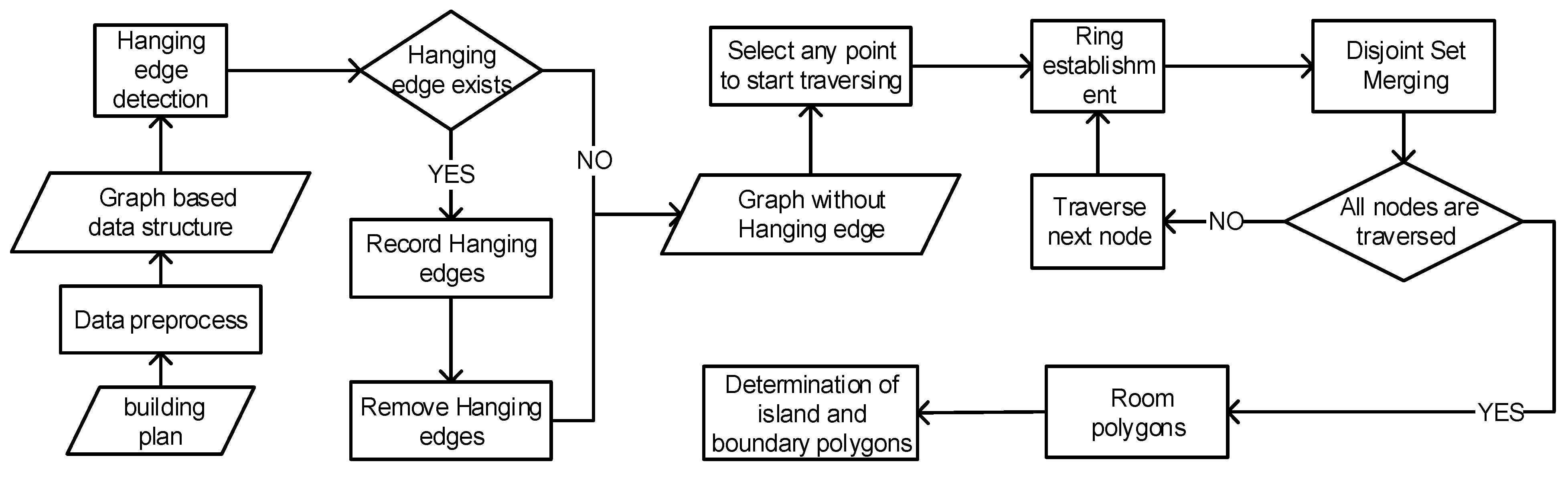
Figure 5.
The process of extracting hanging edges from building plans. (a) Rooms with hanging edges; (b) DFS traversal trees; and (c) backtracking processes.
Figure 5.
The process of extracting hanging edges from building plans. (a) Rooms with hanging edges; (b) DFS traversal trees; and (c) backtracking processes.

Figure 6.
Set merging. (a) The tree structure of sets x and y. (b) The effect of merging sets x and y.
Figure 6.
Set merging. (a) The tree structure of sets x and y. (b) The effect of merging sets x and y.

Figure 7.
Path compression. (a) Before executing . (b) After executing.

Figure 8.
Polygon extraction principle based on disjoint set.

Figure 9.
Ring formation process and adjacent edges merging.

Figure 10.
Determination of connected blocks in a building plan.

Figure 11.
Indoor space topology model and hanging edge extraction. (a) The original building plan. (b) Indoor space topological result. (c) Indoor local space with hanging edges. (d) Hanging edge extraction result.
Figure 11.
Indoor space topology model and hanging edge extraction. (a) The original building plan. (b) Indoor space topological result. (c) Indoor local space with hanging edges. (d) Hanging edge extraction result.

Figure 12.
Multi-island nesting detection. (a) Simulated building plan. (b) Extraction result.

Figure 13.
Continuous multi-island detection. (a) Complex scene test data. (b) Extraction result.


Table 1.
The topological relation table of rooms and walls.
| Room ID | Wall Lines | Room Center Coordinates | Number of Doors | Room Type |
|---|---|---|---|---|
| R1 | (E1, E3, E4, E5) | (,) | 1 | Ordinary room |
| R2 | (E0, E2, E3, E5, E6, E7, E8, E9) | (,) | 5 | Corridor |
| R3 | (E8, E10, E11, E13) | (,) | 2 | Ordinary room |
| R4 | (E9, E11, E12, E14) | (,) | 2 | Ordinary room |
| R5 | (E19) | (,) | 0 | Obstruction |
| R6 | (E15, E16, E17, E18) | (,) | 1 | Ordinary room |
Table 2.
The topological relation table of doors and rooms.
| Door ID | Wall Line | Room 1 | Room 2 |
|---|---|---|---|
| D0 | E2 | R2 | Null |
| D1 | E11 | R4 | R3 |
| D2 | E8 | R3 | R2 |
| D3 | E9 | R4 | R2 |
| D4 | E5 | R1 | R2 |
| D5 | E0 | R2 | Null |
| D6 | E15 | R6 | R2 |
Table 3.
The topological relation table of rooms and rooms.
| Room ID | Connective Relationship | Adjacent Relationship | Inclusionary Relationship |
|---|---|---|---|
| R1 | <D4, R2> | R2, Routdoor | Null |
| R2 | <D0, Routdoor>, <D5, Roudoor>, <D2, R3>, <D3, R4>, <D4, R1> | R3, R4, R1, Routdoor | R5, R6 |
| R3 | <D1, R4>, <D2, R2> | R2, R4, Routdoor | Null |
| R4 | <D1, R3>, <D3, R2> | R2, R3, Routdoor | Null |
| R5 | Null | Null | Null |
| R6 | <D6, R2> | Null | Null |
Table 4.
Initialization status of set.
| Node | … | ||||
| Parent | … | ||||
| Set | … |
Table 5.
Disjoint set initialization result.
| Edge_ID | E1′ | E3 | E4′ | E5 |
| Set | E1′ | E3 | E4′ | E5 |
Table 6.
Disjoint set query result.
| Edge_ID | E1′ | E3 | E4′ | E5 |
| Set | E5 | E5 | E5 | E5 |
Table 7.
Hanging edge extraction test in complex indoor space.
| Data | Number of Actual Hanging Edges | Number of Detected Hanging Edges | IDs of Hanging Edges | Room ID Containing Hanging Edges |
|---|---|---|---|---|
| Scene 1 | 10 | 10 | 253 < 148–151 >, 268 < 150–156 > | 58 |
| 475 < 384–386 > | 104 | |||
| 478 < 381–382 > | 105 | |||
| 621 < 618–612 > | 140 | |||
| 624 < 616–617 > | 142 | |||
| 773 < 778–779 >, 779 < 940–941 > | 183 | |||
| 773 < 813–820 >, 779 < 822–825 > | 187 |
Disclaimer/Publisher’s Note: The statements, opinions and data contained in all publications are solely those of the individual author(s) and contributor(s) and not of MDPI and/or the editor(s). MDPI and/or the editor(s) disclaim responsibility for any injury to people or property resulting from any ideas, methods, instructions or products referred to in the content. |
© 2023 by the authors. Licensee MDPI, Basel, Switzerland. This article is an open access article distributed under the terms and conditions of the Creative Commons Attribution (CC BY) license (https://creativecommons.org/licenses/by/4.0/).
Share and Cite
MDPI and ACS Style
Han, L.; Qiao, H.; Li, Z.; Liu, M.; Zhang, P. Navigation-Oriented Topological Model Construction Algorithm for Complex Indoor Space. ISPRS Int. J. Geo-Inf. 2023, 12, 248. https://doi.org/10.3390/ijgi12060248
AMA Style
Han L, Qiao H, Li Z, Liu M, Zhang P. Navigation-Oriented Topological Model Construction Algorithm for Complex Indoor Space. ISPRS International Journal of Geo-Information. 2023; 12(6):248. https://doi.org/10.3390/ijgi12060248
Chicago/Turabian StyleHan, Litao, Hu Qiao, Zeyu Li, Mengfan Liu, and Pengfei Zhang. 2023. "Navigation-Oriented Topological Model Construction Algorithm for Complex Indoor Space" ISPRS International Journal of Geo-Information 12, no. 6: 248. https://doi.org/10.3390/ijgi12060248
Note that from the first issue of 2016, this journal uses article numbers instead of page numbers. See further details here.