Abstract
Background: The application of continuum manipulators as assistive robots is discussed and tested through the use of Bendy ARM, a simple manually teleoperated tendon driven continuum manipulator prototype. Methods: Two rounds of user testing were performed to evaluate the potential of this arm to aid people living with disabilities in completing activities of daily living. Results: In the first round of user testing, 14 able-bodied subjects successfully completed the prescribed task (pick-and-place) using multiple control schemes after being given a brief introduction and one minute of practice with each scheme. In the second round of user testing, subjects () demonstrated between 29.5 and 48.9 percent improvement in completion time across twelve trials of a peg-in-hole task, and between 8.4 and 33.8 percent improvement across six trials of a task involving opening and closing a drawer. Conclusion: Based on these results, it is posited that continuum manipulators merit further consideration as a safer and more cost-effective alternative to existing commercially available assistive robotic manipulators.
1. Introduction
The use of robots in assistive technology is well-studied; numerous robotic arms for rehabilitative applications have been designed and tested to-date, and several are commercially available [1,2]. These robots are often intended to improve independence and quality of life for people who are unable to perform activities of daily living (ADLs) without additional aid. Traditional rigid-link robots have been shown to be effective at completing various ADLs in both wheelchair mounted and desktop configurations [2]. Unfortunately, most of these traditional robotic arms are prohibitively expensive, costing tens of thousands of dollars [3]. Additionally, many of these systems must incorporate sophisticated sensors and control methods in order to ensure the safety of their users [4,5]. This paper proposes an alternative platform for assistive robotics which alleviates these issues: continuum manipulators.
Of the assistive robotic arms which are currently commercially available, two of the most notable are the MANUS [6] and JACO [7] arms. MANUS and JACO are seven degree of freedom (DOF) wheelchair mounted assistive robotic manipulators (WMRM) with payload capacities of approximately 1.5 kg. MANUS uses incremental encoders for controlling position, and does not incorporate any other sensors and it can be controlled by a joystick or other user interface. Similarly, the JACO robot is controlled with a three axis joystick – different functionalities of the arm can be accessed by using pushbuttons to select between three control modes. The use of joysticks as a user input is relatively common for continuum manipulators [8,9], although other user input systems have been explored, such as optical motion tracking [10] or a six degree-of-freedom stylus [11]. Manipulators such as the MANUS and JACO demonstrate the ability of assistive robots to be used to perform various ADLs and increase quality of life for people living with disabilities [7]. We propose that continuum manipulators could accomplish the same or similar tasks at a relatively low cost and with minimal risk to the user.
Continuum manipulators are robots that lack traditional rigid segments and discrete joints. Instead, they function by bending continuously along their length, like the trunk of an elephant or the arm of an octopus. In order to achieve this bending motion, continuum manipulators are often made of soft and flexible materials subject to deformation by external forces. As such, these robots are inherently compliant, meaning they will conform to the shape of their environment [12]. The compliant nature of continuum robots allows them to accomplish tasks which their rigid counterparts are either incapable of or unsuited for, such as navigating in confined or unstructured environments (e.g., inside of a human body) and grasping fragile or awkwardly shaped objects [13,14].
The field of continuum robotics is relatively new; prior to the 1990s, only a handful of attempts had been made at designing and understanding continuum manipulators [15,16,17]. To-date, numerous possible applications have been proposed: search and rescue [18,19], radioactive waste handling [20], outer-space assistance [21], and minimally invasive surgery [22,23,24,25], among others. But while the use of continuum manipulators in minimally invasive surgery has been well explored and assessed, many other applications remain untested.
This research seeks to demonstrate the potential for a continuum robot to perform successfully as an assistive device. The nature of assistive technology requires close human–robot interaction, which makes safety of the user one of the primary concerns of the field. Continuum manipulators are designed in a way that allows them to react to obstructions without additional sensors and algorithms—if they contact an extremity, they bend to accommodate it. Because continuum manipulators do not require additional features to ensure the safety of their users, they can also be built with less complexity, and therefore at a lower cost, than traditional assistive robotic arms. However, safety of continuum manipulators is conditional on proper considerations being given for possible failure modes [26]. The application of continuum manipulators in assistive technology has been briefly explored with respect to the ADL of bathing, although no user testing of this proposal has yet been completed [27,28]. Similarly, the compliant nature of continuum arms lends them to any ADL where close human contact is necessary, such as applying lotion, scratching one’s back, combing hair, or brushing teeth.
Precise control is required to achieve many of the tasks outlined above. Position-based control is well understood for traditional rigid-link robots; the inverse kinematics problems generally have closed-form solutions that are not very computationally intensive [29]. In the case of continuum robots, the inverse kinematics problem is much more difficult, often requiring extensive mathematical models and approximations [29]. A large portion of the research on continuum manipulators to date has been devoted to the development of mathematical models for control, and several viable models have been established [29,30,31,32]. Many of these methods are computationally intensive and require precise construction and calibration of the manipulator in question [29,30]. An alternative approach to control is to allow the user to compensate for any challenges presented by the robot’s continuum structure via teleoperation.
This work presents a low-cost, tendon-driven continuum arm for experimentation and user testing. This robot, Bendy Assistive Robotic Manipulator (Bendy ARM), employs a joystick-based teleoperation system, with three novel control schemes, which are described in Section 2.1, designed to give the user complete and intuitive control over the arm. Bendy ARM is used as a prototyping platform to demonstrate potential applications of continuum robotics in assistive technology through user testing.
2. Materials and Methods
Bendy ARM consists primarily of a flexible backbone mounted on a wooden base. The backbone is divided into two sections. The first (proximal) section, closest to the base, is made of a 0.95 cm diameter piece of low density polyethylene (LDPE), segmented by six 3D-printed acrylonitrile butadiene styrene (ABS) disks (11.43 cm diameter) each spaced 7.62 cm apart (see Figure 1). Four tendons made of 50 pound test braided fishing line control each section, terminating at the last disk in the section (the disk furthest from the base of the arm). These tendons are separated by 90 and driven by 1.8 NEMA 23 stepper motors with a torque rating of 125 oz.-in. These motors decrease or increase the effective length of the tendons by coiling or uncoiling them around spools.
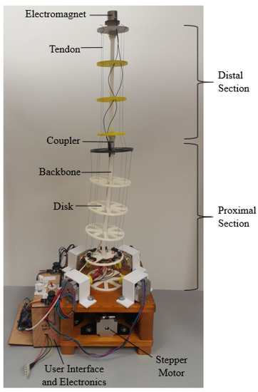
Figure 1.
Bendy ARM robot. The four stepper motors on the upper platform of the wooden base drive the distal section. The four stepper motors on the lower platform (only one can be seen in the image) drive the proximal section. The two sets of stepper motors are rotationally offset 45 from each other. All relevant files associated with the physical construction and code are available online, doi:10.17605/OSF.IO/EZFKN.
The second (distal) section consists of a 0.95 cm diameter piece of LDPE, segmented by four 3D-printed polylactic acid (PLA) disks (7.62 cm diameter) each spaced 7.62 cm apart. It is joined to the proximal section by a metal coupler. The tendons of the distal section also run though the disks of the proximal section, such that each disk in the proximal section has eight tendons running through it, whereas each disk in the distal section has four tendons running through it.
In order to produce a continuous bending motion, the tendons of the robot are actuated in pairs. Any two tendons separated by 180 are driven in lockstep, such that when one tendon shortens, the other lengthens by the same amount. Each tendon pair is driven by a pair of stepper motors in order to provide the tendon tension necessary to position the manipulator and carry a load. This lockstep actuation produces a bending motion with approximately constant curvature along the plane defined by the pair of tendons. Each stage has two pairs of tendons, offset from each other by 90. Simultaneously actuating both pairs of tendons by different amounts effectively allows the robot to reach any position along the constant curvature arc of the segment. Adding the motion of the second stage further increases the range of motion of the robot and greatly increases the number of accessible positions. The result is an eight DOF robot with a maximum reach that is roughly defined by a sphere of radius equal to the length of the two concatenated backbone segments. The accessible positions of the manipulator are then approximately defined by the overlap between the spherical workspaces of the two manipulator segments. The proximal section is 41.28 cm long and the distal section is 29.21 cm long, yielding a total length, or workspace radius, of approximately 70 cm. However, many of the locations within this sphere are inaccessible due to self-intersection or impractically tight curvature requirements.
The stepper motors are driven by DRV8825 high-current stepper-motor drivers. The eight DRV8825s are controlled by an Arduino Mega, which also handles inputs from the control panel and the eight limit switches seen in Figure 2. The arm is powered by a 12V 30A DC switching power supply. All of these components are low-cost and accessible, which drives the total component cost of Bendy ARM below $550. Although this robot is only a prototyping platform and many of the components are not suitable for commercial use, the production cost of a commercial model would still be relatively low (compared to existing assistive robots). This cost reduction could help increase access to assistive robots and potentially improve quality of life for people of modest incomes living with disabilities.
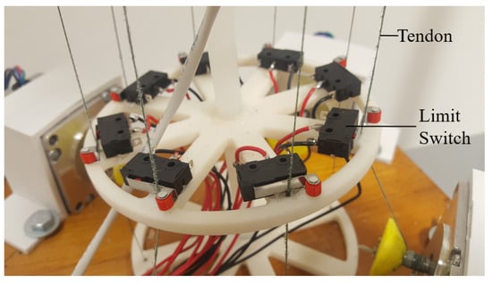
Figure 2.
Slack-eliminating mechanism for Bendy ARM.
It is worth noting that the two backbone sections of the arm are mechanically coupled; adjusting the tendon lengths in one section inherently affects the position of the other. This type of motion is particularly obvious when adjusting the distal segment and leaving the proximal segment stationary. When the distal segment tendons are actuated, their load is transferred to the entire backbone of the robot, intrinsically changing the position of the proximal segment. The mechanical coupling of the robot can also be observed if the proximal segment is actuated while the distal segment is kept stationary. As the bottom segment moves under the top stage, the static top stage tendons pull back against this motion, causing the top segment to curl in the opposite direction. As such, the top stage curls relative to the bottom stage naturally to maintain a constant global orientation. The mechanical coupling of the robot is a drawback because it makes control less intuitive and control schemes more difficult to implement.
2.1. Control Schemes
Bendy ARM is teleoperated via a user interface connected directly to the robot (see Figure 3). The control panel consists of two joysticks and three switches. The user is able to operate the robot using one of three control schemes: Dual-Joystick, Single-Joystick Segmented, and Single-Joystick Compensative. Each of these control schemes are open-loop, making use of direct user observation and manipulation for course correction. This helps compensate for the effects of payload and other positional errors without the use of a more sophisticated, computationally intensive control algorithm.
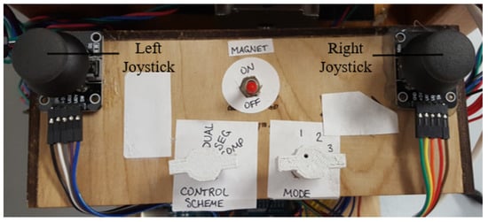
Figure 3.
User interface for Bendy ARM.
In the Dual-Joystick control scheme (henceforth referred to as Dual control), the left joystick controls the proximal section and the right joystick controls the distal section. The inputs on the x and y axes of the joysticks are directly mapped to the x and y actuator pairs of each segment. When either joystick is pushed in any direction, the corresponding section will bend in that direction, relative to the position of its base. No attempt at decoupling the two segments is made in this scheme, so adjusting the distal section affects the position of the proximal section, and vice versa. The speed at which the section moves is proportional to the magnitude of the joystick’s displacement.
In the Single-Joystick Segmented control scheme (henceforth referred to as Segmented control), only the right joystick is used. One advantage of this control scheme is that it allows for users with use of only one hand to operate the robot. The user can select between three different control modes using the ‘Mode’ switch. In Mode 1, pushing the joystick in any direction will bend both sections simultaneously in that direction such that the whole arm moves as a single unit. This whole-arm movement is useful for gross positioning of the arm. It can also be achieved in Dual-Joystick mode by pushing both joysticks in the same direction at the same time. In Mode 2, the joystick controls only the distal section. In Mode 3, the joystick controls only the proximal section. Again, no attempt is made at decoupling the sections.
In the Single-Joystick Compensative control scheme (henceforth referred to as Compensative control), again, only the right joystick is used, with two different control modes available via the ‘Mode’ switch. Mode 1 is the same as in Segmented control, allowing for whole-arm movement. In Mode 2, the joystick controls the proximal and distal sections. When the joystick is moved in any direction, the distal section will move at a given speed in the corresponding direction, while the proximal section moves at half of that speed in the opposite direction. The opposing motion of the proximal section is meant to compensate for the mechanical coupling of the two sections. Although it does not yield perfect compensation, it does enable the distal section to be moved nearly independently of the proximal (See this video of an inexperienced user driving the manipulator in Compensative control mode, https://osf.io/4upxa/.). This is useful when attempting fine resolution positioning with the distal end of the arm, since the user can control the distal section without having to consciously compensate for the displacement of the proximal section.
Clicking down on the right joystick (or either joystick in Dual control) causes the robot to return to its ‘home’ position, i.e., pointing straight upwards (the robot is shown in its home position in Figure 1). This mechanism will henceforth be referred to as the re-centering protocol. During regular operation, the micro-controller keeps track of the robot’s position by counting the number of steps sent to each stepper motor. When the re-centering protocol is executed, each stepper motor is driven back to its starting position (which means that the robot must be started in its home position for the re-centering protocol to work properly). The limit switches attached to the robot’s second disk (see Figure 2) serve the purpose of removing any slack that has developed in the tendons during operation. They are mounted such that the switch is depressed (closed) only when the tendon is taut. After the re-centering protocol is executed, if any of the switches are open, the motor controlling the corresponding tendon will coil that tendon until the switch is closed.
2.2. User Testing
User testing of continuum robots is largely unexplored; however, a few studies have investigated how people interface with and use these arms. Csencsits et al. [8] describe various methods for user control of the OctArm and Air-Octor continuum manipulators which were implemented and qualitatively tested. Gomer et al. [18] describe a virtual reality environment that was used to evaluate operator skill with a continuum arm; users were asked to grasp an object in the virtual space using the robot. While this study demonstrated some degree of skill acquisition in operators, the tests were performed purely in a virtual space and the primary goal of the study was to validate the virtual environment as a testing and training platform. Finally, McMahan et al. [14] describe field tests of the user-operated OctArm continuum manipulator, demonstrating the ability of the manipulator to stack and unstack cones, grasp spheres, and grasp objects submerged in water. While these studies all involve user testing, they are generally qualitative in their assessments, and focus more on the robots than on the humans operating them.
This lack of quantified user testing presents as a noticeable gap in the literature, since assistive robotics requires a direct interaction between humans and robots [33]. Therefore, one aim of this study was to obtain and analyze quantitative data on user testing with our robot. Specifically, we wanted to determine which control scheme allows for the most effective and intuitive control of Bendy ARM, as well as how quickly users can learn to effectively operate the robot. In order to address these goals, two rounds of user testing were carried out. Prior to the conduct of any user testing, this project was reviewed by the UW-Stout Institutional Review Board and was determined to be exempt under Category of the Federal Exempt Guidelines. The specific procedures used for each round of user testing are described below.
2.2.1. Round One
In Round One of testing, 14 able-bodied users—eight males and six females between 16 and 58 years old—were introduced to three different control schemes and asked to complete a given task three separate times, using each control scheme once. The majority of the users had never been introduced to the prototype, or continuum arms in general, so the task was designed to be simple. The setup consisted of a metal nut placed straight out from the left side of the robot’s wooden base, and a cup secured at a position off the back right foot of the base (see Figure 4a,b). The task itself entailed simply retrieving the nut using the electromagnet attached to the end of the manipulator (see Figure 1) and dropping it into the cup on the other side of the robot’s base.
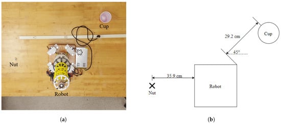
Figure 4.
Configuration used in Round One of user testing. (a) Photograph of setup. (b) Diagram of setup (not to scale).
The experimental procedure began by introducing the three control schemes one at a time, starting with a demonstration, and followed by allowing a one-minute practice period using the specific control scheme. The order in which the control schemes were introduced and used in trials was systematically varied for each user. After introducing all three control schemes, the task was revealed and explained. Data collection then began with the timed trials. The user was asked to complete the task described above three times, once with each control scheme. The order of the control schemes used for the three trials was the same as the order in which they were introduced. The time required to complete each trial was recorded, beginning on a start command from the proctor and ending when the electromagnet was switched off to drop the nut into the target cup. The user was allowed to execute the re-centering protocol and ‘start over’ if desired, but the timer did not stop until they completed the task (the same was true for all tests conducted for this study). Notes were also taken on the user’s performance as a means of qualitative analysis.
After completing the final trial, the user was debriefed and given a short survey. The survey asked them to rank the three control schemes based on intuitiveness. It also asked for the user’s age as well as an indication of how much joystick experience they had, such as regularly playing video games, as there is some evidence that this experience positively influences robot control performance [34]. These questions served as a control for confounding variables introduced by each user. Additionally, subjects were asked to provide general feedback on their experience with the robot, which was taken into consideration when evaluating their results (A copy of the survey instrument can be found at https://osf.io/43btp/).
2.2.2. Round Two
The second round of user testing entailed multiple trials of two different tasks to evaluate how user performance improved over time. All three of the subjects involved in Round Two of testing had already participated in Round One and were selected for further participation at random. The Compensative control scheme – determined by Round One of user testing to be the most effective (discussed further in the following section) – was used for all trials. Testing took place over a span of three days. On the first two days, both tasks were completed three times each day for a total of six trials of each task. On the third day, each user performed the first task an additional six times. The specifications of the two tasks – the peg-in-hole task and the drawer task – are detailed below.
The peg-in-hole task was designed to test the user’s ability to fine-tune the position of the robot’s end-effector. Two pegboards were used for this task, each with a 2 × 4 grid of diameter holes. They were placed symmetrically on the left and right sides of the robot (see Figure 5). The task itself consisted of using the robot and attached electromagnet to move metal bolts from one hole to another. First, the user was required to move a bolt from one hole to a different hole on the same board. Then, they moved a second bolt from a hole on the first board to a hole on the second board. The starting and target holes were systematically varied for every trial to ensure that each trial was different but had the same level of difficulty. Introducing variation in each trial was important for ensuring that any measured improvements in task performance were the result of increased proficiency in controlling the robot, rather than memorizing a systematic strategy for accomplishing one invariant task.
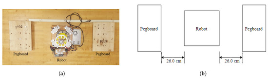
Figure 5.
Configuration used in Round Two of user testing for the Peg-in-hole task. (a) Photograph of setup. (b) Diagram of setup (not to scale).
The drawer task was more challenging but more closely simulated an activity of daily living (ADL) for which this type of robot could potentially be used. For this task, the user was asked to open a drawer, remove a metal nut from inside, drop the nut into a cup on the opposite side of the robot, pick up a second nut, place the second nut back in the drawer, and finally close the drawer. A metal washer was affixed to the plastic drawer so it could be opened using the electromagnet attached to the end of the robot.
There are four different configurations for the drawer task that maintain an equal level of difficulty across trials (see Figure 6). Two of these configurations are situated off the back right foot of the robot’s base, and the other two are arranged symmetrically off the back left foot of the base. For the two different configurations on each side, the set of drawers faces either towards the user or towards the center of the testing area.
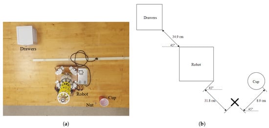
Figure 6.
Configuration used in Round Two of user testing for the Drawer task. One of four possible configurations for this task is shown. (a) Photograph of setup. (b) Diagram of setup (not to scale).
3. Results
Table 1 shows the results from Round One of user testing. On average, users were able to complete the given task most quickly using Compensative control, followed by Dual control and then Segmented control. The standard deviations for these data are relatively large, as users demonstrated a wide range of skill levels when using the robot. Data also showed that age and joystick experience did not correlate with completion time.

Table 1.
Results from Round One of User Testing for users. The ‘Average Intuition Ranking’ column represents an average of all of the intuition rankings provided for each control scheme, where a ranking of ‘1’ indicated that it was the most intuitive of the 3 control schemes and a ranking of ‘3’ indicated that it was the least intuitive.
Figure 7 shows a histogram of completion times for each control scheme. It can be seen that users were able to complete the task in under 90 seconds using Compensative control in all but one case, where a user took 240.6 seconds to complete the task. In contrast, a non-trivial number of users required more than 90 seconds to complete the task for both Dual and Segmented control (4 and 5 users, respectively). This histogram provides support for the claim that subjects were most effective using Compensative control, despite large standard deviations in the data.
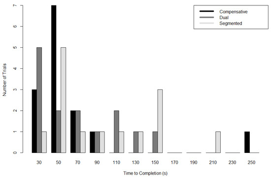
Figure 7.
Histogram from Round One of user testing.
Examining the average intuition rankings from Table 1, it can be seen that users rated Compensative control as most intuitive, followed by Dual control and then Segmented control. This result further supports Compensative control as the superior of the three control schemes.
Based on observations made during the trials, as well as qualitative feedback from the users, it is suspected that Compensative control imposes the lowest cognitive load of the three control schemes, since its second mode automatically compensates for the arm’s mechanical coupling, allowing the user to commit more mental energy to other nuances of the task. However, it should be noted that the automation of a control process means that the user has less control over how the robot moves. In this case, that tradeoff was beneficial; however, shifting too much control from the user to the control system could potentially decrease the overall functionality of the system. This statement leads to a fundamental question of whether this manipulator is better suited for autonomous control or teleoperation; an attempt to determine an answer to this question does not fall within the scope of this paper, but it is certainly worth examining in future research.
Table 2 shows the results from Round Two of user testing. It can be seen that for both the peg-in-hole and the drawer tasks, all three users were able to complete the task more quickly, on average, in the last session than the first session. In most cases, these improvements were considerable, with some nearing fifty percent. This result indicates that users consistently are able to substantially increase their proficiency using Bendy ARM with a relatively low amount of practice (the total amount of time spent using the robot between the first and last sessions was less than one hour per user). The significance of this test is that it demonstrates the potential of a continuum manipulator to be effectively used in completing ADLs without requiring a large amount of training.
Table 2.
Results from Round Two of user testing. (a) Peg-in-hole task. Each session consisted of three consecutive trials, with the exception of the third session, which consisted of six consecutive trials. The percent improvement is from Session One to Session Three. (b) Drawer task. Each session consisted of three consecutive trials.
Figure 8 shows results from Round Two of user testing on a trial-by-trial basis. Note that Figure 8a, depicts a significant drop in average completion time between the first six trials and the last six trials. Additionally, there is much less trial-to-trial variation in the last six trials than the first six trials. These trends may suggest that users spend a certain amount of time learning how to complete a task before they achieve proficiency, at which point they are able to complete the task relatively quickly on a consistent basis.
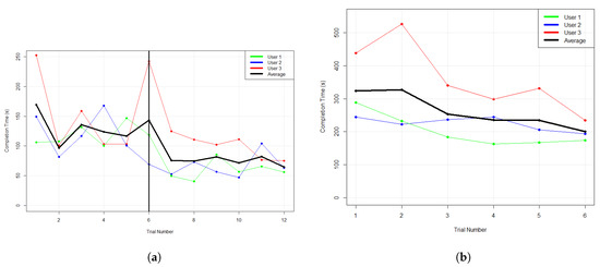
Figure 8.
Results from Round Two of user testing. (a) Peg-in-hole task. The bolded vertical line marks the end of the second session of testing. (b) Drawer task.
In contrast to the segmented improvement trend depicted in Figure 8a, a more steady downward trend in completion time is seen in Figure 8b. We expect that this disparity is a result of the dissimilarity of the two tasks. The peg-in-hole task (Figure 9a) was a relatively simple task, involving a pick-and-place movement similar to the one used in Round One of user testing, in which all of the subjects of Round Two had previously participated. Therefore, users were able to achieve a basic level of familiarity with the task relatively quickly (after one trial), at which point they required practice before they could learn to accomplish the task proficiently. In contrast, the drawer task was a novel task which was relatively complicated, requiring users to manipulate the arm into a specific shape in order to open the drawer (see Figure 9b). As a result, users gained a considerable amount of insight on how to best complete the task with each trial, allowing them to improve consistently. We suspect that, with additional trials, completion time would continue to decrease before leveling out, similarly to what was observed with the peg-in-hole task. An expanded study with a larger sample size would allow for a deeper investigation of these preliminary results.
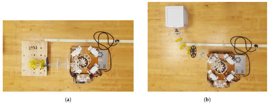
Figure 9.
(a) The simple configuration required for the peg-in-hole task and (b) the complex configuration required for accomplishing the drawer task.
3.1. Additional Applications
Several other user-based tests for Bendy ARM were proposed which provide insight into the type of tasks that a simple continuum robot may be able to accomplish. The first of these tests was designed to imitate the ADL of bathing, and involved using an eraser attached to the end of the robot to clean a whiteboard. The motions involved in performing this task closely resemble the motions required to scrub a part of the body, such as the back. The advantage of this task is that it provides an objective performance measure (percentage of whiteboard erased). We tested this task with the current prototype and found that it was exceedingly difficult due to the challenge of maneuvering the end effector along the surface of a plane using the current control schemes. A more sophisticated control scheme could potentially be developed to make this type of motion more efficient and intuitive.
Another application that was considered was turning a light switch on and off. Several trials revealed that turning off the lights was a trivial task while turning them back on proved to be very difficult. This disparity in difficulty was largely due to the different arm configurations required to perform each subtask, and shows that just because one aspect of a task is simple does not guarantee that other aspects will be.
Another proposed application involved hanging a set of keys on a hook mounted to the wall and then removing them from the hook. Even with the robot in its current development state, this task was fairly easy to accomplish.
3.2. Limitations and Future Research
Bendy ARM is a prototype, not a final product, and therefore exhibits a number of limitations that need to be addressed. One of the robot’s major limitations is the material used for its backbone—LDPE. While this material’s flexibility allowed for a large range of motion, repeated deformation over time fatigued the material to the point that the arm tended to remain slightly bent in the direction it was last extended after re-centering. Other, more suitable backbone materials may be better suited for long-term use.
The mechanical coupling of the robot’s two segments is another issue which needs to be addressed. Although this issue was partially remedied through the Compensated control scheme, it still had a somewhat detrimental effect upon the user’s ability to control the robot, and would require a more robust solution before the robot could be fully effective. One possibility is to route the four tendons that actuate the distal segment of the manipulator through Bowden cables such that they bypass the routing disks of the proximal segment. Thus reducing the influence of these tendons on the motion of the proximal segment. Additionally, the manipulator would likely exhibit greater controllability if damping was added to smooth out instabilities introduced by the manipulator’s inertia or external excitations.
Finally, the robot has a relatively small payload capacity (less than 0.5 kg). In practice, this limits the tasks that can be performed by the device. However, tasks such as small object retrieval or button pressing are within the device’s capabilities. A video showing the device performing some example manipulation tasks is available online (https://youtu.be/W6tjoNSmKyE). Increasing the payload capacity may be achievable through the use of non-hobbyist-grade materials, but limited payload capacity is a general problem for continuum manipulators due to their non-rigid structures, and a solution to this issue would have a large impact on increasing the capability of these types of robots. Relatedly, fitting the manipulator with a capable gripper would improve performance. A variety of suitable soft grippers which could be integrated with a continuum manipulator have been described in the literature [27,35,36,37,38,39,40,41].
Beyond the limitations of the robot itself, the user testing performed in this research should also be expanded upon with a larger, more diverse user sample, particularly for Round Two testing. The most obvious discrepancy is that there were no end users (people with disabilities who have loss of upper limb function) involved in the testing. To allow for these users to test the robot, the control panel would need to be updated in order to accommodate their disabilities, most likely on a case-by-case basis. Additionally, it would be useful to compare the performance of the Bendy ARM with that of a commercially available rigid-link arm. If user testing could show that a continuum arm can perform just as well or better than a traditional rigid-link arm, a strong case would be made for their use as assistive robots. Finally, a formalized metric should be employed to provide a standardized comparison between comparable manipulators, such as the NASA-Task Load Index [42,43].
4. Discussion and Conclusions
Bendy ARM is a tendon-driven continuum manipulator which has the potential to be used as an assistive robot, aiding people living with disabilities in the independent completion of ADLs. Continuum manipulators may be better suited to assistive technology than other commercially available robots such as MANUS Arm and JACO Arm due to their inherent safety and relatively low cost. User testing has shown that Bendy ARM can be used to perform multiple tasks (pick-and-place, peg-in-hole, opening and closing drawers) with minimal training. Additionally, this research has yielded quantitative evidence suggesting that users demonstrate significant improvement in using Bendy ARM in a relatively short amount of time. Future research involving continuum manipulators should include user testing with subjects from the target population, as well as statistical comparisons between these manipulators and commercially availably WMRMs, which could be accomplished by having subjects perform the same task using each robot. The findings of this research indicate that there is a strong possibility that continuum manipulators can be applied successfully to the field of assistive technology in the future.
Author Contributions
Conceptualization, R.C., M.R., M.K. and D.R.B.; methodology, R.C., M.R., M.K. and D.R.B.; software, R.C., M.R. and M.K.; formal analysis, R.C., M.R., M.K. and D.R.B.; investigation, R.C., M.R., M.K. and D.R.B.; writing—original draft preparation, R.C., M.R., M.K. and D.R.B.; writing—review and editing, R.C. and D.R.B.; supervision, D.R.B.; project administration, D.R.B.; funding acquisition, D.R.B.
Funding
This research was funded by the National Science Foundation under Grant No. CNS-1560219. Any opinions, findings, and conclusions or recommendations expressed in this material are those of the authors and do not necessarily reflect the views of the National Science Foundation.
Conflicts of Interest
The authors declare no conflict of interest.
References
- Romer, G.; Stuyt, H.J.; Peters, A. Cost-savings and economic benefits due to the assistive robotic manipulator (ARM). In Proceedings of the 9th International Conference on Rehabilitation Robotics (ICORR 2005), Chicago, IL, USA, 28 June–1 July 2005; pp. 201–204. [Google Scholar]
- Chung, C.S.; Wang, H.; Cooper, R.A. Functional assessment and performance evaluation for assistive robotic manipulators: Literature review. J. Spinal Cord Med. 2013, 36, 273–289. [Google Scholar] [CrossRef] [PubMed]
- Allin, S.; Eckel, E.; Markham, H.; Brewer, B.R. Recent trends in the development and evaluation of assistive robotic manipulation devices. Phys. Med. Rehabil. Clin. N. Am. 2010, 21, 59–77. [Google Scholar] [CrossRef] [PubMed]
- Dellon, B.; Matsuoka, Y. Prosthetics, exoskeletons, and rehabilitation [grand challenges of robotics]. IEEE Robot. Autom. Mag. 2007, 14, 30–34. [Google Scholar] [CrossRef]
- Hägele, M.; Schaaf, W.; Helms, E. Robot assistants at manual workplaces: Effective co-operation and safety aspects. In Proceedings of the 33rd ISR (International Symposium on Robotics), Stockholm, Sweden, 7–11 October 2002; pp. 7–11. [Google Scholar]
- Driessen, B.; Evers, H.; v Woerden, J. MANUS—A wheelchair-mounted rehabilitation robot. Proc. Inst. Mech. Eng. Part H J. Eng. Med. 2001, 215, 285–290. [Google Scholar] [CrossRef] [PubMed]
- Maheu, V.; Archambault, P.S.; Frappier, J.; Routhier, F. Evaluation of the JACO robotic arm: Clinico-economic study for powered wheelchair users with upper-extremity disabilities. In Proceedings of the 2011 IEEE International Conference on Rehabilitation Robotics, Zurich, Switzerland, 29 June–1 July 2011; pp. 1–5. [Google Scholar]
- Csencsits, M.; Jones, B.A.; McMahan, W.; Iyengar, V.; Walker, I.D. User interfaces for continuum robot arms. In Proceedings of the 2005 IEEE/RSJ International Conference on Intelligent Robots and Systems (IROS 2005), Edmonton, AB, Canada, 2–6 August 2005; pp. 3123–3130. [Google Scholar]
- Orekhov, A.L.; Black, C.B.; Till, J.; Chung, S.; Rucker, D.C. Analysis and Validation of a Teleoperated Surgical Parallel Continuum Manipulator. IEEE Robot. Autom. Lett. 2016, 1, 828–835. [Google Scholar] [CrossRef]
- Travaglini, T.A.; Swaney, P.J.; Weaver, K.D.; Webster, R.J. Initial Experiments with the Leap Motion as a User Interface in Robotic Endonasal Surgery. In Robotics and Mechatronics: Proceedings of the 4th IFToMM International Symposium on Robotics and Mechatronics; Zeghloul, S., Laribi, M., Gazeau, J.-P., Eds.; Springer: Cham, Switzerland, 2016; Volume 37, pp. 171–179. [Google Scholar] [CrossRef]
- Burgner, J.; Rucker, D.C.; Gilbert, H.B.; Swaney, P.J.; Russell, P.T.; Weaver, K.D.; Webster, R.J. A Telerobotic System for Transnasal Surgery. IEEE/ASME Trans. Mechatron. 2014, 19, 996–1006. [Google Scholar] [CrossRef] [PubMed]
- Robinson, G.; Davies, J.B.C. Continuum robots-a state of the art. In Proceedings of the 1999 IEEE International Conference on Robotics and Automation, Detroit, MI, USA, 10–15 May 1999; Volume 4, pp. 2849–2854. [Google Scholar]
- Walker, I.D. Continuous backbone “continuum” robot manipulators. ISRN Robot. 2013, 2013, 726506. [Google Scholar] [CrossRef]
- McMahan, W.; Chitrakaran, V.; Csencsits, M.; Dawson, D.; Walker, I.D.; Jones, B.A.; Pritts, M.; Dienno, D.; Grissom, M.; Rahn, C.D. Field trials and testing of the OctArm continuum manipulator. In Proceedings of the 2006 IEEE International Conference on Robotics and Automation (ICRA), Orlando, FL, USA, 15–19 May 2006; pp. 2336–2341. [Google Scholar]
- Anderson, V.C.; Horn, R.C. Tensor Arm Manipulator. U.S. Patent 3,497,083, 24 February 1970. [Google Scholar]
- Hirose, S.; Cave, P.; Goulden, C. Biologically Inspired Robots: Serpentile Locomotors and Manipulators; Oxford University Press: Oxford, UK, 1993. [Google Scholar]
- Wilson, J.F.; Mahajan, U. The mechanics and positioning of highly flexible manipulator limbs. J. Mech. Transm. Autom. Des. 1989, 111, 232–237. [Google Scholar] [CrossRef]
- Gomer, J.A.; Moore, K.S.; Crisler, M.C.; Kwoka, M.J.; Pagano, C.C. VRML Use for Iterative Usability Testing of User Interfaces: A Novel Continuum Robotic Limb Example. Proc. Hum. Factors Ergon. Soc. Annu. Meet. 2006, 50, 2187–2191. [Google Scholar] [CrossRef]
- Tsukagoshi, H.; Kitagawa, A.; Segawa, M. Active hose: An artificial elephant’s nose with maneuverability for rescue operation. In Proceedings of the 2001 ICRA IEEE International Conference on Robotics and Automation, Seoul, Korea, 21–26 May 2001; Volume 3, pp. 2454–2459. [Google Scholar]
- Immega, G.; Antonelli, K. The KSI tentacle manipulator. In Proceedings of the 1995 IEEE International Conference on Robotics and Automation, Nagoya, Japan, 21–27 May 1995; Volume 3, pp. 3149–3154. [Google Scholar]
- Mehling, J.S.; Diftler, M.A.; Chu, M.; Valvo, M. A minimally invasive tendril robot for in-space inspection. In Proceedings of the First IEEE/RAS-EMBS International Conference on Biomedical Robotics and Biomechatronics (BioRob 2006), Pisa, Italy, 20–22 February 2006; pp. 690–695. [Google Scholar]
- Narazaki, K.; Oleynikov, D.; Stergiou, N. Robotic surgery training and performance. Surg. Endosc. Other Interv. Tech. 2006, 20, 96–103. [Google Scholar] [CrossRef]
- Penning, R.S.; Jung, J.; Borgstadt, J.A.; Ferrier, N.J.; Zinn, M.R. Towards closed loop control of a continuum robotic manipulator for medical applications. In Proceedings of the 2011 IEEE International Conference on Robotics and Automation (ICRA), Shanghai, China, 9–13 May 2011; pp. 4822–4827. [Google Scholar]
- Yoon, H.S.; Oh, S.M.; Jeong, J.H.; Lee, S.H.; Tae, K.; Koh, K.C.; Yi, B.J. Active bending endoscope robot system for navigation through sinus area. In Proceedings of the 2011 IEEE/RSJ International Conference on Intelligent Robots and Systems (IROS), San Francisco, CA, USA, 25–30 September 2011; pp. 967–972. [Google Scholar]
- Berg, D.R.; Li, P.Y.; Erdman, A.G. Achieving dexterous manipulation for minimally invasive surgical robots through the use of hydraulics. In Proceedings of the 2012 ASME Dynamic Systems and Control Conference, Fort Lauderdale, FL, USA, 17–19 October 2012. [Google Scholar] [CrossRef]
- Abidi, H.; Cianchetti, M. On Intrinsic Safety of Soft Robots. Front. Robot. AI 2017, 4. [Google Scholar] [CrossRef]
- Manti, M.; Pratesi, A.; Falotico, E.; Cianchetti, M.; Laschi, C. Soft assistive robot for personal care of elderly people. In Proceedings of the 2016 6th IEEE International Conference on Biomedical Robotics and Biomechatronics (BioRob), Singapore, 26–29 June 2016; pp. 833–838. [Google Scholar]
- Ansari, Y.; Manti, M.; Falotico, E.; Mollard, Y.; Cianchetti, M.; Laschi, C. Towards the development of a soft manipulator as an assistive robot for personal care of elderly people. Int. J. Adv. Robot. Syst. 2017, 14, 1729881416687132. [Google Scholar] [CrossRef]
- Webster, R.J., III; Jones, B.A. Design and kinematic modeling of constant curvature continuum robots: A review. Int. J. Robot. Res. 2010, 29, 1661–1683. [Google Scholar] [CrossRef]
- Rucker, D.C.; Webster, R.J., III. Statics and dynamics of continuum robots with general tendon routing and external loading. IEEE Trans. Robot. 2011, 27, 1033–1044. [Google Scholar] [CrossRef]
- Camarillo, D.B.; Carlson, C.R.; Salisbury, J.K. Configuration tracking for continuum manipulators with coupled tendon drive. IEEE Trans. Robot. 2009, 25, 798–808. [Google Scholar] [CrossRef]
- Chirikjian, G.S.; Burdick, J.W. A modal approach to hyper-redundant manipulator kinematics. IEEE Trans. Robot. Autom. 1994, 10, 343–354. [Google Scholar] [CrossRef]
- Coulson, R.; Kirkpatrick, M.; Robinson, M.; Donahue, M.; Berg, D.R. User Testing of a Continuum Manipulator for Assistive Technology. engrXiv 2018. [Google Scholar] [CrossRef]
- Lynch, J.; Aughwane, P.; Hammond, T.M. Video games and surgical ability: A literature review. J. Surg. Educ. 2010, 67, 184–189. [Google Scholar] [CrossRef]
- Mutlu, R.; Alici, G.; in het Panhuis, M.; Spinks, G.M. 3D Printed Flexure Hinges for Soft Monolithic Prosthetic Fingers. Soft Robot. 2016, 3, 120–133. [Google Scholar] [CrossRef]
- Al Abeach, L.A.; Nefti-Meziani, S.; Davis, S. Design of a Variable Stiffness Soft Dexterous Gripper. Soft Robot. 2017, 4, 274–284. [Google Scholar] [CrossRef]
- Zhang, H.; Kumar, A.S.; Fuh, J.Y.H.; Wang, M.Y. Design and Development of a Topology-Optimized Three-Dimensional Printed Soft Gripper. Soft Robot. 2018, 5. [Google Scholar] [CrossRef] [PubMed]
- Wang, W.; Ahn, S.H. Shape Memory Alloy-Based Soft Gripper with Variable Stiffness for Compliant and Effective Grasping. Soft Robot. 2017, 4, 379–389. [Google Scholar] [CrossRef] [PubMed]
- Wei, Y.; Chen, Y.; Ren, T.; Chen, Q.; Yan, C.; Yang, Y.; Li, Y. A Novel, Variable Stiffness Robotic Gripper Based on Integrated Soft Actuating and Particle Jamming. Soft Robot. 2016, 3, 134–143. [Google Scholar] [CrossRef]
- Nasab, A.M.; Sabzehzar, A.; Tatari, M.; Majidi, C.; Shan, W. A Soft Gripper with Rigidity Tunable Elastomer Strips as Ligaments. Soft Robot. 2017, 4, 411–420. [Google Scholar] [CrossRef] [PubMed]
- Liu, C.H.; Chen, T.L.; Chiu, C.H.; Hsu, M.C.; Chen, Y.; Pai, T.Y.; Peng, W.G.; Chiang, Y.P. Optimal Design of a Soft Robotic Gripper for Grasping Unknown Objects. Soft Robot. 2018, 5, 452–465. [Google Scholar] [CrossRef] [PubMed]
- Hart, S.G.; Staveland, L.E. Development of NASA-TLX (Task Load Index): Results of empirical and theoretical research. Adv. Psychol. 1988, 52, 139–183. [Google Scholar] [CrossRef]
- Hart, S.G. NASA-task load index (NASA-TLX); 20 years later. Proc. Hum. Factors Ergon. Soc. Annu. Meet. 2006, 50, 904–908. [Google Scholar] [CrossRef]
© 2019 by the authors. Licensee MDPI, Basel, Switzerland. This article is an open access article distributed under the terms and conditions of the Creative Commons Attribution (CC BY) license (http://creativecommons.org/licenses/by/4.0/).