Article

Computational Systems Design of Low-Cost Lightweight Robots

by
Akhil Sathuluri
*,†,
Anand Vazhapilli Sureshbabu
,
Jintin Frank
,
Maximilian Amm
and
Markus Zimmermann
Robot Systems Group, Laboratory for Product Development and Lightweight Design, TUM School of Engineering and Design, Technical University of Munich, 85748 Munich, Germany
*
Author to whom correspondence should be addressed.
These authors contributed equally to this work.
Robotics 2023, 12(4), 91; https://doi.org/10.3390/robotics12040091
Submission received: 6 April 2023 / Revised: 8 June 2023 / Accepted: 12 June 2023 / Published: 25 June 2023
(This article belongs to the Special Issue New Trends in Robotics and Mechatronic Technologies)

Abstract

:
With the increased demand for customisation, developing task-specific robots for industrial and personal applications has become essential. Collaborative robots are often preferred over conventional industrial robots in human-centred production environments. However, fixed architecture robots lack the ability to adapt to changing user demands, while modular, reconfigurable robots provide a quick and affordable alternative. Standardised robot modules often derive their characteristics from conventional industrial robots, making them expensive and bulky and potentially limiting their wider adoption. To address this issue, the current work proposes a top-down multidisciplinary computational design strategy emphasising the low cost and lightweight attributes of modular robots within two consecutive optimisation problems. The first step employs an informed search strategy to explore the design space of robot modules to identify a low-cost robot architecture and controller. The second step employs dynamics-informed structural optimisation to reduce the robot’s net weight. The proposed methodology is demonstrated on a set of example requirements, illustrating that (1) the robot modules allow exploring non-intuitive robot architectures, (2) the structural mass of the resulting robot is 16 % lower compared to a robot designed using conventional aluminium tubes, and (3) the designed modules ensure the physical feasibility of the robots produced.

1. Introduction

Current industrial robots make automation economical by providing reliable performance for high-volume production over long timescales. However, due to the ongoing trend towards mass customisation, specialised industrial robots are often purchased and set up for low-volume processes, raising the overall cost of operation. Furthermore, conventional industrial robots are bulky machines that are not well suited for human-in-loop operations.
Moreover, the standards ISO 12018 [1] and ISO 15066 [2] provide guidelines enabling robots to work alongside humans within a shared workspace. Several safety features such as limited velocity and torque of the robot, hand-guided operation, safety rated stop, separation monitoring, etc., have enabled collaborative robots to replace industrial robots in human-centric tasks such as machine tending, sorting, and assembly [3]. A detailed discussion on the safety and implementation of collaborative robots and experimentation is presented in [4]. Despite their strong emphasis on safety, the fixed architecture of this class of robots limits their ability to adapt to a new task [5].
Modular robots, on the other hand, can adapt to changing user needs, offering an alternative to conventional fixed architecture robots. Additionally, reconfigurability unlocks the potential to realise non-intuitive kinematic architectures by spanning a vast design space with a wide range of interchangeable robot configurations. The work undertaken in [6] explores the design of cost-effective modules and standardised interfaces, while the modelling of human safety in the presence of reconfigurable robots is presented in [7]. However, such robots inherit characteristics such as high gear ratio joints, solid metal bodies, etc., from conventional industrial robots, increasing their weight, cost, and complexity. Modular robotic kits (Robot modules from Keyi robotics), on the other hand, offer a simple and user-friendly interface to build robots. Such modules, however, are limited to creating robotic toys and lack the accuracy and stiffness required in an industrial setting. A wider adoption of reconfigurable robots in the home, healthcare, and last-mile delivery sectors can be made possible by bridging the gap between these two extremes. To address this issue, we propose a systems design approach to generate low-cost, lightweight robots without compromising their reconfigurability and stiffness.
The current work proposes a computational design strategy based on multidisciplinary design optimisation [8] to address the gap between industrial and domestic robots to generate low-cost, lightweight robots on demand. The designed 3D printable modules comprise joints, connectors, and end-effectors that interface with each other mechanically and electrically to realise such robot manipulators. Furthermore, their interface design enables realising physically feasible robots as shown in Figure 1. In contrast to typical structural optimisation approaches involving static loads, in this work, the topology optimisation problem accounts for the dynamic loads resulting from the robots’ motion to generate lightweight yet sufficiently stiff structural components. Apart from the reduced overall mass, low inertia structural elements improve proprioceptive force control with quasi-direct-drive robotic joints as described in [9], making the proposed systems design approach useful in domains involving the design of robots for locomotion or multi-modal manipulation.
The proposed methodology is evaluated with an example problem dealing with the design of a robot capable of manipulating a payload of 1 k g between two given points in the workspace within a cycle time of 4 s while limiting the structural deflection of the end-effector to be less than 5.5 × 10⁻³ m. The task chosen in the current work represents a standard stowing application between two points of interest and is similar to the motion specification of pick and place tasks proposed in [10,11]. Firstly, identifying a suitable robot configuration is posed as an informed search problem employing the  A * algorithm. Following identifying a suitable controller, a distributed optimisation scheme deals with component-level topology optimisation, accounting for the dynamic load cases and resulting in a task-specific, low-cost, lightweight robot.
While several strategies have been presented to identify task-specific robot compositions, a few challenges remain open, including the simulation results’ physical feasibility, i.e., sim-to-real transfer of the identified robot, and resolving the circular dependency between the robot configuration and mass optimal design of modules under dynamic loading. The current work aims to address these gaps between the robot systems design and the component-level structural optimisation. The main contributions of this work are:
  • The proposed end-to-end systems design procedure to generate task-specific, low-cost, lightweight robots.
  • The developed hardware and electronic modules to construct physically feasible robotic manipulators automatically.
  • The introduced top-down approach to producing tailor-made lightweight structural components informed by dynamic loads.
The paper is organised as follows: Section 2 summarises the literature related to the current work, Section 3 presents an overview of the entire design process, followed by Section 4 describing the geometric and functional details of the modules and their interfaces. Section 5 presents the automatic generation of robot architectures. The topology optimisation of structural elements is described in Section 6. The details regarding the construction of the physical robot and its evaluation are discussed in Section 7. Finally, the conclusions and future work are presented in Section 8.

2. Related Work

The presented work lies in the intersection of several active research fields, including modular and reconfigurable robots, the task-specific design of robots, 3D-printable robots, and structural optimisation. This section summarises the research within these domains relevant to the current work.

2.1. Modular and Reconfigurable Robots

Typically, modular robots are constructed using unit elements called modules as described in [12], assuming different functions such as actuation, structural support, sensing, processing, computation, etc. The work presented in [13,14,15,16] marks the early investigation of the systematic construction of task-specific robots with primitive geometric elements. Furthermore, the application of reconfigurable robots for search and rescue operations was demonstrated as early as [17]. Alternatively, the self-reconfiguration of robots containing repetitive cellular modules was explored in [18]. Modular elements in the form of skeletons and organs developed in [19] were connected to form mechatronic systems performing various tasks. The hardware platform presented in [20] provides insights and the authors discuss trade-offs between different robot configurations via their assembly descriptions. Recently, in [21], a multi-modal modular mobility system for last-mile delivery applications was presented. Finally, the contact-aware design of robots was explored in [22], exploiting an end-to-end differentiable modelling framework. Furthermore, the work shown in [23] addresses module connection and communication challenges, providing an open-source platform for quickly realising physical prototypes. However, as discussed in Section 1, there exists a pertinent gap between industrial class modular robots and robots limited to relatively less restrictive environments and applications.

2.2. Automatic Design of Task-Specific Robots

The evolution of robot morphology and associated controllers for a specified task has been investigated previously in [12,14]. Optimising continuous design variables such as link length, actuator performance, etc., for a fixed robot architecture was investigated in [24,25]. Additionally, the work presented in [26,27] examines ways to explore the design space with predefined modules that satisfy desired task requirements. When dealing with a discrete set of heterogeneous modules, design abstractions are necessary to generate meaningful robots as described in [28,29]. Methods such as informed search in [30], reinforcement learning in [31], genetic algorithms in [26], and graph heuristic search in [32] were investigated to overcome the combinatorial complexity associated with the problem of identifying the correct order of the modules. Furthermore, the automatic generation of the equations of motion for a given robot configuration was presented in [33]. The work presented in [34] explores the co-design of modular tensegrity structures, whereas the evolution of modular robots without inter-modular communication was presented in [35]. Moreover, several evolutionary strategies for the design space exploration, such as the usage of novelty search and local competition discussed in [36] and compositional pattern-producing networks illustrated in [37], have also been investigated. The work presented in [7] emphasises the need for automatic safe programming of modular robots in human-centric environments. The importance of automatic generation of hardware and communication interfaces was demonstrated in [6] to reduce the time required to deploy a reconfigured robot in an industrial setting. The current work follows a similar approach while emphasising the need to design modules that enable their physical feasibility, or in other words, guarantee the physical realisation of a generated robot configuration.

2.3. 3D-Printable Robots

Rapid prototyping techniques have reduced the barrier to constructing robots, allowing users to create 3D-printable components easily. Robot configurations resulting from an evolutionary algorithm were realised as physical prototypes via 3D printing in [12]. Similarly, the generation of 3D-printable creatures optimised for a specified gait was presented in [38]. Parametrised electro-mechanical components were employed to generate origami-inspired printable robots designed in [39]. In [40], an automatic design pipeline was proposed for robot manipulators with tactile sensing capabilities to generate geometries of sub-component assemblies that are 3D printable. Similar to the current work, a strategy to automatically generate task-specific 3D-printable structures was presented in [41]. The current work leverages the capabilities of such additive manufacturing techniques by optimising structural components to produce lightweight yet 3D-printable components.

2.4. Structural Optimisation of Robots
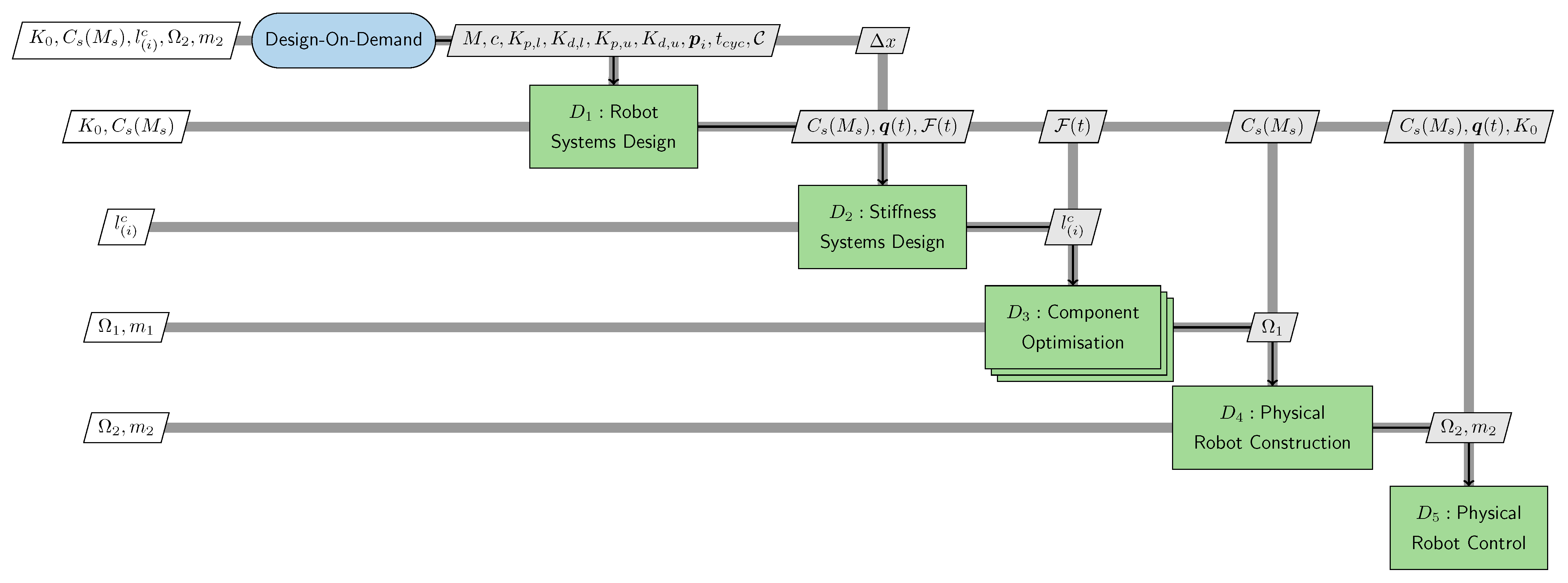
Accommodating constraints arising from cable routing, actuator placement, assembly feasibility, etc., can be dealt with effectively via topology optimisation. Moreover, 3D printing enables realising the resulting complex geometry of the components cost-effectively. Initial attempts at optimising robot structures were limited to a single load case. For example, only the critical load case corresponding to a fully stretched configuration of the robot arm was considered in [42]. Load conditions corresponding to more than one static pose of the robot and different material properties were considered in [43,44,45]. Furthermore, critical load conditions corresponding to a given set of trajectories within the workspace were considered to arrive at globally valid performance measures for resulting structures in [46]. However, identifying trajectories corresponding to critical load cases and their relevance to a specific task of interest is non-trivial for robots. A distributed optimisation paradigm was discussed in [47] to obtain individual structures of a multi-component robot. Furthermore, a distributed optimisation consisting of co-designing component parameters and controllers combined with structural optimisation for designing a humanoid arm was presented in [48]. The benefit of such methods is in decomposing the system-level optimisation problem into sub-problems, allowing for independent design. However, most of these optimisation architectures are not fully decoupled, requiring a coordination strategy to maintain consistency between shared design variables as described in [49]. An approach based on the so-called solution space was presented in [50] as a strategy to decouple a multi-component system, enabling the independent design of the respective components. A meta-model-informed decomposition was introduced in [51,52], eliminating the need for coordination between sub-problems. The current work adopts such a distributed optimisation approach by decomposing the system-level requirements into component-level specifications, presenting a computationally tractable way to compute mass optimal topologies of robotic links.

3. Method Overview

Conventional bottom-up design processes are generally experience driven and are characterised by expensive, time-consuming design iterations. On the other hand, as discussed in [53], top-down design approaches attempt to eliminate cyclic dependencies for the efficient design of multidisciplinary engineering systems with inter-dependant components. In this work, we propose the top-down design of modular robots, adopting the V-model used in automotive and aerospace industries and introduced in [54]. This approach’s essential idea, also discussed in [55,56], is the decomposition of system-level goals as realisable component-level specifications.
The proposed multidisciplinary design process is summarised in an extended design structure matrix (XDSM) [57] and is illustrated in Figure 2. The XDSM provides information regarding both the inputs and the outputs at each stage of the design process and the involved sequence of steps. For example, the design step  D 3 involving topology optimisation of the components is only performed after step  D 2 , which involves computing the stiffness distribution per component from the quantities of interest (QoIs) associated with the end-effector deflection.
The essential ingredient of the approach is an explicit definition of the higher-level requirements of the system. These requirements are fed into the design process in Figure 2 and define the acceptable ranges of the QoIs. For example, to demonstrate the working of the proposed computational systems design process, a robot design satisfying the requirements specified in Table 2 needs to be identified. The requirements correspond to a representative pick and place application where the robot’s end-effector is supposed to move a payload of 1 k g between the specified initial and final positions. The top-down design process aims to identify component-level specifications required to realise such a robot using the so-called bottom-up and top-down mappings.

3.1. Bottom-Up Mapping

The mapping between the lower-level design variables (DVs) to the higher-level QoI variables, which are subject to the system-level requirements (such as in Table 2), is called a bottom-up mapping. Such a mapping allows the evaluation of the QoIs for chosen DV values. In other words, the satisfaction of the requirements by design sampled from the design space can be evaluated using bottom-up mapping. For example, design step  D 1 involves computing the system-level properties such as the time taken to complete the task via multi-body simulation of a robot design sampled from the design space. This allows the classification of the design as satisfying or violating the specified requirements. In  D 2 in Figure 2, the system-level end-effector deflection under the applied load is computed given the individual component-level stiffness values discussed in Section 6.

3.2. Top-Down Mapping
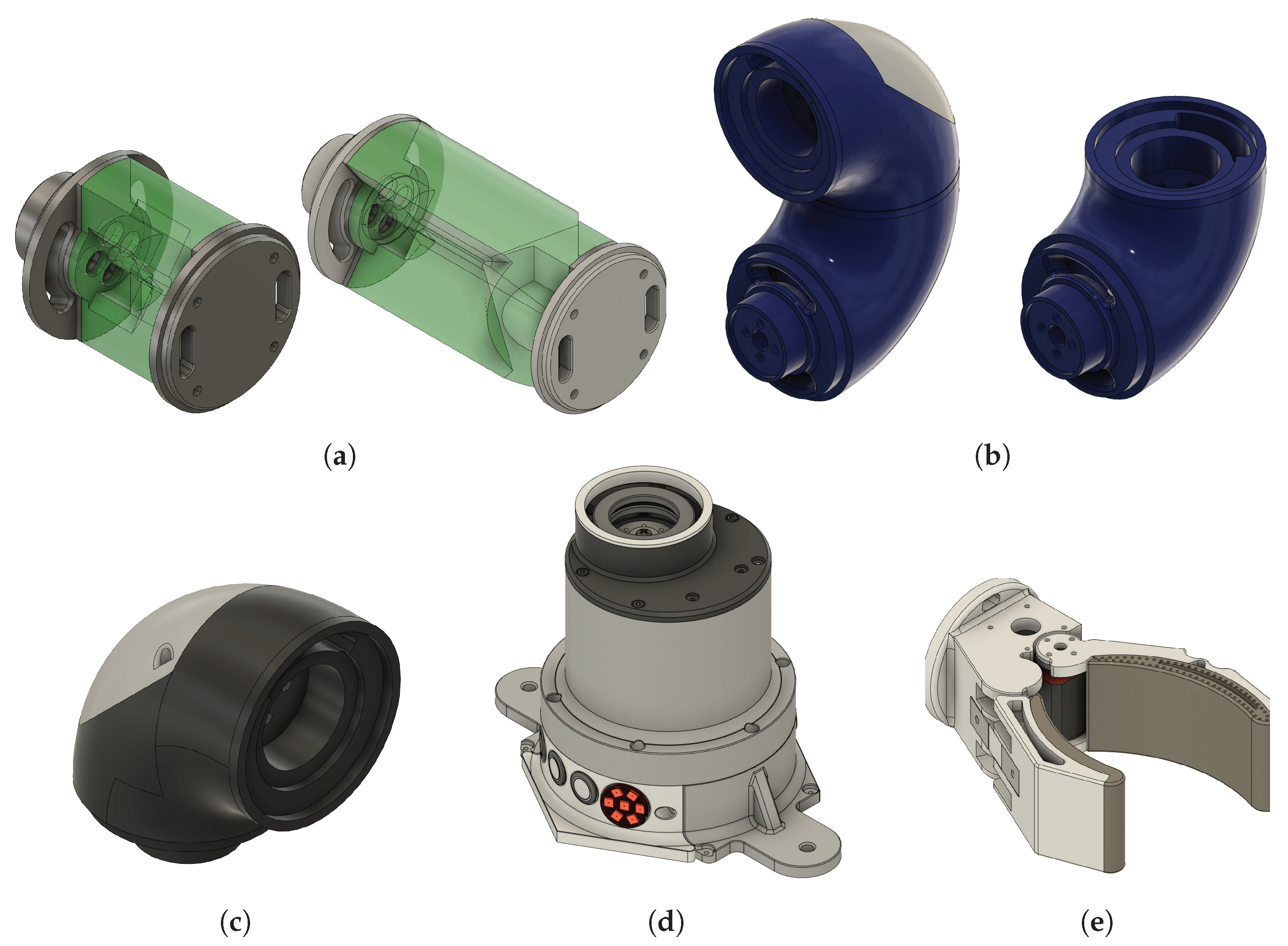
In contrast, top-down mapping refers to the decomposition of system-level requirements presented in the form of QoIs to identify admissible component-level DV values, for example, identifying specific motor parameters to complete a task within the specified cycle time. The first design step  D 1 poses the problem of finding a suitable robot architecture as an informed search problem. In this case, a top-down mapping could correspond to the permissible modules that can be used given the total allowable cost of the robot, as elaborated in Section 5. Similarly, in the stiffness design step  D 2 , the system-level requirement of the end-effector deflection is decomposed as permissible component-level compliance energies used in the structural optimisation problem.

4. Module Design

The designed set of modules M consists of actuation, structural, and end-effector elements that can be assembled to generate fully functional robotic systems as depicted in Figure 3. Generally, the kinematic configurations of such modules are chosen to span a vast design space consisting of classical robot architectures as discussed in [58]. In addition, the module design accounts for compatibility, manufacturability, and assembly constraints to facilitate their physically feasible combination. Furthermore, to realise low-cost, lightweight robots, all the modules are constructed only using lightweight 3D-printed structural elements and low-cost off-the-shelf components.

4.1. Detail Design

The modules are categorised into actuated, passive, and end-effector as shown in Figure 3. The modules’ details and classifications are presented in the current section.

4.1.1. Actuation Modules

Owing to their low cost, torque range, and compact dimensions, servo motors of the SMS series offered by Feetech (https://feetechrc.com/, last accessed on 16 June 2023) were chosen as the drivers of the actuation modules. Furthermore, three specific torque classes of the motors were chosen to design the actuation modules.
Base module: The base module houses the electronics, controller, and base motor within a housing. The highest torque-rated motor from the chosen family of motors, the SM120BL, is included in the base. Moreover, all further modules assembled on the base module are powered via a standard wall power outlet or by a portable battery https://www.makita.de/product/bl1850b.html, last accessed on 16 June 2023) that can be connected to the base module shown in Figure 3d. The base module is always fixed, allowing the other modules to be connected to it to generate serial manipulators.
Joint module: The joint module consists of a housing that holds the motor and provides interfaces for cabling, electronic connectors, and a housing cover. This housing cover, when unscrewed, enables easy troubleshooting of the joint motors. Two classes of joint modules with different maximum torque outputs are constructed using the SM45BL and SM80BL motors.

4.1.2. Passive Modules

To simplify the structural optimisation problem, the passive structural elements are broken into two categories, i.e., optimised structural element (OSE) modules and connectors. OSE modules: In the current study, an OSE module consists of a primitive cylindrical geometry with constraints accounting for assembly, manufacturing, and compatibility. Therefore, the modules comprise a design domain available for topology optimisation and standardised interfaces for connection. For example, as shown in Figure 3a, the volume coloured in green constitutes the design domain  Ω available for structural optimisation, whereas the excluded area provides access to the necessary fastener assembly and cable routing. This involves identifying tools necessary to insert, locate, and fasten the screws and providing free access throughout the tools’ range of motion. Furthermore, the spaces for the cable routing account for the number of cables and the additional slack needed for the unhindered movement of the joint throughout its range.
Connectors: Passive elements that assume non-cylindrical geometry are categorised as connectors and are excluded from the topology optimisation problem. The connectors facilitate the modification of the rotation axis of any two consecutive modules.

4.1.3. End-Effector Modules

An end-effector module, such as the one shown in Figure 3e, allows the constructed robots to interact with the environment and perform the specified task. An end-effector is always the terminal module attached to the kinematic tree, i.e., at the end of the robot’s arm, as shown in Figure 1c.

4.2. Interface Design

To enable modularity, the design of both the mechanical and electrical interfaces between the modules must be addressed. The interface design allowing a flexible combination of modules is presented in the current section.

4.2.1. Mechanical Interfaces

The modules can be connected via standardised interfaces designed to reduce complexity and simplify the assembly process, and are illustrated in Figure 3. The interfaces (1) enable the effective decoupling of the OSEs from components that are not involved in the structural optimisation, (2)  allow the connection of the OSEs with the connector and joint modules, making them physically realisable, and (3) accommodate physical attributes for cable routing and component assembly. As shown in Figure 3a, an OSE shown in green is sandwiched between the interfaces shaded in grey, forming the OSE modules.
Several practical design choices have also been made to simplify the assembly process. All the modules use standard M3 screws for assembly, and the chosen fastener orientation, size, and torque strength ensure secure and reliable connections. Not only does this inform the design domain of the OSE, but it also determines the print orientation of the respective OSEs such that the embedded nuts can handle the loads upon fastening. Furthermore, the design enables the assembly of a joint module to an OSE within 10 min and the complete assembly of a five-degrees-of-freedom robot within 2 h . This enables quick troubleshooting and lowers the downtime of the robot.

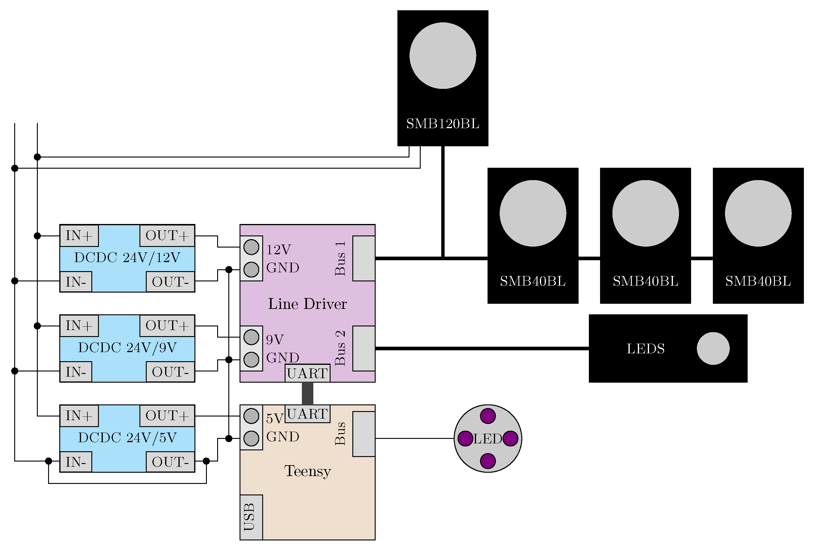
4.2.2. Electrical Interfaces

A serial communication layer is chosen, which enables realising a relatively simple electronic architecture while accommodating several actuated modules. All the joint modules are independently connected to the microcontroller via a serial communication interface with a unique bus index. This unique index associated with each actuated module is automatically inferred post-assembly. The motors used are actuated in velocity control mode, where the user can set the reference position and velocity. The overall electronics layout for the physically realised robot resulting from the design step  D 4 (in Figure 2) is presented in Figure 4. Within the scope of the current work, the robot is limited to simple robot control tasks such as tracking a predefined trajectory, leading to the choice of a low-cost microcontroller. However, one may need more capable control hardware when dealing with computationally intensive sensors (such as images or point cloud inputs) or scenarios involving expensive decision-making steps (online planning or MPC). While off-the-shelf systems are accessible and cheap for prototyping, as the number of modules increases, custom PCBs could potentially be economically viable. They provide more flexibility in design and enable easy replacement of electronic components in cases of shortage.

5. D 1 :  Robot System Design

As illustrated in Figure 2, the design step  D 1 accepts the requirements defined in Table 2 along with the available modules M and assembles them to identify a feasible robot architecture. The systems design of the robot involves two main steps: (1)  the identification of a feasible robot architecture and (2) the synthesis of a suitable controller. The first step involves traversing the design space to search for a suitable set of modules capable of reaching the required positions. The second step involves identifying a suitable controller to track the given path while satisfying the performance requirements.

5.1. Connection Rules c and Compositions  C ( M )

While connecting the modules to generate robots, not all combinations yield useful outputs. As discussed in [28], connection rules ground the algorithm to identify physically feasible configurations and to guide the design process with the semantic information of the modules. For example, connecting the outputs of two joint modules to each other would effectively not produce any useful output torque. To capture only meaningful module combinations, a specific set of connection rules are defined that govern the interaction between the modules. This enables the generated robot assemblies, called compositions, to be meaningful and physically realisable. The phrases composition, robot composition, and architecture can be used interchangeably in the current context. The set of all the connection rules is denoted by  c = { c 1 , c 2 , , c n } , where c i is the ith connection rule. A more comprehensive discussion on computational abstractions for the design of modular robots can be found in [29].
Among all the available modules M, any number can be selected ( M s M ) and assembled to generate robot compositions,  C ( M s ) . Additionally, for a composition to be meaningful, the assembly of modules must adhere to the prescribed connection rules c. Therefore, a physically feasible composition  C p ( M s , c ) admits a given set of modules and their associated connection rules. Restricting the designs to C p guarantees the physical feasibility of the compositions resulting from step  D 1 .

5.2. Automatic Design of Modular Robot Manipulators

As described in Section 3, identifying a feasible composition is posed as an informed search problem. Additionally, an inverse dynamics controller parameterised in terms of its controller gains K p and K d is employed to simplify the controller synthesis. Every composition sampled from the design space is evaluated using the Drake simulation toolbox with respect to the defined task, following which the controller gains K p and K d are tuned to satisfy the cycle time requirement.
Alternatively, one could also pose the synthesis of the controller as an optimal control problem to minimise auxiliary QoIs such as energy expended, as done in [59]. Furthermore, as discussed in [58], a holistic approach could be taken for identifying architecture and controllers together. Another method could involve posing the entire problem as a mixed integer non-linear programming problem with the choice of the discrete modules and continuous control parameters as design variables as suggested in [60], along with a path planning strategy presented in [61].

5.3. Problem Formulation

Owing to the effective identification of modular robot architectures by posing them as informed search problems, as described earlier in Section 2, we employ the  A * algorithm presented in [62] to explore the design space of the robot compositions. During the traversal of the kinematic tree, each intermediate composition is iteratively expanded until the kinematic requirements are met, i.e., until the robot’s end-effector reaches the prescribed configurations. Each expanded composition is enforced to conform to the connection rules described in Section 5.1. For a quantitative distinction between the modules, they are associated with a cost based on their relative complexity. For example, the joint modules housing the actuators would have higher associated costs than the 3D-printed connectors or the OSEs. Therefore, for the search problem, the path cost  g p a t h ( · ) is the same as the cost associated with the modules. Additionally, the distance between the realisable position of the end-effector of the composition and the prescribed position is used as a heuristic  h ( · ) to guide the search process. The heuristic cost is evaluated by solving an inverse kinematics (IK) problem. As described in [10], such a heuristic does not overestimate the cost to reach the goal and is hence admissible. Therefore, the design step  D 1 can be mathematically formulated as,
min C ( M ) , K c I , G ( g p a t h ( C ( M ) ) + h ( C ( M ) ) ) ,
subject to , p e e f ( 0 ) = p I , p ˙ e e f = 0 ,
g ( q ( t ) , q ˙ ( t ) ) 0 ,
g g o a l ( q ( T ) , q ˙ ( T ) , p G ) 0 ,
C ( M ) C p ( M , c ) ,
where q ( · ) Q is the configuration of the robot. Limits on joint angles, velocities, torques, and the permissible ranges of the QoIs are enforced as inequality constraints  g ( · )  (1c). Additionally, inequality constraints restricting the minimum distance between any two bodies accounting for potential self and environmental collisions are also implemented in (1c). The sum of the path cost,  g p a t h ( · ) , and the heuristic cost,  h ( · ) , corresponds to the cost function  f ( · ) for the optimisation problem as explained in [62]. The cost function is evaluated at both the initial and final end-effector positions  p I , p G , whereas the constraint on the total completion time is used to tune the control DVs, K p and K d . The required end-effector positions and velocities,  p e e f , p ˙ e e f R 3 , at times  t = 0 and  t = T are enforced as boundary constraints (1b,1d). Finally, the constraint (1e) guarantees the physical feasibility of the compositions by connecting the modules according to their admissible connection rules. To demonstrate the automatic design process involved in systems design step  D 1 , an example involving the identification of a composition moving between two locations in the presence of collisions is illustrated in Figure 5. Primitive geometric elements in light grey were placed within the robot environment as obstacles. Furthermore, the robot must move between two prescribed locations depicted as brown spheres. In such a scenario, an admissible module satisfies the compatibility rules and the collision constraints are enforced as a minimum distance threshold constraint between two bodies. However, it is important to note that the formulation in Problem (1a) does not guarantee a solution for the stated requirements.
Alternatively, by setting the cost function  f = 0 , the problem can be converted to one of feasibility, leading to a constraint satisfaction problem [62,63]. Instead of one solution, a set of solutions that satisfy the given requirements could be identified by constructing the so-called solution spaces as demonstrated in [50,55]. However, it is not directly applicable in the current case involving a mixed set of continuous and discrete DVs. The current approach can be easily extended to identify a family of feasible compositions by not terminating the search but continuing it until all the compositions satisfying the requirements are identified.

6. D 2 , D 3 : Lightweight Structure Design

The outputs of the computational design step  D 1 solving Problem (1a) described in Section 5 are a composition and a corresponding controller (Figure 2). The design step  D 2 involves optimising selected passive structural elements of the robot or the OSEs as described in Section 4. Unlike in [42] or [45], we consider multiple load cases, each corresponding to a quasi-static snapshot of the robot during its motion, accounting for the dynamic loads. Therefore, unlike the works described in Section 2, the current work accounts for dynamic load cases corresponding to the robot’s motion between the given pick and place locations.

6.1. Structural Optimisation Setup

Structural optimisation of modular robots is generally challenging as it (a) involves elements with complex geometries, (b) requires handling complex and case-dependent boundary conditions, (c) contains multiple interdependent components that need to be optimised together, and (d) needs to account for multiple load conditions. As discussed briefly in Section 4, problem (a) is avoided by decoupling the structural components to be optimised, called the OSEs, from the components with fixed geometries that are not optimised. A primitive cylindrical design domain is chosen for the OSEs, as illustrated in Figure 3a. Furthermore, as also discussed in Section 4, the OSEs are connected to the other modules via fixed interfaces, standardising the boundary conditions for all the OSEs, addressing (b). Finally, based on the requirement of the end-effector deflection  Δ x c stated in Table 2, the system-level critical compliance energy  l c of the robot is decomposed to allowable component-level compliance specification corresponding to each of the OSEs  l ( i ) c . This decomposition allows the optimisation of the components independent of each other, thus parallelising the process and significantly reducing the computational time, alleviating problem (c). The system-level critical compliance and its distribution corresponding to the length of the OSE follows from Equation (3).
l c = m p g Δ x c ,
l ( i ) c = l c s ( i ) i s ( i ) ,
where s is the length of the ith OSE, m p is the mass of the payload (1 kg), and g = 9.81 m s 2 is the acceleration due to gravity. The decomposition depicted in Equation (3) enables breaking down the system-level requirements to the component level without compromising the system-level performance. Additionally, such a decomposition allows the independent optimisation of individual OSEs, essentially parallelising the optimisation sub-problems.
For the obtained composition and controller from  D 1 , the wrenches experienced at each interface (constituting the forces and moments) during the robot’s motion between time t = 0 and T are extracted as  F ( t ) R 6 via simulation. One such interface wrench  F 1 corresponding to the base of the first OSE is illustrated in Figure 6. Critical load cases corresponding to each dimension  j = 1 6 of the ith interface wrench are extracted as  F ( i ) , j c , which corresponds to their respective absolute maximum values, as defined in Equation (5). Each OSE would be subjected to six load cases, each corresponding to the absolute maximum values of the respective degree-of-freedom.
F ( i ) , j c = F ( i ) ( t ( i ) , j c ) , where j = 1 6 ,
t ( i ) , j c = argmax t F ( i ) , j ( t ) ,
where F ( i ) , j c is a vector of size 6 containing the jth critical load case for the ith component. For the structural optimisation of the ith OSE, the objective is to minimise its mass while not exceeding the component-level critical compliance computed from Equation (3) for all j critical load cases.

6.2. Problem Formulation

Following Equations (3) and (5), each sub-problem is a topology optimisation problem corresponding to an OSE. It is to be noted that, following the proposed procedure, the problem of monolithic optimisation of a multi-component robotic system in the presence of dynamic load cases is decomposed into smaller sub-problems dealing only with the static structural optimisation of OSEs, thus significantly reducing the complexity of the problem. The topology optimisation sub-problem is mathematically formulated as,
min ρ e ( x ) m ( i ) ( ρ e ( x ) ) , such that l ( i ) l ( i ) c , for load cases F ( i ) , j c , and j = 1 6 ,
where  m ( i ) , l ( i ) are the mass and compliance energy of the ith OSE, respectively, and  ρ e represents the elemental density field over the available design domain  Ω of the ith OSE. Following the procedure would result in four independent topology optimisation sub-problems formulated according to Equation (6). Each topology optimisation sub-problem optimises the elemental density field  ρ e over the design domain shown in Figure 3. Moreover, each sub-problem is subjected to unique critical compliances  l ( i ) c and loads, derived according to Equations (3) and (5), resulting in unique topologies for each of the OSEs, as seen in Figure 7.

7. Results and Discussion

Following the steps described in Figure 2, a robot with a feasible architecture, controller, and structural stiffness that satisfies the specified requirements Table 2 was obtained along with the optimised OSE modules, as depicted in Figure 1b. While exploring feasible designs via an informed search in  D 1 , the capability of the intermediate compositions to reach the given initial and final positions was then evaluated using the IK and the inverse dynamics controller within the Drake simulation toolbox [64]. The constructed robot is controlled in the velocity control mode, where the user can manipulate both the position and control of each robot joint. The trajectory resulting from the simulation is extracted and tracked in hardware via a custom controller. The controller used in the current work to actuate the hardware prototype is also made available in the data availability statement present in Section 8.
It should be noted that the total number of degrees of freedom of the identified task-specific robot is four and hence is cheaper for the number of actuators used as opposed to similar generally deployed standard robots (for example, the commercially available MyCobot Pro 600 from Elephant robotics) with six or seven degrees of freedom. This is attributed to the designed robot specialising only in solving the required task. However, such a comparison should be performed, noting that the latter is a general-purpose robot, while the former is tailor-made robot for only a specific task. While the total number of required degrees of freedom depends significantly on the task description, chosen modules, and obstacles present in the workspace, the reconfigurability of the modules allows for realising tailor-made robots for any new scenarios. In addition, as demonstrated, the systems design procedure can potentially identify compositions with fewer actuators and non-intuitive kinematics for a specified task.
The interface wrenches  F recorded during the robot’s motion are input to the design step  D 2 . One such interface wrench corresponding to the base of the first OSE,  F ( 1 ) , is presented in Figure 6. Critical loads corresponding to first OSE  F ( 1 ) , j c , extracted according to Equation (5), are marked with the diamond shape (⧫) in Figure 6.
Table 3 presents the component-level critical compliance energies decomposed from the system-level critical compliance energy following Equation (3). Following this, the optimisation problem formulated in Problem (6) is solved using a commercially available topology optimisation software, Altair Optistruct 2019.1.1, and the resulting topologies of all the OSEs are illustrated in Figure 7a. Additionally, the obtained OSEs are post-processed in Meshmixer 3.5 and Autodesk Fusion 360 2.0. As a final step, the OSEs are smoothed and combined with the interface flanges to form the complete modules, illustrated in Figure 7b. The masses of the resulting 3D-printed OSE modules ( m p r i n t , r i g i d ) are tabulated in Table 4.
Figure 7. (a) Results of the topology optimisation of the OSEs. (b) Post-processed OSEs fused with the interfaces, i.e., the resulting design of the modules that can be additively manufactured.
Robotics 12 00091 g007
The simulated motion of the robot with the post-processed modules between the specified positions, along with the corresponding joint torques realised, is illustrated in Figure 8.

7.1. Comparison of Modules with Design Domain as Aluminium Tubes

Alternatively, hollow, thin metallic cylindrical tubes made of aluminium are often used as structural elements of robots, for example, in the case of Universal Robots. To demonstrate the benefit of the proposed systems design procedure, we compare the resulting robot with one that is designed using only cylindrical tubes. In such a design, a module consists of a cylindrical tube and interfaces made from aluminium 6061. For comparison, we repeat the decomposition of the system-level critical compliance to the component level for the tube modules. In contrast to the topology optimisation problem, the optimal tube thickness that satisfies the prescribed requirements is computed by performing a parametric optimisation. The resulting thicknesses  t ( i ) per module are tabulated in Table 4. However, considering the physical feasibility of realising such components, the smallest commercially available thickness  t ( i ) p of  0.5  mm is chosen. Finally, the masses of the realisable modules ( m t u b e s , a l u ) are presented in Table 4.
The total mass of the manufactured topology-optimised modules is 0.42  kg compared to the 0.49  kg of the aluminium modules. The comparison of masses in Table 4 illustrates a  16 % lower mass of the structural components between the two designs. The reduction in mass also translates to reduced peak torques, associated with the resulting composition while in motion. Moreover, the latter does not account for the design space constraints such as wiring and fastener assembly as explained in Section 4, which could potentially result in further heavier components when incorporated. However, it should be noted that the choice of components depends on the specific choice of loads and the scale of the robot. For example, aluminium tubes are accessible to the source and manufacturer and provide enough stiffness for most common load cases. On the other hand, any decrease in the mass of components of tetherless robots such as humanoids, drones, or quadrupeds can be associated with a benefit corresponding to a longer operation time. In general, the difference in the benefits may not be significant for smaller-scale fixed-base robots as they are industrial scale robots [65]. However, a detailed study on such components’ scalability and the associated costs must be conducted to understand their applicability to other scenarios.

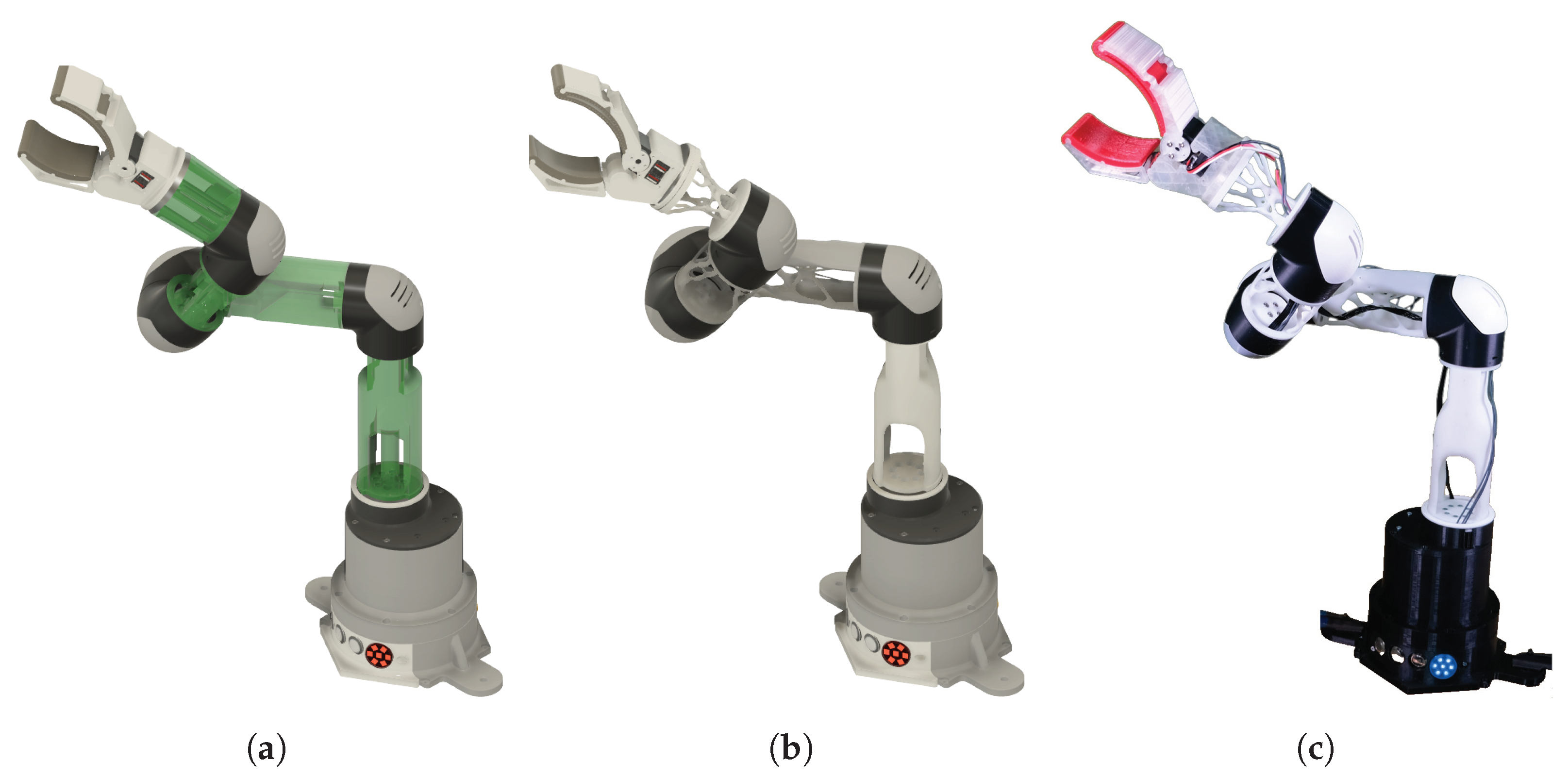
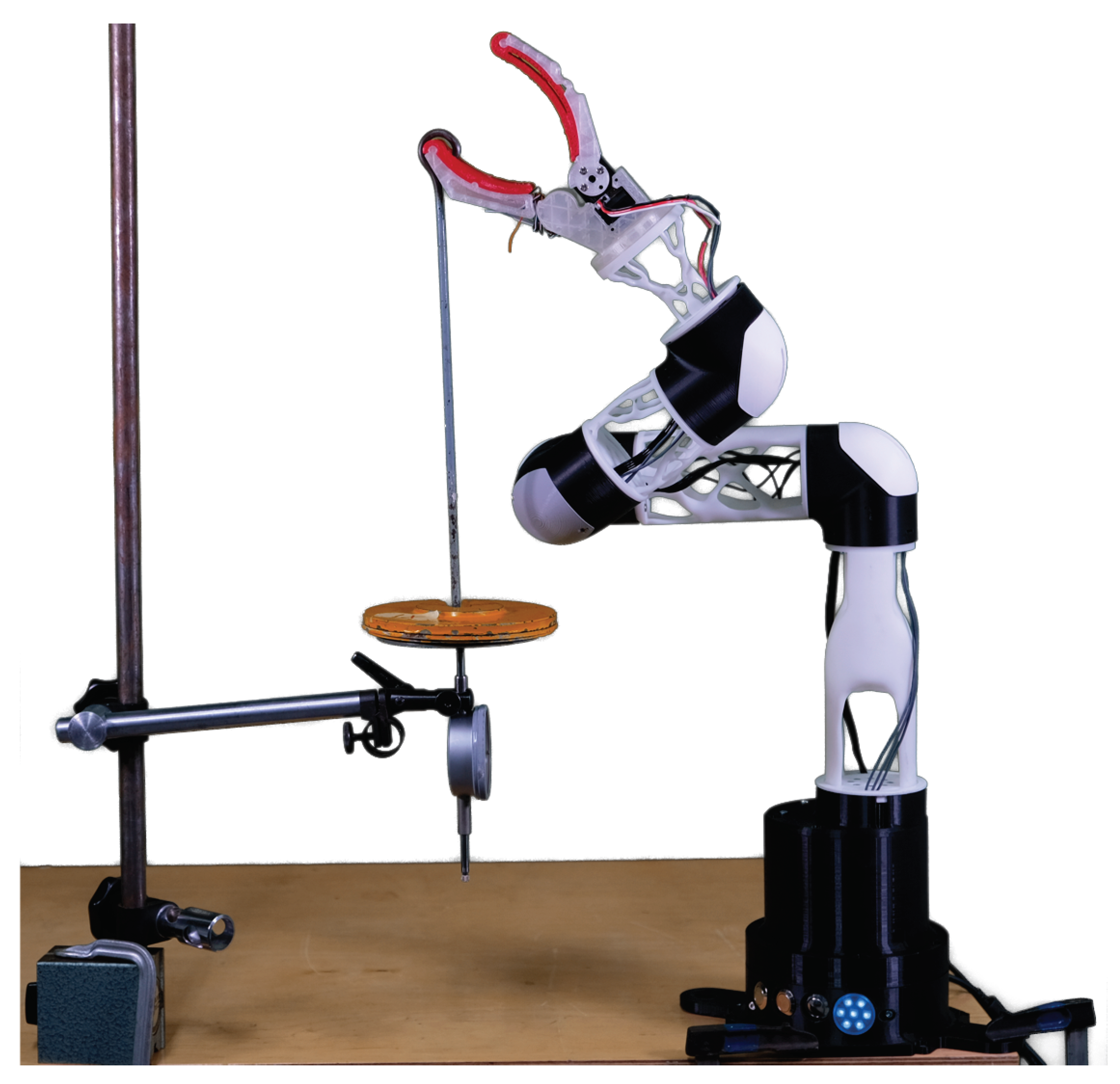
7.2. Construction and Testing of the Physical Prototype

For the construction of the physical prototype, the OSEs were 3D printed using the Rigid 10K (the Rigid 10k material from Formlabs) resin developed by Formlabs (https://formlabs.com/, last accessed on 16 June 2023). A prototype of the manufactured post-processed modules is shown in Figure 1c. Finally, the constructed robot was evaluated with respect to the requirements in Table 2. The recorded motion time for the physical robot between the specified locations is observed to be  4.5  s, close to the prescribed limit value. Moreover, the end-effector deflection of the robot under 1 kg loading is tested. The robot’s initial pose is chosen for testing since the load conditions (Figure 6) are for the specified motion starting from this pose. The setup to test the end-effector deflection is presented in Figure 9. The measured deflection of the end-effector is around 11 mm, deviating from the specified requirements. Although the observed structural deflection of the OSEs is relatively small and potentially within the derived component-level compliance energy, it is essential to note that a considerable portion of the end-effector deflection can be attributed to the unaccounted structural stiffness of the joints. Therefore, several potential modifications could be made to the joint and end-effector modules to improve the overall system stiffness. For example, the joints could be redesigned using alternative materials to reduce compliance. Furthermore, the stiffness of the end-effector module itself could be modified. By exploring these modifications, it may be possible to reduce the observed system-level deflection further.
As described earlier, the robot consists of OSE modules made of rigid resin, while the joint modules were printed in ABS. This ensures that the joint modules can handle the necessary operational loads while not being expensive to manufacture. It is observed that the ABS components undergo deformation, particularly under prolonged stress or elevated temperatures. However, these deformations do not significantly affect the performance of the robot. On the other hand, continuous exposure to sun or water may substantially deteriorate the strength and stiffness of the components, even within a few months. Despite loading the end-effector, the 3D-printed parts did not fail during the static loading experiments. However, it is observed that any misalignment between the modules while mounting and the backlash of the modules are two additional contributors to deflection.

7.3. Cost and Scalability of the Modules

A detailed analysis of various costs involved in the production of the prototype is presented in this section. The details shown in Table 5 provide an overview of the cost breakdown of the entire robot prototype. The constructed robot prototype is estimated to cost around EUR 2862.6, significantly cheaper than the robots from the industrial or collaborative classes. On the other hand, a commercial robot of the same class from Elephant Robotics  (https://shop.elephantrobotics.com/en-ie/collections/mycobot/products/mycobot-pro-raspberry-pi, last accessed on 16 June 2023) costs around EUR 2369.95. It should be noted that the current costing concerns low volume prototyping, and a comprehensive study on the effect of scaling on the total cost of production needs to be conducted.

8. Conclusions and Future Work

The current work proposes a multidisciplinary computational design strategy to realise low-cost and lightweight modular serial manipulators. A set of custom-designed modules accounting for manufacturability and assembly is presented. The design choices associated with material selection, manufacturing, and scale of production, i.e., the context for using aluminium tubes vs. 3D-printed elements, are briefly discussed. An attractive future direction could be using 3D-printed components and aluminium tubes to realise a feasible composition.
A search-based exploration strategy is employed to find a feasible robot architecture. However, since the modules are pre-defined, any physically feasible compositions may not satisfy the given requirements. The requirements must be modified or new modules must be introduced. Moreover, the choice of heuristics can be improved to include module-specific information. Alternatively, the heuristic can encode system-level information to guide towards a non-intuitive design. Future work would extend the current heuristic function, exploring the usage of the eigenvalue of the resulting mass matrix at each iteration as an indicator of peak torques needed, as discussed in [66].
A procedure to decompose system-level structural requirements to component-level specifications accounting for dynamic loads, leading to independent topology optimisation sub-problems, is introduced. The structural optimisation of the OSEs is performed via mass minimisation while constraining their critical compliance energy. The resulting components are realised via additive manufacturing and assembled to generate a physical prototype. However, the shortcoming of the design process shown in Figure 2 is that the mass and inertial properties of the components are not known in step  D 1 and are only computed later in  D 2 . Therefore, future work would extend the procedure to a fully automatic optimisation process that includes an informed decomposition by training meta-models for design domains, as introduced in [52]. Another potential direction is to perform mass minimisation with the minimum eigenfrequency requirement as a constraint, accounting for the dynamic stiffness of each of the OSEs, as explored in [67].
In conclusion, while the proposed top-down design procedure has shown promising results for the design of modular robots, several avenues of research may be explored. Firstly, the applicability of the proposed method with a different set of modules [6,7] than the ones proposed may be investigated. Additionally, the application of the proposed method to an industrial scale robot and an exhaustive comparison and benchmarking according to [68] could be explored. This could shed light on the module design and its effect on the resulting robot architectures to help develop a general design guideline for realising modular robots.   

Supplementary Materials

The following supporting information can be downloaded at: https://www.mdpi.com/article/10.3390/robotics12040091/s1.

Author Contributions

Conceptualization, A.S., A.V.S., M.A. and M.Z.; data curation, A.S.; formal analysis, A.S.; funding acquisition, A.V.S. and M.Z.; investigation, A.S., A.V.S., J.F. and M.Z.; methodology, A.S., J.F. and M.Z.; project administration, A.V.S. and M.Z.; resources, A.S., A.V.S. and M.A.; software, A.S., A.V.S., J.F. and M.A.; supervision, M.Z.; validation, A.S., A.V.S. and J.F.; visualisation, A.S. and J.F.; writing—original draft, A.S. and J.F.; writing—review and editing, A.S., A.V.S. and M.Z. All authors have read and agreed to the published version of the manuscript.

Funding

Thecurrent work was funded by the Bavarian Ministry of Economic Affairs, Regional Development and Energy as part of the Bavarian Collaborative Funding Programme (BayVFP)-Funding Line Digitalisation-Funding Area Electronic Systems. The funding was provided the under the project name “LCL Robots—Lowcost Lightweight Robots on Demand”, with the project allocation number 07 02/683 57/98/20 252/22 253/23 254/24.

Institutional Review Board Statement

Not applicable.

Informed Consent Statement

Not applicable.

Data Availability Statement

The data presented for the systems design of modular robots have been made public and can be reproduced following the instructions given in the associated GitHub repository: https://github.com/akhilsathuluri/automatic-design-on-demand, last accessed on 16 June 2023. The data for reproducing the control of the hardware prototype can be accessed via the GitHub repository: https://github.com/akhilsathuluri/lcl-robot-control, last accessed on 16 June 2023. Further data regarding the topology optimisation and its implementation shall be made available upon request.

Acknowledgments

The authors would like to thank Michael Schweiger, Fernando van der Vinne, and Leander Merbecks for their assistance in constructing the prototype, Katja Zajicek for administrative co-ordination, and Lukas Krischer for helpful discussions on the topic. The authors would especially like to thank Markus Mörtl and Sebastian Perez Ramirez for their contribution to the cost analysis.

Conflicts of Interest

The authors declare no conflict of interest.

Abbreviations

The following abbreviations are used in this manuscript:
OSEOptimised structural element
DVDesign variable
QoIQuantity of Interest
XDSMExtended design structure matrix

References

  1. ISO 12018:2011; Robots and Robotic Devices—Safety Requirements for Industrial Robots—Part 1: Robots. Standard, International Organization for Standardization: Geneva, Switzerland, 2011.
  2. ISO 15066:2016; Robots and Robotic Devices—Collaborative Robots. Standard, International Organization for Standardization: Geneva, Switzerland, 2016.
  3. Aaltonen, I.; Salmi, T. Experiences and expectations of collaborative robots in industry and academia: Barriers and development needs. Procedia Manuf. 2019, 38, 1151–1158. [Google Scholar] [CrossRef]
  4. Rosenstrauch, M.J.; Krüger, J. Safe human–robot-collaboration-introduction and experiment using ISO/TS 15066. In Proceedings of the 2017 3rd International Conference on Control, Automation and Robotics (ICCAR), Nagoya, Japan, 24–26 April 2017; IEEE: Piscataway, NJ, USA, 2017; pp. 740–744. [Google Scholar]
  5. Seo, J.; Paik, J.; Yim, M. Modular reconfigurable robotics. Annu. Rev. Control Robot. Auton. Syst. 2019, 2, 63–88. [Google Scholar] [CrossRef]
  6. Romiti, E.; Malzahn, J.; Kashiri, N.; Iacobelli, F.; Ruzzon, M.; Laurenzi, A.; Hoffman, E.M.; Muratore, L.; Margan, A.; Baccelliere, L.; et al. Toward a Plug-and-Work Reconfigurable Cobot. IEEE/ASME Trans. Mechatron. 2021, 27, 3219–3231. [Google Scholar] [CrossRef]
  7. Althoff, M.; Giusti, A.; Liu, S.B.; Pereira, A. Effortless creation of safe robots from modules through self-programming and self-verification. Sci. Robot. 2019, 4, eaaw1924. [Google Scholar] [CrossRef] [PubMed]
  8. Martins, J.R.R.A.; Ning, A. Engineering Design Optimization; Cambridge University Press: Cambridge, UK, 2022. [Google Scholar]
  9. Katz, B.; Di Carlo, J.; Kim, S. Mini cheetah: A platform for pushing the limits of dynamic quadruped control. In Proceedings of the 2019 International Conference on Robotics and Automation (ICRA), Montreal, QC, Canada, 20–24 May 2019; IEEE: Piscataway, NJ, USA; pp. 6295–6301. [Google Scholar]
  10. Ha, S.; Coros, S.; Alspach, A.; Bern, J.M.; Kim, J.; Yamane, K. Computational design of robotic devices from high-level motion specifications. IEEE Trans. Robot. 2018, 34, 1240–1251. [Google Scholar] [CrossRef]
  11. Toussaint, M.; Ha, J.S.; Oguz, O.S. Co-Optimizing Robot, Environment, and Tool Design via Joint Manipulation Planning. In Proceedings of the 2021 IEEE International Conference on Robotics and Automation (ICRA), Xi’an, China, 30 May–5 June 2021; pp. 6600–6606. [Google Scholar] [CrossRef]
  12. Lipson, H.; Pollack, J.B. Automatic design and manufacture of robotic lifeforms. Nature 2000, 406, 974–978. [Google Scholar] [CrossRef] [PubMed]
  13. Kelmar, L.; Khosla, P.K. Automatic generation of kinematics for a reconfigurable modular manipulator system. In Proceedings of the 1988 IEEE International Conference on Robotics and Automation, Philadelphia, PA, USA, 24–29 April 1988; IEEE: Piscataway, NJ, USA, 1988; pp. 663–668. [Google Scholar]
  14. Sims, K. Evolving virtual creatures. In Proceedings of the 21st Annual Conference on Computer Graphics and Interactive Techniques, Orlando, FL, USA, 24–29 July 1994; pp. 15–22. [Google Scholar]
  15. Chen, I.M. On optimal configuration of modular reconfigurable robots. In Proceedings of the 4th International Conference on Control, Automation, Robotics, and Vision, Singapore, 4–6 December 1996. [Google Scholar]
  16. Paredis, C.J.; Khosla, P. Synthesis methodology for task based reconfiguration of modular manipulator systems. In Proceedings of the 6th International Symposium on Robotics Research (ISRR’93), Hidden Valley, PA, USA, 2–5 October 1993. [Google Scholar]
  17. Zhang, H.; Wang, W.; Deng, Z.; Zong, G.; Zhang, J. A novel reconfigurable robot for urban search and rescue. Int. J. Adv. Robot. Syst. 2006, 3, 48. [Google Scholar] [CrossRef]
  18. Liu, C.; Whitzer, M.; Yim, M. A distributed reconfiguration planning algorithm for modular robots. IEEE Robot. Autom. Lett. 2019, 4, 4231–4238. [Google Scholar] [CrossRef]
  19. Hale, M.F.; Angus, M.; Buchanan, E.; Li, W.; Woolley, R.; Le Goff, L.K.; De Carlo, M.; Timmis, J.; Winfield, A.F.; Hart, E.; et al. Hardware design for autonomous robot evolution. In Proceedings of the 2020 IEEE Symposium Series on Computational Intelligence (SSCI), Canberra, Australia, 1–4 December 2020; IEEE: Piscataway, NJ, USA, 2020; pp. 2140–2147. [Google Scholar]
  20. Moreno, R.; Faiña, A. EMERGE modular robot: A tool for fast deployment of evolved robots. Front. Robot. 2021, 8, 699814. [Google Scholar] [CrossRef]
  21. Zhu, T.; Fernandez, G.I.; Togashi, C.; Liu, Y.; Hong, D. Feasibility study of limms, a multi-agent modular robotic delivery system with various locomotion and manipulation modes. In Proceedings of the 2022 19th International Conference on Ubiquitous Robots (UR), Jeju, Republic of Korea, 4–6 July 2022; IEEE: Piscataway, NJ, USA, 2022; pp. 30–37. [Google Scholar]
  22. Xu, J.; Chen, T.; Zlokapa, L.; Foshey, M.; Matusik, W.; Sueda, S.; Agrawal, P. An End-to-End Differentiable Framework for Contact-Aware Robot Design. In Proceedings of the Robotics: Science and Systems, Virtual, 12–16 July 2021. [Google Scholar] [CrossRef]
  23. Moreno, R.; Liu, C.; Faina, A.; Hernandez, H.; Gomez, J. The EMeRGE modular robot, an open platform for quick testing of evolved robot morphologies. In Proceedings of the Genetic and Evolutionary Computation Conference Companion, Berlin Germany, 15–19 July 2017; pp. 71–72. [Google Scholar] [CrossRef]
  24. Sathuluri, A.; Sureshbabu, A.V.; Zimmermann, M. Robust co-design of robots via cascaded optimisation. In Proceedings of the 2023 IEEE International Conference on Robotics and Automation, London, UK, 29 May–2 June 2023; IEEE: Piscataway, NJ, USA, 2023; pp. 11280–11286. [Google Scholar] [CrossRef]
  25. Fadini, G.; Flayols, T.; Del Prete, A.; Mansard, N.; Souères, P. Computational design of energy-efficient legged robots: Optimizing for size and actuators. In Proceedings of the 2021 IEEE International Conference on Robotics and Automation (ICRA), Xi’an, China, 30 May–5 June 2021; pp. 9898–9904. [Google Scholar] [CrossRef]
  26. Icer, E.; Hassan, H.A.; El-Ayat, K.; Althoff, M. Evolutionary cost-optimal composition synthesis of modular robots considering a given task. In Proceedings of the 2017 IEEE/RSJ International Conference on Intelligent Robots and Systems (IROS), Vancouver, BC, Canada, 24–28 September 2017; pp. 3562–3568. [Google Scholar] [CrossRef]
  27. Whitman, J.; Choset, H. Task-Specific Manipulator Design and Trajectory Synthesis. IEEE Robot. Autom. Lett. 2019, 4, 301–308. [Google Scholar] [CrossRef]
  28. Zhao, A.; Xu, J.; Konaković-Luković, M.; Hughes, J.; Spielberg, A.; Rus, D.; Matusik, W. RoboGrammar: Graph Grammar for Terrain-Optimized Robot Design. ACM Trans. Graph. 2020, 39, 1–16. [Google Scholar] [CrossRef]
  29. Desai, R.; Yuan, Y.; Coros, S. Computational abstractions for interactive design of robotic devices. In Proceedings of the 2017 IEEE International Conference on Robotics and Automation (ICRA), Singapore, 29 May–3 June 2017; pp. 1196–1203. [Google Scholar] [CrossRef]
  30. Desai, R.; Safonova, M.; Muelling, K.; Coros, S. Automatic Design of Task-specific Robotic Arms. arXiv 2018, arXiv:1806.07419. [Google Scholar]
  31. Whitman, J.; Bhirangi, R.; Travers, M.; Choset, H. Modular Robot Design Synthesis with Deep Reinforcement Learning. Proc. AAAI Conf. Artif. Intell. 2020, 34, 10418–10425. [Google Scholar] [CrossRef]
  32. Xu, J.; Spielberg, A.; Zhao, A.; Rus, D.; Matusik, W. Multi-objective graph heuristic search for terrestrial robot design. In Proceedings of the 2021 IEEE International Conference on Robotics and Automation (ICRA), Xi’an, China, 30 May–June 2021; IEEE: Piscataway, NJ, USA, 2021; pp. 9863–9869. [Google Scholar]
  33. Meister, E.; Nosov, E.; Levi, P. Automatic onboard and online modelling of modular and self-reconfigurable robots. In Proceedings of the 2013 6th IEEE Conference on Robotics, Automation and Mechatronics (RAM), Manila, Philippines, 12–15 November 2013; IEEE: Piscataway, NJ, USA, 2013; pp. 91–96. [Google Scholar]
  34. Zardini, E.; Zappetti, D.; Zambrano, D.; Iacca, G.; Floreano, D. Seeking quality diversity in evolutionary co-design of morphology and control of soft tensegrity modular robots. In Proceedings of the Genetic and Evolutionary Computation Conference, Lille, France, 10–14 July 2021; pp. 189–197. [Google Scholar] [CrossRef]
  35. Pigozzi, F.; Tang, Y.; Medvet, E.; Ha, D. Evolving Modular Soft Robots without Explicit Inter-Module Communication using Local Self-Attention. In Proceedings of the Genetic and Evolutionary Computation Conference, Boston, MA, USA, 9–19 July 2022; pp. 148–157. [Google Scholar] [CrossRef]
  36. Lehman, J.; Stanley, K.O. Evolving a diversity of virtual creatures through novelty search and local competition. In Proceedings of the 13th Annual Conference on Genetic and Evolutionary Computation, Dublin, Ireland, 12–16 July 2011; pp. 211–218. [Google Scholar] [CrossRef]
  37. Cheney, N.; MacCurdy, R.; Clune, J.; Lipson, H. Unshackling evolution: Evolving soft robots with multiple materials and a powerful generative encoding. In Proceedings of the 15th Annual Conference on Genetic and Evolutionary Computation, Amsterdam, The Netherlands, 6–10 July 2013; pp. 167–174. [Google Scholar] [CrossRef]
  38. Megaro, V.; Thomaszewski, B.; Nitti, M.; Hilliges, O.; Gross, M.; Coros, S. Interactive Design of 3D-Printable Robotic Creatures. ACM Trans. Graph. 2015, 34, 1–9. [Google Scholar] [CrossRef]
  39. Mehta, A.; DelPreto, J.; Rus, D. Integrated codesign of printable robots. J. Mech. Robot. 2015, 7, 021015. [Google Scholar] [CrossRef]
  40. Zlokapa, L.; Luo, Y.; Xu, J.; Foshey, M.; Wu, K.; Agrawal, P.; Matusik, W. An Integrated Design Pipeline for Tactile Sensing Robotic Manipulators. In Proceedings of the 2022 International Conference on Robotics and Automation (ICRA), Philadelphia, PA, USA, 23–27 May 2022; IEEE: Piscataway, NJ, USA; pp. 3136–3142. [Google Scholar] [CrossRef]
  41. Collins, J.; Geles, W.; Howard, D.; Maire, F. Towards the targeted environment-specific evolution of robot components. In Proceedings of the Genetic and Evolutionary Computation Conference, Kyoto, Japan, 15–19 July 2018; pp. 61–68. [Google Scholar] [CrossRef]
  42. Huang, H.B.; Zhang, G. The Topology Optimization for L-Shape Arm of Motorman-HP20 Robot. Appl. Mech. Mater. 2012, 201–202, 871–874. [Google Scholar] [CrossRef]
  43. Zhang, H.; Wang, M.Y.; Chen, F.; Wang, Y.; Kumar, A.S.; Fuh, J.Y.H. Design and development of a soft gripper with topology optimization. In Proceedings of the 2017 IEEE/RSJ International Conference on Intelligent Robots and Systems (IROS), Vancouver, BC, Canada, 24–28 September 2017; pp. 6239–6244. [Google Scholar] [CrossRef]
  44. Junk, S.; Klerch, B.; Nasdala, L.; Hochberg, U. Topology optimization for additive manufacturing using a component of a humanoid robot. Procedia CIRP 2018, 70, 102–107. [Google Scholar] [CrossRef]
  45. Krischer, L.; Sureshbabu, A.V.; Zimmermann, M. Modular Topology Optimization of a Humanoid Arm. In Proceedings of the 2020 3rd International Conference on Control and Robots (ICCR), Tokyo, Japan, 26–29 December 2020; pp. 65–72. [Google Scholar] [CrossRef]
  46. Briot, S.; Goldsztejn, A. Topology optimization of industrial robots: Application to a five-bar mechanism. Mech. Mach. Theory 2018, 120, 30–56. [Google Scholar] [CrossRef]
  47. Orquéra, M.; Campocasso, S.; Millet, D. Some principles to optimise an additively manufactured multi-component product. J. Eng. Des. 2020, 31, 219–240. [Google Scholar] [CrossRef]
  48. Albers, A.; Ottnad, J. System based topology optimization as development tools for lightweight components in humanoid robots. In Proceedings of the 2008 8th IEEE-RAS International Conference on Humanoid Robots, Daejon, Republic of Korea, 1–3 December 2008; pp. 674–680. [Google Scholar] [CrossRef]
  49. Martins, J.R.R.A.; Lambe, A.B. Multidisciplinary Design Optimization: A Survey of Architectures. AIAA J. 2013, 51, 2049–2075. [Google Scholar] [CrossRef]
  50. Zimmermann, M.; von Hoessle, J.E. Computing solution spaces for robust design. Int. J. Numer. Methods Eng. 2013, 94, 290–307. [Google Scholar] [CrossRef]
  51. Krischer, L.; Zimmermann, M. Decomposition and optimization of linear structures using meta models. Struct. Multidiscip. Optim. 2021, 64, 2393–2407. [Google Scholar] [CrossRef]
  52. Krischer, L.; Vazhapilli Sureshbabu, A.; Zimmermann, M. Active-Learning Combined with Topology Optimization for Top-Down Design of Multi-Component Systems. Proc. Des. Soc. 2022, 2, 1629–1638. [Google Scholar] [CrossRef]
  53. Zimmermann, M.; Königs, S.; Niemeyer, C.; Fender, J.; Zeherbauer, C.; Vitale, R.; Wahle, M. On the design of large systems subject to uncertainty. J. Eng. Des. 2017, 28, 233–254. [Google Scholar] [CrossRef]
  54. Haskins, C.; Forsberg, K.; Krueger, M.; Walden, D.; Hamelin, D. Systems engineering handbook. In Proceedings of the INCOSE. International Council on Systems Engineering, Hoboken, NJ, USA, 10–15 July 2015; Volume 9, pp. 13–16. [Google Scholar]
  55. Erschen, S.; Duddeck, F.; Gerdts, M.; Zimmermann, M. On the Optimal Decomposition of High-Dimensional Solution Spaces of Complex Systems. ASCE-ASME J. Risk Uncertain. Eng. Syst. Part B Mech. Eng. 2017, 4, 021008. [Google Scholar] [CrossRef]
  56. Sathuluri, A.; Sureshbabu, A.V.; Zimmermann, M. A systems design approach for the co-design of a humanoid robot arm. arXiv 2022, arXiv:2212.14256. [Google Scholar]
  57. Lambe, A.B.; Martins, J.R.R.A. Extensions to the Design Structure Matrix for the Description of Multidisciplinary Design, Analysis, and Optimization Processes. Struct. Multidiscip. Optim. 2012, 46, 273–284. [Google Scholar] [CrossRef]
  58. Liu, S.B.; Althoff, M. Optimizing performance in automation through modular robots. In Proceedings of the 2020 IEEE International Conference on Robotics and Automation (ICRA), Paris, France, 31 May–31 August 2020; pp. 4044–4050. [Google Scholar] [CrossRef]
  59. Icer, E.; Althoff, M. Cost-optimal composition synthesis for modular robots. In Proceedings of the 2016 IEEE Conference on Control Applications (CCA), Buenos Aires, Argentina, 19–22 September 2016; IEEE: Piscataway, NJ, USA, 2016; pp. 1408–1413. [Google Scholar]
  60. Lin, X.; Fernandez, G.I.; Liu, Y.; Zhu, T.; Shirai, Y.; Hong, D. Multi-Modal Multi-Agent Optimization for LIMMS, A Modular Robotics Approach to Delivery Automation. In Proceedings of the 2022 IEEE/RSJ International Conference on Intelligent Robots and Systems (IROS), Kyoto, Japan, 19–22 September 2022; pp. 12674–12681. [Google Scholar] [CrossRef]
  61. Kingston, Z.; Moll, M.; Kavraki, L.E. Exploring Implicit Spaces for Constrained Sampling-Based Planning. Int. J. Robot. Res. 2019, 38, 1151–1178. [Google Scholar] [CrossRef]
  62. Russell, S.; Norvig, P. Artificial Intelligence, Global Edition A Modern Approach; Pearson Deutschland: Upper Saddle River, NJ, USA, 2021; p. 1168. [Google Scholar]
  63. Hartmann, V.N.; Orthey, A.; Driess, D.; Oguz, O.S.; Toussaint, M. Long-horizon multi-robot rearrangement planning for construction assembly. IEEE Trans. Robot. 2022, 39, 239–252. [Google Scholar] [CrossRef]
  64. Tedrake, R.; The Drake Development Team. Drake: Model-Based Design and Verification for Robotics. 2019. Available online: https://drake.mit.edu/ (accessed on 16 June 2023).
  65. Srinivas G, L.; Javed, A. Topology Optimization of KUKA KR16 Industrial Robot Using Equivalent Static Load Method. In Proceedings of the 2021 IEEE International IOT, Electronics and Mechatronics Conference (IEMTRONICS), Toronto, ON, Canada, 21–24 April 2021; pp. 1–6. [Google Scholar] [CrossRef]
  66. Muralidharan, V.; Bose, A.; Chatra, K.; Bandyopadhyay, S. Methods for dimensional design of parallel manipulators for optimal dynamic performance over a given safe working zone. Mech. Mach. Theory 2020, 147, 103721. [Google Scholar] [CrossRef]
  67. Frank, J.; Ma, D.; Zimmermann, M. Topology optimization subject to anisotropic stiffness constraints for the lightweight design of vibrating structures. In Proceedings of the International Conference on Noise and Vibration, Leuven, Belgium, 12–14 September 2022; pp. 3437–3448. [Google Scholar]
  68. Mayer, M.; Külz, J.; Althoff, M. CoBRA: A Composable Benchmark for Robotics Applications. arXiv 2022, arXiv:2203.09337. [Google Scholar] [CrossRef]
Figure 1. Robot depicted in (a) is the output of the automatic design procedure that identifies a feasible architecture using the modules. The structural components at this stage are not optimised, and the space shaded in green is the available domain Ω for topology optimisation. Following the component optimisation step, the components of the robot in (b) consist of optimised structural elements (OSEs). Finally, all the components are 3D printed and assembled to construct a physical prototype of the robot shown in (c), (as shown in the Supplementary Materials).
Robotics 12 00091 g001
Figure 2. The design process as an extended design structure matrix (XDSM [57]). The definitions of the associated input–output variables corresponding to each design stage are provided in Table 1. Each green rectangle corresponds to a design step, and the grey channels represent the information flow. The white parallelograms are the outputs of a particular step, while the grey parallelograms are the inputs to the following step. Furthermore, the black arrows show the direction and sequence of the steps involved.
Robotics 12 00091 g002
Figure 3. Modules: (a) The passive OSE modules with green regions representing the design domain Ω accommodating fastener assembly and cable routing. The grey boundaries are the interfaces that connect the OSEs to the other modules. (b) The passive connectors, excluded from the topology optimisation. (c) Actuated joint module housing the motors. (d) The base module housing the electronics and the microcontroller. (e) An end-effector module.
Robotics 12 00091 g003
Figure 4. Electronics architecture of the entire robot, consisting of power supply, motor configuration, LED output, and a micro-controller. Each black box corresponds to an active joint module housing a motor centrally controlled by a microcontroller.
Robotics 12 00091 g004
Figure 5. Example demonstrating the ability to identify a feasible robot composition capable of navigating obstacles (represented as collision constraints by the grey cylinders and spherical geometric primitives) within the workspace.
Robotics 12 00091 g005
Figure 6. Interface loads, F ( t ) , refer to the forces (F) and moments (M) acting at the base of the first link during the robot’s motion.
Robotics 12 00091 g006
Figure 8. (a) Visualisation of the simulated motion of the robot with the topology optimised modules and (b) corresponding torques realised at each of the joints.
Robotics 12 00091 g008
Figure 9. Setup used to test the system-level deflection of the robot at its initial configuration with a 1 kg payload attached to the end-effector.
Robotics 12 00091 g009
Table 1. Definitions of the input and output variables defined in the XDSM shown in Figure 2.
Inputs Outputs
MSet of all the modules M s Selected modules
cSet of all the connection rules K 0 Nominal control DV values
K p , l , K p , u ,Control DV bounds C s ( M s ) Selected composition
K d , l , K d , u at each jointq i Robot poses
Δ x End-effector displacement F Interface wrenches
threshold l ( i ) c Component critical
t c y c Total cycle time compliance
to complete the task Ω 1 Optimised topologies
p i Desired end-effector m 1 Optimised mass
poses Ω 2 Realised topologies
C Total budget m 2 Realised mass
Table 2. System-level interdisciplinary requirements.
IDQuantites of InterestStepVariableMinMaxUnit
1Time to complete the task D 1 t c y c 4 s
2Error in the end-effector positions D 1 p i 1 × 10 3 m
3Cost of the robot D 1 C min -
4The end-effector deflection for a 1 kg payload D 2 Δ x c 5.5 × 10 3 m
5Total mass of the robot D 3 mmin kg
Table 3. The length of each of the modules used and their corresponding component-level critical compliance computed by decomposing the system-level critical compliance according to Equation (3).
Link Module i1234
l ( i ) c (mJ)9.36.23.13.1
s ( i ) (mm)1501005050
Table 4. The resulting thickness of the modules made of aluminium hollow tubes computed by decomposing the system-level critical compliance according to Equation (3).
Link Module (i)1234Total
t ( i ) (mm)0.390.100.020.01-
t ( i ) p (mm)0.500.500.500.50-
m ( i ) t u b e s , a l u (kg)0.140.130.110.110.49
m ( i ) p r i n t , r i g i d (The Rigid 10k material from Formlabs) (kg)0.180.100.070.070.42
Table 5. A detailed breakdown of the estimated costs under various categories.
Category of costAmount (EUR)
Cost of purchased partsEUR 1110.21
Cost of 3D-printed componentsEUR 123.95
Direct cost of the materialsEUR 1234.16
Additional material costsEUR 98.73
Material costsEUR 1332.90
Manufacturing labour costsEUR 426.67
Machine costsEUR 102.98
Manufacturing development costsEUR 476.63
Additional manufacturing costsEUR 7.16
Manufacturing costsEUR 1013.37
Production costsEUR 2346.38
Development and construction costsEUR 234.64
Administrative and selling overheadEUR 281.57
Cost of the robot soldEUR 2862.58
Disclaimer/Publisher’s Note: The statements, opinions and data contained in all publications are solely those of the individual author(s) and contributor(s) and not of MDPI and/or the editor(s). MDPI and/or the editor(s) disclaim responsibility for any injury to people or property resulting from any ideas, methods, instructions or products referred to in the content.

