
Active Soft Brace for Scoliotic Spine: A Finite Element Study to Evaluate in-Brace Correction


1
Department of Industrial Engineering, University of Trento, 38123 Trento, Italy
2
Department of Orthopedics and Traumatology, Medical University of Innsbruck, 6020 Innsbruck, Austria
3
Robotics and Rehabilitation (ROAR) Laboratory, Department of Mechanical Engineering, Columbia University, New York, NY 10027, USA
*
Authors to whom correspondence should be addressed.
Robotics 2022, 11(2), 37; https://doi.org/10.3390/robotics11020037
Submission received: 1 February 2022
/
Revised: 17 March 2022
/
Accepted: 17 March 2022
/
Published: 21 March 2022
(This article belongs to the Special Issue Medical and Rehabilitation Robots)
Abstract
:Scoliosis is a spinal disorder that is conventionally treated using rigid or soft braces. Computational methods such as finite element-based models are used to investigate the mechanics of the spine and the effect of braces. Most spinal braces are either passive, static, or rigid and do not allow mobility to the spine, resulting in muscle atrophy, skin deterioration and other spine complexities. Lack of control over the amount of force being exerted by braces on the human spine could have adverse effects. Therefore, developing an active soft brace which allows mobility to the spine while applying controlled corrective forces could be a promising solution. This study presents finite element analysis (FEA) of an active soft brace that applies corrective forces using elastic bands. The pressure exerted by the brace on the spine can be controlled by varying the tensions in the elastic bands. The elastic band tensions are controlled using low-power, lightweight, and twisted string actuators (TSAs). This study aims to demonstrate the immediate corrections induced by the soft active brace using a scoliotic spine finite element (FE) model. A FE model of the patient’s trunk was created and validated with in vitro study. The brace model was installed on the simulated trunk to evaluate in-brace correction in both sagittal and coronal planes. The brace was evaluated under various load cases by simulating the actuator action.
1. Introduction
Scoliosis is a 3D deformity of the spine that severely affects people’s daily lives. It affects the musculoskeletal, respiratory, and nervous system [1]. The conventional way to treat scoliosis and limit the Cobb angle progression is through bracing. With Cobb angles less than 40°, scoliosis can be treated using braces; surgery is often recommended for angles greater than 40° [2]. Several rigid [3,4,5,6,7] and soft braces [8,9] have been developed to treat scoliosis. Rigid braces usually provide better correction and halt the Cobb angle progression. However, the rigid, static, and passive nature of these braces does not allow mobility of the spine and causes other spine complexities such as weakening of the muscles around the spine, flatback, stiffening of spine, discomfort, and skin disorders [10]. Soft braces on the other hand allow partial mobility to the spine. Soft braces solve some of the issues associated with rigid braces and enhance comfort but can apply, comparatively, a smaller corrective force on the spine [11].
Several studies have indicated the potential of computational methods, especially finite element models, to study the mechanics of a scoliotic spine [12,13,14,15,16,17,18,19,20]. Finite element models can be personalized to represent the individual patient’s osseous and soft anatomy, and spinal loading conditions. Regardless of the aetiology of the scoliotic curve, brace treatment consists of exerting biomechanical corrective forces to the spine using orthoses connected to the torso. FE models allow orthopaedics and orthotists to optimize the effectiveness of the brace on the human body and transfer the corrective forces effectively to the spine. FE models predict the stresses and strains in both the spine and brace, resulting in better insights, allowing clinicians to achieve better correction in the long run [14].
Brace treatment has not significantly evolved with the advancement of technology. The passive, static braces used today do not have the ability modulate forces over the course of treatment. Overexertion or lack of ability to modulate forces leads to bone deformation, skin deterioration and diminished effectiveness of the treatment [21]. Most of FE studies on brace treatment are on rigid braces. Only a few studies are available on the FEM of soft braces [22,23].
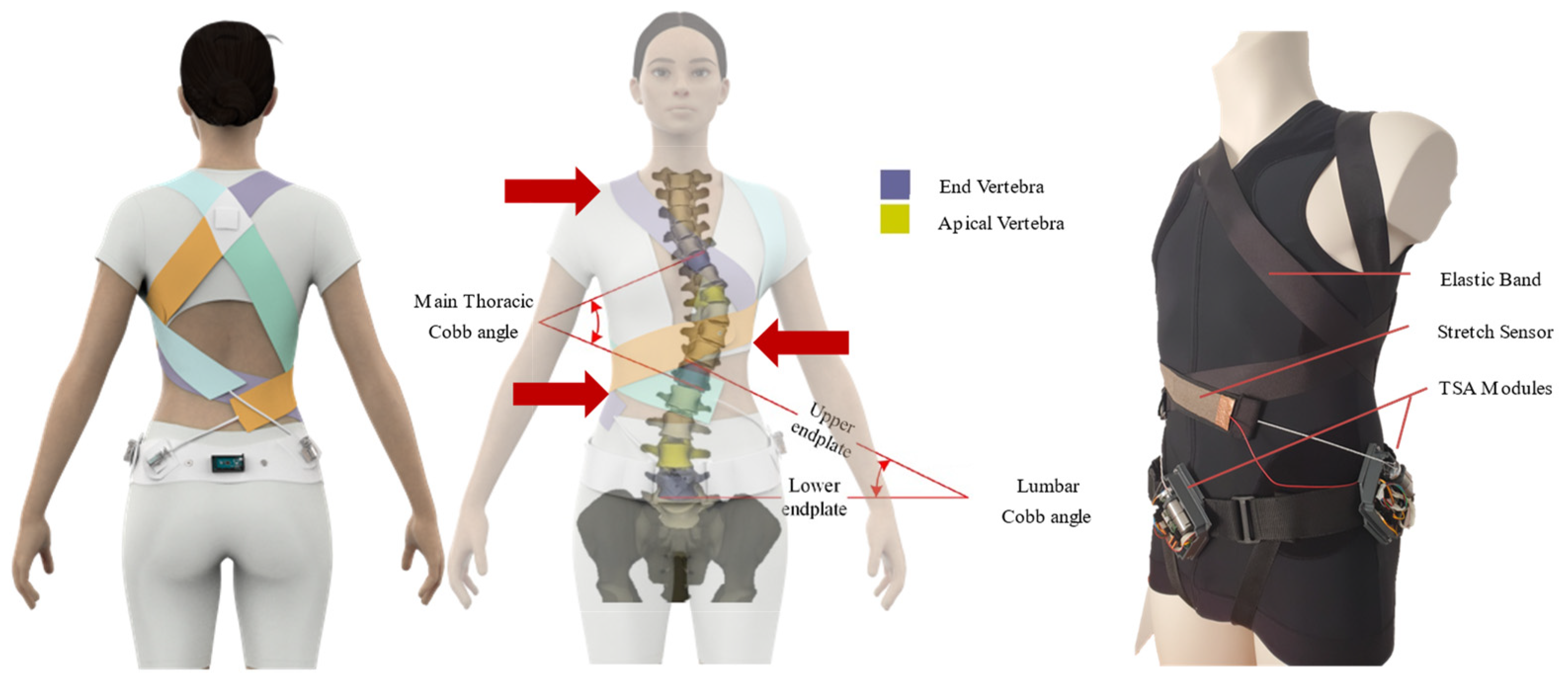
This study presents the finite element analysis of an active soft brace installed on a FE model of a scoliotic spine. A finite element model of spine is developed and validated with in vitro study to analyse the brace action. The material properties for the brace fabric are chosen based on a study performed on different fabric materials for soft braces to allow maximum air permeability, better comfort and maximum effectiveness in scoliosis treatment [23]. The mechanical functioning principle and the validation of the actuation mechanism model of the active soft brace have been previously published in [24]. The active soft brace applies forces in the form of elastic resistance. These forces can be controlled using a low-power light-weight twisted string actuation mechanism (see Figure 1).
The objective of this article is to use a FE model, derived from computed tomography (CT) data of a thoracolumbar spine and ribcage of a scoliosis patient, to investigate the mechanisms of the active soft brace. The question of interest is how the scoliosis, especially the Cobb angle, is reduced with different magnitudes of corrective forces applied by the active soft brace. This study mainly focuses on the validation of the proof of concept of active soft brace in terms of its mechanical working and how it can be used to regulate the forces. Additionally, the ability of the FE model to predict the contact pressure between the brace and trunk was used to evaluate the scoliosis correction for different tensions in the elastic bands of the active soft brace.
The article is organized into two parts. The first part describes the finite element modelling of the spine and its validation, while the second part is on the evaluation of the active soft brace action.
2. Finite Element Modelling of Scoliotic Spine
The primary part of the finite element analysis is to create a geometry as close as possible to the real human trunk. One of the main obstacles in modelling the biomechanics of the human body with FEM is the geometric complexity of the component structures within the body. One of the critical challenges in FEM studies is the computational power required to run the simulations. This is directly related to the number of nodes and elements that generate the model. The higher the number of nodes and elements in a model, the greater the demand for processing time and computational power. This complexity also leads to convergence problems during simulation [25]. Therefore, instead of modelling the skeleton as a solid body, using the beam shell approach significantly reduces the computational power and complexity.
2.1. Model Geometry
The model used in this study was generated from the open-source CT scans of a female patient [26]. Cobb and Kyphosis angles were calculated according to [27]; the main thoracic Cobb angle is 20.2 degrees and the Kyphosis angle is 26 degrees. The STL geometry file was imported into the Ansys workbench (Canonsburg, PA, USA) (see Figure 2). Due to the high geometric complexity of the pelvis, sacrum, and scapula, it was not feasible to model these either as beam or shell elements. Therefore, these parts were modelled as 3D solid parts. Each part was imported in Ansys SpaceClaim, and the mesh facet was coarsened to an acceptable amount. These parts were converted to solid structures through the “skin attach” function. The vertebrae were modelled as 3D elastic beams, whereas ribs, sternum, manubrium, and costal cartilages were modelled as 3D shell elements.
2.2. Modelling Vertebrae
Vertebrae were modelled as 3D beam elements. For each vertebra, six points coordinates (vertebra start, middle point, endpoint, transverse process 1, transverse process 2, spinous process) were extracted from the source STL file using point conversion (see Figure 3a). Five other parameters (vertebra equivalent radius, transverse process width, transverse process height, spinous process width, and spinous process height) were also extracted from these models. It was important to calculate an equivalent cross-section, start, midpoint, and endpoint for each vertebra to model them as beam elements. The three processes equivalent area and length were extracted from the centre of each vertebra, to act as a geometric reference for further addition of ligaments to the model. All these parameters were saved as a CSV file. This CSV file was imported into the Ansys geometry, where sections were applied to them to convert them into 3D beams.
2.3. Modelling Ribs, Costal Cartilages, Sternum & Manubrium
Ribs, Costal cartilages, Sternum and Manubrium were modelled as 3D shell elements. Each rib boundary curve was first exported into SolidWorks as points and a surface was extruded through the points. In Ansys, thickness was applied to these surfaces to convert them to shell elements (see Figure 3b). The costal cartilages are bars of hyaline cartilage. They allow the ribs forward movement contributing towards the flexibility of the thoracic wall. The method used for modelling the costal cartilage was the same as that in [14], i.e., 3D elastic shell elements connecting 7 top ribs to the sternum sides. Sternum and manubrium were also modelled as 3D shell elements with the same procedure performed for ribs.
2.4. Material Properties
In performing a finite element analysis on the brace operation, material properties play a significant role. The material properties and element type for each part are described in Table 1 and Table 2. After the definition of the material library, the thickness of surface bodies and cross-sections of beam bodies are defined in the Ansys design modeler. Sections were defined for beam structures, i.e., clavicle, vertebra, and processes. Sections were applied to the respective parts and a virtual section plot is used to check the geometry, as shown in Figure 2c.

Table 1.
Material Properties of FE Model.
| Anatomical Structure | Element Type | Material Parameters | References |
|---|---|---|---|
| Costal cartilage | 4-node shell | Linear elastic E = 490 MPa, ν = 0.4 | [28] |
| Ribs | 4-node shell | Linear elastic E = 5000 MPa, ν = 0.1 | [19] |
| Sternum/ Manubrium | 4-node shell | Linear elastic E = 9860 MPa, ν = 0.3 | [28] |
| Vertebral body | 2-node beam | Linear elastic E = 12,000 MPa, ν = 0.3 | [19] |
| Facet joints | Linear/Torsional spring | TABLE III | [29] |
| Intervertebral discs | Linear/Torsional spring | TABLE III | [29] |
| Costo-vertebral joints | 4-node shell | Linear elastic E = 5000 MPa, ν = 0.2 | [30] |
| Inter-costal connections | 2-node, tension-only connector | Linear elastic, E = 25 MPa | [31] |
| Vertebral posterior elements | 2-node beam | Quasi-rigid | [14] |
| Thoracic and abdominal soft tissues | 4-node shell | Linear elastic E = 0.55 MPa, ν = 0.45 | [32] |
| Pelvis | 3D solid | Linear elastic E = 5000 MPa, ν = 0.2 | [33] |
| Sacrum | 3D solid | Linear elastic E = 5000 MPa, ν = 0.2 | [30] |
| Scapula | 3D solid | Linear elastic E = 5000 MPa, ν = 0.2 | [30] |
| Clavicle | 2-node beam | Linear elastic E = 5000 MPa, ν = 0.2 | [30] |
| Brace (Polyester: 70%, Rubber thread: 30%) | 4-node shell | Linear elastic E = 113 MPa, ν = 0.05, thickness=1.4 mm | [23] |
Table 2 describes the types of the elements i.e., beam, solid and shell their behaviour theory.
2.5. Modelling Discs and Ligaments
Discs and ligaments were modelled through APDL (Ansys Parametric Design Language) snippet. All nodes between each vertebral body and between each vertebra spinous processes were extracted. These nodes were used to define ligament stiffness and disc stiffness. Modified beam elements were used to model intervertebral discs. The mechanical properties were set in a way to differentiate the bending and torsion behaviour to incorporate the torsional effects of the disc fibres. A correlation with the beam theory permitted the Young’s modulus to be stated as a function of the bending disc stiffness [29]. Stiffness values were initially defined based on the literature [29] and adjusted further to fit the range of motion of in vitro experiment. In Table 3, linear and torsional spring constants for each disc and ligament are listed.
2.6. Boundary Conditions
Joints and contacts are used to fully define the structure for a successful static non-linear analysis. Clavicles to scapula connections are modelled as revolute joints, allowing the scapula to rotate around the clavicle. Pelvic and sacrum are fixed together without any relative displacement between them. Moreover, the sacrum is used as the reference and fixed to the ground. The first thoracic vertebra was only allowed to move along vertical axis and its translation was blocked in transverse plane [12,29,33].
The trunk is connected to the ribs’ surface via contact elements. The outermost points of the vertebra processes and scapula top surfaces are also set to contact mode with the trunk. The method used to define the contacts between trunk and the skeleton is similar to Perie et al. [33].
Brace bands are allowed to slide over each other and the trunk surface with the frictional coefficient 0.3. Brace surfaces are defined as contact and the projected trunk surface as target. The non-linearities caused by large deformations and contact elements (status change) were also considered. The FE analysis was solved using Ansys student 2021 R1 (Canonsburg, PA, USA).
2.7. Elements Meshing
The model had a large number of friction-based nonlinear contact elements which would increase the computation time exponentially. Therefore, meshing element sizing was employed, for each part to vary according to its complexity and stiffness. Table 4 shows the element sizes used for each part of the structure. The model consists of three major parts, i.e., skeleton, trunk and brace. After applying the mesh, the model was composed of a large number of nodes and elements. The skeleton consists of 25,068 nodes and 17,424 elements, while the trunk consists of 33,908 nodes, 25,892 elements. The brace has 11,879 nodes and 10,946 elements.
3. Validation of the Spine Modelling Approach
The spinal column is a very complex structure, which allows mobility in three directions: axial rotation, lateral bending, and flexion/extension. The human spine experiences complex dynamic loading conditions during daily activities. Understanding the response of the spine under these loads will enhance our understanding of spine biomechanics and help validate spinal FE models. A considerably better controlled environment is available for the study of biomechanical properties of the spine during in vitro experiments. Motion between the vertebrae and the calculation of the loads on vertebrae is virtually unrestricted during these studies. Data extracted from in vitro experiments could be helpful for the generation of multibody models of the spine and the validation of finite element models [34].
The behaviour of the whole spinal column is an outcome of the functions of its regions (lumbar, thoracic, and cervical). Each region has its dominant function in a certain direction and behaves differently during the motion. The difference in the motion behaviour is mainly due to the difference in the stiffness of various ligaments, intervertebral disc properties, shape and orientation of different facet joints.
The FE model of scoliotic spine developed in this study is validated by dividing the spine into four different segments. Each segment contained three intervertebral discs and four vertebrae, i.e., T1–T4, T5–T8, T9–T12, and L1–L4. The Range of Motion (ROM) of each segment was measured in all three directions, i.e., axial rotation, lateral bending, and flexion/extension in response to a 4 Nm moment applied to one end, while the other end is fixed. The results were compared to a range of motions calculated from in vitro study [35].
3.1. Definition of Coordinate System and ROM
A pure moment in the +/− Mx direction represents the lateral bending to right/left. A pure moment in +/− My direction is flexion/extension; and a pure moment in +/− Mz direction is axial rotation left/right. The range of angular deflection between the maximum moments in negative and positive directions was defined as range of motion (ROM) (see Figure 4).
3.2. Methodology for Validation of the FE Model
In Ansys Workbench, four analysis cells were created for the different region’s loading and boundary conditions. These cells share the same model setup, element meshing, and mechanical properties (see Figure 5). In each load step, three different motion runs (flexion/extension, lateral bending, axial rotation) were performed and all of them were compared with the results from [35].
To validate the range of motion of the lumbar spine region, a 4 Nm moment was applied in both positive and negative directions at L1, while L4 remained fixed. Figure 6 shows the flexion/extension (FE/EX) loading simulations for L1–L4. To calculate ROM in degrees, the nodal coordinates of L1 and L4 were exported to excel by creating the User Defined Results and entering the LOC_DEFX, LOC_DEFY & LOC_DEFZ to get access to the coordinates of L1 and L4 and the deformation. After the solution is attained, the negative and positive coordinates of starting node of L1 and final node of L4 are generated and the angles between the negative and positive positions are measured for flexion/extension, right/left axial rotation, and right/left lateral bending. Results of both initial and final states were exported to csv, and node coordinates were sorted in three column text files containing X, Y and Z coordinates. Text files were imported into SolidWorks as point clouds. Using SolidWorks 3D sketch tool, start and end point of each vertebra are connected with lines and the initial (unloaded) and final (loaded) sketches are transferred into one file. A similar procedure is repeated for all the other three sections of the spine, i.e., T1–T4, T5–T8, and T9–T12.
3.3. Model Validation Results
The FEM model of the spine was validated by comparing the range of motion of different spinal regions with in vitro study of Busscher et al. [35]. The range of motion differed between regions and loading directions (see Figure 7). In lateral bending and flexion/extension, the different regions of the spine exhibited a similar pattern regarding ROM. Lower values of ROM were observed in the lower and middle thoracic regions, while L1–L4 and T1–T4 showed a higher range of motion. In axial rotation, the range of motion in the upper thoracic region was the largest and decreased towards caudal. The ROM in the axial rotation was expected to decrease due to differences in orientation and shape of facet joints [37]. The FE results showed a similar pattern, as measured in the in vitro study.
4. Evaluation of Active Soft Brace Effects on Spine
This section focuses on the evaluation of the mechanisms of the active soft brace. This section demonstrates how, by varying the tensions in the elastic bands, contact pressure exerted by the brace can be regulated, and how active soft brace can provide thoracic rotation, shoulder rotation and lateral bending, resulting in immediate brace correction.
The brace exerts forces in the form of elastic resistance using four 50 mm wide elastic bands. The purpose of elastic bands is to provide shoulder rotation, thoracic rotation, and lateral bending. Pulling forces (FA to FD) of different magnitudes are applied at end of the elastic bands to simulate TSAs function. This results in generating the corrective forces (F1–F8) at the key locations indicated in Figure 8.
Elastic bands are connected to the contoured vest. First left thoracic band is connected at the back of the vest and wrapped around the lower left corner of the rib cage and finally connected to the pelvic back. This band provides thoracic rotation in a clockwise direction and attaches to the twisted string actuator using Velcro clips. TSAs is used to adjust the tension in the elastic band to keep the spine at the correct de-rotated posture. The second band (right thoracic) starts from the back passes through right thoracic based, wrapped around the abdominal part and goes all the way to left half of the pelvic back. The tension in the band is kept bit lower compared to the left thoracic band to keep the spine rotated in the clockwise direction. The difference between the tensions (FA–FC) can be varied using TSA resulting in controlling the axial torques for lower thoracic rotation. If the difference between the FA and FC is varied between 0–20 N, we can generate the axial torque of 0–3.6 Nm (20 N × 0.18 m). Here, 0.18 m is the average moment arm for the scoliotic spine under study. The blue curve in Figure 9 shows the relation between the axial torque generated by varying the difference between the forces (FA–FC) and the axial rotation in degrees of the lower thoracic region. Similarly, FB and FD contribute towards the shoulder rotation, resulting in the generation of the axial toque in the upper thoracic region. This can be seen in the red line in Figure 9.
The force magnitudes (0–20 N) are chosen based on the study of contact pressure (0–8 kPa) between brace and the trunk [38]. A simulation setup was designed representing the trunk body and elastic band wrapped around it. One end of the band is fixed in space while other end is pulled with force F to simulate the twisted string actuator force. We measured the contact pressure between the body and the elastic band and observed that the 20 N pulling force would correspond to the 7.86 kPa of the contact pressure (See Figure 10). The rigid brace in [38] exerts pressure through pads in the range of 0–8 kPa at different locations of the spine. This simulation setup enabled us to demonstrate that the active soft brace can also exert pressure up to 8 kPa and the amount of pressure can be regulated using TSAs.
The third right shoulder band rotates around the rib cage and back and finally attaches in front of the pelvic belt. This band generates counterclockwise shoulder rotation and right lateral flexion at T12. This band augments the principle of three-point pressure bending. By varying the force, FD corresponds to the right shoulder band; it can be seen from Figure 11 that the right lateral flexion results in an improvement in the immediate in-brace cobb angle. The fourth left shoulder flap generates counterclockwise shoulder rotation and counterclockwise shoulder tilt, which is demonstrated in Figure 9.
The results presented in Figure 11 depict that the increase in the pulling force FD results in higher lateral bending force and improvement in the main thoracic Cobb angle. Table 5 shows that the Cobb angle correction corresponds to the change in force FD. At 20 N pulling force the brace showed 15.96% of Cobb angle correction. In scoliosis bracing, if the average in-brace correction equals >15°, then it is predicted that the result will lead to a final correction [39].
5. Discussion
Biomechanics of a scoliotic spine under active soft brace was evaluated using a FE model. The FE model was derived from the CT data of a scoliosis patient. The modelling strategy, the material and structural parameters were taken from the benchmark literature stated in Table 1. The ROM of FE model of the scoliotic spine was validated with in vitro study of a normal spine [35]. This is because the majority of the studies investigated only one region of the spine (lumbar, thoracic, or cervical). Experimental protocols and setups between the studies were quite different, which made it difficult to draw a comparison between regions [16,40,41]. This study investigated the potential use of active soft brace in correcting the Cobb angle. Although the ROMs are different in scoliotic and a normal spine, it nevertheless allowed us to demonstrate the working principle of the brace.
The FE model is simplified, to a certain extent, relative to the actual model of the human trunk for the simulation process. The FE model presented in this study is limited by certain constraints and approximations. The FEM model incorporates only passive elements of the trunk; muscle and gravitational contributions are not explicitly implemented in the model. Thus, the dynamic effect of the brace (Patient’s inclination to minimize pressure areas) cannot be directly rationalized. Viscoelastic behaviour of the soft tissues for a longer period of brace application was not considered.
Simulation was able to predict true orthopaedic condition and has the potential to optimize clinical treatment. Brace action was implemented by exerting measured contact reaction forces to selected nodes to simulate the elastic band pressure. However, without prior knowledge of the target results, this approach does not allow the prediction of the treatment action. Thus, the FE model in this study was evaluated in terms of its capability to perceive the geometric deformations of the spine due to the forces applied by the active soft brace. Although the results presented are the immediate in-brace correction, it has a clear correlation with long-term brace treatment. Chase et al. stated that there exists a correlation between the immediate correction and effectiveness with the long-term effect of brace treatment. The better a brace initially corrects the Cobb angle, the higher is its efficacy to have a positive long-term effect on the treatment [42].
Brace effectiveness with regard to muscle activity has been discussed controversially [43,44,45,46]. While some researchers assume a risk of muscle dysfunction, resulting in inducing a secondary curve evolution when bracing is stopped [44], others assume that muscle strength can be regained through physiotherapy during and after the brace treatment. Nevertheless, the present FE study does not incorporate muscle activity as stated. However, correlations between instantaneous in-brace correction and the long-term effect of bracing have been reported [45,46]. Dynamic analysis by merging musculoskeletal modelling using the AnyBody Modelling System™, Boston, MA, USA and FE models could be carried out in the future to obtain a better understanding of active soft brace.
The implementation of the model in the simulation platform enabled us to investigate the contact reaction between the trunk and the brace. This allowed us to adjust the tensions in the elastic bands to obtain a better corrective effect. Through the effective realization of how the patient’s spine mechanics is changed, finite element models can potentially offer a better understanding of how to attain an optimal correction for an individual patient’s spine.
6. Conclusions
This article presents an active soft brace which applies corrective forces in the form of elastic resistance while allowing the mobility to the spine to treat scoliosis. The study focuses on demonstrating the working principle of the active soft brace using a FE model of the human trunk. This study also aimed to understand whether the amount of force and pressure that active soft brace exerts is in the acceptable range. The trunk model was validated by comparing the range of motion of different sections of the spine with in vitro study. In-brace correction has been demonstrated in terms of thoracic rotation, shoulder rotation and lateral bending with variation in the forces exerted by the TSAs. It can be concluded from the results that by varying the tension in the elastic bands, the Cobb angle in both the coronal and sagittal planes can be improved. Brace can provide shoulder rotation thoracic rotation and lateral bending forces. The brace was able to provide the correction of 15.96° to the main thoracic cobb angle with variation in tension in the elastic band using TSAs. If the average in-brace correction equals >15°, it is predicted that it will result in final correction of the Cobb angle. The amount of pressure that the brace can regulate is within the acceptable range of the pressure (0–8 kPa) that the rigid braces usually exert. In conclusion, this study provided a pathway to the development of an active soft brace to treat scoliosis, while overcoming the issues associated with static, passive, and rigid bracing.
Author Contributions
The Conceptualization, methodology, investigation, resources, data curation, writing—original draft preparation, A.A.; writing—review and editing, V.F., W.S., S.K.A.; visualization, supervision V.F., W.S.; project administration, funding acquisition, V.F. All authors have read and agreed to the published version of the manuscript.
Funding
This project has received funding from the Italian Ministry for Education, University, and Research (MIUR) through the “Departments of Excellence” program.
Acknowledgments
We acknowledge the mentoring of Marco Fontana in this project and his efforts for funding acquisition.
Conflicts of Interest
The authors declare that the research was conducted in the absence of any commercial or financial relationships that could be construed as a potential conflict of interest.
References
- Ogilvie, J. Adolescent idiopathic scoliosis and genetic testing. Curr. Opin. Pediatr. 2010, 22, 67–70. [Google Scholar] [CrossRef] [PubMed]
- Nachemson, A.L.; Peterson, L.E. Effectiveness of treatment with a brace in girls who have adolescent idiopathic scoliosis. A prospective, controlled study based on data from the Brace Study of the Scoliosis Research Society. J. Bone Jt. Surg. Am. 1995, 77, 815–822. [Google Scholar] [CrossRef] [PubMed]
- Lonstein, J.E.; Winter, R.B. The Milwaukee brace for the treatment of adolescent idiopathic scoliosis. A review of one thousand and twenty patients. J. Bone Jt. Surg. 1994, 76, 1207–1221. [Google Scholar] [CrossRef] [PubMed]
- Périé, D.; Aubin, C.-E.; Petit, Y.; Beauséjour, M.; Dansereau, J.; Labelle, H. Boston Brace Correction in Idiopathic Scoliosis: A Biomechanical Study. Spine 2003, 28, 1672–1677. [Google Scholar] [CrossRef] [PubMed]
- Wiemann, J.M.; Shah, S.A.; Price, C.T. Nighttime Bracing Versus Observation for Early Adolescent Idiopathic Scoliosis. J. Pediatr. Orthop. 2014, 34, 603–606. [Google Scholar] [CrossRef] [Green Version]
- De Giorgi, S.; Piazzolla, A.; Tafuri, S.; Borracci, C.; Martucci, A.; De Giorgi, G. Chêneau brace for adolescent idiopathic scoliosis: Long-term results. Can it prevent surgery? Eur. Spine J. 2013, 22, 815–822. [Google Scholar] [CrossRef] [PubMed] [Green Version]
- De Mauroy, J.C.; Lecante, C.; Barral, F.; Daureu, D.; Gualerzi, S.; Gagliano, R. The Lyon Brace. Disabil. Rehabil. 2008, 3, 139–145. [Google Scholar] [CrossRef]
- Gutman, G.; Benoit, M.; Joncas, J.; Beauséjour, M.; Barchi, S.; Labelle, H.; Parent, S.; Mac-Thiong, J.-M. The effectiveness of the SpineCor brace for the conservative treatment of adolescent idiopathic scoliosis. Comparison with the Boston brace. Spine J. 2016, 16, 626–631. [Google Scholar] [CrossRef]
- Veldhuizen, A.G.; Cheung, J.; Bulthuis, G.J.; Nijenbanning, G. A new orthotic device in the non-operative treatment of idiopathic scoliosis. Med. Eng. Phys. 2002, 24, 209–218. [Google Scholar] [CrossRef]
- Ali, A.; Fontanari, V.; Fontana, M.; Schmölz, W. Spinal Deformities and Advancement in Corrective Orthoses. Bioengineering 2020, 8, 2. [Google Scholar] [CrossRef]
- Wong, M.S.; Cheng, J.; Lam, T.P.; Ng, B.K.W.; Sin, S.W.; Lee-Shum, S.L.F.; Chow, H.K.D.; Tam, S.Y.P. The Effect of Rigid Versus Flexible Spinal Orthosis on the Clinical Efficacy and Acceptance of the Patients with Adolescent Idiopathic Scoliosis. Spine 2008, 33, 1360–1365. [Google Scholar] [CrossRef] [PubMed]
- Clin, J.; Aubin, C.-E.; Parent, S.; Sangole, A.; Labelle, H. Comparison of the biomechanical 3D efficiency of different brace designs for the treatment of scoliosis using a finite element model. Eur. Spine J. 2010, 19, 1169–1178. [Google Scholar] [CrossRef] [PubMed] [Green Version]
- Cobetto, N.; Aubin, C.É.; Parent, S.; Barchi, S.; Turgeon, I.; Labelle, H. 3D correction of AIS in braces designed using CAD/CAM and FEM: A randomized controlled trial. Scoliosis Spinal Disord. 2017, 12, 24. [Google Scholar] [CrossRef] [PubMed] [Green Version]
- Little, J.P.; Izatt, M.T.; Labrom, R.D.; Askin, G.N.; Adam, C.J. An FE investigation simulating intra-operative corrective forces applied to correct scoliosis deformity. Scoliosis 2013, 8, 9. [Google Scholar] [CrossRef] [Green Version]
- Desbiens-Blais, F.; Clin, J.; Parent, S.; Labelle, H.; Aubin, C.-E. New brace design combining CAD/CAM and biomechanical simulation for the treatment of adolescent idiopathic scoliosis. Clin. Biomech. 2012, 27, 999–1005. [Google Scholar] [CrossRef]
- Dreischarf, M.; Zander, T.; Shirazi-Adl, A.; Puttlitz, C.M.; Adam, C.J.; Chen, C.S.; Goel, V.K.; Kiapour, A.; Kim, Y.H.; Labus, K.M.; et al. Comparison of eight published static finite element models of the intact lumbar spine: Predictive power of models improves when combined together. J. Biomech. 2014, 47, 1757–1766. [Google Scholar] [CrossRef] [Green Version]
- El Bojairami, I.; El-Monajjed, K.; Driscoll, M. Development and validation of a timely and representative finite element human spine model for biomechanical simulations. Sci. Rep. 2020, 10, 21519. [Google Scholar] [CrossRef]
- Vergari, C.; Ribes, G.; Aubert, B.; Adam, C.J.; Miladi, L.; Ilharreborde, B.; Abelin-Genevois, K.; Rouch, P.; Skalli, W. Evaluation of a Patient-Specific Finite-Element Model to Simulate Conservative Treatment in Adolescent Idiopathic Scoliosis. Spine Deform. 2015, 3, 4–11. [Google Scholar] [CrossRef] [Green Version]
- Guan, T.; Zhang, Y.; Anwar, A.; Zhang, Y.; Wang, L. Determination of Three-Dimensional Corrective Force in Adolescent Idiopathic Scoliosis and Biomechanical Finite Element Analysis. Front. Bioeng. Biotechnol. 2020, 8, 963. [Google Scholar] [CrossRef]
- Jalalian, A.; Tay, F.E.H.; Arastehfar, S.; Liu, G. A new method to approximate load–displacement relationships of spinal motion segments for patient-specific multi-body models of scoliotic spine. Med. Biol. Eng. Comput. 2017, 55, 1039–1050. [Google Scholar] [CrossRef]
- Park, J.-H.; Stegall, P.R.; Roye, D.P.; Agrawal, S.K. Robotic Spine Exoskeleton (RoSE): Characterizing the 3-D Stiffness of the Human Torso in the Treatment of Spine Deformity. IEEE Trans. Neural Syst. Rehabil. Eng. 2018, 26, 1026–1035. [Google Scholar] [CrossRef]
- Berteau, J.-P.; Pithioux, M.; Mesure, S.; Erard Bollini, G.; Chabrand, P. Beyond the classic correction system: A numerical nonrigid approach to the scoliosis brace. Spine J. 2011, 11, 424–431. [Google Scholar] [CrossRef]
- Hui, C.-L.; Piao, J.; Wong, M.S.; Chen, Z. Study of Textile Fabric Materials used in Spinal Braces for Scoliosis. J. Med. Biol. Eng. 2020, 40, 356–371. [Google Scholar] [CrossRef]
- Ali, A.; Fontanari, V.; Fontana, M.; Schmölz, W. Soft Active Dynamic Brace for Spinal Deformities. In Proceedings of the 14th International Joint Conference on Biomedical Engineering Systems and Technologies (BIOSTEC 2021), Online. 11–13 February 2021; pp. 169–174. [Google Scholar] [CrossRef]
- Jalalian, A.; Gibson, I.; Tay, E.H. Computational Biomechanical Modeling of Scoliotic Spine: Challenges and Opportunities. Spine Deform. 2013, 1, 401–411. [Google Scholar] [CrossRef] [PubMed]
- Sketchfab. Scoliosis Model Female. Available online: https://sketchfab.com/3d-models/scoliosis-b13dc14becfc4a16b8229f5ef9ac3603 (accessed on 27 January 2021).
- Jalalian, A. A Patient-Specific Multibody Model of Scoliotic Spine for Surgical Correction Prediction in the Coronal Plane. Ph.D. Thesis, National University of Singapore, Singapore, 2016. [Google Scholar]
- Kimpara, H.; Lee, J.B.; Yang, K.H.; King, A.I.; Iwamoto, M.; Watanabe, I.; Miki, K. Development of a three-dimensional finite element chest model for the 5th percentile female. Stapp Car Crash J. 2005, 49, 251. [Google Scholar]
- Lafage, V.; Dubousset, J.; Lavaste, F.; Skalli, W. 3D finite element simulation of Cotrel–Dubousset correction. Comput. Aided Surg. 2004, 9, 17–25. [Google Scholar] [CrossRef]
- Nie, W.-Z.; Ye, M.; Liu, Z.-D.; Wang, C.-T. The Patient-Specific Brace Design and Biomechanical Analysis of Adolescent Idiopathic Scoliosis. J. Biomech. Eng. 2009, 131, 041007. [Google Scholar] [CrossRef] [PubMed]
- Stokes, I.; Laible, J.P. Three-dimensional osseo-ligamentous model of the thorax representing initiation of scoliosis by asymmetric growth. J. Biomech. 1990, 23, 589–595. [Google Scholar] [CrossRef]
- Rey, J.; Bischo, E.; Arruda, E.M.; Grosh, K. Finite element modeling of human skin using an isotropic, nonlinear elastic constitutive model. J. Biomech. 2000, 33, 645–652. [Google Scholar]
- Perie, D.; Aubin, C.E.; Lacroix, M.; Lafon, Y.; Labelle, H. Biomechanical modelling of orthotic treatment of the scoliotic spine in-cluding a detailed representation of the brace-torso interface. Med. Biol. Eng. Comput. 2004, 42, 339–344. [Google Scholar] [CrossRef]
- Guan, Y.; Yoganandan, N.; Moore, J.; Pintar, F.A.; Zhang, J.; Maiman, D.J.; Laud, P. Moment–rotation responses of the human lumbosacral spinal column. J. Biomech. 2007, 40, 1975–1980. [Google Scholar] [CrossRef] [PubMed]
- Busscher, I.; van Dieën, J.H.; Kingma, I.; van der Veen, A.J.; Verkerke, G.J.; Veldhuizen, A.G. Biomechanical characteristics of different regions of the human spine: An in vitro study on multilevel spinal segments. Spine 2009, 34, 2858–2864. [Google Scholar] [CrossRef] [PubMed]
- Wilke, H.-J.; Wenger, K.; Claes, L. Testing criteria for spinal implants: Recommendations for the standardization of in vitro stability testing of spinal implants. Eur. Spine J. 1998, 7, 148–154. [Google Scholar] [CrossRef] [PubMed] [Green Version]
- Masharawi, Y.; Rothschild, B.; Dar, G.; Peleg, S.; Robinson, D.; Been, E.; Hershkovitz, I. Facet Orientation in the Thoracolumbar Spine: Three-dimensional Anatomic and Biomechanical Analysis. Spine 2004, 29, 1755–1763. [Google Scholar] [CrossRef] [PubMed]
- Pham, V.M.; Houilliez, A.; Schill, A.; Carpentier, A.; Herbaux, B.; Thevenon, A. Study of the pressures applied by a Chêneau brace for correction of adolescent idiopathic scoliosis. Prosthet. Orthot. Int. 2008, 32, 345–355. [Google Scholar] [CrossRef] [Green Version]
- Weiss, H.-R.; Turnbull, D.; Bohr, S. Brace treatment for patients with Scheuermann’s disease—A review of the literature and first experiences with a new brace design. Scoliosis 2009, 4, 22. [Google Scholar] [CrossRef] [PubMed] [Green Version]
- Panjabi, M.M.; Oxland, T.R.; Yamamoto, I.; Crisco, J.J. Mechanical behavior of the human lumbar and lumbosacral spine as shown by three-dimensional load-displacement curves. J. Bone Jt. Surg. 1994, 76, 413–424. [Google Scholar] [CrossRef] [PubMed]
- Crisco, J.J.; Fujita, L.; Spenciner, D.B. The dynamic flexion/extension properties of the lumbar spine in vitro using a novel pendulum system. J. Biomech. 2007, 40, 2767–2773. [Google Scholar] [CrossRef] [PubMed]
- Edgar, M.; Mehta, M. Long-term follow-up of fused and unfused idiopathic scoliosis. J. Bone Jt. Surg. Br. Vol. 1988, 70-B, 712–716. [Google Scholar] [CrossRef]
- Weiss, H.-R.; Negrini, S.; Hawes, M.C.; Rigo, M.; Kotwicki, T.; Grivas, T.B.; Maruyama, T.; Members of the of the SOSORT. Physical exercises in the treatment of idiopathic scoliosis at risk of brace treatment—SOSORT consensus paper 2005. Scoliosis 2006, 1, 6. [Google Scholar] [CrossRef] [Green Version]
- de Sèze, M.; Cugy, E. Pathogenesis of idiopathic scoliosis: A review. Ann. Phys. Rehabil. Med. 2012, 55, 128–138. [Google Scholar] [CrossRef] [PubMed] [Green Version]
- Clin, J.; Aubin, C.; Sangole, A.; Labelle, H.; Parent, S. Correlation Between Immediate In-Brace Correction and Biomechanical Effectiveness of Brace Treatment in Adolescent Idiopathic Scoliosis. Spine 2010, 35, 1706–1713. [Google Scholar] [CrossRef] [PubMed]
- Castro, F.P. Adolescent idiopathic scoliosis, bracing, and the Hueter-Volkmann principle. Spine J. 2003, 3, 180–185. [Google Scholar] [CrossRef]
Figure 1.
Soft active brace prototype and conceptual design.

Figure 2.
Modelling geometry of scoliotic spine. (a) stl file from the tomography (b) beam shell model with vertebra measurement. (c) FE model with virtual sections (d) complete FE model with brace.
Figure 2.
Modelling geometry of scoliotic spine. (a) stl file from the tomography (b) beam shell model with vertebra measurement. (c) FE model with virtual sections (d) complete FE model with brace.

Figure 3.
(a) Vertebra Modelling and Measurements (b) (Left) Fitting point and line curves to each rib on solid geometry (Right) Converting rib guided curves into surfaces.
Figure 3.
(a) Vertebra Modelling and Measurements (b) (Left) Fitting point and line curves to each rib on solid geometry (Right) Converting rib guided curves into surfaces.

Figure 4.
Three-dimensional coordinate system description according to ISO 2631. The arrows of the motion components ∆x, ∆y, ∆z, ∆α, ∆β, ∆γ denote the positive direction [36].
Figure 4.
Three-dimensional coordinate system description according to ISO 2631. The arrows of the motion components ∆x, ∆y, ∆z, ∆α, ∆β, ∆γ denote the positive direction [36].

Figure 5.
Ansys analysis cells for loading and boundary conditions of validation setup.

Figure 6.
ROM measurement for FE/EX L1–L4 loading (Moment on L1 while L4 fixed in space).

Figure 7.
Range of motion validation for flexion/extension, lateral bending, and axial rotation.

Figure 8.
(a,b) Depiction of pulling force and (c) contact reaction force for the simulation.

Figure 9.
Demonstration of upper and lower thoracic rotation exerted by active soft brace.

Figure 10.
Pulling forces and contact pressure relation.

Figure 11.
Improvement in Cobb angle with increase in lateral force by varying the tension in shoulder right band (FD).
Figure 11.
Improvement in Cobb angle with increase in lateral force by varying the tension in shoulder right band (FD).

Table 2.
ANSYS element types used in this study.
| Item | Element | Behaviour |
|---|---|---|
| Vertebrae | Beam 188 | Timoshenko beam theory |
| Vertebrae processes | Beam 188 | Timoshenko beam theory |
| Vertebrae discs | Combin14 | Linear spring-damper |
| Ligaments | Combin14 | Linear spring-damper |
| Pelvis | Solid 186 | Homogeneous Structural Solid |
| Sacrum | Solid 186 | Homogeneous Structural Solid |
| Clavicle | Beam 188 | Timoshenko beam theory |
| Scapula | Solid 186 | Homogeneous Structural Solid |
| Sternum | Shell 181 | Kirchhoff plate theory |
| Rib | Shell 181 | Kirchhoff plate theory |
| Costal cartilage | Shell 181 | Kirchhoff plate theory |
| Trunk | Shell 181 | Kirchhoff plate theory |
| Brace | Shell 181 | Kirchhoff plate theory |
Table 3.
Ligament properties.
| Vertebra | Ligament Stiffness (N/mm) | v | E (MPa) | K Torsional (Nm/deg) |
|---|---|---|---|---|
| T1/T2 | 185 | 0.45 | 3.4 | 0.49 |
| T2/T3 | 311 | 0.45 | 3.4 | 0.49 |
| T3/T4 | 259 | 0.45 | 3.4 | 0.49 |
| T4/T5 | 174 | 0.45 | 3.4 | 0.49 |
| T5/T6 | 158 | 0.45 | 3.4 | 1.05 |
| T6/T7 | 139 | 0.45 | 3.4 | 1.05 |
| T7/T8 | 144 | 0.45 | 3.4 | 1.05 |
| T8/T9 | 137 | 0.45 | 3.4 | 1.05 |
| T9/T10 | 121 | 0.45 | 5 | 4.54 |
| T10/T11 | 93 | 0.45 | 5 | 4.54 |
| T11/T12 | 69 | 0.45 | 5 | 4.54 |
| T12/L1 | 57 | 0.45 | 5 | 4.54 |
| L1/L2 | 27 | 0.45 | 5 | 8.37 |
| L2/L3 | 20 | 0.45 | 5 | 8.37 |
| L3/L4 | 16 | 0.45 | 5 | 8.37 |
| L4/L5 | 18 | 0.45 | 5 | 8.37 |
| L5/S1 | 40 | 0.45 | 5 | 8.37 |
Table 4.
Meshing size of different parts of the model.
| Item | Element Size | Nodes | Elements |
|---|---|---|---|
| Scapula | 10 mm | 25,068 | 17,424 |
| Pelvic | Rigid | ||
| Sacrum | Rigid | ||
| Vertebra | 5 mm | ||
| Rib | 5 mm | ||
| Clavicle | 5 mm | ||
| Trunk | 10 mm | 33,908 | 25,892 |
| Brace | 10 mm | 11,879 | 10,946 |
Table 5.
Cobb angle correction corresponds to pulling force FD.
| Force FD (N) | Main Thoracic Cobb Angle | Kyphosis Angle |
|---|---|---|
| 5 | 4.31° | 3.24° |
| 10 | 11.48° | 6.15° |
| 15 | 14.35° | 11.51° |
| 20 | 15.96° | 12.48° |
Publisher’s Note: MDPI stays neutral with regard to jurisdictional claims in published maps and institutional affiliations. |
© 2022 by the authors. Licensee MDPI, Basel, Switzerland. This article is an open access article distributed under the terms and conditions of the Creative Commons Attribution (CC BY) license (https://creativecommons.org/licenses/by/4.0/).
Share and Cite
MDPI and ACS Style
Ali, A.; Fontanari, V.; Schmölz, W.; Agrawal, S.K. Active Soft Brace for Scoliotic Spine: A Finite Element Study to Evaluate in-Brace Correction. Robotics 2022, 11, 37. https://doi.org/10.3390/robotics11020037
AMA Style
Ali A, Fontanari V, Schmölz W, Agrawal SK. Active Soft Brace for Scoliotic Spine: A Finite Element Study to Evaluate in-Brace Correction. Robotics. 2022; 11(2):37. https://doi.org/10.3390/robotics11020037
Chicago/Turabian StyleAli, Athar, Vigilio Fontanari, Werner Schmölz, and Sunil K. Agrawal. 2022. "Active Soft Brace for Scoliotic Spine: A Finite Element Study to Evaluate in-Brace Correction" Robotics 11, no. 2: 37. https://doi.org/10.3390/robotics11020037
Note that from the first issue of 2016, this journal uses article numbers instead of page numbers. See further details here.