
Feasibility and Performance Validation of a Leap Motion Controller for Upper Limb Rehabilitation


1
Federal Institute of Espírito Santo (IFES), Vitória 29173-087, Brazil
2
School of Mechanical Engineering, Federal University of Uberlândia, Uberlândia 38408-016, Brazil
3
Department of Mechanical, Energy, and Management Engineering, University of Calabria, 87036 Cosenza, Italy
*
Author to whom correspondence should be addressed.
Robotics 2021, 10(4), 130; https://doi.org/10.3390/robotics10040130
Submission received: 3 November 2021
/
Revised: 24 November 2021
/
Accepted: 28 November 2021
/
Published: 4 December 2021
(This article belongs to the Special Issue 10th Anniversary of Robotics—Feature Papers in Intelligent Robots and Mechatronics)
Abstract
:The leap motion controller is a commercial low-cost marker-less optical sensor that can track the motion of a human hand by recording various parameters. Upper limb rehabilitation therapy is the treatment of people having upper limb impairments, whose recovery is achieved through continuous motion exercises. However, the repetitive nature of these exercises can be interpreted as boring or discouraging while patient motivation plays a key role in their recovery. Thus, serious games have been widely used in therapies for motivating patients and making the therapeutic process more enjoyable. This paper explores the feasibility, accuracy, and repeatability of a leap motion controller (LMC) to be applied in combination with a serious game for upper limb rehabilitation. Experimental feasibility tests are carried out by using an industrial robot that replicates the upper limb motions and is tracked by using an LMC. The results suggest a satisfactory performance in terms of tracking accuracy although some limitations are identified and discussed in terms of measurable workspace.
1. Introduction
Stroke is a leading cause of long-term disability and leaves a significant number of individuals with cognitive and motor deficits. The most frequent consequence of stroke is the paralysis of the upper limb, as mentioned, for example, in [1,2,3]. Rehabilitation training is the most effective way to reduce motor impairments in stroke patients and robots can be suited for this purpose, since they can train patients for long durations with high accuracy [4,5,6]. Effective stroke rehabilitation should be early, intense, and repetitive, which can lead to problems with motivation and patient involvement, since conventional rehabilitation therapy is often monotonous and repetitive [7]. A new paradigm is emerging in the rehabilitation field characterized by the systematic use of serious games [8]. Serious games aim to provide a truly interactive rehabilitation experience and generate a high level of motivation in patients. The rehabilitation using serious games are more attractive softening the notion of effort during the exercises [9].
A leap motion controller has been preliminarily proposed in combination with serious games for upper limb rehabilitation, such as outlined in [10,11,12,13,14]. However, the proposed applications lack a reliable information on the expected performance of leap motion controllers when applied to specific rehabilitation tasks within serious games interactive environments.
The paper is structured as follows: Section 2 provides a critical review on the specifications for a LMC followed by a brief review on the kinesiology and rehabilitation of upper limb. The methodology of experiments is presented in Section 4. The detailed results are analyzed and discussed in Section 5. Finally, key conclusions and recommendations are drawn in Section 6.
2. A Critical Review on the Specifications for a Leap Motion Controller
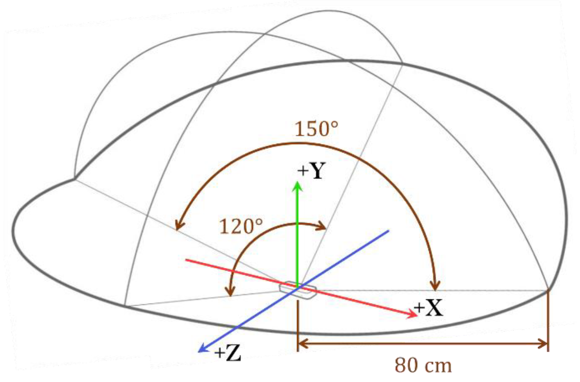
The leap motion controller (LMC) was launched in 2012. The significance of using a LMC is based on its features in terms of low-cost and robustness. Note that a LMC costs an average of USD 100, and it is an off-the-shelf product that can be easily purchased worldwide. The device has a workspace that is shown in Figure 1. It consists of two cameras and three infrared LEDs. Its operation is based on the principle of stereoscopy. The images obtained by the cameras are recorded and buffered in its internal memory to be later transmitted via an USB interface to the tracking software [15,16]. Information is obtained from the images collected by the cameras such as position and orientation of the fingertips and palm of the hand.
The Cartesian reference system used by the LMC originates from the center of its upper surface and orientation as shown in Figure 1. The processing of the LMC data taken from the images is done by the application programmer interface (API) that provides a set of functions that can be accessed to obtain the parameters calculated from the sensor. The possible parameters to be extracted, and the methods used in their calculation depend on the version of the Software Development Kit (SDK). In its first version, finger tracking was not as efficient, with problems such as finger occlusion. In May 2014, its first major software update (V2) was made available. According to the company itself, the new version improved the robustness in relation to finger occlusion problems and improved resistance to external infrared light [17]. It also increased the number of variables obtained for each hand with better tracking of the hand skeleton, and special parameters were added to identify clamp hand configurations, for example. Until that version, the API was also able to track tools, such as rods and pens, functionality that was removed in future versions. In 2016, the third version of the software (V3) was launched, also called Orion. This version was designed to integrate with virtual reality displays. The company claims that, in the Orion version, the accuracy and speed of hand tracking have been improved, in addition to increasing the visual range. In June 2018, the fourth version (V4) was launched, which was considered an improvement on the Orion version [16]. The data acquired by the LMC are made available by the API through data structures called frames. Each frame is generated from the images collected by the LMC in the current iteration and contains information about the tracked entities such as hands, fingers, and fingers’ bones.
The highest hierarchy class in the frame structure is the hand class, which corresponds to the hands tracked by the LMC. This class has attributes such as the position and speed coordinates of the palm, direction vectors and handgrip angle, Figure 2.
In [20] it was used a pen attached to an industrial robotic arm Kuka Robot KR 125/3 (repeatability less than 0.2 mm) as a pointer to be tracked by the LMC. The robot’s reference system was used as a reference standard for sensor validation. The researchers evaluated the accuracy and repeatability of the device according to the ISO 9283 [21], that is commonly used in the evaluation of industrial robots. Two types of experiments were carried out, the first using a static approach, and the second one using a dynamic approach. In the static approach, reference pens with different diameters were used. They were moved to the desired positions and held standing still until the collection of 5000 frames was completed. In the dynamic approach, the reference pen moved along a 200 mm long linear paths on the three axes or along a sinusoidal path. The positioning error calculated for the LMC in the static tests was less than 0.2 mm, regardless of the analyzed axis, and 1.2 mm on average in the dynamic tests. The repeatability observed in the static tests was less than 0.17 mm for the X-axis and 0.4 mm on average in the dynamic tests.
In [22], the accuracy, reliability, and sample rate of the LMC was evaluated using 8 high-speed Oqus 3+ cameras together with the Qualisys Track Manager software (version 2.8—build 1065) as a reference system. Static and dynamic experiments were carried out. In the static tests, a plastic hand is attached to a support to simulate the human hand in 37 different positions within the LMC workspace. The results of this experiment showed a positioning standard deviation of less than 0.5 mm. In the dynamic experiments, a “V” shaped tool is used for simulating two fingers of a hand. The distance between the tool tips was constant and the operator moved the tool with his own hands in a random path with a constant speed of 100 mm/s. The distance between the two tool tips was evaluated during the experiments. The results showed a drop in the measurements’ accuracy as the tool moved away from the sensor. In both types of experiments, the sample rate proved to be quite inconsistent, presenting an average of 39 Hz with a standard deviation of 12.8 Hz.
In [23] was proposed a system where a robotic arm (UR10) reproduced the movements of a human hand in real-time. The authors also evaluated the accuracy of the LMC, using the SDK (Software Development Kit) version 1 using the robotic arm as a reference system. In his evaluation, a metal rod of 7 mm in diameter was fixed to the industrial robot, and the tip of the rod was tracked in static and dynamic tests. In static tests, discrete positions were measured on trajectories composed of 27 lines, forming a cube. The error measured in the static experiments was less than 0.01 mm, when the metal rod was close to the origin of the LMC, and the repeatability was 1 mm. The authors also observed that the repeatability worsens as the tool moves away from the sensor with mean deviation of 5 mm in Y-direction. In dynamic tests, circular paths of 50 mm radius were performed in the XY and XZ planes and their accuracy was evaluated. In the XZ plane, the mean absolute error was approximately 1.4 mm and in the XY plane was 2 mm.
In [24], the authors evaluated the accuracy and repeatability of the LMC (version 1 of the SDK) in measuring finger position and its sample rate. For validation, they used a system with OptoTrak 3020 motion capture markers. The experiments were carried out with 9 healthy adults pointing to 15 targets positioned on a computer screen in two conditions: touching the target on the screen and pointing the target at one distance of 4 cm. The root mean square error of the LMC was 17.30 mm with a standard deviation of 9.56 mm. The average sample rate was 65.47 Hz with a standard deviation of 21.53 Hz.
In [25], it was performed an experimental evaluation of the LMC, in which volunteers were instructed to position the fingertips of the right hand in known positions on a transparent plate located above the sensor. In this way, the errors in the tracking by the LMC in relation to the already known positions were calculated. The calculated average error was between 4 and 5 mm and the authors concluded that the LMC has good accuracy in tracking the user’s hands and that there are more suitable zones for better sensor performance.
In [26], the authors validated the LMC using a coordinated measuring machine (CMM) as a reference system. An aluminum rod 70 mm long and 16 mm in diameter was attached to the CMM spindle, simulating a finger of the human hand, which was positioned in known positions. The one-dimensional error found was smaller on the X and Z-axes, with values less than 0.1 mm, and the three-dimensional error was 9.6 mm.
In [27] it was developed a system called virtual glove that uses two LMCs arranged perpendicular to each other to avoid occlusions in the poses of the hand. As a reference, they used a CNC machine (computer numerical command), with 0.01 mm precision and a rod fixed to it. The calculated positioning error was less than 6 mm, and the combination of the two sensors reduced the problems related to occlusion. The authors concluded that the results were promising. It is worth noting that, as in the new versions of the SDK the tracking of tools such as rods was discontinued, the authors used an older version.
Several papers were presented on the analysis of the precision and accuracy of the LMC. However, as its API has been improved over the years, it can be said that some works that used previous versions of its SDK are already out of date with their evaluation. To the knowledge of the authors, none used the version V3 to analyze the accuracy, precision, and acquisition rate to be used at upper limb rehabilitation. In this paper it was hypothesized that we can used the LMC in serious games to performance tasks such as static/determined position, linear and circular trajectories to take full advantage of the potential of this device.
There is a growing trend in the use of the games with LMC device as a tool in the treatment of the upper limb in people with stroke [28,29,30]. In [30] a systematic review was presented, and the results showed favorable data after using the LMC device in the improvement of upper limb functionality. Nevertheless, the games used are LMC commercial games without the rehabilitation end affinity or the serious games developed that do not focus on the LMC device limitation.
3. Kinesiology and Rehabilitation of Upper Limb
The upper limb is characterized by its mobility, ability to handle, strike, and perform fine motor activities (manipulations). These characteristics are especially pronounced in the hand while performing manual tasks.
The upper limb consists of three sections, the upper arm, forearm, and hand. It extends from the shoulder joint to the fingers, Figure 3.
The human shoulder is the proximal joint of the upper limb that can be compared and simplified to a mechanical spherical joint with three degrees of freedom [31].
The shoulder joint has the main following movements: horizontal flexion and extension, adduction/abduction, vertical flexion and extension and medial rotation. A scheme for shoulder movements is shown in Figure 3. The range shoulder are vertical flexion 0° to 180°; vertical extension 0° to −45/−50°, abduction 0° to 180°; adduction 180° to 0°; horizontal flexion 0° to 140° and horizontal extension 0° to −30/−40° [31].
Anatomically the elbow consists of a single joint with only one joint cavity and has two distinct functions: flexion-extension and supination-pronation. The flexion occurs with the displacement of the hand toward the shoulder and has range of 145°. The extension is the opposite movement. The supination-pronation is the rotation about the longitudinal axis of the elbow, with amplitudes of 90° of external rotation and 85° of internal rotation [31].
The wrist is the joint that connects the hand to the forearm, with two degrees of freedom, which allow the movements of flexion-extension (−85° to 85°), and radial-ulnar deviation (−15° to 55°). Additionally, a hand can also rotate to perform pronation and supination movements (−90° to 85°). These movements are achieved by using the forearm and elbow joint. The wrist usually works in conjunction with the actions of the hand. A wrist movement occurs to follow the desired movements of the hand. Thus, a wrist can be compared to a spherical joint having three rotational degrees of freedom, which are mechanically restricted by the anatomy associated with the wrist. All the movements of the wrist are performed by the muscles of the forearm [31].
The metacarpal bones are the long bones that lie within the palm of the hand and attach to the phalanges, which are the bones in the fingers and thumb. Each finger has three phalanges, except the thumb which has only two (proximal phalange and distal phalange). The proximal phalanges are the largest, the intermediate is intermediate in size, and the distal are the smallest. The joints of fingers follow the arrangement of their phalanges. The thumb has two joints, and other fingers have three joints: metacarpophalangeal (MCP) which connect the metacarpal bones to the proximal phalange, proximal interphalangeal (PIP) which connect the proximal phalange to the intermediate phalange and, distal interphalangeal (DIP) which join the intermediate and the distal phalanges, and which of each have a DOF for flexion/extension, Figure 2. The MCP joint has extra DOF to accomplish adduction/abduction. The movement in the metacarpophalangeal joint of the thumb is limited to flexion-extension. The range motions of each finger can be obtained from [31]. The Figure 3 shows the main movements of the upper limb, except finger movements.
The injuries of the upper limb cause impairments that often contribute to significant disabilities and functional limitations. Rehabilitation professionals that properly apply manual therapy techniques and exercises are giving one way to rehabilitate their injuries. However, manual physiotherapy is extremely tiring for professionals and, the repetitive nature of these exercises can be interpreted as boring or discouraging, and patient motivation plays a key role in their recovery.
The manual physiotherapy includes a lot of different kind movements. Some movements used to shoulder, and elbow are circular movements of the upper limb, linear movements to pushing objects and active range of motion routines. These movements will be used to verify the viability of using the leap motion controller to help in physiotherapy exercises.
To evaluate the patient, progress scales can be used. For example, to evaluate the stroke patients are the Fugl-Meyer Assessment–Upper Extremity (FMA-UE) [32] and the Motor Assessment Scale (MAS). Specific to the upper limb, the MAS has six tests [33]:
Supine: Therapist places affected arm in 90 degrees shoulder flexion and holds elbow in extension–hand toward ceiling. The patient protracts the affected shoulder actively.
Supine: Therapist places affected arm in above position. The patient must maintain the position for 2 s with some external rotation and with the elbow in at least 20 degrees of full extension.
Supine: Patient assumes above position and brings hand to forehead and extends the arm again (flexion and extension of elbow). Therapist may assist with supination of forearm.
Sitting: Therapist places affected arm in 90 degrees of forward flexion. Patient must hold the affected arm in position for 2 s with some shoulder external rotation and forearm supination. No excessive shoulder elevation or pronation.
Sitting: Patient lifts affected arm to 90 degrees forward flexion-holds it there for 10 s and then lowers it with some shoulder external rotation and forearm supination. No pronation.
Standing: Have patient’s affected arm abducted to 90 degrees with palm flat against wall. Patient must maintain arm position while turning body toward the wall.
In the test MAS-upper arm function exist steps that is necessary hold the upper arm in specific configuration and this paper will analyze the accuracy of LMC in static positions too.
4. Methodology of Experiments
In this paper, the Yaskawa industrial robot model Motoman HP6, NX100 controller (repeatability of 0.08 mm), was used, with a wooden anthropomorphic and anthropometric right-hand model coupled from a flange to its terminal element for precise hand positioning during the experiments, Figure 4a.
The leap motion controller was fixed to a table in front of the robotic arm so that the wooden hand attached to the robot could move in different positions within the sensor’s workspace. The disposition of the devices in the tests, as well as the wooden hand model used are shown in Figure 4b.
For data acquisition, Matlab software was used on a laptop (Intel® Core i7-6500U 2.5 GHz 8GB) and the LMC API in version V3. In order to communicate with the LMC API and Matlab, an adaptation of the MatLeap library was used [34]. Linear displacement experiments were carried out in each of the three axes of the LMC and displacements of circular trajectory in three planes orthogonal to each other, in addition to conducting static experiments, which can be compared with the literature.
As the table with the sensor and the laptop must be close to the industrial robot, limits were set for its movement in relation to its own coordinate system, as shown in Figure 4.
In Orion version 3 and 4 of the API, it is no longer possible to track tools such as pens or rods, and this makes its validation challenging since there is no well-defined point at hand to check its absolute position. Therefore, it was decided to validate the measurements through the distance between the same point on the hand read in different positions, since the hand model is considered rigid.
4.1. Verification of Position Measures
For the analysis of the position measurements, the Cartesian coordinates of the position of the palm of the hand in each frame will be considered, Figure 2. The evaluation of position errors will be categorized according to the type of the experiment trajectory, being separated into two classes: static analysis and analysis from a continuous trajectory. In these experiments, a reference position will be defined, and the measurement error will be calculated from the displacement programmed in the robot.
Figure 5 shows the mean vectors of the reference position, , and the reading position, and their Cartesian coordinates.
The coordinates measured at position n in frame i are denoted by the vector for and n = 1,…, N. The number of hand positions during the experiments is indicated by N and refers to the number of frames considered valid for the verification. Included in this set of position vectors is the vector that will be used as a reference for the other N − 1 positions of that type of experiment, denoted by , for .
In Figure 5a, the points relative to the vectors and are represented by symbols “○” and “□”, respectively.
The vectors representing the mean of the position , denoted by , and the reference position, denoted by , are calculated by (1) and (2), respectively, and their points represented in Figure 5a by the symbols “●” and “■”.
The position vector relative to the reference position is denoted by , Figure 5b, and calculated by (3).
The actual displacement ) between the reference position and the position , represented in Figure 5b by the symbol “◊”, is known. Position measurement errors , and of position relative to the reference position in each of the Cartesian axes, are expressed by the (4), (5) and (6).
and the position measurement error is calculated by (7).
Repeatability represents the average correlation, or degree of agreement, between successive measurements from the same position and is shown in Figure 6.
According to the standard ISO 9283 [21], the calculation of the repeatability measure of the position is given by (8).
is the mean of the values of the deviations between position , measured in each frame, and the average of its values (Pn), calculated by (9) and (10) as:
and the standard deviation calculated at position , given by (11).
In this way, the evaluation of the accuracy and precision of the LMC will be made from the analysis of the measurement error and repeatability of each position , with .
4.2. Types of Experiments
During the elaboration of the experiments, it was considered the best orientation of the LMC in relation to the wooden hand so that it would result in better quality of the readings. Accordingly, two arrangements were defined in each type of experiment: transversal arrangement, whose axis parallel to the hand is the transversal axis of the LMC, recommended for use by the manufacturer, Figure 7a; longitudinal arrangement, whose axis is parallel to the hand is the longitudinal axis of the LMC, Figure 7b.
Moreover, a classification was also made according to the type of movement of the robotic arm. Thus, the tests were categorized into: static experiments; linear displacement experiments and circular displacement experiments. For all tests, the wood hand is in open configuration. The wooden hand remains with the palm facing downwards in all experiments, as shown in Figure 7.
4.2.1. Static Experiments
The static experiments have the following specific objectives: observation of the sensor acquisition rate in frames per second; verification of the consistency of static readings in the sensor’s workspace within limits stipulated in Figure 4, that is, the percentage of captured frames considered reliable by the API; the calculation of the measurement error of the distance between two reading positions, one of which is considered a reference and the calculation of repeatability of readings in the same position.
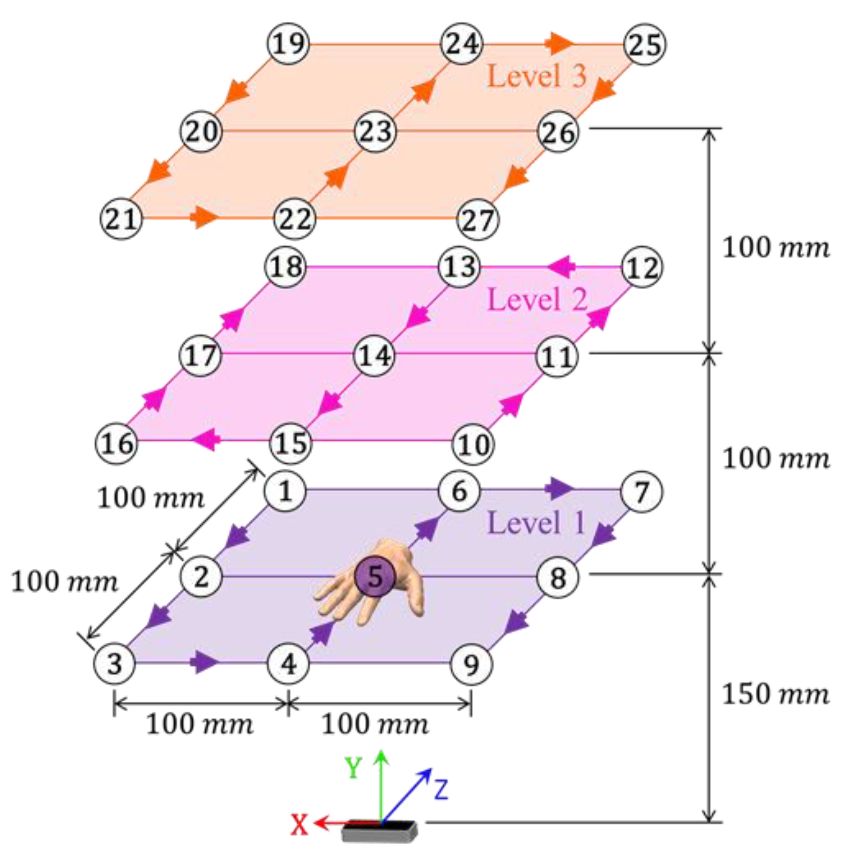
The static experiments consider twenty-seven different positions for the wooden hand, separated into three levels of height. As the experiments were performed using the two arrangements of the LMC (Figure 7), fifty-four static tests were performed in total and in each experiment 30 s of reading were collected. The positions arrangement is outlined in Figure 8. Note in Figure 8 that position number 5 is highlighted and this is due to the fact that it was chosen as the reference position used for calculating distances, due to its proximity to the sensor. Therefore, errors and repeatability of each of the twenty-six remaining positions for each LMC arrangement considered are evaluated.
4.2.2. Linear Displacement Experiments
The linear displacement experiments have the following specific objectives: observation of the sensor acquisition rate; the verification of the consistency of the readings made when there is a linear displacement; calculating the error of the distance measurements between two reading positions, one of which is considered a reference; the evaluation of repeatability in the evaluated positions; the investigation of which axes of the LMC have better quality in the position readings.
In this type of test, the hand model performs linear trajectories parallel to the orthogonal axes of the sensor. The movement starts and ends at the midpoint of each trajectory, with five equal displacement cycles being performed.
There are seven linear displacement experiments, three with a trajectory parallel to the lateral axis of the robotic arm (lateral displacement), three parallel to the frontal axis (frontal displacement), and one with vertical displacement, parallel to the Y-axis of the sensor (vertical displacement). As the experiments were performed using the two arrangements of the LMC, fourteen linear displacement tests were performed in total. In all of these experiments, the wooden hand remains oriented with the palm facing downwards, as well as in static experiments. The trajectories of each experiment in this type of test, as well as the length of each displacement are outlined in Figure 9.
As can be seen from Figure 9, the positions located at the midpoint of the trajectory has the index ‘R’ because the positions are considered as a reference for each experiment. Thus, the distances shown represent the actual displacement of the robotic arm in relation to the central position. The ‘A’ and ‘B’ indices are for differentiating positions in the presentation of results. Two positions are then evaluated for each of the seven linear displacement experiments, totaling twenty-eight positions in the two sensor arrangements.
It is important to note that the frontal linear displacements on the first level have a shorter trajectory than the other levels due to the restriction in the movement of the robotic arm.
4.3. Circular Displacement Experiments
The circular displacement experiments have the specific objectives: observation of the LMC acquisition rate; verification of the consistency of the readings made when there is displacement in more than one axis of the sensor; the calculation of the error in relation to the programmed trajectory; the evaluation of the correlation between two orthogonal axes.
Figure 10 shows the continuous circular path of 100 mm radius and without breaks used for experimental tests. There are three experiments in the two LMC arrangements, totaling six experiments.
5. Experimental Results
In order to guarantee a better reading quality in the experiments, some precautions were taken, such as reducing the interference of external light, sealing the windows so as not to be influenced by sunlight. Another precaution that was taken was to deselect some options of the sensor API regarding the automatic orientation of its axes and the robust mode, which increases the intensity of the infrared LEDs as needed. Both options can impair the experiments due to the fact that they automatically modify the reading parameters.
At the end of all collections, the mean acquisition rate in frames per second for each type of experiment and sensor arrangement was verified, as can be seen in Figure 11.
As in Figure 11 in all the experiments, the shape of the curve was a straight line, which represents a constant acquisition rate. The average rate of 113.28 fps is well above the range of 15 to 30 fps considered satisfactory for application in a game [35]. It is also noted that the calculated acquisition rate was three times that observed by [22] and almost double that observed by [24], this leads to the conclusion that the LMC SDK version 3 has been improved in this respect.
5.1. Analysis of Static Experiments for the Hand Palm
The average and maximum errors observed in the transversal arrangement static tests were 17.47 and 33.65 mm, respectively, slightly larger than in the longitudinal static tests, with 15.07 and 28.35 mm, Table 1. It is also possible to conclude, from the averages calculated at each level that the error tends to increase as the hand moves away from the sensor. The average values for repeatability in both sensor arrangements were 0.25 and 0.30 mm (transversal and longitudinal, respectively), indicating good accuracy in repeatability conditions.
The results presented in [20,23,26,27] used a version of the LMC SDK in which tool tracking is possible. Thus, its measurements were all made using a rod as a tracked element, which facilitates its measurement for geometric reasons. The analysis made in this paper was related to the palm, whose measured point is not well defined, such as in real applications of hand rehabilitation. The average errors observed in the transversal and longitudinal arrangements static tests are greater than those presented by [25] and close to those presented by [24], works in which measurements were made at the fingertips. Regarding the calculated repeatability, the mean values were lower than that observed in [22,23,24] and close to the value found by [20].
Static positioning is important in the development of serious games to allow the selection, picking, activation of objects in which the hand must be briefly in this position. Thus, if the object interaction in the serious game has appropriate dimensions, due to the sensor errors for static configurations, it will not be a problem.
5.2. Analysis of Linear Displacement Experiments for the Hand Palm
Figure 12 shown the graphs of linear displacement over time for lateral movements, with the sensor arrangements separated in two columns and the experiments organized in the three levels.
For lateral linear displacements with leap motion in the transversal arrangement, the displacement on the X-axis is notable, while on the other axes, the variation is almost imperceptible. Its waveform also corresponds to the movement made by the wooden hand, being noticeable the stretches where there was displacement and where the hand was still, Figure 12. In lateral linear displacements with leap motion in the longitudinal arrangement, the displacement on the Z-axis is evident, but the displacements do not present a constant size, showing a noticeable variation from one reference position to another, Figure 12.
In vertical movement, in both arrangements, the readings were predominantly on the Y-axis, as expected, and the waveform also corresponding to the displacement performed by the hand, Figure 13. This indicates a good quality in tracking vertical movements.
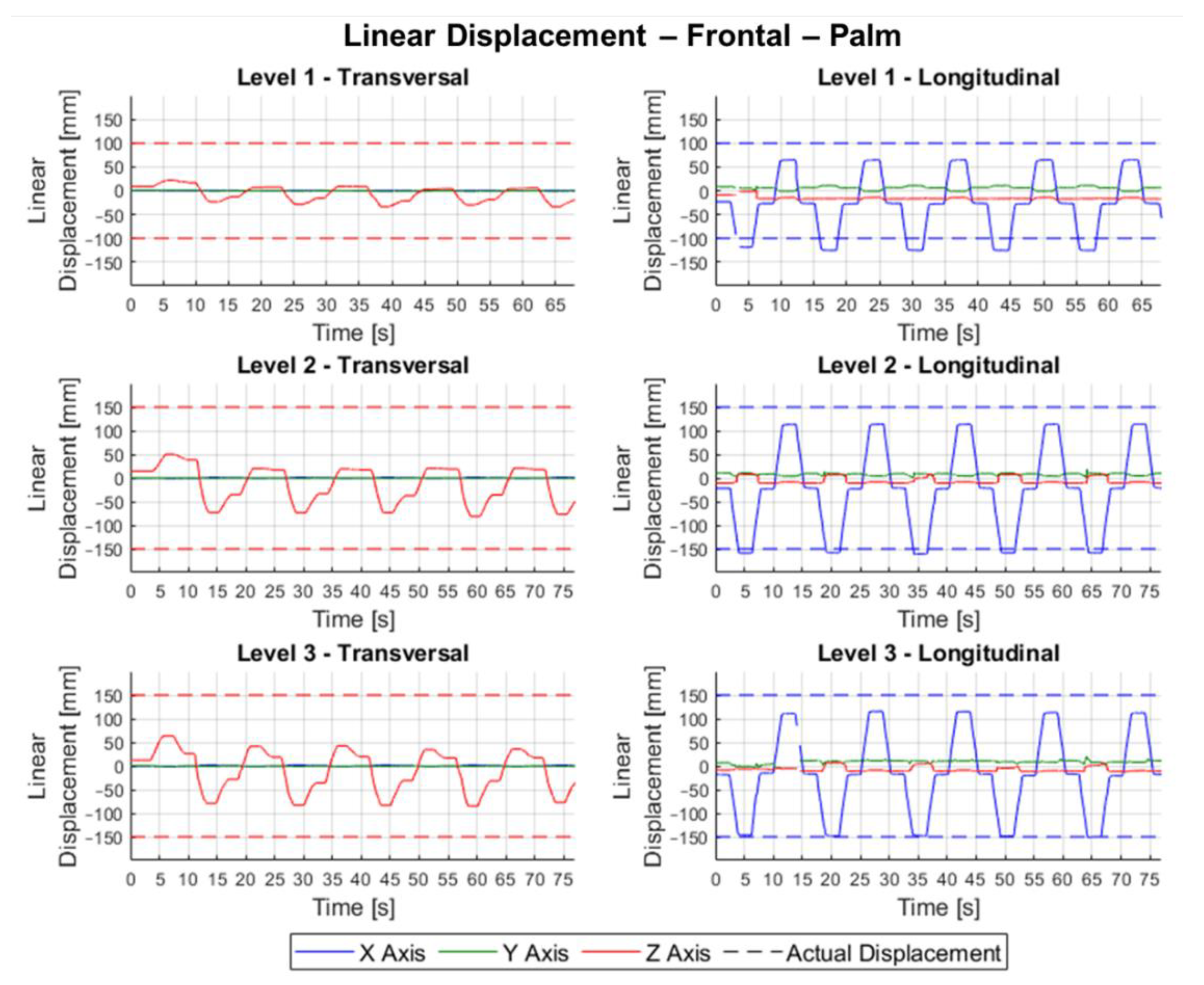
The linear displacements in the frontal movement in the transversal arrangement present curves predominantly on the Z-axis, as expected, but there is a notable variation between consecutive measurements of the reference position, Figure 14.
Table 2 shows the errors for each linear movement and depending on the sensor’s layout. In Table 2 it is possible to observe, for the case of lateral linear movements, that the longitudinal arrangement does not present reliable results for linear tracking. One explanation for this is the fact that the Z-axis has low accuracy when compared to the X-axis. The consistency of the sensor in both sensor arrangement in the vertical movement was close to 100%, which indicates good sample quality. The mean of the errors in the vertical displacements were 11.52 and 13.20 mm for the transversal and longitudinal arrangements, respectively. Another possible observation to be made is that the error in Position ‘B’ in both arrangements is greater than in Position ‘A’, which indicates better readings in positions closer to the sensor, as observed in [22].
Regarding repeatability, the vertical transversal arrangement test obtained an average of 1.04 mm, around six times less than the longitudinal of 6.19 mm. It can be seen for this type of experiment that the transversal arrangement obtained better results than the longitudinal one.
Analyzing Table 2, for frontal movement, it is noted that there was good consistency in the collection of samples, with practically 100% of the frames considered valid by the API. As observed in the lateral movements, the frontal ones also showed a greater error when the predominant axis is the Z, which can be seen in the mean (89.09 mm) and maximum (123.87 mm) values of the experiments in the transversal arrangement. In the longitudinal arrangement, whose axis X is predominant, the mean and maximum values (15.85 and 22.72 mm, respectively) were close to those observed in the lateral movements. In the repeatability of frontal linear movements, the same phenomenon observed in the error occurs, whose mean (25.24 mm) and maximum (54.96 mm) values in the transversal arrangement were higher than those of the longitudinal arrangement (8.51 and 17.96 mm, respectively).
It should be noted that both the errors and the repeatability observed in the linear displacement experiments are much greater than those observed in the dynamic experiments by [20]. It can be concluded by the linear displacement experiments that the X and Y-axes have better quality readings, when compared to the Z-axis. In this way, in the development of serious games that require more precise linear movements, these can be implemented in the X and Y-axes because the amplitude of movement of the upper limb during the linear movement will be reproduced without difficulties (as long as the game values are set higher than the error, Table 2). However, if it is necessary to use the Z-axis, it is necessary to envisage the realization of coarse movements, that is, with great amplitudes (greater than the error of 89.09 mm).
5.3. Analysis of Circular Displacement Experiments for the Hand Palm
In Figure 15a, circular trajectories are observed in the frontal plane, very close to the real trajectory in the XY plane for transversal circular displacements, while an elliptical shape in the YZ plane predominates the longitudinal arrangements. For better visualization, all graphics were translated so that the center of the circle drawn on the trajectories is located at the origin of the reference systems.
Table 3 shows the errors related to circular tests for the hand palm.
Table 3 shows that the percentage of frames valid for circular trajectories experiments in the frontal plane were close to 100%, indicating good consistency in readings. The average errors observed in the transversal arrangement were −9.00 mm, ranging from −14.13 to −6.04 mm, while in longitudinal arrangement the errors were approximately −12 mm, ranging from −49.72 to 2.52 mm.
To the lateral circular motion, the graphs referring to transversal arrangement circular movements have an elliptical shape in the YZ plane, while in the longitudinal circular movements, the shape of the trajectory approaches that of a circle, being observed in the XY plane, Figure 15b. In the planes perpendicular to hand displacement, the graphs show little variation, as expected.
Table 3 shows to lateral circular movements the percentage of valid frames was 100%, indicating very good quality in the readings. The average errors calculated in the lateral transversal circular movements were approximately −14 mm, ranging from −49.57 to −1.08 mm, and in the longitudinal arrangement errors of −7.66 mm, ranging from −11.95 to −1.34 mm. For vertical circular movements the trajectories in all experiments have an elliptical shape in the XZ plane, Figure 15c. Table 3 shows that the percentage of valid frames is 100% in all experiments, indicating good consistency in readings. The average errors observed in the vertical transversal circular movements were approximately −13 mm, ranging from −47.32 to −6.03 mm, while in the longitudinal circular movements the errors were approximately −11.5 mm, ranging from −46.20 to 2.76 mm.
In general, it can be concluded that the best correlation between axes for circular experiment was between the X and Y axes, which showed circular trajectories closer to the actual hand displacement in the tests, differently from what was observed by [23], who calculated minor errors in the XZ plane in their circular experiments. Thus, for the development of serious games the circular movements can be performed in all planes.
Based on the analysis of the experimental results, some conclusions can be drawn regarding the use of LMC in the development of a serious game applied to rehabilitation of upper limbs. At first, the sensor acquisition rate resulted suitable for the specific application. This aspect benefits from the specific features of rehabilitation task, which are handled in a closed environment, with little interference from external light. Regarding the measurements taken in the palm of the hand, the repeatability of the sensor was kept with suitable small values even in the most distant positions of the sensor and this will reflect a good tracking of the hands during the serious game if the LMC is kept in transversal arrangement. Regarding the consistency of its measurements, it can be concluded that the sensor tracked the hand properly and reliably in all tests. However, the workspace used in the experiments is small when compared to the workspace of the human upper limbs. Thus, it is necessary to carefully choose how the device will be positioned relative to the patient pose. In the linear displacement experiments, it was possible to conclude that the axis that has the greatest error in its measurements is the Z-axis, which, in the transversal arrangement, refers to the user’s frontal axis. Thus, in the development of the serious game, it will be convenient to prioritize the activities in which vertical and lateral displacements are performed. Even with the ellipsoid shape observed in the circular trajectories, the LMC was able to track the hands well, identifying the quadrant in each plane. Accordingly, the LMC can be a suitable tool to help reproducing circular and linear rehabilitation exercises. Leap motion can be used also in the progress scales such as the Motor Assessment Scale (MAS).
As future work we plan to combine the proposed LMC with other robotic structures for validating real rehabilitation tasks with patients having upper limb impairments. Furthermore, we will focus on the developments of serious games to upper limb rehabilitation by considering the above-mentioned features and limitations of the leap motion controller.
6. Conclusions
This paper addressed the feasibility of using a commercial leap motion controller (LMC) for rehabilitation tasks of human upper limbs. Careful attention has been given to the LMC’s characteristics in terms of structure, workspace, reference system, application programmer interface, and data processing. An experimental set-up and procedure have been proposed to experimentally validate the main performance in terms accuracy, repeatability, and acquisition rate. Based on the analysis of the experimental results, one can conclude that the sensor tracked the hand properly and reliably mostly in all tests. However, the workspace used in the experiments is small when compared to the workspace of the human upper limbs. Thus, it is necessary to carefully choose how the device is positioned relative to the patient pose. Moreover, in the development of the serious game, it will be convenient to prioritize the activities in which vertical and lateral displacements are performed. The LMC can be a suitable tool to help reproducing circular and linear rehabilitation exercises and it can be used also in the progress scales such as the Motor Assessment Scale (MAS). Future work will focus, in particular, on the developments of serious games to upper limb rehabilitation considering the above-mentioned features and limitations of the leap motion controller.
Author Contributions
Conceptualization, M.R.S.B.d.S. and R.S.G.; methodology, M.R.S.B.d.S. and R.S.G.; software, M.R.S.B.d.S.; validation, M.R.S.B.d.S., R.S.G. and G.C.; formal analysis, M.R.S.B.d.S., R.S.G. and G.C.; investigation, M.R.S.B.d.S., R.S.G. and G.C.; resources, M.R.S.B.d.S., R.S.G. and G.C.; data curation, M.R.S.B.d.S., R.S.G. and G.C.; writing—original draft preparation, M.R.S.B.d.S., R.S.G. and G.C.; writing—review and editing, M.R.S.B.d.S., R.S.G. and G.C.; visualization, M.R.S.B.d.S., R.S.G. and G.C.; supervision, R.S.G. and G.C.; project administration, R.S.G.; funding acquisition, R.S.G. and G.C. All authors have read and agreed to the published version of the manuscript.
Funding
This research was funded by the UFU, FAPEMIG, CNPq and CAPES (Finance Code 001).
Institutional Review Board Statement
Not applicable.
Informed Consent Statement
Not applicable.
Conflicts of Interest
The authors declare no conflict of interest. The funders had no role in the design of the study; in the collection, analyses, or interpretation of data; in the writing of the manuscript, or in the decision to publish the results.
References
- Rodgers, H.; Bosomworth, H.; Krebs, H.I.; van Wijck, F.; Howel, D.; Wilson, N.; Aird, L.; Alvarado, N.; Andole, S.; Cohen, D.; et al. Robot assisted training for the upper limb after stroke (RATULS): A multicentre randomised controlled trial. Lancet 2019, 394, 51–62. [Google Scholar] [CrossRef] [Green Version]
- Ben Hamida, I.; Laribi, M.A.; Mlika, A.; Romdhane, L.; Zeghloul, S.; Carbone, G. Multi-Objective optimal design of a cable driven parallel robot for rehabilitation tasks. Mech. Mach. Theory 2020, 156, 104141. [Google Scholar] [CrossRef]
- Major, Z.Z.; Vaida, C.; Major, K.A.; Tucan, P.; Simori, G.; Banica, A.; Brusturean, E.; Burz, A.; Craciunas, R.; Ulinici, I.; et al. The Impact of Robotic Rehabilitation on the Motor System in Neurological Diseases. A Multimodal Neurophysiological Approach. Int. J. Environ. Res. Public Health 2020, 17, 6557. [Google Scholar] [CrossRef]
- Gonçalves, R.S.; Brito, L.S.F.; Moraes, L.P.; Carbone, G.; Ceccarelli, M. A fairly simple mechatronic device for training human wrist motion. Int. J. Adv. Robot. Syst. 2020, 17, 1–15. [Google Scholar] [CrossRef]
- Gonçalves, R.S.; Rodrigues, L.A.O. Development of nonmotorized mechanisms for lower limb rehabilitation. Robotica 2021, 1, 1–18. [Google Scholar] [CrossRef]
- Barbosa, A.M.; Carvalho, J.C.M.; Gonçalves, R.S. Cable-driven lower limb rehabilitation robot. J. Braz. Soc. Mech. Sci. Eng. 2018, 40, 245. [Google Scholar] [CrossRef]
- Hatem, S.M.; Saussez, G.; Della Faille, M.; Prist, V.; Zhang, X.; Dispa, D.; Bleyenheuft, Y. Rehabilitation of Motor Function after Stroke: A Multiple Systematic Review Focused on Techniques to Stimulate Upper Extremity Recovery. Front. Hum. Neurosci. 2016, 10, 442. [Google Scholar] [CrossRef] [Green Version]
- Moraes, L.P.; Brito, L.; Gonçalves, R.S. Development of serious game for a robotic device to assist at wrist rehabilitation. In Proceedings of the 25th International Congress of Mechanical Engineering, Uberlandia, Brazil, 20–25 October 2019; pp. 1–7. [Google Scholar]
- Ferreira, B.; Lourenco, J.; Menezes, P. A Serious Game for Post-Stroke Motor Rehabilitation. In Proceedings of the 2019 5th Experiment International Conference (exp.at’19), Funchal, Portugal, 12–14 June 2019. [Google Scholar] [CrossRef]
- Cortés-Péres, I.; Zagalaz-Anula, N.; Montoro-Cárdenas, D.; Lomas-Veja, R.; Obrero-Gaitán, E.; Osuna-Pérez, M.C. Leap Motion Controller Video Game-Based Therapy for Upper Extremity Motor Recovery in Patients with Central Nervous System Diseases. A Systematic Review with Meta-Analysis. Sensors 2021, 21, 2065. [Google Scholar] [CrossRef] [PubMed]
- Fernández-González, P.; Tejada, M.C.; Monge-Pereira, E.; Collado-Vázquez, S.; Baeza, P.S.-H.; Cuesta-Gómez, A.; Simbaña, E.D.O.; Huete, A.J.; Molina-Rueda, F.; De Quirós, C.B.-B.; et al. Leap motion controlled video game-based therapy for upper limb rehabilitation in patients with Parkinson’s disease: A feasibility study. J. Neuroeng. Rehabil. 2019, 16, 133. [Google Scholar] [CrossRef] [PubMed]
- Oña, E.D.; Balaguer, C.; La Cuerda, R.C.-D.; Collado-Vázquez, S.; Jardón, A. Effectiveness of Serious Games for Leap Motion on the Functionality of the Upper Limb in Parkinson’s Disease: A Feasibility Study. Comput. Intell. Neurosci. 2018, 2018, 1–17. [Google Scholar] [CrossRef]
- Aguilar-Lazcano, C.A.; Rechy-Ramirez, E.J. Performance analysis of Leap motion controller for finger rehabilitation using serious games in two lighting environments. Measurement 2020, 157, 107677. [Google Scholar] [CrossRef]
- Tarakci, E.; Arman, S.N.; Tarakci, D.; Kasapcopur, O. Leap Motion Controller–based training for upper extremity rehabilitation in children and adolescents with physical disabilities: A randomized controlled trial. J. Hand Ther. 2020, 33, 220–228.e1. [Google Scholar] [CrossRef]
- Dawes, F.; Penders, J.; Carbone, G. Remote Control of a Robotic Hand Using a Leap Sensor. In Advances in Mechanism and Machine Science; Springer: Cham, Switzerland, 2019; Volume 68, pp. 332–341. [Google Scholar] [CrossRef]
- Guzsvinecz, T.; Szucs, V.; Sik-Lanyi, C. Suitability of the Kinect Sensor and Leap Motion Controller—A Literature Review. Sensors 2019, 19, 1072. [Google Scholar] [CrossRef] [Green Version]
- Hantrakul, L.; Kaczmarek, K. Implementations of the Leap Motion in sound synthesis, effects modulation and assistive performance tools. In Proceedings of the ICMC|SMC, Athens, Greece, 14–20 September 2014; pp. 648–653. [Google Scholar]
- Wozniak, P.; Vauderwange, O.; Mandal, A.; Javahiraly, N.; Curticapean, D. Possible applications of the LEAP motion controller for more interactive simulated experiments in augmented or virtual reality. In Proceedings of the SPIE 9946, Optics Education and Outreach IV, San Diego, CA, USA, 27 September 2016. [Google Scholar] [CrossRef]
- Khelil, B.; Amiri, H. Hand Gesture Recognition Using Leap Motion Controller for Recognition of Arabic Sign Language. In Proceedings of the 3rd International Conference on Automation, Control, Engineering and Computer Science, Hammamet, Tunisia, 20–22 March 2016; pp. 233–238. [Google Scholar]
- Weichert, F.; Bachmann, D.; Rudak, B.; Fisseler, D. Analysis of the Accuracy and Robustness of the Leap Motion Controller. Sensors 2013, 13, 6380–6393. [Google Scholar] [CrossRef] [PubMed] [Green Version]
- Manipulating Industrial Robots—Performance Criteria and Related Test Methods. In ISO 9283; International Organization for Standardization: Geneva, Switzerland, 1998.
- Guna, J.; Jakus, G.; Pogačnik, M.; Tomažič, S.; Sodnik, J. An Analysis of the Precision and Reliability of the Leap Motion Sensor and Its Suitability for Static and Dynamic Tracking. Sensors 2014, 14, 3702–3720. [Google Scholar] [CrossRef] [Green Version]
- Hernoux, F.; Béarée, R.; Gibaru, O. Investigation of dynamic 3D hand motion reproduction by a robot using a Leap Motion. In Proceedings of the 2015 Virtual Reality International Conference, Laval, France, 8–10 April 2015; p. 24. [Google Scholar] [CrossRef]
- Tung, J.Y.; Lulic, T.; Gonzalez, D.A.; Tran, J.; Dickerson, C.; Roy, E.A. Evaluation of a portable markerless finger position capture device: Accuracy of the Leap Motion controller in healthy adults. Physiol. Meas. 2015, 36, 1025–1035. [Google Scholar] [CrossRef]
- Valentini, P.P.; Pezzuti, E. Accuracy in fingertip tracking using Leap Motion Controller for interactive virtual applications. Int. J. Interact. Des. Manuf. 2017, 11, 641–650. [Google Scholar] [CrossRef]
- Curiel-Razo, Y.-I.; Hernandez, O.I.; Sepúlveda-Cervantes, G.; Hurtado-Ramos, J.B.; González-Barbosa, J.-J. Leap motion controller three dimensional verification and polynomial correction. Measurement 2016, 93, 258–264. [Google Scholar] [CrossRef]
- Placidi, G.; Cinque, L.; Polsinelli, M.; Spezialetti, M. Measurements by A LEAP-Based Virtual Glove for the Hand Rehabilitation. Sensors 2018, 18, 834. [Google Scholar] [CrossRef] [Green Version]
- Shah, V.; Cuen, M.; McDaniel, T.; Tadayon, R. A Rhythm-Based Serious Game for Fine Motor Rehabilitation Using Leap Motion. In Proceedings of the 2019 58th Annual Conference of the Society of Instrument and Control Engineers of Japan (SICE), Hiroshima, Japan, 10–13 September 2019; pp. 737–742. [Google Scholar] [CrossRef]
- Souza, J.T.; Naves, E.L.M.; de Sá, A.A.R. Computer vision devices for tracking gross upper limb movements in post-stroke rehabilitation. Res. Soc. Dev. 2021, 10, e57910616143. [Google Scholar] [CrossRef]
- Aguilera-Rubio, Á.; Alguacil-Diego, I.M.; Mallo-López, A.; Cuesta-Gómez, A. Use of the Leap Motion Controller® System in the Rehabilitation of the Upper Limb in Stroke. A Systematic Review. J. Stroke Cereb. Dis. 2021, 31, 106174. [Google Scholar] [CrossRef] [PubMed]
- Kapandji, A.I. Upper Limb. In The Physiology of the Joints, 6th ed.; Churchill Livingstone: London, UK, 2007; Volume 1. [Google Scholar]
- Duncan, P.W.; Propst, M.; Nelson, S.G. Reliability of the Fugl-Meyer assement of sensoriomotor recovery following cerebrovascular accident. Phys Ther. 1983, 63, 1606–1610. [Google Scholar] [CrossRef] [PubMed]
- Poole, J.L.; Whitney, S.L. Motor assessment scale for stroke patients: Concurrent validity and interrater reliability. Arch. Phys. Med. Rehabil. 1988, 69, 195–197. [Google Scholar]
- Perry, J. MatLeap: MATLAB Interface to the Leap Motion Controller. Github. 2014. Available online: https://github.com/jeffsp/matleap/tree/afb3f57f94095f82841671f50dd7f3344ec6590d (accessed on 28 October 2021).
- Peñaherrera-Pulla, O.; Baena, C.; Fortes, S.; Baena, E.; Barco, R. Measuring Key Quality Indicators in Cloud Gaming: Framework and Assessment Over Wireless Networks. Sensors 2021, 21, 1387. [Google Scholar] [CrossRef] [PubMed]
Figure 1.
Workspace of a leap motion controller in a Cartesian reference frame (Adapted from [18]).
Figure 1.
Workspace of a leap motion controller in a Cartesian reference frame (Adapted from [18]).

Figure 2.
Entities belonging to the hand class (Adapted from [19]).
Figure 2.
Entities belonging to the hand class (Adapted from [19]).

Figure 3.
Main movements of the upper limb, except fingers movements.

Figure 4.
(a) Experimental apparatus. (b) Cartesian axes of the robotic arm and workspace used in the experiments.
Figure 4.
(a) Experimental apparatus. (b) Cartesian axes of the robotic arm and workspace used in the experiments.

Figure 5.
(a) Representation of the mean vectors of the position of the reference point () and of the reading position n () and; (b) representation of the average vector, relative to the reference, of the reading position (), the known displacement () e and its measurement error ().
Figure 5.
(a) Representation of the mean vectors of the position of the reference point () and of the reading position n () and; (b) representation of the average vector, relative to the reference, of the reading position (), the known displacement () e and its measurement error ().

Figure 6.
Representation of the repeatability of the measurement of position n.

Figure 7.
LMC arrangement used in the experiments: (a) transversal and (b) longitudinal.

Figure 8.
Reading positions for static experiments.

Figure 9.
Linear displacement experiments: (a) lateral; (b) frontal and (c) vertical.

Figure 10.
Circular displacement experiments on the (a) lateral, (b) vertical and (c) front axes.

Figure 11.
Mean acquisition rates. (a) Static experimental tests; (b) linear experimental tests; (c) circular experimental tests.
Figure 11.
Mean acquisition rates. (a) Static experimental tests; (b) linear experimental tests; (c) circular experimental tests.

Figure 12.
Linear displacement of the palm in the lateral plane.

Figure 13.
Linear displacements of the palm to the vertical movement.

Figure 14.
Linear displacement relative positions of the palm in frontal movement.

Figure 15.
Relative palm positions to circular trajectory test. (a) Frontal; (b) lateral; (c) vertical axes.
Figure 15.
Relative palm positions to circular trajectory test. (a) Frontal; (b) lateral; (c) vertical axes.


Table 1.
Results of static tests for the hand palm.
| Transversal Arrangement | |||
|---|---|---|---|
| Level | |||
| 1 | 9.38 | 0.19 | 100.00 |
| 2 | 14.91 | 0.37 | 100.00 |
| 3 | 27.24 | 0.18 | 100.00 |
| Mean | 17.47 | 0.25 | 100.00 |
| Max. | 33.65 | 2.18 | - |
| Longitudinal arrangement | |||
| Level | |||
| 1 | 12.65 | 0.36 | 100.00 |
| 2 | 11.37 | 0.32 | 100.00 |
| 3 | 20.93 | 0.23 | 99.83 |
| Mean | 15.07 | 0.30 | 99.94 |
| Max. | 28.35 | 1.26 | - |
Table 2.
Results of consolidated linear displacements for the palm.
| Transversal Arrangement | Longitudinal Arrangement | |||||
|---|---|---|---|---|---|---|
| Axis | ||||||
| Lateral | 12.39 | 1.59 | 100.00 | 114.71 | 21.71 | 100.00 |
| Vertical | 11.52 | 1.04 | 99.21 | 13.20 | 6.19 | 99.25 |
| Frontal | 89.09 | 25.24 | 100.00 | 15.85 | 8.51 | 99.54 |
| Max. | 123.87 | 54.96 | − | 121.59 | 52.64 | − |
Table 3.
Results of circular movements of palm hand.
| Transversal Arrangement | ||||
|---|---|---|---|---|
| Hand | ||||
| Frontal | −9.00 | −14.13 | −6.04 | 100.00 |
| Lateral | −13.35 | −49.57 | −1.08 | 100.00 |
| Vertical | −13.05 | −47.32 | −6.03 | 100.00 |
| Longitudinal Arrangement | ||||
| Hand | ||||
| Frontal | −11.99 | −49.72 | 2.52 | 97.49 |
| Lateral | −7.66 | −11.95 | −1.34 | 100.00 |
| Vertical | −11.47 | −46.20 | 2.76 | 100.00 |
Publisher’s Note: MDPI stays neutral with regard to jurisdictional claims in published maps and institutional affiliations. |
© 2021 by the authors. Licensee MDPI, Basel, Switzerland. This article is an open access article distributed under the terms and conditions of the Creative Commons Attribution (CC BY) license (https://creativecommons.org/licenses/by/4.0/).
Share and Cite
MDPI and ACS Style
de Souza, M.R.S.B.; Gonçalves, R.S.; Carbone, G. Feasibility and Performance Validation of a Leap Motion Controller for Upper Limb Rehabilitation. Robotics 2021, 10, 130. https://doi.org/10.3390/robotics10040130
AMA Style
de Souza MRSB, Gonçalves RS, Carbone G. Feasibility and Performance Validation of a Leap Motion Controller for Upper Limb Rehabilitation. Robotics. 2021; 10(4):130. https://doi.org/10.3390/robotics10040130
Chicago/Turabian Stylede Souza, Marcus R. S. B., Rogério S. Gonçalves, and Giuseppe Carbone. 2021. "Feasibility and Performance Validation of a Leap Motion Controller for Upper Limb Rehabilitation" Robotics 10, no. 4: 130. https://doi.org/10.3390/robotics10040130
Note that from the first issue of 2016, this journal uses article numbers instead of page numbers. See further details here.