Article

Use of Three-Level Power Converters in Wind-Driven Permanent-Magnet Synchronous Generators with Unbalanced Loads

Department of Electrical Engineering, Ming Chi University of Technology, 84 Gungjuan Road, Taishan District, New Taipei City 24301, Taiwan
Electronics 2015, 4(2), 339-358; https://doi.org/10.3390/electronics4020339
Submission received: 25 April 2015 / Accepted: 9 June 2015 / Published: 15 June 2015
(This article belongs to the Special Issue Multi-Level Converters)

Abstract

:
This paper describes the design and implementation of three-level power converters for wind-driven permanent-magnet synchronous generators with unbalanced loads. To increase voltage stress and reduce current harmonics in the electrical power generated by a wind generator, a three-phase, three-level rectifier is used. Because a synchronous rotating frame is used on the AC-input side, the use of a neutral-point-clamped controller is proposed to increase the power factor to unity and reduce current harmonics. Furthermore, a novel six-leg inverter is proposed for transferring energy from the DC voltage to a three-phase, four-wire AC source with a constant voltage and a constant frequency. The power converters also contain output transformers and filters for power buffering and filtering, respectively. All three output phase voltages are fed back to control the inverter output during load variations. A digital signal processor is used as the core control device for implementing a 1.5 kV, 75 kW drive system. Experimental data show that the power factor is successfully increased to unity and the total current harmonic distortion is 3.2% on the AC-input side. The entire system can attain an efficiency of 91%, and the voltage error between the upper and lower capacitors is approximately zero. Experimental results that confirm the high performance of the proposed system are presented.

1. Introduction

Wind energy is a type of clean and renewable energy, unlike fossil fuel energy. Wind is a nonpolluting and renewable source of energy that is referred to as “white coal in the sky”, and it is expected to play a crucial role in providing a sustainable power supply without harming the environment [1]. Basically, wind turbine design concepts can be categorized into four types according to the method adopted in their design: types A, B, C, and D [1,2,3,4]. A type A configuration involves a fixed-speed controlled wind turbine with a squirrel cage induction generator (SCIG) directly connected to the grid through a transformer. The SCIG always draws reactive power from the grid so this concept uses a capacitor bank for reactive power compensation. Type B involves a limited variable-speed controlled wind turbine with an opti-slip induction generator (OSIG) and pitch control. By varying the rotor resistance connected in series externally, the slip and output power are controlled to make the dynamic speed range 0%–10% above synchronous speed, typically. Both types A and B require starting equipment. Type C is a variable-speed controlled wind turbine with a doubly fed induction generator (DFIG) and pitch control. The stator is directly connected to the grid, while the rotor is connected through a power converter that is typically only 25%–30% of the generator rated power. The variable speed range is +/−30% around the synchronous speed. However, an induction generator is uneconomical because of its low efficiency and the requirement of auxiliary starting equipment [2]. Because of the apparent benefits of using permanent magnets for supplying flux in synchronous machines, such as the absence of excitation loss in the rotor, the use of permanent-magnet synchronous generators (PMSGs) for wind power generation has increased in recent years [5,6,7]. Type D is a full variable-speed, pitch-controlled wind turbine with the generator connected to the grid through a full-scale power converter that performs reactive power compensation and smooth grid connection over the entire speed range. The generator can be excited electrically using PMSG or SCIG that has full control of the speed range from 0% to 100% of the synchronous speed, but higher power loss in the power converter compared to type C. The proposed direct-drive, variable-speed wind energy conversion system (WECS) has the following salient features compared with SCIG and DFIG wind power systems.
(1)
Elimination of the gearbox between wind turbine and generator reduces maintenance;
(2)
Mechanical speed of the generator is controlled to capture higher wind energy;
(3)
The configuration translates into significant optimization of size, volume, and form-factor; and
(4)
The power converter acts as a buffer between the grid and generator, and thus minimizes undesirable dynamic interactions between subsystems.
Generally, wind power generation is unsustainable and unstable in natural environments. Therefore, power converters are used in wind generators to provide a constant output. The high capacity of a wind turbine indicates that the corresponding generator and power converter must operate at higher voltage levels to achieve maximum efficiency and optimum size, volume, and form-factor [8,9]. The output voltages of wind generators are excessively high for using insulated gate bipolar transistor (IGBT)-based converters. High-power PMSGs (75 kW) are characterized by low equivalent resistance and inductance, which makes it difficult to use a rectifier [10,11,12,13,14]. In practice, stand-alone operation of WECS requires constant electric quantities such as the amplitude, phase and frequency from the generator output. This necessitates the development of an electrical power converter to maintain the required electrical quality to be independent of the variations of wind speed and load. In recent years, several multilevel inverters have appeared in the literature [10,11,12,13]. Multilevel technologies have advantages such as providing an improved output waveform with smaller filter size and lower electro-magnetic interference, etc. Among them, various multilevel switching techniques have been investigated and discussed with their respective characteristics [14]. However, regardless of the switching method chosen, the gate signals to control a particular inverter system must be derived. In general, neutral point clamped pulse-width modulation (PWM) three-phase inverter which uses four switching states in each arm has the three-level voltage waveforms. That results in considerable suppression of the harmonic currents comparing with the conventional full-bridge type PWM inverters [15]. A three-phase, three-leg inverter consisting of six IGBTs is used to convert a DC source to an AC source with a balanced output. The three-phase, three-leg inverter cannot be used for three-phase, four-wire, unbalanced loads because the zero-sequence current cannot be controlled [15,16]. Moreover, the high switching frequency of IGBTs introduces voltage ripples in the output of the inverter. In this paper, a three-phase, six-leg inverter that can be used in a three-phase, four-wire AC source for providing a constant voltage, constant frequency output is proposed. Sinusoidal pulse width modulation (PWM) involving unipolar voltage switching is adopted to double the switching frequency.
The configuration of the proposed power converter (Figure 1) consists of three parts: a wind generator, a power converter, and a controller. As mentioned, the power converter comprises a three-phase, three-level rectifier, two DC-link capacitors, a three-phase, six-leg inverter, and transformers. The proposed system can transform mechanical energy into electrical energy with high power quality. In addition, the resistors connected to the output of the inverter are loads. The controller includes voltage and current sensors and a digital signal processor (DSP, R5F5630EDDFP). An encoder counter, a 12-bit analog-to-digital converter, and a PWM module are constructed in the control board of the DSP to reduce the hardware complexity and improve the reliability and maintainability of the system. Experimental results are presented to demonstrate the high performance of the proposed power converter system.
Figure 1. Block diagram of the proposed system.
Electronics 04 00339 g001

2. Principles of Operation

The proposed three-level power converter for wind-driven PMSGs is depicted in Figure 1. Let v x , v y , and v z represent the output voltages of the inverter. For simplicity, the reference frame transformation method was used for calculating reference currents and describing the control scheme.

2.1. Mathematical Model of PMSG

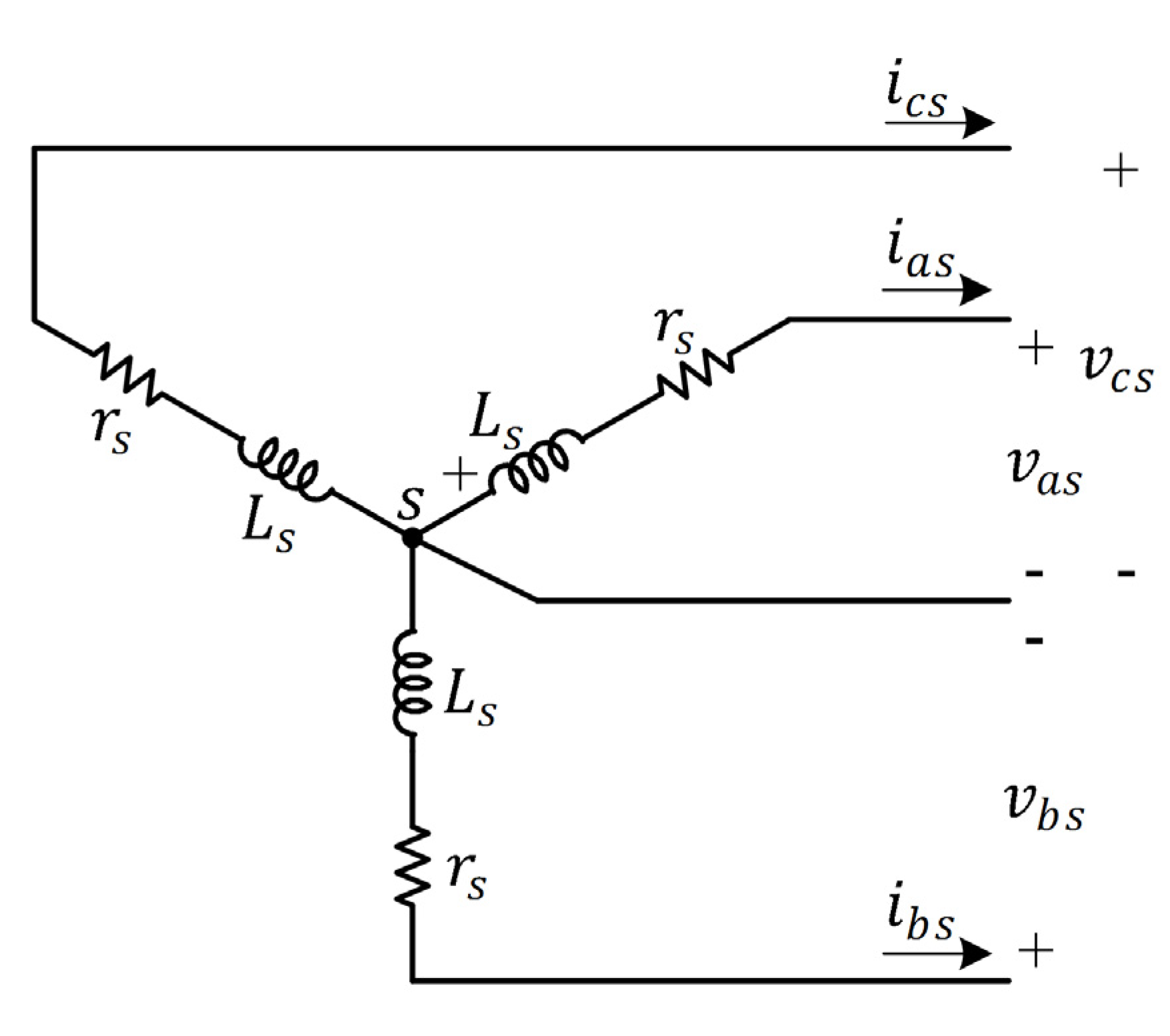
The equivalent circuit of a PMSG is shown in Figure 2. The voltage equation can be written as [6,8]
v a b c s = r s ˜ i a b c s + d d t λ a b c s
where
r s ˜ = d i a g [ r s r s r s ]
v a b c s = [ v a s v b s v c s ] T
i a b c s = [ i a s i b s i c s ] T
λ a b c s = [ λ a s λ b s λ c s ] T
Here, v a s , v b s , and v c s denote the phase voltages of the generator, and i a s , i b s , and i c s denote the line currents of the generator; furthermore, r s represents the equivalent resistance of the stator, and λ a s , λ b s , λ c s are the flux linkages of the stator. Assume that the flux harmonics of the rotor and stator are negligible. Consequently, the fluxes of the rotor and stator are sinusoidally distributed. Therefore, the flux linkage can be expressed as
λ a b c s = L s ˜ i a b c s + λ m ' ˜
where
L s ˜ = [ L l s + L m s 1 2 L m s 1 2 L m s 1 2 L m s L l s + L m s 1 2 L m s 1 2 L m s 1 2 L m s L l s + L m s ]
λ m ' ˜ = λ m ' [ sin θ r sin ( θ r 2 π 3 ) sin ( θ r + 2 π 3 ) ]
Here, θ r = ω r d t and L m s = N s 2 m ; θ r is the rotor flux angle, ω r is the rotor speed, N s is the equivalent number of turns in the stator winding, L l s is the leakage inductance of the stator winding, m is the equivalent reluctance of the stator, and λ m ' is the equivalent flux linkage of the rotor relative to the stator. According to Equations (1)–(8), the phase voltage of the generator can be obtained as
v a b c s = r s ˜ i a b c s L s ˜ d d t i a b c s + e a b c s
where e a b c s denotes the internal voltage of the generator and is proportional to ω r . In other words,
[ e a s e b s e c s ] = ω r λ m ' [ cos θ r cos ( θ r 2 π 3 ) cos ( θ r + 2 π 3 ) ]
The equation for the output power of the generator is
P e = e a s i a s + e b s i b s + e c s i c s
According to Equations (10) and (11), the output power equation can be rewritten as
P e = ω r λ m ' [ i a s cos θ r + i b s cos ( θ r 2 π 3 ) + i c s cos ( θ r + 2 π 3 ) ]
This equation shows that the output power of the generator is proportional to the rotor speed and the peak value of the three-phase currents, implying that the output power of the generator can be controlled by varying the peak value of the currents. This principle was used in this study to implement a current controller for the three-phase, three-level rectifier.
Figure 2. Equivalent circuit of a Y-connection PMSG.
Electronics 04 00339 g002

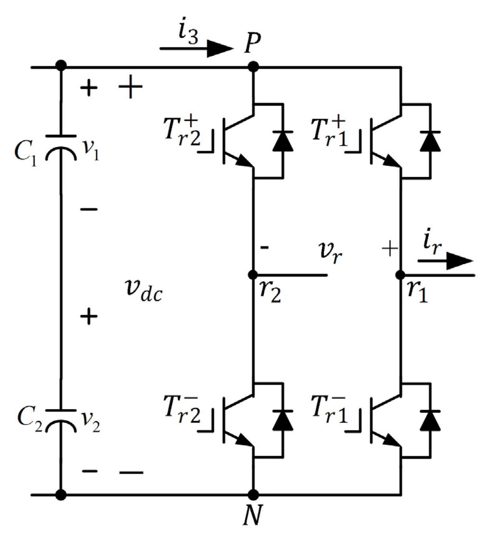
2.2. Three-Phase, Three-Level Rectifier

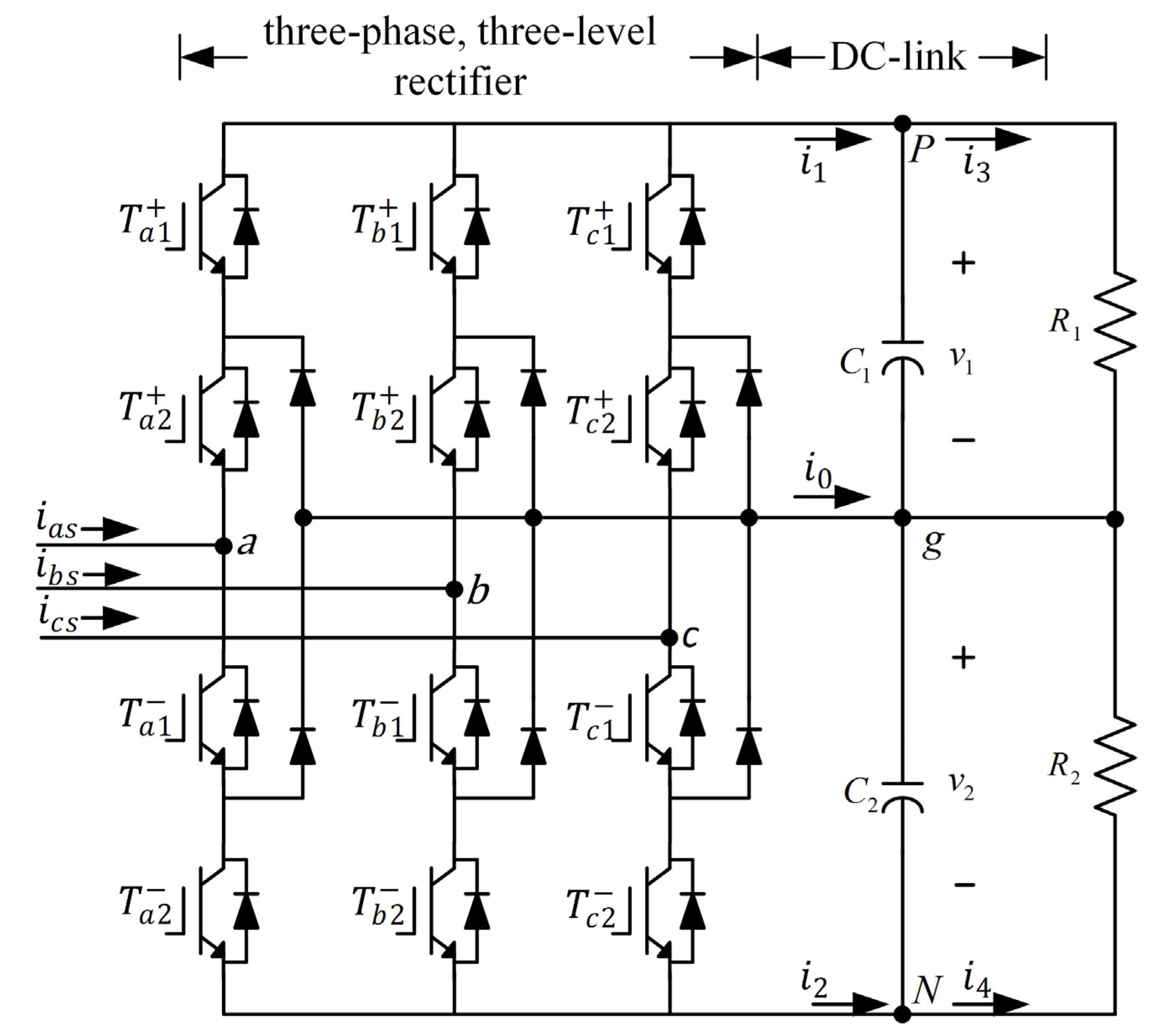
A schematic of the three-phase, three-level rectifier is shown in Figure 3. It was constructed by adding six clamping diodes with the six power switches to the conventional bridge structure. These six switches can be appropriately controlled for obtaining three levels of the DC supply voltage across the DC-link capacitors [11]. In Figure 3, the voltages of C 1 and C 2 are v 1 and v 2 , respectively. The three voltage levels of the three-phase, three-level rectifier defined by two mutually exclusive switching states—( T x 1 + , T x 1 ) and ( T x 2 + , T x 2 )—are listed in Table 1, where x denotes a, b, or c. The sinusoidal PWM is used to generate gating signals for the power switches [12].
Figure 3. Schematic of a three-phase, three-level rectifier.
Electronics 04 00339 g003
Table 1. Phase voltages of the three-phase, three-level rectifier.
Output v x g Switching State
T x 1 + T x 2 + T x 1 T x 2
v 1 1100
00110
v 2 0011
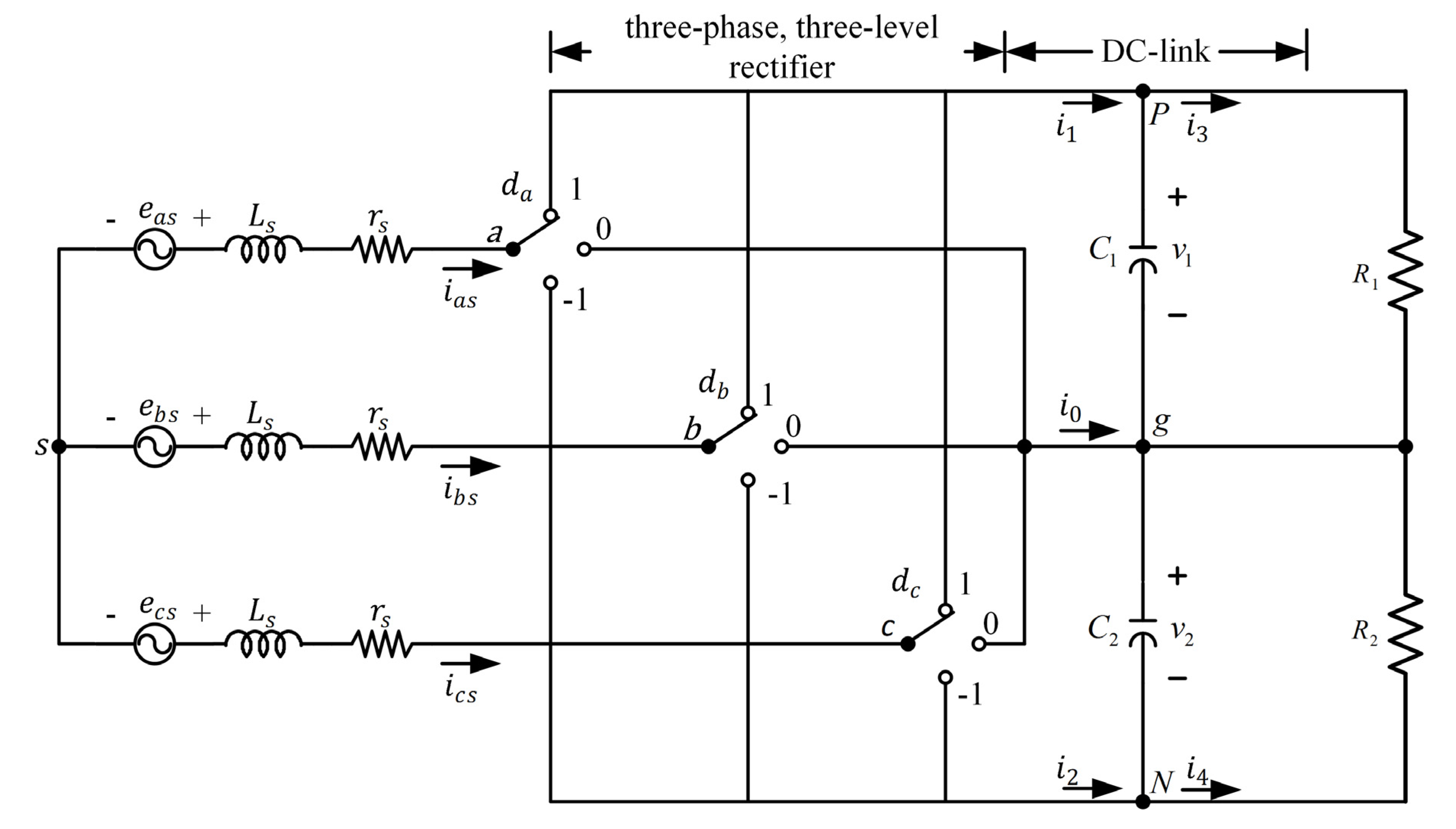
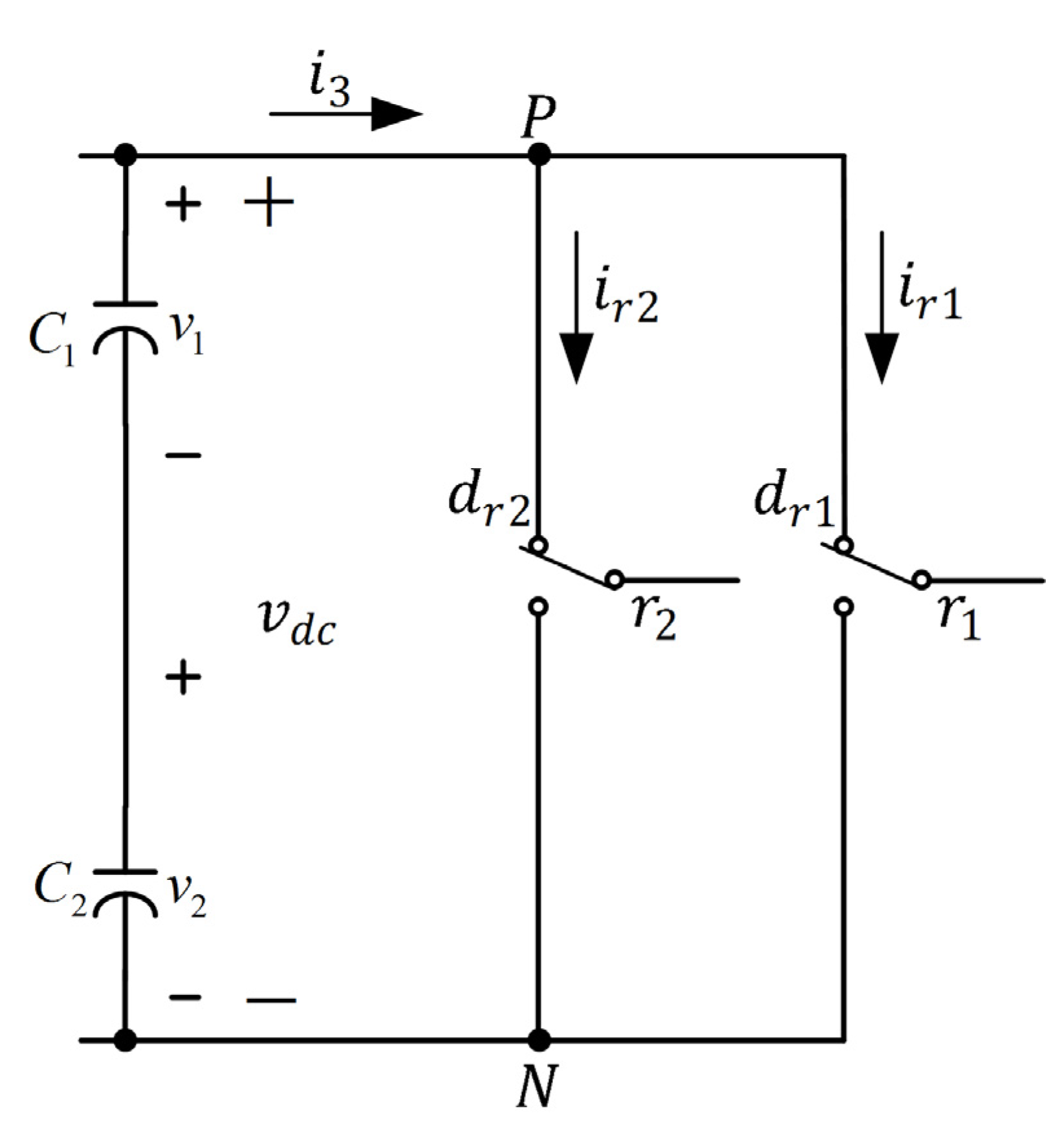
Assume that the power switches are ideal. The equivalent circuit of Figure 3 is shown in Figure 4. The following situations are illustrated:
d x = { 1 T x 1 + ,   T x 2 + : O N T x 1 ,   T x 2 : O F F 0 T x 1 ,   T x 2 + : O N T x 1 + ,   T x 2 : O F F 1 T x 1 ,   T x 2 : O N T x 1 + ,   T x 2 + : O F F
where x = a ,   b ,   c . The switching of the phase voltage v x g can be expressed as
v x g = { v 1 i f d x =   1 0 i f d x =   0 v 2 i f d x = 1
Because the three-phase voltages from the wind generator are balanced, the following expression holds:
v a b c s = [ v a s v b s v c s ] = 1 3 [ 2 1 1 1 2 1 1 1 2 ] [ v a g v b g v c g ]
where v a s , v b s , and v c s are the phase voltages relative to the neutral point of the wind generator. In Figure 4, currents i 1 and i 2 are given by
i 1 = k a 1 i a s + k b 1 i b s + k c 1 i c s
i 2 = k a 2 i a s + k b 2 i b s + k c 2 i c s
Furthermore, the current i 0 at point g is
i 0 = k a 0 i a s + k b 0 i b s + k c 0 i c s
where k x 1 , k x 2 , and k x 0 are determined as
k x n = { 1 d x = 1   0 d x = 0 ,   1
Here, x = a ,   b ,  or  c and n = 0 ,   1 ,  or  2 .
In Figure 4, the differential equations of the voltages of the upper and lower capacitors are
C 1 d d t v 1 = i 1 i 3
C 2 d d t v 2 = ( i 2 i 4 )
and the voltage error between the upper and the lower capacitors is
Δ E = v 1 v 2
where C 1 and C 2 are upper and lower DC-link capacitors, respectively. Equation (22) indicates that the voltage error of the upper and lower capacitors can be controlled by varying duty cycles of k x n , and this principle was used in this study to implement a voltage controller for the three-phase, three-level rectifier [13].
Figure 4. Equivalent circuit of the three-phase, three-level rectifier.
Electronics 04 00339 g004
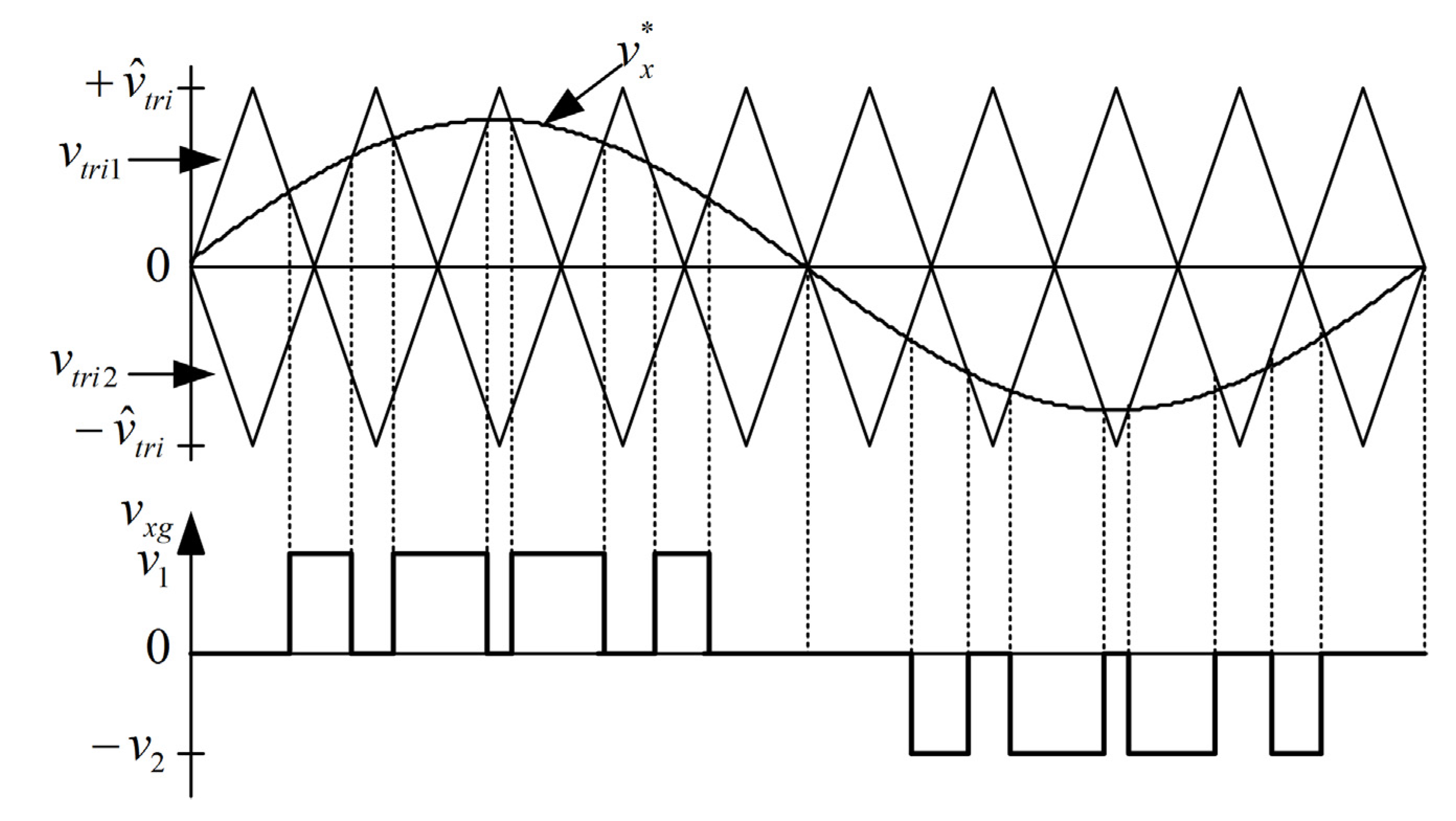
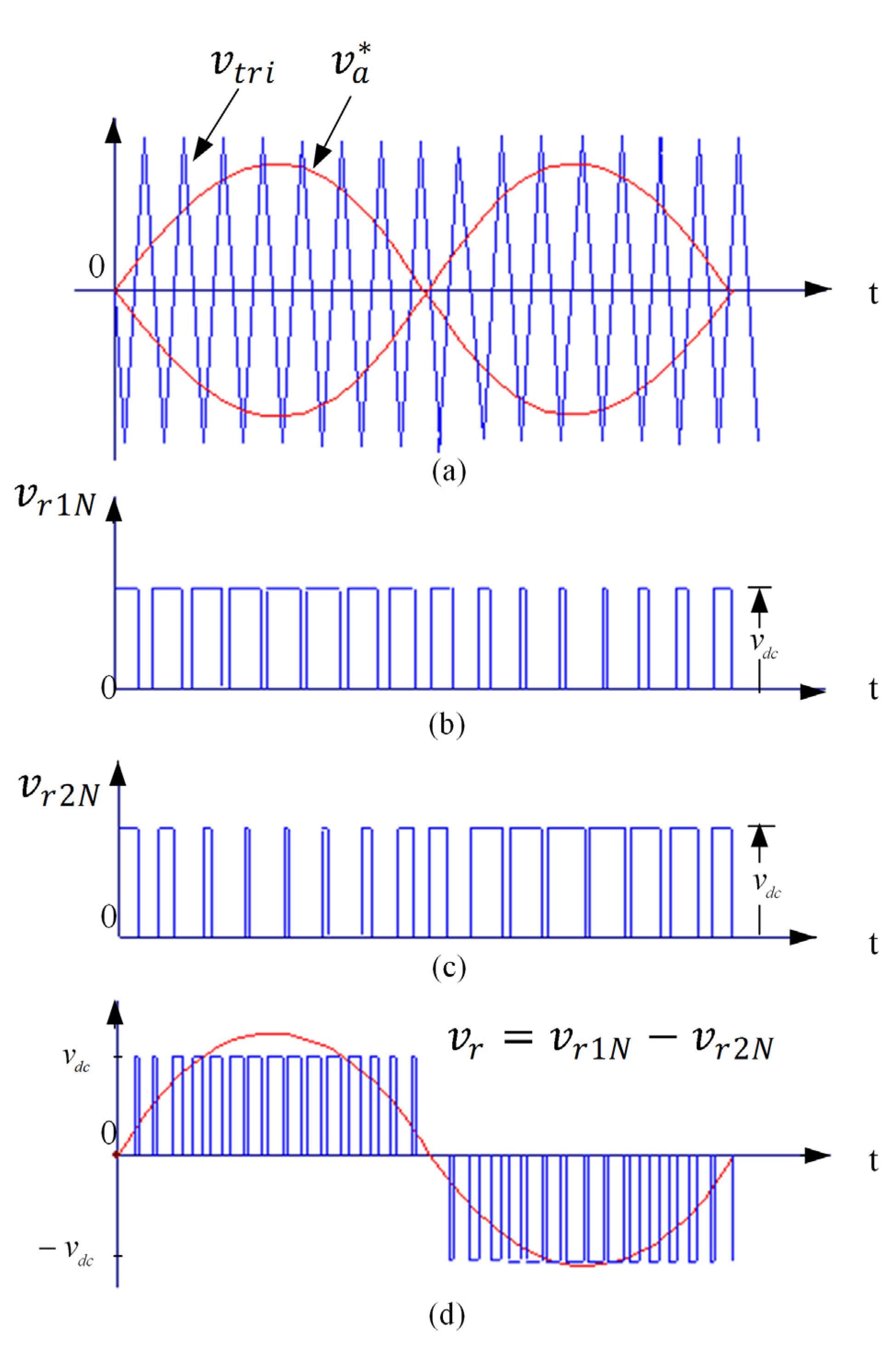
To control the three-phase, three-level rectifier, a sinusoidal PWM technique involving two carrier waves was used [14]. Gating signals for the power transistors were generated by comparing the commanding signal magnitude of v x * with the magnitude of two inverse carrier waves having the same peak-to-peak amplitude, frequency, and phase, as shown in Figure 5. The rectifier is illustrated by the following three modes of operation:
(1)
when v x * > v t r i 1 and v x * > v t r i 2 , v x g = v 1
(2)
when v t r i 1 > v x * > v t r i 2 , v x g = 0
(3)
when v x * < v t r i 1 and v x * < v t r i 2 , v x g = v 2
where x = a ,   b ,   c .
Figure 5. Sinusoidal PWM with two carrier waves.
Electronics 04 00339 g005
Figure 5 shows that the peak values of v t r i 1 and v t r i 2 are + v ^ t r i and − v ^ t r i , respectively. Therefore, there are three switching modes according to the level of the commanding signal. If the commanding signal can be produced using only half of the DC-link voltage, for example, v 1 , the magnitude of the carrier waves is compared with the commanding signal magnitude, thereby yielding the first mode of operation. If the commanding signal magnitude lies between the signal magnitudes of two carrier waves, the second mode of operation, in which the switching pattern is produced by comparing the carrier waves with the commanding signal magnitude, is conducted. Gating signals for power transistors in the third mode of operation can be obtained by comparing the magnitude of the carrier waves with the magnitude of v x * . Finally, Figure 6 shows the gating signals for the three modes of operation, illustrating that the switching pattern of the three-phase, three-level rectifier is generated by the aforementioned three modes of operation. The switching loss can be reduced by reducing the switching frequency or by reducing the instantaneous current or voltage during the switching period.
Figure 6. Switching pattern of the three-phase, three-level rectifier.
Electronics 04 00339 g006

2.3. Neutral-Point-Clamped Controller

The three-phase, three-level rectifier is implemented using switch-mode devices, and three-phase voltages are obtained from the wind generator. The statuses of the upper and lower switches are mutually exclusive, and the DC-link voltage is not shorted in normal operation. Assume that the power transistors are ideal and that the currents i a , i b , and i c are continuous. When the load varies, the voltage of the upper capacitor is lower than that of the lower capacitor; in other words, the current passing through the upper capacitor is lower than that passing through the lower capacitor. Therefore, the command voltage for the DC-link can be regulated by varying the voltage error between the upper and the lower capacitors [14]. According to Equations (16) and (19), v 1 can be increased by regulating the turn-on time for k x 1 = 1 so that i 1 increases, and vice versa. The voltage error command is
Δ E * = v 1 * v 2 *
where v 1 * and v 2 * are the voltage commands of the upper and lower capacitors and their values are half that of the DC-link voltage; in other words, v 1 * = v 2 * = v d c * 2 . If Δ E * is zero, the voltages across the DC-link capacitors are symmetrical. According to Equation (23), the compensation voltage for the DC link is
v o * = G Δ E ( Δ E )
where G Δ E is the gain of the proportional-integral voltage controller, and v o * is the voltage command of the DC-link capacitor voltage; the symbol “ ” denotes proportional-integral operation. Specifically, Equation (24) shows that v o * can be obtained by achieving proportional-integral control of the DC-link voltage error. A control block diagram of the neutral-point-clamped controller is shown in Figure 7.
Figure 7. Control block diagram of the three-phase, three-level rectifier.
Electronics 04 00339 g007

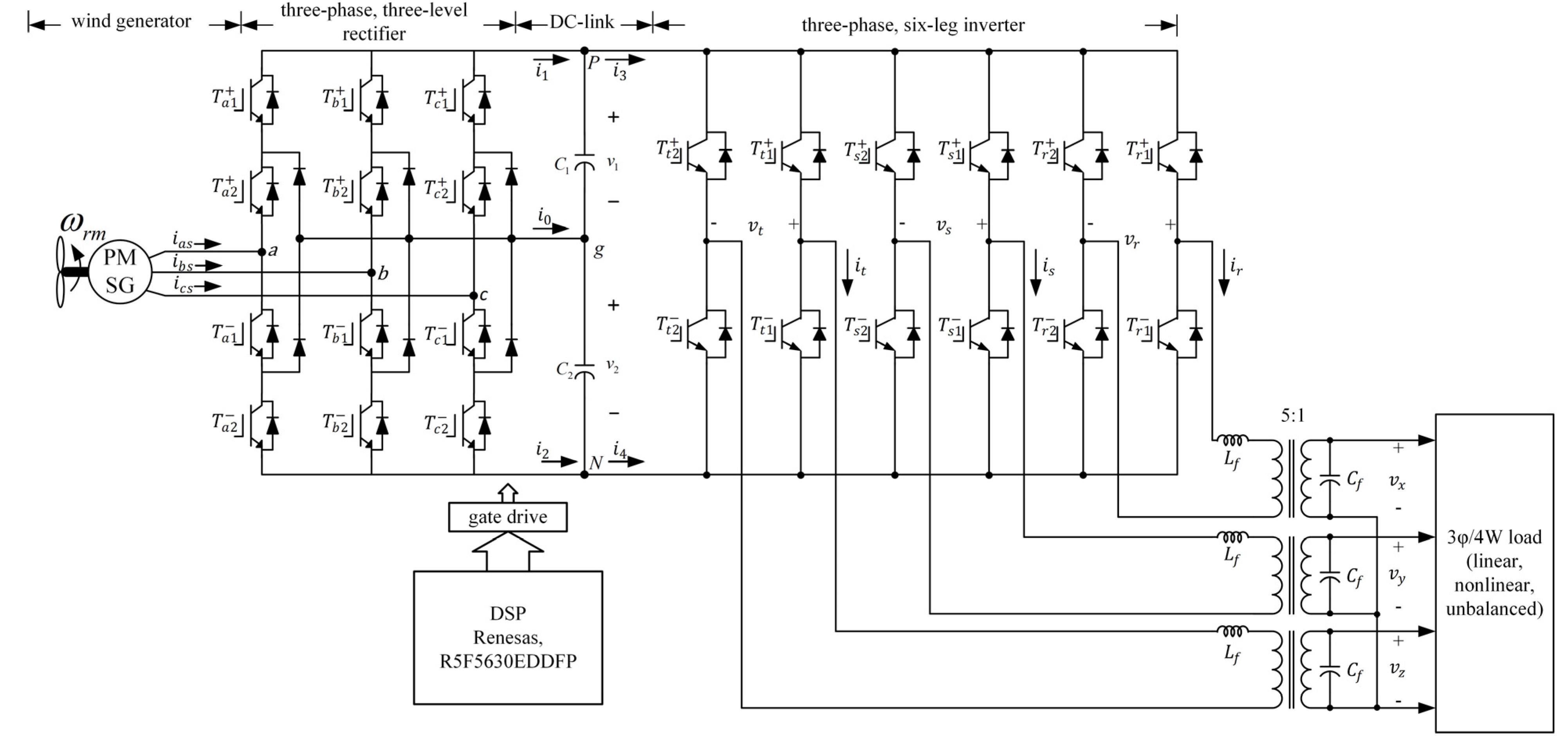
2.4. Three-Phase, Six-Leg Inverter

A schematic diagram of the three-phase, six-leg inverter with phase-r consideration is shown in Figure 8. The inverter has the conventional single-phase, full-bridge structure. Assume that
d x = { 1 T x + : O N   T x : O F F 0 T x + : O F F T x : O N  
where x denotes r 1 , r 2 , s 1 , s 2 , t 1 , or t 2 . Therefore, the equivalent circuit of phase-r shown in Figure 9 can be obtained. A similar result can be obtained for phase-s and phase-t. The switching functions of the three-phase voltages v r , v s , and v t and the DC-link current i d c can be written as
v r = ( d r 1 d r 2 ) v d c
v s = ( d s 1 d s 2 ) v d c
v t = ( d t 1 d t 2 ) v d c
i 3 = i r 1 + i r 2 + i s 1 + i s 2 + i t 1 + i t 2
where i r 1 = d r 1 i r , i r 2 = d r 2 i r , i s 1 = d s 1 i s , i s 2 = d s 2 i s , i t 1 = d t 1 i t , and i t 2 = d t 2 i t ; v d c is the DC-link voltage. According to Equation (29), the DC-link current i 3 can be obtained as
i 3 = ( d r 1 d r 2 ) i r + ( d s 1 d s 2 ) i s + ( d t 1 d t 2 ) i t
Equations (26)–(28) indicate that the instantaneous voltages of each phase are v d c , 0, and v d c , where the voltage of phase-r can be written as
v r = { v d c d r 1 = 1 , d r 2 = 0 0 d r 1 = 0 ,   d r 2 = 0 or   d r 1 = 1 ,   d r 2 = 1 v d c d r 1 = 0 , d r 2 = 1
Therefore, the output voltage of phase-r can be determined by the states d r 1 and d r 2 and the DC-link voltage. If the DC-link voltage is constant, d r 1 and d r 2 can be varied to adjust the output voltage of phase-r. The output voltages for phase-s and phase-t can be similarly obtained. Equations (26)–(28) were used in this study to implement a three-phase, six-leg inverter.
Figure 8. Power circuit of the three-phase, six-leg inverter (phase-r).
Electronics 04 00339 g008
Figure 9. Equivalent circuit of the three-phase, six-leg inverter (phase-r).
Electronics 04 00339 g009
The inverter power circuit with appropriate control can provide three different voltage levels to the load. This is illustrated by the following four modes of operation:
(1)
When v r * > v t r i , T r 1 + is ON and T r 1 is OFF, leading to v r 1 N = v d c
(2)
When v r * < v t r i , T r 1 + is OFF and T r 1 is ON, resulting in v r 1 N = 0
(3)
When v r * > v t r i , T r 2 + is ON and T r 2 is OFF, resulting in v r 2 N = v d c
(4)
When v r * < v t r i , T r 2 + is OFF and T r 2 is ON, leading to v r 2 N = 0
The voltage ratings of switches are identical and equal to v d c . The antiparallel diodes across the switches enable continuous current to flow and thus facilitate maintaining a sinusoidal output current.
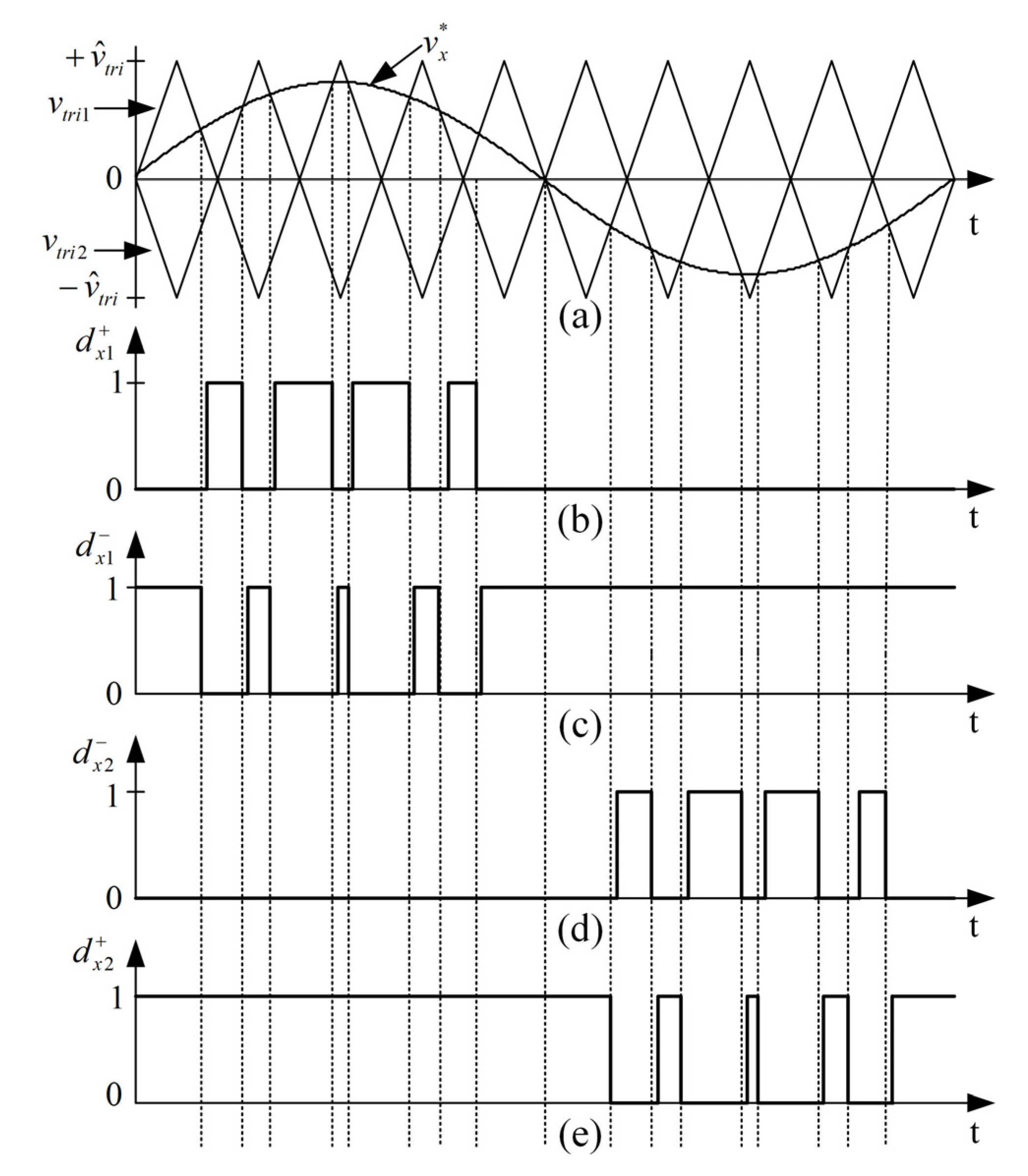
To control the three-phase inverter, a multicarrier disposition PWM technique is used. Gating signals for the power transistors are generated by comparing the commanding signal magnitudes of v r * and v r * with a contiguous carrier wave. Figure 10 shows that there are four switching modes corresponding to the level of the commanding signal, as shown in Figure 10b–d. In the first mode of operation, the magnitude of the carrier wave is compared with the commanding signal magnitudes. If the commanding signal magnitude is lower than the carrier wave magnitude, the second mode of operation, in which the switching pattern produced by comparing the carrier wave magnitude with the commanding signal magnitude, is performed. Similarly, gating signals for the power transistors in the third and fourth modes of operation can be obtained by comparing the carrier wave magnitude with the magnitudes of v r * and v r * , respectively. Figure 10d shows that the switching pattern of the three-phase, six-leg inverter is generated by the aforementioned four modes of operation and that the average output voltage v r is sinusoidal. The switching loss of the inverter can be reduced by reducing the switching frequency or by reducing the instantaneous value of the current or voltage in the switching period. Conventional bipolar modulation results in high commutation losses because the four switches are modulated at a high frequency in all modulation cycles. However, in unipolar modulation, only v d c and 0 are presented in the positive half-cycle. Therefore, unipolar modulation is more efficient for practical applications.
Figure 10. Switching pattern of the three-phase, six-leg inverter (phase-r).
Electronics 04 00339 g010

2.5. Design of Voltage Regulator

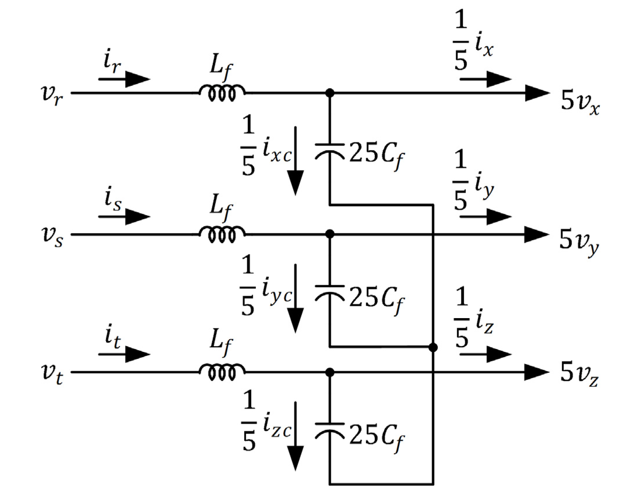
The low-pass filter for the three-phase, six-leg inverter shown in Figure 1 was implemented using three inductors, capacitors, and transformers. The inductors and capacitors are connected in series and in parallel on the primary and the secondary sides of each transformer, respectively. Assume the turn ratios of the transformers to be 5. To simplify the analysis of the transformer, the equivalent copper, iron losses, leakage, and excitation inductors are neglected, as shown in Figure 11. Therefore, the three-phase voltage and current equations can be written as
v r s t = 5 v x y z + L f ˜ d d t i r s t + R f ˜ i r s t
i x y z c = C f ˜ d v x y z d t
i x y z = 5 i r s t i x y z c
where
  • v x y z = [ v x v y v z ] T : phase voltages on the secondary sides of transformers;
  • v r s t = [ v r v s v t ] T : phase voltages on the primary sides of transformers;
  • i x y z = [ i x i y i z ] T : phase currents on the secondary sides of transformers;
  • i r s t = [ i r i s i t ] T : phase currents on the primary sides of transformers;
  • i x y z c = [ i x c i y c i z c ] T : currents to capacitors;
  • R f ˜ = [ R f 0 0 0 R f 0 0 0 R f ] ;
  • L f ˜ = [ L f 0 0 0 L f 0 0 0 L f ] ;
  • C f ˜ = [ C f 0 0 0 C f 0 0 0 C f ]
  • R f : equivalent resistors of the line and inductor;
  • L f : inductor in the low-pass filter;
  • C f : capacitor in the low-pass filter.
For model analysis and controller design, the three-phase voltages, currents, and switching functions can be transformed to a q-d-0 rotating frame. This yields
[ f q r f d r f 0 r ] = 2 3 [ cos θ e cos ( θ e 2 π 3 ) cos ( θ e + 2 π 3 ) sin θ e sin ( θ e 2 π 3 ) sin ( θ e + 2 π 3 ) 1 2 1 2 1 2 ] [ f a f b f c ]
[ f a f b f c ] = [ cos θ e sin θ e 1 cos ( θ e 2 π 3 ) sin ( θ e 2 π 3 ) 1 cos ( θ e + 2 π 3 ) sin ( θ e + 2 π 3 ) 1 ] [ f q r f d r f 0 r ]
where θ e is the transformation angle of the rotating frame and f denotes voltages, currents, or switching functions.
Figure 11. Equivalent circuit of the low-pass filter.
Electronics 04 00339 g011
According to Equations (32) and (35), the voltage equations can be derived as
v q s e v q r e = 5 ( R f i q s e + L f d i q s e d t + ω e L f i d s e )
v d s e v d r e = 5 ( R f i d s e + L f d i d s e d t ω e L f i q s e )
v 0 s e v 0 r e = 5 ( R f i 0 s e + L f d i 0 s e d t )
where v q s e , v d s e , and v 0 s e are the q-d-0 axis voltage outputs of the power inverter; v q r e , v d r e , and v 0 r e are the q-d-0 axis voltage outputs of the transformers; and i q s e , i d s e , and i 0 s e are the q-d-0 axis current outputs of the power inverter. Similarly, the current equations can be derived from Equations (33) and (35) as
i q s e = C f d v q r e d t + ω e C f v d r e + i q L e
i d s e = C f d v d r e d t ω e C f v q r e + i d L e
i 0 s e = C f d v 0 r e d t + i 0 L e
where i q L e , i d L e , and i 0 L e are the q-d-0 axis currents on the load side. Equations (37)–(42) were used in this study to design the voltage regulator.
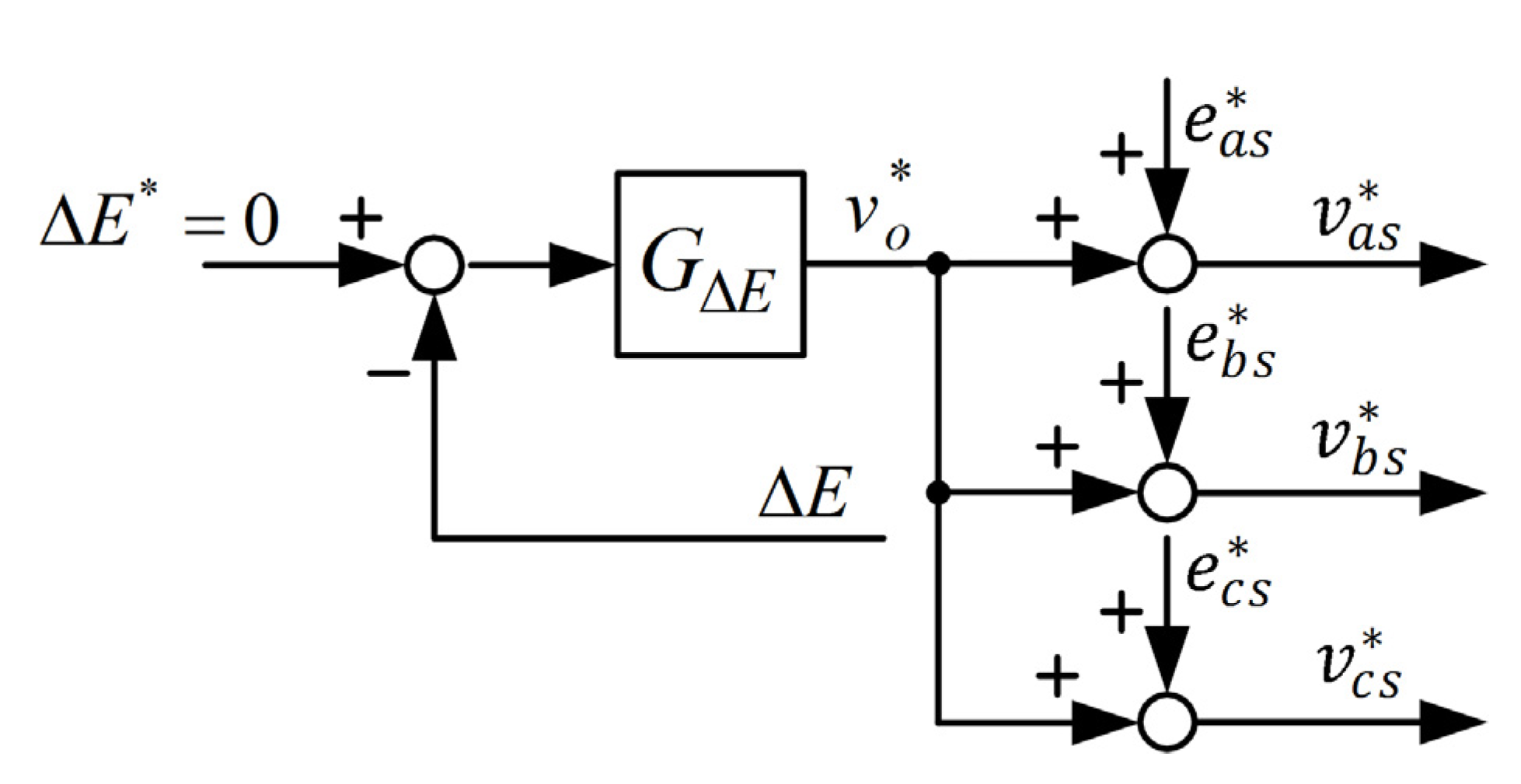
The three-phase source commands can be written as
v x * = V m * sin ω e t
v y * = V m * sin ( ω e t 2 π 3 )
v z * = V m * sin ( ω e t + 2 π 3 )
Therefore, the three-phase source commands in the rotating frame with θ e = ω e t can be expressed as
v q r e * = 0
v d r e * = V m *
v 0 r e * = 0
where V m * 
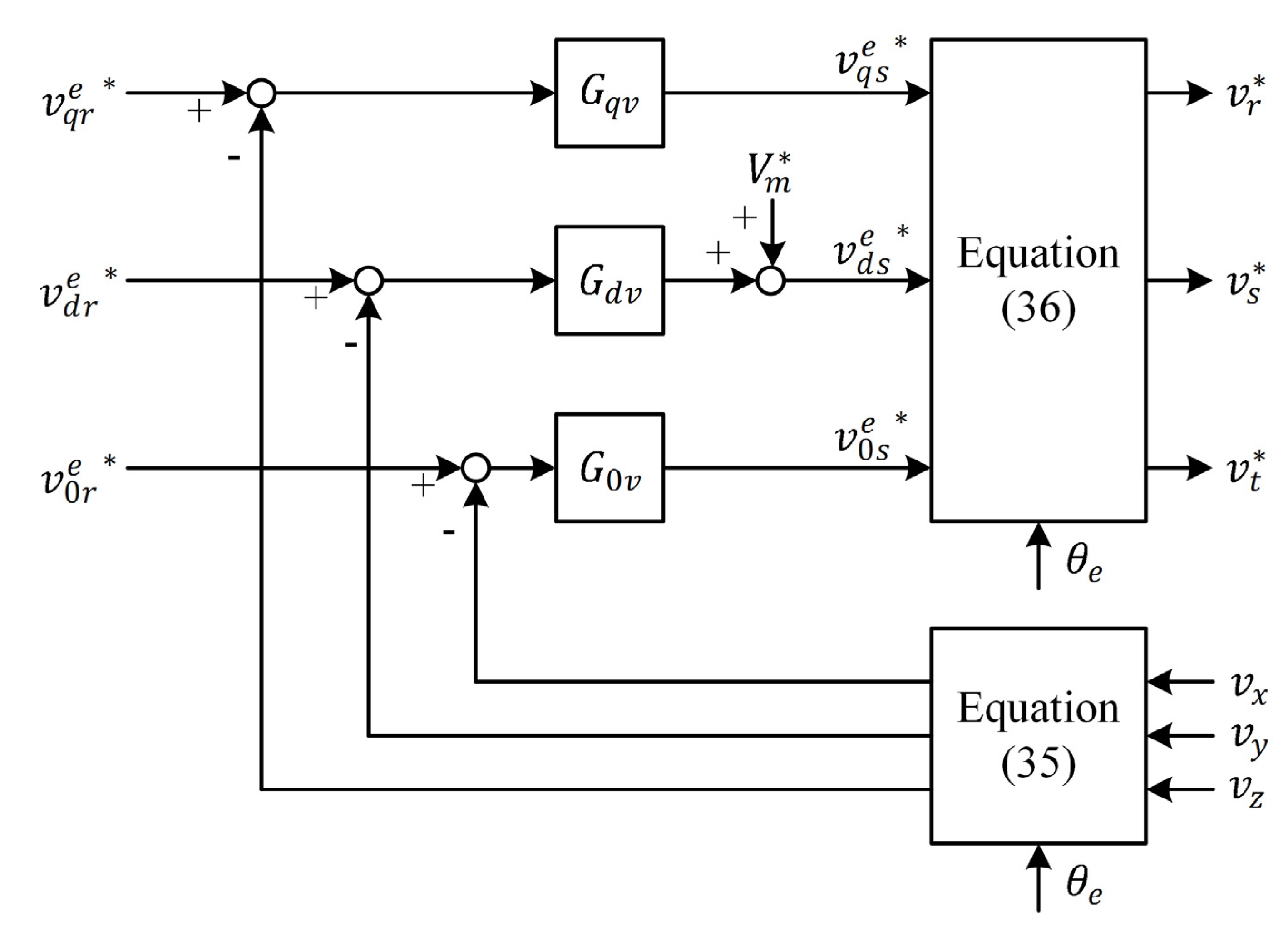
is the peak voltage. Equations (37)–(42) show that the voltage and current equations in the rotating frame are time invariant. Equations (46)–(48) were used to derive the block diagram of the voltage regulator and calculate the voltage comments of the power inverter shown in Figure 12. The proportional-integral controls for voltage regulators of a power inverter are given by
G y v ( s ) = k p y + k i y s
where y denotes q, d, or 0; k p y and k i y are the proportional-integral gains of the q- and d-axis voltage regulators. In the following section, an experimental evaluation of the proposed system is described.
Figure 12. Control block diagram of the voltage regulator.
Electronics 04 00339 g012

3. Experimental Results

To verify the performance of the proposed system, an experimental prototype of a 75 kW wind power system involving the PMSG was constructed using the following parameters:
L f = 1.5  mH and C 1 = C 2 = 3760  μF
The machine and electric parameters of the PMSG are presented in the Appendix.
The effective operating speed of the PMSG is between 50 and 75 rpm. If the PMSG is operated above 75 rpm or below 50 rpm, the control system is shut down to avoid damaging the PMSG. Furthermore, the maximum loading capacity is determined by the rated power of the PMSG. The aforementioned DSP is used to implement the control schemes. The sampling period for feedback signals and program execution corresponds to a sampling frequency of 2.5 kHz. The power converter was constructed using an IGBT operating at 2.5 kHz. Figure 13 shows the measured generator output voltage v a s , output current i a s , DC-link voltage v d c , and voltage error Δ E between the upper and lower capacitors of the proposed system; R 1 and R 2 are 20  Ω for a rotor speed of 70 rpm in standalone operation. At the output level of 72 kW, v a s and i a s remain in phase, whereas the total harmonic distortion ( T H D i ) of the output current i a s is 3.2%. Furthermore, the voltage error Δ E between the upper and lower capacitors is almost zero in the steady state. Figure 14 shows the transient response of the proposed system under unbalanced loads of 60 Ω and 30  Ω , respectively. Figure 14 shows that the voltage error Δ E between the upper and the lower capacitors is set to be almost zero through instantaneous power balance control.
Figure 13. Experimental results of the proposed system for resistive loads R 1 = R 2 = 20  Ω : (a) generator phase-voltage v a s and line current i a s ; (b) DC-link voltage v d c ; and (c) voltage error between the upper and the lower capacitors.
Electronics 04 00339 g013
Figure 14. Experimental results of the proposed system for resistive loads R 1 = 30  Ω and R 2 = 60  Ω : (a) generator output current i a s ; (b) DC-link voltage v d c ; (c) voltage error between the upper and the lower capacitors.
Electronics 04 00339 g014
Figure 15 shows the output voltages v x , v y , and v z and the output currents i x , i y , and i z of the transformers in the proposed system for a rotor speed of 50–75 rpm with three-phase unbalanced resistive loads of 10 kW. The values of three-phase unbalanced resistive load are 8 Ω, 0 Ω and 0  Ω , respectively. The output voltages v x , v y , and v z are balanced and almost sinusoidal. This can be justified from Figure 15a, which shows the voltage harmonic distortions of v x , v y , and v z to be 4.11%, 4.08%, and 3.95%, respectively; these distortions satisfy IEEE Std. 519. The measured efficiency of the entire system reached 91% because the efficiencies of the three-phase, three-level rectifier and three-phase, six-leg inverter are 97% and 96%, respectively. The inherent system losses, such as element loss and stray loss, exist in practice. Finally, the voltage error between the upper and the lower capacitors is approximately zero, thereby validating the proposed control algorithm.
Figure 15. Output voltages of the transformers connected to unbalanced loads for a 10 kW power output: (a) output voltages of the transformers; (b) output current of the x-phase; and (c) output current of the y-phase.
Electronics 04 00339 g015

4. Conclusions

A three-level power converter that can be connected to a wind generator is proposed. Regardless of the wind speed variation, the proposed system provides a constant power at the output and balanced voltages across the DC-link capacitors. It can function satisfactorily in standalone mode and supply power to three-phase, four-wire loads. In the proposed rectifier, three-leg switches are used to generate a DC output. Both inner-loop current switching control and outer-loop voltage control are achieved by decoupling the converter system along the q-axis and d-axis of a synchronous rotating frame. Furthermore, the neutral-point-clamped architecture is used to determine three-phase voltage commands; errors in the voltages across the upper and lower DC-link capacitors are detected for achieving instantaneous power balance control between the generator and the load. A novel three-phase, six-leg inverter is introduced with the main objective of supplying balanced voltages and performing step-down operation. Steady-state and average-value modeling of the inverter are presented. In addition, an inverter with an output transformer was designed and implemented to eliminate the harmonic components of the output voltage. A voltage feedback loop for the inverter was also designed and implemented to provide a sinusoidal output voltage and achieve high dynamic performance even when the rotor speed varies. The experimental results showed that the total harmonic distortion of the inverter was considerably reduced. To summarize, the proposed system offers the following advantages: low cost, low harmonic distortion, high reliability, and stable output voltages.

Acknowledgments

The author wishes to express his sincere appreciation to UCHI OPTOELECTRONIC (M) SDN. BHD. for supporting this research. The author would also like to thank the anonymous reviewers for their valuable comments and suggestions to improve the quality of the paper.

Conflicts of Interest

The author declares no conflict of interest.

Appendix

Table A1. Machine and Electric Parameters of PMSG.
Machine ParametersElectric Parameters
Rated speed: 100 rpm λ m ' = 60 V-s/rad
Rated torque: 1000 nt-m r s = 0.3  Ω
Rated power: 75 kW L s = 0.5 mH
Line voltage: 1.2 kV
Line current: 36 A
Pole number: 24

References

  1. Leon, A.E.; Solsona, J.A. Sub-Synchronous interaction damping control for DFIG wind turbines. IEEE Trans. Power Syst. 2015, 30, 419–428. [Google Scholar] [CrossRef]
  2. Cardenas, R.; Pena, R.; Alepuz, S.; Asher, G. Overview of control systems for the operation of DFIGs in wind energy applications. IEEE Trans. Ind. Electron. 2011, 60, 2776–2798. [Google Scholar] [CrossRef]
  3. Arbi, J.; Ghorbal, M.J.-B.; Slama-Belkhodja, I.; Charaabi, L. Direct virtual torque control for doubly fed induction generator grid connection. IEEE Trans. Ind. Electron. 2009, 56, 4163–4173. [Google Scholar] [CrossRef]
  4. Mohammadpour, H.A.; Santi, E. Modeling and Control of Gate-Controlled Series Capacitor Interfaced With a DFIG-Based Wind Farm. IEEE Trans. Ind. Electron. 2015, 62, 1022–1033. [Google Scholar] [CrossRef]
  5. Abad, G.; Rodriguez, M.A.; Poza, J. Two-Level VSC based predictive direct torque control of the doubly fed induction machine with reduced torque and flux ripples at low constant switching frequency. IEEE Trans. Power Electron. 2008, 23, 1050–1060. [Google Scholar] [CrossRef]
  6. Zhou, L.; Jinjun, L.; Sizhan, Z.; Zhu, Y.; Liu, F. Feed-Forward control for permanent magnet synchronous generator based wind turbine aimed at output power smoothing. In Proceedings of the 2013 IEEE in ECCE Asia Downunder (ECCE Asia), Melbourne, Australia, 3–6 June 2013; pp. 1305–1309.
  7. Carranza, O.; Figueres, E.; Garcera, G.; Ortega, R.; Velasco, D. Low Power Wind Generation System based on variable speed permanent magnet synchronous generators. In Proceedings of the 2011 IEEE International Symposium on Industrial Electronics (ISIE), Gdansk, Poland, 27–30 June 2011; pp. 1063–1068.
  8. Tammaruckwattana, S.; Ohyama, K. Modeling and simulation of permanent magnet synchronous generator wind power generation system using boost converter circuit. In Proceedings of the 2013 15th European Conference on Power Electronics and Applications (EPE), Lille, France, 2–6 September 2013; pp. 1–10.
  9. Hussein, M.M.; Orabi, M.; Ahmed, M.E.; Sayed, M.A. Simple sensorless control technique of permanent magnet synchronous generator wind turbine. In Proceedings of the 2010 IEEE International Conference on Power and Energy (PECon), Kuala Lumpur, Malaysia, 29 November–1 December 2010; pp. 512–517.
  10. Bhat, A.H.; Langer, N. Capacitor Voltage Balancing of Three-Phase Neutral-Point-Clamped Rectifier Using Modified Reference Vector. IEEE Trans. Power Electron. 2014, 29, 561–568. [Google Scholar] [CrossRef]
  11. Vieira, P.K.P.; da Silva, E.R.C. A digital current control strategy for One-Cycle Control based Active Neutral Point Clamped rectifier and three derived topologies. In Proceedings of the 2012 10th IEEE/IAS International Conference on Industry Applications (INDUSCON), Fortaleza, Brazil, 5–7 November 2012; pp. 1–7.
  12. Zhu, Y.-F.; Zheng, Z.; Yang, H.-Z.; Tan, K. A new control method for neutral-point-clamped three-level PWM rectifiers. In Proceedings of the 2011 International Conference on Consumer Electronics, Communications and Networks (CECNet), Xianning, China, 16–18 April 2011; pp. 983–986.
  13. Fei, W.; Qiongxuan, G.; Yanmin, Z. A New control strategy for neutral-point-clamped active rectifier based on DSP-FPGA. In Proceedings of the ICEMS 2009, International Conference on Electrical Machines and Systems, Tokyo, Japan, 15–18 November 2009; pp. 1–4.
  14. Yingchao, Z.; Jiangtao, L.; Yongchang, Z.; Ting, L.; Zhengming, Z.; Liping, J. TABLE-BASED direct power control for three-level neutral point-clamped pulse-width modulated rectifier. IET Power Electron. 2013, 6, 1555–1562. [Google Scholar]
  15. Dahono, P.A.; Satria, A.; Nurafiat, D. Analysis of DC current ripple in six-legs twelve-devices inverters. In Proceedings of the 2012 International Conference on Power Engineering and Renewable Energy (ICPERE), Bali, Indonesia, 3–5 July 2012; pp. 1–6.
  16. Hwang, J.-C.; Wei, H.-T. The Current Harmonics Elimination Control Strategy for Six-Leg Three-Phase Permanent Magnet Synchronous Motor Drives. IEEE Trans. Power Electron. 2014, 29, 3032–3040. [Google Scholar] [CrossRef]

