Article

On Using Ilities of Non-Functional Properties for Subsystems and Components

1
Commercial Aviation Services Division, The Boeing Company, Seal Beach, CA 90740, USA
2
Department of Electrical and Computer Engineering, Colorado State University, Fort Collins, CO 80523, USA
*
Author to whom correspondence should be addressed.
Systems 2017, 5(3), 47; https://doi.org/10.3390/systems5030047
Submission received: 25 April 2017 / Revised: 7 July 2017 / Accepted: 23 July 2017 / Published: 28 July 2017

Abstract

:
The use of ilities for systems engineering of subsystems and components is investigated. Prior work on ilities has emphasized or restricted their application to system level, non-functional properties. The premise of this work is that ilities can be applied with benefit, and in some cases out of necessity, to lower levels of systems as well. The veracity of this premise is established by providing examples that demonstrate how some ilities are passed and used as a non-functional property of electrical and structural subsystems in aircraft. It is further demonstrated that flowing ilities down to the subsystem level is not only a useful practice for systems engineers, it can also be an essential step to ensure that customer needs are actually met by the system under design or service. Systems engineers often lack the detailed knowledge of the subsystems or components required to translate ilities into functional requirements. Thus, the system ilities are passed down and translated from non-functional to functional requirements by subject matter experts. We first discuss the definition, characteristics and scope of ilities. Then, we formulate the application of ilities at a subsystem level. Next, we show aircraft engineering examples for ilities applications. The application process is formalized with diagrams, and ilities’ relation to system architecture engineering is discussed. The work concludes with a summary and suggestions for future work.

1. Introduction

Ilities are a way for systems engineers to capture customer needs early in the system lifecycle, prior to the development of functional requirements. Customer needs include the developmental, operational, and support requirements a program must address. Examples are reliability, quality, safety, maintainability, durability, manufacturability, and testability, to name a few [1]. They are not specific requirements of the system; rather, they are properties of the system that are important to customers and other stakeholders. Each ility may have a variable level of importance to each stakeholder, and one function of the systems engineer is to work with the team chartered with implementing the system to develop a solution that balances all stakeholder interests. The ilities are then translated to functional requirements.
A more restrictive definition of ilities limits them to only system level non-functional requirements. For instance, they have been defined as “desired properties of systems, such as flexibility or maintainability, that often manifest themselves after a system has been put to its initial use. These properties are not the primary functional requirements of a system’s performance, but typically concern wider system impacts with respect to time and stakeholders than are embodied in those primary functional requirements” [2]. On this understanding, ilities are limited to system level requirements and descriptions. A similar definition of ilities was used in [3] where ilities were restricted to stakeholders’ needs in relation to the level of service. In their approach, ilities are used in a quality function deployment (QFD) matrix, which transforms the qualitative user demands into quantitative parameters. This approach provides a valuable tool to systems engineers in managing ilities, but it is applied only at a top system level, and does not flow ilities to lower parts of the system.
This same approach of limiting ilities to system level analysis exists in software development. For instance, this approach is taken in [4], which uses non-functional requirements for software architecting. On their approach, each ility is listed in a table that can be used to assess the ability of the architecture to achieve desired system aspects for space mission flight software. While this is a valuable tool for software development, the ilities are only applied at the system architecting level.
The central proposal in this work is that for complex systems, ilities can be applied with benefit to not only system level properties, but also to subsystems as well. The veracity of this premise is established by providing examples that demonstrate how ilities are flowed down as a non-functional property to several subsystems in an aircraft system. Passing ilities down to the subsystem level is not only a useful practice for systems engineers, it can also be an essential step to ensure customer needs are actually met by the system. Systems engineers often lack the detailed knowledge of subsystems or components required to translate ilities into functional requirements. As a result, for complex systems, ilities are flowed down so that subject matter experts can translate them from non-functional to functional requirements, and ensure that customer needs are met. The idea that ilities can be used not only at the system level, but also at the subsystem level for complex systems is the central focus of this work.
In order to discuss this central focus in a proper context, we make the following contributions in this paper:
  • We explore the emergence characteristics of ilities in Section 2.
  • We develop an ilities application method for subsystems in Section 3. We leverage the prior works on the Systems of Systems Architecting with Ilities (SAI) method to achieve this goal.
  • We show examples for how ilities of complex systems are flowed down to subsystems or components in Section 4. The point of this section is to establish the legitimacy of the premise.
  • We explore the ilities usages in the context of system architecture principles and present the dual functional nature of ilities in Section 5.
  • We examine the correlation between ilities and traditional systems architecture engineering in Section 6. A summary and suggestions for additional work are presented in Section 7.

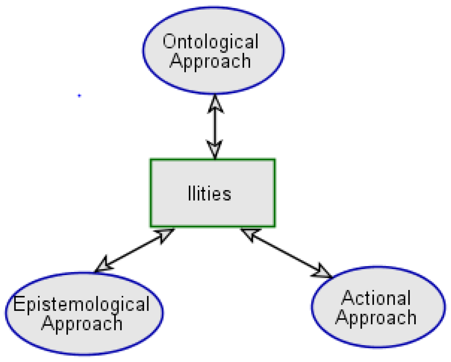
2. Characterization and Scope of Ilities in Systems Engineering

To set the scene for this work, we begin with a brief overview of ilities as a system level emergent property. Ilities are quality attributes that emerge when engineering systems are integrated and operated, for which approaches are available in different domains [5,6,7] with a variety of definitions [8,9,10,11,12]. We note that when a system is in operation, new properties emerge due to interactions between parts of the system. The emergent properties of a system have been noticed as early as in the fourth century BC, when Aristotle stated that the “whole is something beside the parts [13].” Interest in this emergent property of a system resurged in the form of modern emergence theory in recent years in a wide range of disciplines, such as evolutionary biology, complexity science, artificial intelligence, cognitive science, and others [14,15,16,17,18,19,20]. Since ilities are one of the emergent properties of engineering systems, characteristics and usage of ilities may also be studied with emergence theory. Emergence refers to the process of unfolding of what is implied within the parts of systems as they are integrated. Crawley et al. [21] proposed 26 principles of system architecture, of which the first one is the principle of emergence. In their analysis of the emergence principle, they proposed that four emergence classes could appear when an engineering system operates. They are: functions, performance, ilities, and emergencies of the system. Emergence is the magic and power of a system, and the goal of systems engineering is to study and utilize these emergent properties of a system. The first two classes of emergence, functions and performance, create value for a system immediately; ilities, on the other hand, create value over a lifecycle of a system [22]. The fourth class of emergence, emergency, appears when something goes wrong in the way the system operates. Among these four classes of emergence, ilities are the main focus in this work.
We wish to discuss ilities within the context of two domains and propose three approaches to study them. One of Crawley’s principles is that of dualism, which states “all built systems inherently and simultaneously exist in the physical domain and the informational domain.” As ilities emerge in the physical domain, their pattern in physical form is abstracted as data in the informational domain, which is then decoded by the user. In a similar manner, Blanchard and Fabrycky [23] proposed a dichotomy of physical systems and conceptual systems. We follow and extend the work of these authors and examine the two systems closely. This consideration may be called an ontological viewpoint or a theory of being, in which both physical domain and informational domain are considered.
The Crawley’s principle of dualism also demands examination of the relationship between the two domains. The principle of dualism restricts the relation between the two in a sense that the physical domain supports the informational domain by sustaining the form, but not necessarily the function. Since the function of the system includes user perception, we expand the meaning of the dualism principle one step further and pay close attention to the perceptional aspect of the informational domain. The information domain enables perception of the physical system, which may be called an epistemological viewpoint or theory of perception. The theory of perception examines how the informational domain is related to the physical domain as far as how two domains support each other and how one domain understands the other. Traditionally, the relationship between the two has been approached from the theory of knowledge, of which coherence theory is representative. Another theory of knowledge is correspondence theory, which asserts that there is one-to-one correspondence between the two domains.
Information domain also affects the physical domain in terms of design, testing, and manufacturing, which may be called an actional viewpoint, or a theory of action. These three approaches on ilities study are illustrated in Figure 1 using Object Process Methodology (OPM) conceptual modeling.
For simple engineering systems, it is not necessary to consider subsystems and their emergence properties. However, for complex engineering systems, such as socio-technical systems, ilities as system level emergent properties are manifest at the subsystem level as well, since subsystems also possess ilities emergence characteristics in a similar manner as systems do. The purpose of this work is to examine how ilities are at work and operate at the subsystem level for engineering development and engineering services. As an example, let’s consider a service situation for an emergency light subsystem in the aircraft galley cabin. The emergency light subsystem is part of an aircraft system. Typically, there are 12 emergency lights on the galley cabinet subsystem in close proximity to the floor—four on the forward panel, two on each side panel, and four on the aft panel. All 12 lights are to be installed and operational per delivery configuration. If one or two lights on the aft panel are found non-operational, the situation may be analyzed with a trade-off of ilities technique at the subsystem level. We may argue the emergency subsystem should be operational with all 12 lights illuminated from the quality standpoint. We may say, on the other hand, the aft light entities can be non-operational from the safety standpoint. As passengers walk to the exit door, the lights on the front panel and side panels offer the required illumination, and the aft lights are less important. Since the aft lights are non-critical to operation in an emergency situation, the aircraft can be dispatched without the aft lights, under the condition that the aft lights will be fixed at a later opportune time. We also may raise a question from the reliability standpoint: why are the aft lights at the component level non-operational to begin with? Thus, the maintainability as an ility should be considered for the defective lights. This is an example of four ilities (quality, safety, reliability and maintainability) that are emergent and traded off at the subsystem and component levels for a dispatch decision. A summary of ilities for trade-off is shown in Table 1.
This example illustrates that the scope of ilities can be expanded to the subsystem and component levels. The definition of ilities has not been changed, but the scope of ilities usage is expanded. Users and most stakeholders are generally concerned about system level properties, and are less concerned about subsystems for ilities. The contention of this work is that systems engineers and architects should use ilities for subsystems to maximize the ilities engineering benefits. Instead of ilities being converted from system level non-functional requirements to system level function requirements only, they can be passed down to lower levels of the system for conversion to functional specifications. Stakeholders could and should view ilities not only as system level properties, but also as subsystem level properties. This practice frees up certain restrictions existing in ilities engineering and offers significant benefits as systems engineering practices are applied to subsystems and components engineering. Another benefit of the expansion of scope of ilities is that it increases the tools available to engineers and architects. It allows them to perform ilities trade studies not only at the system level, but also at the subsystem level prior to the conversion of non-functional requirements to functional requirements.

3. Ilities Application at the Subsystem Level

There are several methods for architecture development and engineering services using ilities. An inspiring paper has been published recently for Systems of Systems (SoS) architecture development using ilities called the Systems of Systems Architecting with Ilities (SAI) method [24]. Another method uses non-functional requirements and the quality function deployment (QFD) matrix to rank each of the ilities [3]. For this work, we focus on the SAI method. Although the SAI method was developed for systems of systems, the method can be applied to systems and subsystems, with proper modification. The SAI method offers a comprehensive and detailed approach to system architecting at all levels of system organization. We found that the steps of the SAI method can be closely followed and applied to subsystem situations. The eight-step SAI method is reduced to a six-step method as shown in Figure 2 when it is adapted to subsystems. These steps explained below:
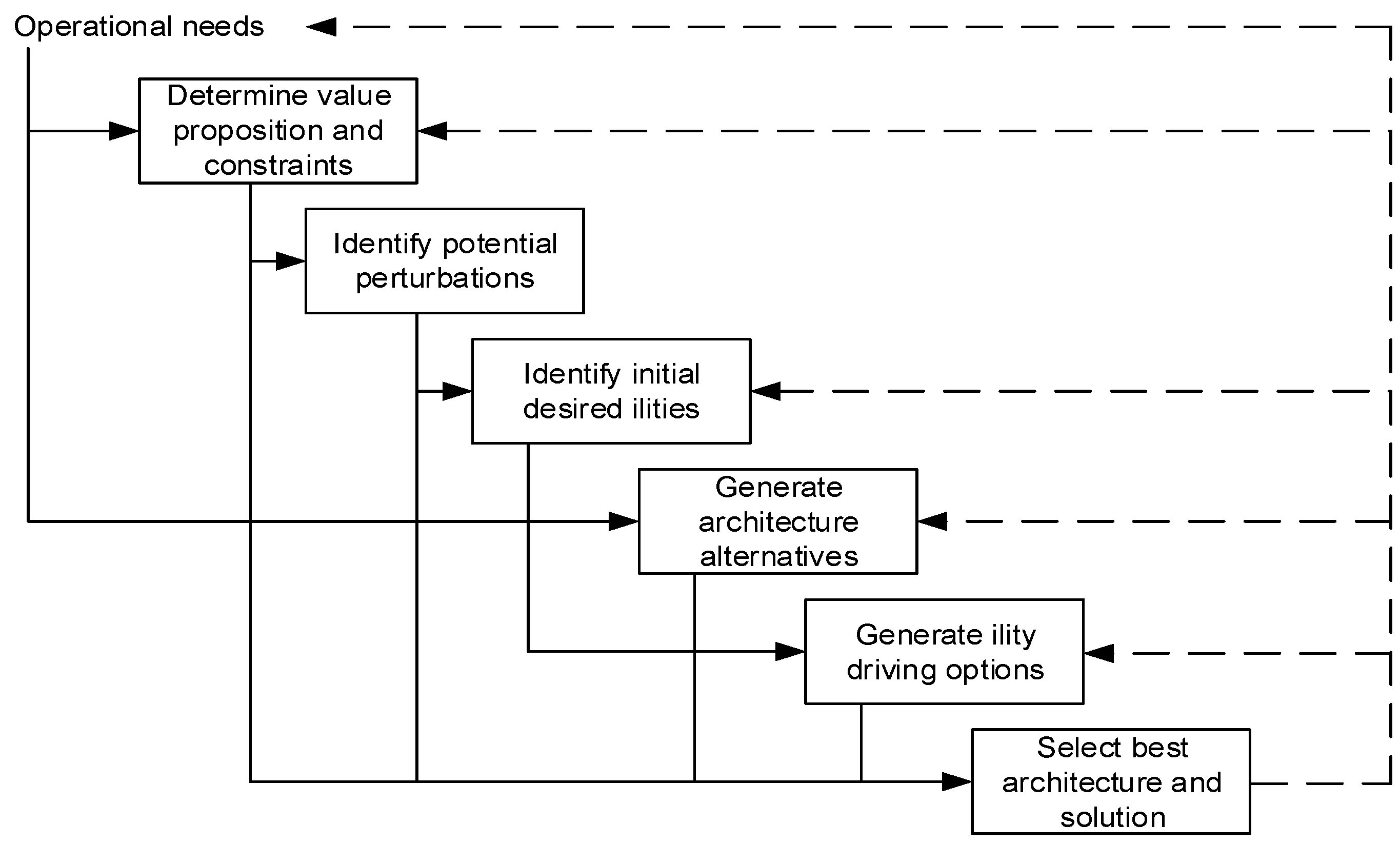
  • Step 1: In the first step, overall values and constraints are called out for systems and subsystems. Value proposition is identified and captured for their architecture. Key stakeholders are engaged and their needs and design constraints are noted. An example of value proposition at a system and subsystem levels for aircraft is found in the Federal Aviation Administration (FAA) value statement about safe transportation for the general public.
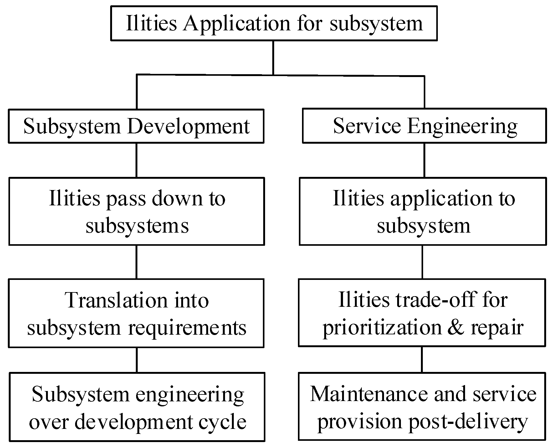
  • Step 2: Potential perturbations and risk for subsystems are investigated and identified for both the systems development phase and for the service engineering (post-delivery) phase. Potential perturbations in the system needs lead to subsystem design, and those identified post-delivery lead to maintenance and repair of the subsystems. One example of dynamic and uncertain environmental perturbations is the electromagnetic and lightning effects on aircraft systems, subsystems and components. Perturbations and risk are also emergent properties of systems or subsystems.
  • Step 3: Initial desired ilities are studied: list ilities that promote the desired long-term behavior of the subsystems. An examination of relevant perturbations in step 2 could generate possible desired ilities. An example of initial desired ilities in aircraft may include safety, quality, reliability or maintainability.
  • Step 4: Subsystem architecture alternatives are set up: the purpose of this step is to suggest various architectures for the value proposed in step 1. These alternatives comprise a set of architecture solutions. An example of architecture alternatives in aircraft may include design options for electromagnetic interference (EMI) hardening.
  • Step 5: Ility-driving options are produced: this step enables the investigation of the solution space in step 4, and provides initial architectures that promote the long-term values of the desired ilities. An example of solution space in our context could include grounding, shielding and bonding options at various levels.
  • Step 6: Alternative architectures are evaluated for their values, and analyzed with models. The final product of this step is the selected subsystem architecture, which manifest the desired ilities over the lifecycle by pre-delivery development or post-delivery repair and maintenance.

4. Ilities Application Example in an Aircraft Environment

In the previous sections, we proposed the idea that ilities can be applied with benefit to not only system level properties, but also to subsystems with proper adaptations and translation. In this section, we intend to describe an example of how ilities are used for aircraft subsystems. Specifically, the ilities related to the electromagnetic and lightning environment in aircraft will be used as an example [25,26]. Electromagnetic and lightning perturbations are relevant to our work due to their dynamic and probabilistic nature [27]. Numbering of the steps below corresponds to the numbering of the steps in the previous section for subsystems.
  • Step 1: In the commercial aviation domain, safe transportation is known to be a key system or subsystem level value by stakeholders such as the FAA, the European Aviation Safety Agency (EASA), aircraft manufacturers, and airliners. Furthermore, the governmental agencies provide constrains in the form of Federal Aviation Regulations (FAR) and other rules. We note that safe transportation is the primary value in aircraft operation, as the following mission and value statements of the FAA attests [28]:
    “Our continuing mission is to provide the safest, most efficient aerospace system in the world. Safety is our passion. We work so all air and space travelers arrive safely at their destinations.”
       This statement corresponds to the value proposition in step 1 of the previous section, and is a major motivating factor for every policy and regulation decision made by the FAA. This emphasis on safety is also shared by the manufacturers of commercial airliners. For instance, the vision statement of Boeing emphasizes [29]:
    “We value human life and health above all else and take action accordingly to maintain the safety of our workplaces, products and services.”
       Airliners also understand that the future of their company depends upon producing products that maintain the safety of their transportation. Based on these considerations, transportation with safety is introduced to aviation industry as one of the most critical values that cover the system level needs. The value proposition of safe transportation should be flowed down to subsystems, and subsystem level requirements should be considered to protect aircraft from environmental threats [30]. Safe transportation is a value proposition from stakeholders based on their needs and it is an emergent property of aircraft as a system.
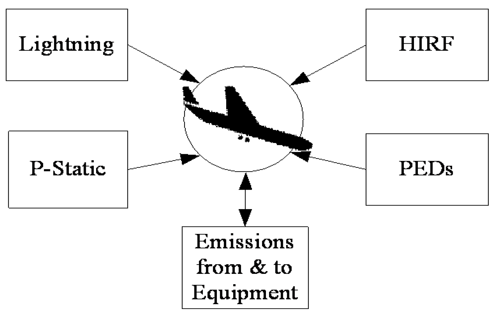
  • Step 2: Potential perturbations are identified. As an example, let’s analyze the electromagnetic and lightning perturbations. Consider how safety is applied with respect to electromagnetic environmental threats on aircraft. Aircraft subsystem engineers apply a context diagram for environmental threat categories, such as the one shown in Figure 3. It describes the uncertain and dynamic electromagnetic perturbations of aircraft such as lightning, high-intensity radiated fields (HIRF), portable electronic devices (PEDs), precipitation static (P-static), and electromagnetic interference and compatibility (EMI/EMC) [31,32]:
    Lightning: These are lighting strikes on the aircraft body during flight or while on the ground [33].
    HIRF: These are high-intensity radiated fields from sources such as airport radars, radio transmitting towers, to name a few.
    PEDs: These are portable electronic devices such as mobile phones, lap tops, and tablets which can radiate electromagnetic energy when taken onboard an aircraft [34,35].
    P-Static: This is precipitation static caused by friction between air particles and the surface of aircraft while the aircraft is flying.
    EMI/EMC: These are electromagnetic interference and compatibility among electrical and electronic equipment [31,32].
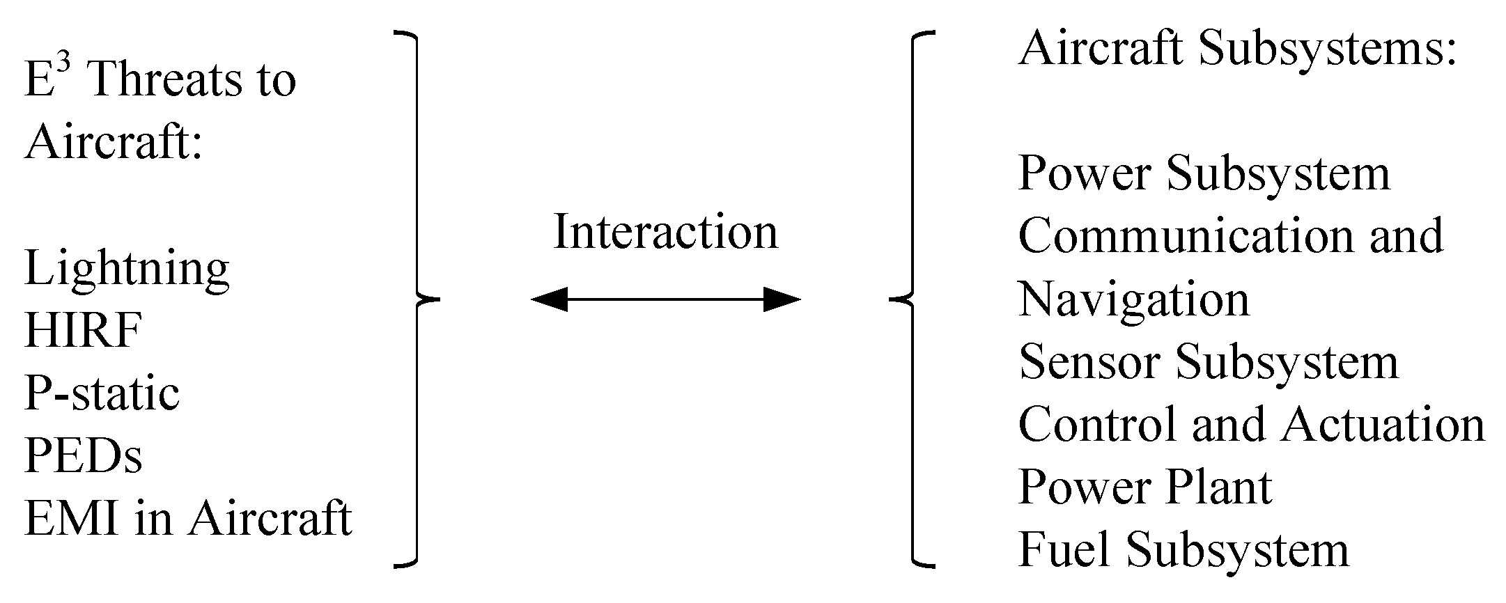
  • Step 3: We identify safety as the desired ility. Electromagnetic (EM) and lightning effects are an example of environmental perturbation with negative implications. EM and lightning effects are directly related to the safety ility of aircraft system. Safety ility is absorbed by the subsystem experts and used as a guide for decisions, specifications, and processes. Subsystem engineers consider the targets of these electromagnetic threats in aircraft, as shown in Figure 4, and translate the system level safety concerns into subsystem or component level requirements. Translation requires specific knowledge of the subsystems that are affected by EM threats. Specifically, we may consider the fuel tank and the possibility of fuel tank explosion due to lightning strikes. Safety as an emergent ility at the aircraft level is flowed down to the fuel tank subsystem, and is translated into the specific subsystem requirement, such as the probability requirement of fuel tank explosion. This process of flow downwards occurs when the subsystem and component experts develop testing methods, requirements, and qualification processes.
  • Step 4: Several development or maintenance alternatives of subsystem modules are proposed from the standpoint of decreasing vulnerability to electromagnetic and lightning threats.
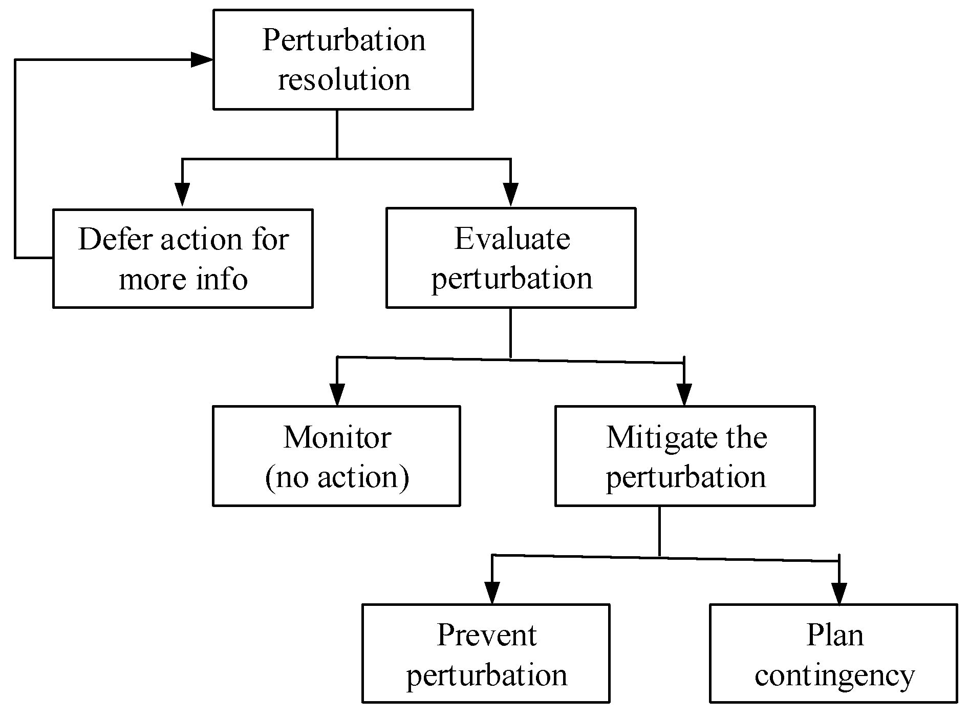
  • Step 5: Ility-driving options are generated. At the subsystem level, these options are generated from risk mitigation and resolution activities. Electromagnetic and lightning perturbation mitigation are performed based on the flow diagram in Figure 5. Examples of the lightning-related perturbation are shown below [33]. The three example situations are for (1) direct lightning effect, (2) indirect lightning effect, and (3) the fuel tank.
(1)
Direct lightning effect perturbations at the subsystem and component levels may occur as follows:
  • Melt-through damage for metal or non-metal skins (of fuel tank skin, trailing edge, painted skin, and radome).
  • Resistive heating damage (bonding strap heating or exploding wires for a navigation light on a plastic vertical fin cap, diverter straps, pitot probe air tube, and radome) or magnetic force effects (slamming together of two metal air pressure tubes in a radome mounted pitot system, in wing-tip trailing edges, bent bond straps).
  • Arcing across bonds (over riveted joints with corrosion inhibiting coating, over fasteners or bonding jumpers with inadequate current carrying capacity, over fasteners in secondary structures such as wing tips, tail cones, wheel well doors, and flight control surfaces, over adhesive bonds, over hinges and bearings resulting in pitting or welding).
  • Sparking over structural joints.
  • Punctures or flashover over non-conductive composite material (radomes, composite material skin).
  • Damage of windshields, canopies, windows (direct or swept channel attachment to heating elements and damaging the connected power circuits).
  • Damages on electrically conductive composites (carbon fiber composite skins in Zone 1 and 2 by lightning stroke currents via mechanisms of pyrolysis and shock wave; primary structures, engine nacelle and pylon, flight control surface, leading edge devices, avionics bay, wing and empennage tips, fuel tank skin).
  • Damage of propulsion system (engine cowlings or nacelles, propeller and rotor blades, gear boxes damaged by lightning attachments).
  • Rain erosion of conductive lightning protection strip (degradation of conductive frame on wings and empennage).
(2)
Lightning indirect effect perturbations may occur at the following subsystems:
  • Full authority digital engine control (FADEC).
  • Full authority electronic flight control (Fly-by-wire).
  • Supervisory control systems capable of initiating control inputs that could endanger flight safety.
  • Fully or highly-integrated cockpit instruments and displays.
  • Electronic flight instrumentation system (EFIS).
  • Aircraft electric power control and distribution system.
  • Electrical and avionics systems that include externally mounted apparatus, such as air data probes, heaters, actuators, and antennas.
(3)
Lightning strike perturbations such as fuel tank subsystem ignition or fire.
As we examine the lightning perturbations in aircraft, we note specific subsystems and components must be included in dealing with the risk. In other words, discussions of the potential damage and effects due to lightning strikes encompass the system level safety concerns as well as the subsystem and component level consideration for maintenance and risk resolution. This process is applicable to many safety/risk situations. Table 2 illustrates subsystems for this example as well as the corresponding subsystem parameters. Safety as an ility is introduced at a system level. When this ility is flowed down to the fuel subsystem, the fuel subsystem engineers or subject matter experts examine the safety parameters of the subsystem, such as fuel tank explosion probability, and develop specific requirements, such as the fuel tank explosion probability of 10−9 per flight hour. This probability can be one of several fuel tank subsystem requirements. Fuel tank component engineers conduct research on components such as wing fasteners or the fuel tank gaskets and might develop new designs for the components. The translation of safety and threat risk may generate other subsystem requirements, such as material repair requirements. The lightning strike consideration while the aircraft is parked on the tarmac may generate requirements for airplane grounding with risk acceptance/reject criteria. Other activities, such as maintenance activities for fuel injection, and maintenance activities in general, may generate other subsystem requirements.
  • Step 6: The solution space developed from the previous steps is evaluated, analyzed and the optimum solutions are selected and documented.

5. Principles of System Architecture, Dualism, and Dual Nature of Ilities

We would like to continue to develop the dualism of the conceptual system and physical system mentioned in Section 2 to advance the ilities discussion in the first half of this section. When ilities are traded off in Step 4 at a subsystem level, the system architecture principles listed in Table 3 may be used and followed [21]. For instance, safety ility is applicable to all elements of aircraft and its surroundings, per the principle of holism. Safety ility emerges in a physical system (form), but users recognize it in the conceptual system (function). This principle of dualism, Crawley’s fourth principle, is in the backdrop of the study of a conceptual system and a physical system. While implementing ilities in the conceptual system to an aircraft physical configuration, engineers take one area of concern at a time. This is an application of the principle of focus, Crawley’s third principle. While implementation is in progress, a coherence relationship should exist between the conceptual system and the implemented physical system. We may call this principle a principle of coherence. Since the importance of dualism in system architecture is generally not emphasized in public literature, we would like to review the principle of dualism further in this section. Blanchard and Fabrycky [23] make a clear distinction between a conceptual system and a physical system in their discussion of systems. A detailed analysis shows how widely the conceptual systems are spread in the engineering domain, as well as in many other areas. A conceptual system exists in the form of written and spoken languages, thoughts, electromagnetic information being transmitted in the air, electrical and non-electrical signals, and data in communication systems and computers, etc. In engineering systems, a conceptual system exists in the form of drawings, diagrams, documents, meeting logs, test data, etc. The conceptual system has the structure and hierarchy of abstraction [36]. Ilities as concepts are implemented and materialized in the form of a physical system by mapping the function to form. Lifecycle in systems engineering [37,38] may be recast as a process of this transformation of a conceptual system into a physical system. In a way, we may say that all written and spoken activities in engineering are of a conceptual system, because concept formation and implementation is a typical way we conduct engineering activities. It is equally valid that all activities in engineering are of a physical system, since for every conceptual element, there is a corresponding physical element. A distinction between the conceptual system and the physical system is always possible, but we may generally say they are very closely related. Take an aerospace company as an example of a system organized by value concepts. We have the concept of the company’s existence, structure and values, and we understand the overall stakeholders’ values for what’s important and essential for the company. This understanding of common values ties together the enterprise headquarters, engineering offices, manufacturing facilities and test labs. What we consider to be an aerospace company is entirely organized by this conceptual value system. Without this conceptual value system, people wouldn’t know what they are supposed to do and how all these facilities as a physical system are related to each other. Thus, the conceptual value system is at the core of the company, and changes and evolution are based on the conceptual value system. Projects or product development at a company start with a conceptual system at an abstract level, and then progress into the logical/functional and the physical system eventually [36].
As one of the main elements in conceptual system, ilities are worked continuously throughout the engineering lifecycle. The systems engineer and systems architect can use ilities at the system or subsystem level to perform trade studies for the maximum value delivery to users and other stakeholders. In addition, once ilities are flowed down to subsystem or component developers, the role of the systems engineer is to ensure that the correct emphasis is placed on ilities during the translation to functional requirements. In other words, if the ilities are to be properly managed, then stakeholders need to prioritize the ilities and the systems engineers need to ensure the continuity of the priorities. To accomplish this goal, the systems engineer should get involved in the process of translating the ilities to subsystem functional requirements.
For the remaining section, the dual nature of ilities, which is an entirely different concept from dualism, is discussed. As we consider the phases of engineering lifecycles, we first find ilities may be used in dealing with perturbations at the development phase to enhance the ilities’ positive value. Then, at the service phase, after the delivery of the product, ilities may be used to mitigate the negative perturbation value. These two separate pathways are shown in Figure 6.
During the developmental phase, the conceptual system affects the physical system, but during the service engineering phase, anomalous inputs from the physical system are processed in the conceptual system, and maintenance and repair are conducted to fix or prevent the anomalies. Careful examination of ilities shows that ilities may create values for a system, but they also make us recognize the negative values in a system as well. In other words, ilities generate values in a system when the system operates as intended, but there are times when the system does not operate as intended and we are forced to examine which ilities have been disturbed and to attempt to discover ways to recover the values lost by failures in the system. These two aspects of a system, the generation of positive and negative values, coexist in engineering systems. We propose to call this a “dual nature” of ilities, to give attention to this particular coexistence of positive and negative values.
When automobiles were first designed and produced in the late 19th and early 20th century, they presented significant values to the general public. However, people soon realized that the automobiles possessed not only positive values, but also negative values. For instance, brakes of early automobiles were equipped with brakes only on the rear wheels, and the automobiles would swerve and skid when drivers applied the brakes, which posed threats to the safety of people [2]. Thus, the early development of automobile brake system shows how the safety ility has become the focus when the automobiles progressed beyond the first use. Ilities play the central role in any discussion of engineering systems. In order to discuss the safety ility specifically, the safety ility is flowed down to the brake subsystem and must be translated to functional requirements.
This dual nature of ilities is applicable to both systems and subsystems. Thus, we may consider how ilities such as safety, quality, reliability, and maintainability at the system level can be flowed down to the brake subsystem. We can explore how these ilities may be translated into functional requirements, and also how the brake subsystem can be improved and maintained against the negative values.
The dual nature of ilities has been hinted in [39,40,41]. Ilities may be viewed as desirable emergent properties. Generally, during operation, we do not pay too much attention when ilities manifest as they are supposed to. However, ilities are sharply considered when something goes wrong. This is when ilities are degraded or absent, and they become undesirable emergent properties. The absence or degradation of ilities is treated on an equal footing as the presence of ilities. We note that this state of absence or degradation of ilities is what risk means in a fundamental sense. Emergence in a system includes function, performance, ilities and emergency. Ilities are defined to be a desirable and anticipated emergence of a system. In a similar manner, the negation of ilities is also defined to be an emergent property of a system. Undesirable but anticipated emergent perturbation is a type of risk that should be controlled and reduced whenever possible.

6. Ilities Application in the Context of Systems Architecture Engineering

We note this translation of system level ilities to subsystem level requirements is closely related to traditional systems engineering processes [38]. This is an important point, because the similarity provides procedural strength to ilities applications, and allows the tools available in systems engineering to be utilized for the processes of using ilities for subsystems. We examine the similarity in this section. Typical systems engineering processes are represented with a V-diagram. The first half of the V-diagram starts with how concepts transform from values to engineering design progressively in a conceptual domain. The V-diagram examines the customer needs or values, progresses to the concept exploration and definition, to the advanced development, and finally to the engineering design.
The second half of a V-diagram is about how the concepts are implemented in the physical domain, and how ilities emerge as the physical system characteristics in form. The entire V diagram can be viewed as an unfolding of implications in the conceptual domain, and how physical properties emerge in the physical domain. Values and requirements in the conceptual domain are implemented into components design in the physical domain, and subsystem and systems are progressively integrated per organizational hierarchy from unit level to system level. Finally the ilities are manifest in the physical domain at a system or a SoS level. Note we are making a clear distinction between the conceptual ilities that exist in the conceptual domain, and the physical ilities that exist in the physical domain.
In the V-diagram, the requirements analysis step is one of the first steps necessary to increase the understanding of the problem situation and to scope any expansion or corrections needed. In the initial stage of a system development process, ideas are in flux and many assumptions are made, and conceptual ilities are the main topics to be examined and discussed. This examination is important for providing the backdrop for considering operational needs and technological opportunities, and to flow the high level requirements stemming from ilities to the increasingly specific representations of engineering designs. Frequently at this stage, the system models, which identify and describe all design choices, are utilized with consideration to ilities. The next step, functional definition, refers to functional analysis and allocation. It is needed to ensure a disciplined approach to an effective configuration of the functions, and selection of implementation that best balances the desired characteristics of a system, such as performance and cost. This step corresponds to the translation of the system level ilities into subsystem architecture, and the development of the functional requirements list. The basic building block is the functional registry, which performs a single, significant function with a single set of signals, data, energy or materials. A functional registry consists of elements that perform lower-level functions in aggregated form. Following this step, a physical definition and design are completed. Design validation in the physical domain are performed, which correspond to the validation of designed architecture for the passed down ilities. In the development of a complex system, the steps of the design definition may have been accomplished in full compliance with requirements. However, the validation step is still needed for an explicit validation of the design before moving to the next phase, since there are too many opportunities for undetected errors without explicit validation, verification and evaluation. Such validation includes the modeling of the system environment, analysis, tests and test data analysis.
We would like to discuss the process in the context of Model-Based System Architecture Process (MBSAP). For information-intensive aerospace architecting, Borky [37] proposed using MBSAP, which emphasized hierarchical structures and procedural dynamics. In MBSAP, the physical system emerges from the conceptual system. The process flow starts with an operational viewpoint in the abstraction axis, then moves to the logical and functional viewpoint, then the physical viewpoint, and finally it comes to the build/integration/test phase. This MBSAP process, illustrated in Figure 7, approximately corresponds to architecting with ilities and their subsequent flow down to subsystems and components. Both the MBSAP process and the ilities’ flow down processes are viewed from an architectural hierarchy viewpoint, such as the abstraction taxonomy, or organization hierarchy. Figure 7 shows this point that the translation can be performed either in the abstraction axis or the organizational axis. For the organization hierarchy, the ilities are placed at the enterprise level and moves down to the node and functional domain if applicable. The next low level is the system level and ilities are worked down to the subsystem, module and finally to the component level. As discussed above, the abstraction taxonomy covers the value ilities with the operational viewpoint, and are flowed down to a less abstract level of the functional or logical, and ultimately down to the concrete physical viewpoint.

7. Summary and Conclusions

The primary purpose of the paper is to explore the characteristics and usages of ilities in subsystems. The definition and role of ilities at the system level are well known, but we propose its use can be extended to subsystems and components. We accomplish this by looking at the ilities from an ontological viewpoint using emergence theory, since both systems and subsystems possess emergence characteristics. The viewpoint that ilities are emergent properties for both systems and subsystems plays a key role in our work. In recent years, ilities have been researched at the system or systems of systems (SoS) level. In this paper, we show that ilities do not have to be restricted to the system level, and can instead be applied to the subsystem and component levels. The non-functional values that typically manifest as ilities can be, and sometimes should be, translated into functional requirements at the subsystems and components level. In order to achieve this goal, we examine the characteristics and scope of ilities as an emergence property of systems. The ilities application process at the subsystem level is discussed in the context of the SoS Architecting with Ilities (SAI) method. Principles of system architecture are discussed. An example of the flow down and trade off of four ilities at the subsystem level is discussed in order to demonstrate the value of this approach. The role of systems engineer is discussed, and a detailed example of the translation of ilities into subsystem requirements is shown, where electromagnetic environmental threats and lightning effects as perturbation in aircraft systems are discussed. We show that SAI method can be leveraged and utilized by proposing similar steps that aid the concrete and specific engineering development at the subsystem and component levels.
We find that ilities have ample usage for both the developmental cycle during pre-delivery, and for the service cycle during post-delivery. Ilities have two usages: subsystem architecture development and service engineering. This dual nature of ilities leads to the general coexistence of the possibilities of positive attributes of ilities, and the negation of such ilities as anomalies or accidents. Thus, we have to pay attention to not only the positive attributes, but also to the possibility of absence or degradation of such ilities in engineering systems. One step of the duality, flow down of ilities to subsystems for functional requirement development, is usually taken in the early phase of conceptual development alongside a customer needs analysis. The other step of the duality, the analysis and repair of subsystem anomalies, is taken at the post-delivery cycle as part of service engineering activities.
Ilities flow down is discussed from the viewpoint of traditional systems engineering processes. Our view of ility flow down is similar to these traditional processes, and it converts the ilities research into a thesis congruent with the traditional systems engineering lifecycle of product approach.
Further application of this ilities flow down processes and other examples are required.

Author Contributions

James Lee contributed all contents about the ideas and examples. George Collins contributed all contents about analysis and review.

Conflicts of Interest

The authors declare no conflict of interest.

References

  1. International Council on Systems Engineering (INCOSE). Systems Engineering Handbook; John Wiley & Sons: Hoboken, NJ, USA, 2015. [Google Scholar]
  2. De Weck, O.L.; Roos, D.; Magee, C.L. Engineering Systems; The MIT Press: Cambridge, MA, USA, 2011; p. 66. [Google Scholar]
  3. Corpino, S.; Nichele, F. An ilities-driven methodology for the analysis of gaps of stakeholders needs in space systems conceptual design. IEEE Syst. J. 2016, 1–10. [Google Scholar] [CrossRef]
  4. Wilmot, J.; Fesq, L.; Dvorak, D. Quality attributes for mission flight software: A reference for architects. In Proceedings of the IEEE Aerospace Conference, Big Sky, MT, USA, 5–12 March 2016. [Google Scholar]
  5. De Weck, O.L.; Ross, A.M.; Rhodes, D.H. Investigating relationships and semantic sets amongst system lifecycle properties (ilities). In Proceedings of the 3rd International Conference on Engineering Systems, TU Delft, The Netherlands, 18–20 June 2012. [Google Scholar]
  6. De Weck, O.L.; Jones, M.B. Isoperformance: Analysis and design of complex systems with desired outcomes. Syst. Eng. 2006, 9, 45–61. [Google Scholar] [CrossRef]
  7. McManus, H.L.; Richards, M.G.; Ross, A.M.; Hastings, D.E. A Framework for Incorporating “ilities” in Tradespace Studies. In Proceedings of the AIAA Space 2007, Long Beach, CA, USA, 18–20 September 2007. [Google Scholar]
  8. McManus, H.L.; Hastings, D.E. A Framework for understanding uncertainty and its mitigation and exploitation in complex system. IEEE Eng. Manag. Rev. 2006, 34, 81–94. [Google Scholar] [CrossRef]
  9. Fricke, E.; Schulz, A.P. Design for changeability (DfC): Principles to enable changes in systems throughout their entire lifecycle. Syst. Eng. 2005, 8, 342–359. [Google Scholar] [CrossRef]
  10. Butterfield, M.L.; Pearlman, J.S.; Vickroy, S.C. A system-of-systems engineering GEOSS: Architectural approach. Syst. J. IEEE 2008, 2, 321–332. [Google Scholar] [CrossRef]
  11. Viscito, L.; Ross, A.M. Combining pareto trace and filtered outdegree as a metric for identifying valuably flexible designs. In Proceedings of the 7th Conference on Systems Engineering Research, Loughborough, UK, 20–23 April 2009. [Google Scholar]
  12. Ross, A.M.; Rhodes, D.H.; Hastings, D.E. Defining Changeability: Reconciling flexibility, adaptability, scalability, modifiability, and robustness for maintaining lifecycle value. Syst. Eng. 2008, 11, 246–262. [Google Scholar] [CrossRef]
  13. Aristotle. Metaphysics; Penguin Classics: London, UK, 1999. [Google Scholar]
  14. Johnson, C.W. What are emergent properties and how do they affect the engineering of complex systems? Reliab. Eng. Syst. Saf. 2006, 91, 1475–1481. [Google Scholar] [CrossRef]
  15. Bedau, M. Downward causation and the autonomy of weak emergence. Principia 2002, 6, 5–50. [Google Scholar]
  16. Deguet, Y.; Demazeau, L. Magnin Elements about the emergence issue: A survey of emergence definitions. Complexus 2006, 3, 24–31. [Google Scholar] [CrossRef]
  17. Gore, R.; Reynolds, P.F., Jr. An exploration-based taxonomy for emergent behavior analysis in simulations. In Proceedings of the Winter Simulation Conference, Washington, DC, USA, 9–12 December 2007. [Google Scholar]
  18. Szabo, C.; Teo, Y.M.; Chengleput, G.K. Understanding complex systems: Using interaction as a measure of emergence. In Proceedings of the Winter Simulation Conference, Savanah, GA, USA, 7–10 December 2014. [Google Scholar]
  19. Crutchfield, J. Is anything ever new? Considering emergence. In Santa Fe Institute Working Paper; Addison-Wesley: Boston, MA, USA, 1994. [Google Scholar]
  20. Corning, P.A. The re-emergence of emergence: A venerable concept in search of a theory. Complexity 2002, 7, 18–30. [Google Scholar]
  21. Crawley, E.; Cameron, B.; Selva, D. System Architecture: Strategy and Product Development for Complex. Systems; Pearson Education: Upper Saddle River, NJ, USA, 2016; inside of the front cover. [Google Scholar]
  22. Crawley, E.; Cameron, B.; Selva, D. System Architecture: Strategy and Product Development for Complex. Systems; Pearson Education: Upper Saddle River, NJ, USA, 2016; p. 11. [Google Scholar]
  23. Blanchard, B.S.; Fabrycky, W.J. Systems Engineering and Analysis; Prentice Hall: Upper Saddle River, NJ, USA, 2011; pp. 5–6. [Google Scholar]
  24. Ricci, N.; Fitzgerald, M.E.; Ross, A.M.; Rhodes, D.H. Architecting systems of systems with ilities: An overview of the SAI method. Procedia Comput. Sci. 2014, 28, 322–331. [Google Scholar] [CrossRef]
  25. Lee, J.Y.; Collins, G.J. Risk analysis of electromagnetic effects in aircraft. In Proceedings of the IEEE Aerospace Conference, Big Sky, MT, USA, 4–11 March 2017. [Google Scholar]
  26. Lee, J.Y.; Collins, G.J. Risk analysis of lightning effects in aircraft system. In Proceedings of the IEEE Aerospace Conference, Big Sky, MT, USA, 4–11 March 2017. [Google Scholar]
  27. Genender, E.; Garbe, H.; Sabath, F. Probabilistic risk analysis technique of intentional electromagnetic interference at system level. IEEE Trans. Electromagn. Compat. 2014, 56, 200–207. [Google Scholar] [CrossRef]
  28. Federal Aviation Administration. FAA Mission. Available online: https://www.faa.gov/about/mission/ (accessed on 10 April 2017).
  29. Boeing. A Foundation of Innovation. Available online: http://www.boeing.com/principles/vision.page (accessed on 10 April 2017).
  30. Moir, I.; Seabridge, A. Aircraft Systems Mechanical, Electrical and Avionics Subsystems Integration; John Wiley & Sons: West Sussex, UK, 2008. [Google Scholar]
  31. Paul, C.R. Introduction to Electromagnetic Compatibility; John Wiley & Sons: Hoboken, NJ, USA, 2006. [Google Scholar]
  32. Ott, H. Electromagnetic Compatibility Engineering; John Wiley & Sons: Hoboken, NJ, USA, 2009. [Google Scholar]
  33. Fisher, F.A.; Plumer, J.A.; Perala, R.A. Lightning Protection of Aircraft; Lightning Technologies: Pittsfield, MA, USA, 2004. [Google Scholar]
  34. Ely, J.J. Electromagnetic Interference to Flight Navigation and Communication Systems: New Strategies in the Age of Wireless. In Proceedings of the AIAA Guidance, Navigation, and Control. Conference and Exhibit, San Francisco, CA, USA, 15–18 August 2005. [Google Scholar]
  35. Federal Aviation Administration (FAA). Advisory Circular (AC) 91.21-1C, Use of Portable Electronic Devises Aboard Aircraft; Federal Aviation Administration: Washington, DC, USA, 2015. [Google Scholar]
  36. Borky, J.M. Architecting Information-Intensive Aerospace Systems, Unpublished.
  37. Blanchard, B.S.; Fabrycky, W.J. Systems Engineering and Analysis, 5th ed.; Prentice Hall: Upper Saddle Riverm, NJ, USA, 2011; pp. 33–35. [Google Scholar]
  38. Kossiakoff, A.; Sweet, W.N.; Seymour, S.J.; Biemer, S.M. Systems Engineering Principles and Practice; John Wiley & Sons: Hoboken, NJ, USA, 2011; pp. 69–106. [Google Scholar]
  39. Ferreira, S.; Faezipour, M.; Corley, H.W. Defining and addressing the risk of undesirable emergent properties. In Proceedings of the IEEE International Systems Conference (SysCon), Orlando, FL, USA, 15–18 April 2013. [Google Scholar]
  40. Black, J.; Koopman, P. System safety as an emergent property in composite system. In Proceedings of the International Conference on Dependable Systems and Networks, Lisbon, Portugal, 29 June–2 July 2009. [Google Scholar]
  41. Vinerbi, A.; Bondavallli, A.; Liollini, P. Emergence: A new source of failures in complex systems. In Proceedings of the IEEE The Third International Conference on Dependability (DEPEND), Venice, Italy, 18–25 July 2010. [Google Scholar]
Figure 1. Three approaches for ilities study.
Systems 05 00047 g001
Figure 2. SAI Method adapted to subsystems.
Systems 05 00047 g002
Figure 3. Context diagram for electromagnetic threat categories.
Systems 05 00047 g003
Figure 4. Electromagnetic perturbations and aircraft subsystems. HIRF: high-intensity radiated fields; P-static: precipitation static; PEDs: portable electronic devices; EMI: electromagnetic interference.
Systems 05 00047 g004
Figure 5. Flow diagram of perturbation mitigation.
Systems 05 00047 g005
Figure 6. Dual application of ilities for subsystems.
Systems 05 00047 g006
Figure 7. Ilities translation viewed in the context of architecture taxonomy.
Systems 05 00047 g007
Table 1. Ilities trade-offs for an emergency light subsystem.
IlityValueLights
SafetyCertification8 lights
QualityCustomer needs12 lights
ReliabilityReliable light subsystemNo defect and long lasting
MaintainabilityAirplane maintenanceEasily maintainable lights
Table 2. Application of ilities at the subsystem level (DLE): Direct Lightning Effect, (ILE): Indirect Lightning Effect, (FTI): Fuel Tank Ignition.
System IlitySubsystem IlitySubsystem (Category)Subsystem Parameters
SafetySafetyFuselage (DLE)Melt-through damage
SafetySafetyNavigation Light /Pitot tube (DLE)Resistive heating damage
SafetySafetyWing tip/Tail cone (DLE)Arcing across bonds
SafetySafetyStructural joints (DLE)Sparking
SafetySafetyRadome (DLE)Puncture
SafetySafetyWindshield, canopy, window (DLE)Mechanical damage
SafetySafetyComposite (DLE)Damage
SafetySafetyPropulsion system (DLE)Mechanical and thermal damage
SafetySafetyConductive strip on rudder (DLE)Rain erosion
SafetySafetyFull authority digital engine control (DLE)Anomaly in engine control
SafetySafetyFull authority electronic flight control (DLE)Flight control error
SafetySafetySupervisory control systems (DLE)Erroneous control
SusceptibilitySusceptibilityFully or highly integrated cockpit instruments and displays (ILE)Flickering in display
SusceptibilitySusceptibilityElectronic flight instrumentation system (ILE)Error with instrumentation
SusceptibilitySusceptibilityAircraft electric power control and distribution system (ILE)Unpredictable Power shedding
SusceptibilitySusceptibilityElectrical and avionic systems (ILE)Air data malfunction
SafetySafetyFuel Tank (FTI)Tank Flammability
Table 3. List of system architecture principles for this work.
PrincipleExplanation
1EmergenceAs a system is formed by putting elements together, due to interaction between elements, function, performance, ilities and emergencies emerge
2HolismEvery system is a part of a larger system, and is a system of smaller systems
3FocusThe number of identifiable issues of a system at any point is beyond one‘s ability to understand. Identify and focus on the most critical issues
4DualismAll built systems exist in the physical domain as well as in the informational domain
5CoherenceThe physical system and the conceptual system should be coherent with each other

