1. Introduction
With the rapid development of e-commerce, the traditional labor-intensive logistics system can no longer meet industry requirements. In order to enhance logistics efficiency, intelligent warehouses have been introduced and become one of the hottest topics in intelligent systems [
1]. As the cornerstone of intelligent warehouse, the automatic guided vehicle (AGV) has been extensively adopted by numerous companies (e.g., Cainiao and Amazon). AGV is a type of autonomous transport vehicle used in industrial settings for tasks such as material handling, navigating along predefined paths without human intervention.
The research of AGV-based intelligent warehouse systems focuses on six key aspects:
route planning method,
AGV scheduling,
task allocation and coordination,
avoiding collisions and jams,
the layout of intelligent warehouses,
location.
In terms of route planning methodology, Adel et al. (2016) [
2] utilized a network mapping structure to approximate the optimal route and proposed both a time linear relaxation Dijkstra algorithm and an A* algorithm. Fu et al. (2018) [
3] introduced an improved A* algorithm for AGV routing, incorporating post-processing optimization techniques to refine local routes obtained from the initial plan. Quang et al. (2021) [
4] developed a hybrid adaptive large neighborhood search with integrated local research methods aimed at minimizing tardiness costs. Based on the distance between AGVs, targets and obstacles, Zhang et al. (2018) [
5] prioritized allocation according to the remaining power of AGVs and planned a route for a multi-AGV system based on priority and ant colony algorithm. Muthukumaran and Sivaramakrishnan (2019) [
6] established two objective functions of optimization and obstacle avoidance, respectively, utilizing the dragonfly algorithm to obtain an optimal route. By incorporating the total distance of multiple AGVs and individual distances as constraints, Contreras et al. (2015) [
7] proposed a method, which combined artificial bee colony algorithm with evolutionary planning algorithm to refine feasible routes through local processes for solving multi-AGV route planning problems. Chen et al. (2016) [
8] investigated an online routing approach based on ant colony algorithm to determine multi-AGV routes under uncertain time. Han et al. (2017) [
9] used a genetic algorithm to plan routes for multiple automated guided vehicles. Zhang et al. (2018) [
5] proposed an improved A* algorithm based on traffic regulations and appointment tables to tackle a collaborative multi-AGV routing problem. Zhang et al. (2023) [
10] presented a novel method, which combines reinforcement learning (RL) and Dijkstra’s algorithm to accelerate route planning, alongside proposing a novel multi-AGV route-planning method integrating dynamic programming and Monte-Carlo tree search to effectively reduce system energy costs.
In terms of AGV scheduling, Miyamoto and Inoue (2016) [
11] discussed collision avoidance, system components’ capabilities and convenience of route modification, and they proposed a local search method to solve the conflict-free scheduling problem in AGV systems. Samaneh and Hamed (2017) [
12] provided a simultaneous AGVs scheduling approach. Li et al. (2020) [
13] investigated multi-AGV scheduling mechanism based on a particle swarm algorithm for dynamic customer demand. Mousavi et al. (2017) [
14] developed a multi-objective scheduling model and proposed a hybrid approach, which integrated the genetic algorithm and particle swarm algorithm. Ye et al. (2017) [
15] investigated the application of the pyrotechnic algorithm to address a multi-AGV scheduling problem. Barenji et al. (2017) [
16] explored a multi-agent-based production line for rescheduling and reconfiguration in modern manufacturing systems. Cheng et al. (2023) [
17] proposed a novel genetic algorithm to solve the scheduling problem of multiple AGVs and minimize the maximum completion time of AGV scheduling in intelligent warehouses.
In terms of task allocation and coordination, Zhou et al. (2014) [
18] proposed a multi-AGV task allocation mechanism in intelligent warehouses, which evenly distributes the workload and minimizes travel costs. Dou et al. (2015) [
19] presented a hybrid solution, which combined a genetic-algorithm-based task scheduling method with a reinforcement-learning-based route planning method to enhance the efficiency of intelligent warehouses. Xue et al. (2019) [
20] proposed a collision-free task allocation scheme, which transformed the multi-AGV task allocation problem into a transportation problem, thereby enhancing the AGVs’ task processing capabilities. In terms of AGV control methods, Simeon et al. [
21] initially adopted a centralized control method to enable uniform handling of collision coordination problems by a central control system for AGVs. Maria et al. (2018) [
22] employed a distributed control method to coordinate and manage the AGVs. Nguyen et al. (2023) [
23] introduces a model of automated guided vehicle (AGV) manipulation based on EtherCAT within the Unity platform for intelligent warehouse management, which achieved high-performance outcomes, characterized by flexibility and seamless motion.
In terms of collision and congestion avoidance, Digani et al. (2016) [
24] proposed a probabilistic model for intelligent warehouse traffic to predict congested areas and optimize AGV route planning accordingly. Zhang et al. (2018) [
25] categorized collisions between AGVs into four scenarios and proposed corresponding solutions for each, with the goal of achieving collision-free operations among AGVs.
In terms of intelligent warehouse layout, Zhang et al. (2019) [
26] provided a two-layer evolutionary algorithm to optimize the design.
In terms of location, Monica and Ferrari (2015) [
27] utilized an analytical approach to optimize anchor node placement for ultrawide band-based localization of a target node moving along a corridor in large indoor scenarios. Cho et al. (2018) [
28] proposed an autonomous AGV equipped with simultaneous localization and map building based on the matching method, which was further enhanced by extending the Kalman filter to address the localization problem. Yang et al. (2020) [
29] employed an extended Kalman filter algorithm to match sensor observations with existing features in the map for precise positioning of AGVs. Yang et al. (2022) [
30] proposed a multi-AGV tracking system with reduced time complexity, efficiently tracking a fleet of AGVs with higher positioning accuracy compared to traditional navigation methods and other tracking algorithms based on various location patterns.
As previously mentioned, while there have been studies conducted on intelligent warehouse systems, few have utilized bidirectional channels in grid map-based multi-AGV routing methods. It is evident that unidirectional channels pose a significant disadvantage compared to their bidirectional counterparts, as they increase the likelihood of collisions and deadlocks between AGVs and significantly lengthen travel distances. Currently, while indoor positioning technology is a key enabler for bidirectional channels, it is not the sole determining factor due to the maturity of SLAM technology and the mass production of corresponding sensors, such as lidar. Therefore, this paper aims to present a dynamic scheduling optimization method for intelligent warehouses based on multi-AGV systems, taking bidirectional channels into consideration. It proposes an enhanced A* algorithm to ensure AGVs adhere to the traffic rule of ‘move on the right’ within a dynamic map, thereby closely aligning with real-life traffic situations. Furthermore, it discusses and categorizes various collision scenarios among AGVs, providing corresponding strategies to achieve advanced levels of intelligent driving. Through experimental validation, it is demonstrated that the method and the strategies significantly enhance the overall efficiency and traffic management capabilities of AGVs in intelligent warehouses.
2. Intelligent Warehouse Model
The notations and parameters of the intelligent warehouse model is given in
Table 1.
This paper provides an efficient and adaptable intelligent warehouse model, which incorporates the appearance and operational characteristics of AGVs, as well as defining the key terms used in intelligent warehousing. Additionally, this paper introduces the working principle of the warehouse based on two distinct control methods.
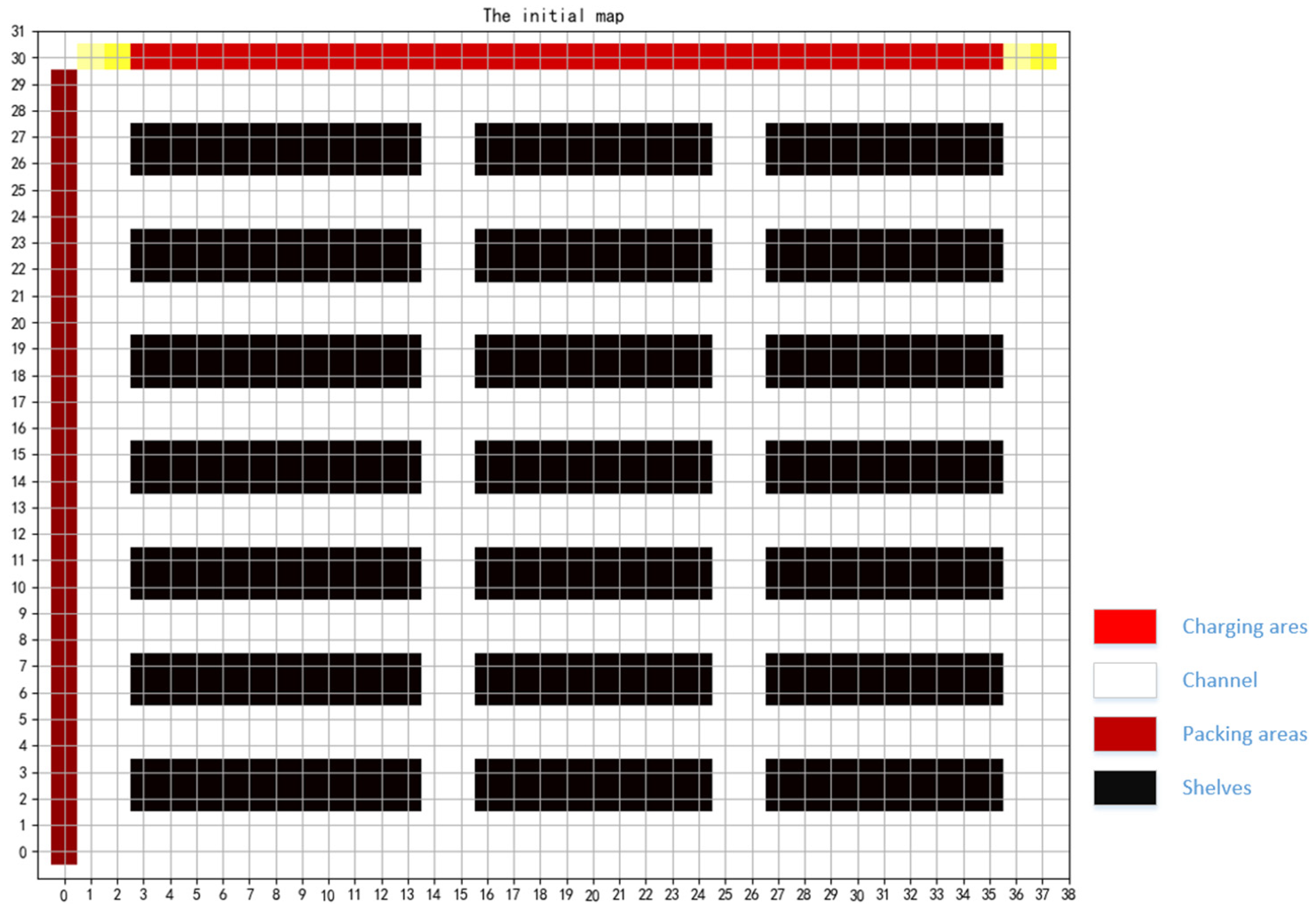
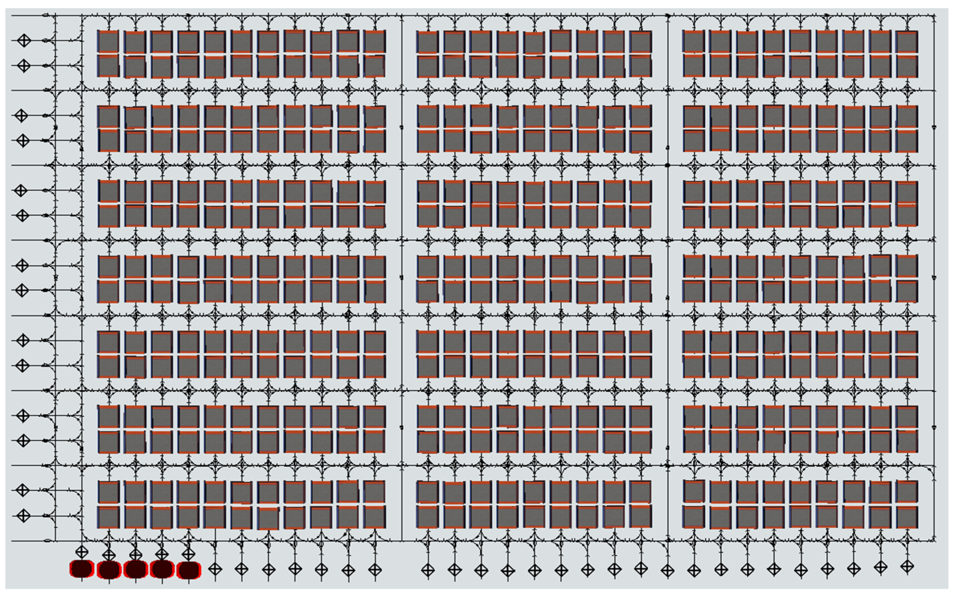
The intelligent warehouse model represented by a grid is adopted. The model’s environment is flexible and reconfigurable, as depicted in
Figure 1. The grid map is divided into four sections:
- (1)
The packing area, denoted as (i.e., ), is situated on the left-hand side of the map. Each packing station is staffed with a dedicated worker for efficient packaging operations.
- (2)
The bidirectional channel consists of two adjacent rows or columns, while the single row or column channel only permits unidirectional traffic. Each AGV is required to adhere to the traffic rule of ’move on the right’.
- (3)
The shelf area comprises individual shelves (i.e., , where is the number of shelves), which can be moved independently and are transported to the packing station by AGVs. Once the packing task is completed, the AGV delivers the shelf to its nearest available location within a vacant shelf area. In absence of new orders, the AGV remains stationary directly beneath its assigned shelf.
- (4)
The charging area, denoted as (i.e., ), is situated at the topmost part of the map. The AGV is obligated to return to the designated charging area once its battery level falls below 20%.
2.1. Working Characteristics of AGVs
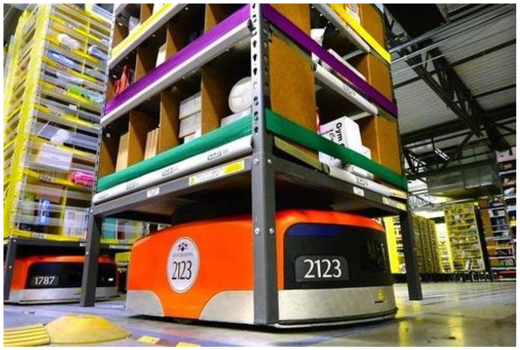
As illustrated in
Figure 2, a fleet of AGVs denoted by
, where
represents the number of AGVs, are efficiently transporting shelves within the warehouse at a constant velocity
v. Upon receiving task instructions, each AGV is capable of autonomously devising its own optimal route based on an individualized map, which is tailored to its unique starting and ending locations.
2.2. Centralized and Distributed Control Process
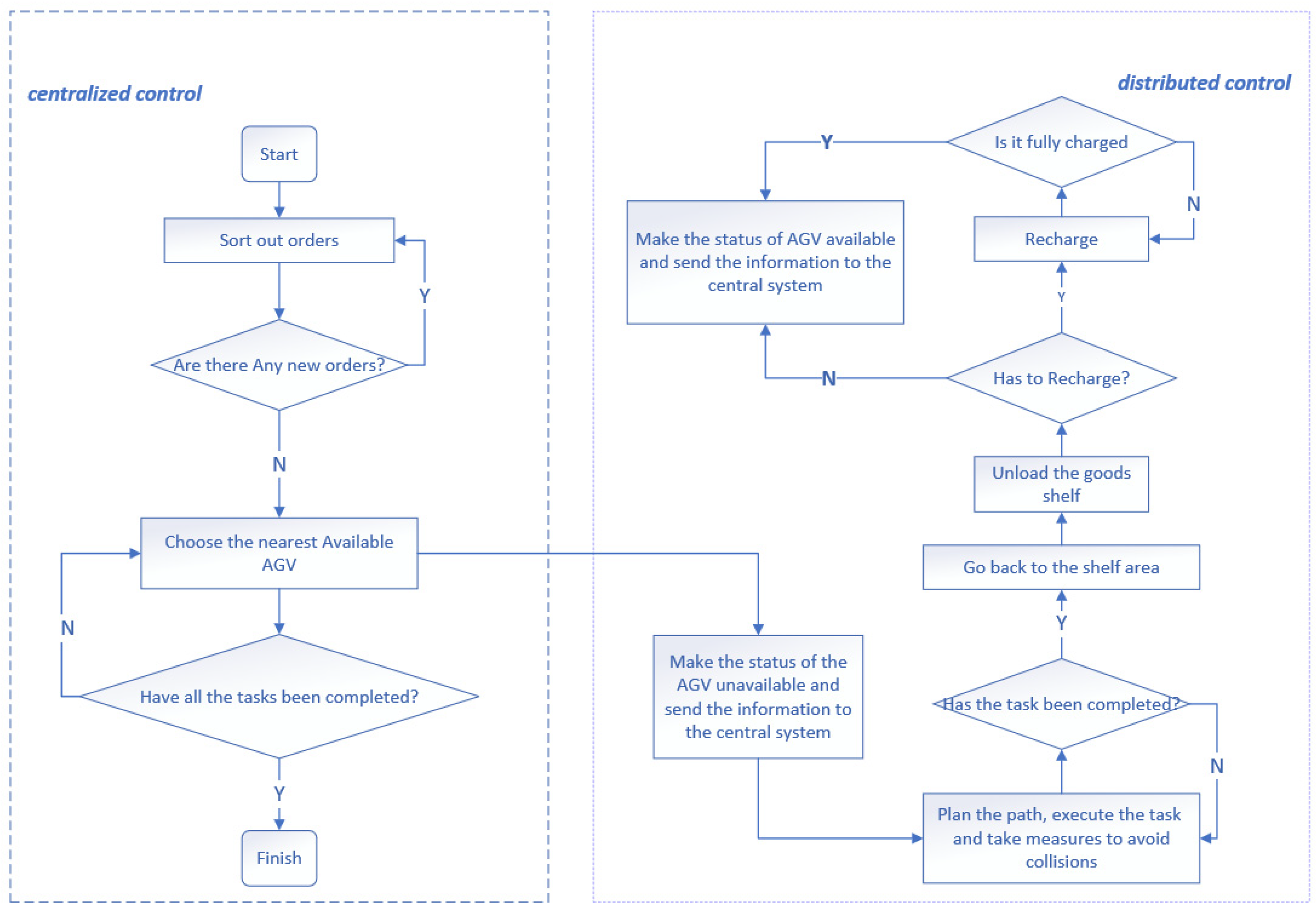
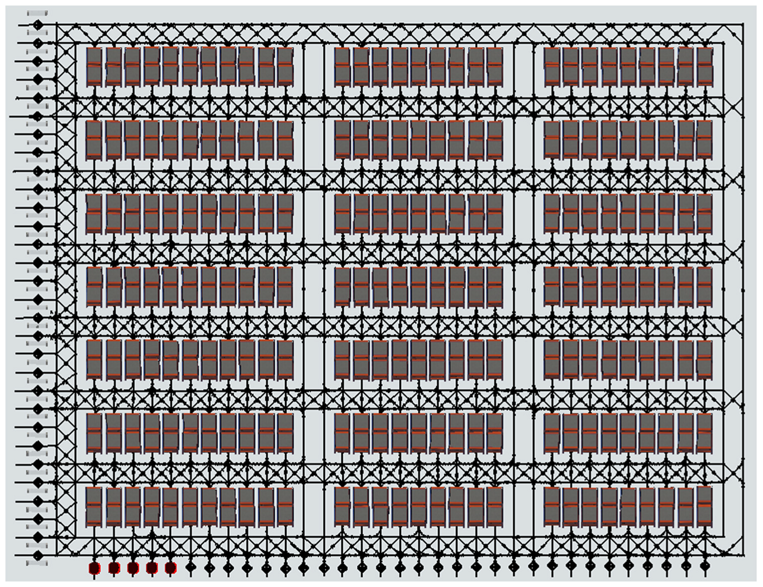
The proposed centralized and distributed control process for intelligent warehouse is illustrated in
Figure 3.
Initially, the central processing system categorizes orders based on their time, location, type and other relevant information. Since this paper focuses primarily on bidirectional channel-based multi-AGV route planning methods, the orders are sorted according to the distance between the multi-AGV and target shelf. The central control system maintains and updates all location and status information. The order information will be transmitted to the central system in real time, containing details of the goods and their corresponding shelves. The central control system will calculate the distance between these shelves and all available AGVs before dispatching orders to the nearest idle AGV. Subsequently, the status of the assigned AGV becomes unavailable.
Then, the AGV plans its path and directly reaches the designated shelf location. At this point, the central control system transmits information regarding the nearest available picking station to the AGV while simultaneously updating the status of the packing station to ‘unavailable’. Once the AGV departs, the shelf station’s status returns to ‘available’. Once the AGV plans the path and completes the unloading, the status of the picking station becomes ‘available’. The central control system will transmit the location information of the nearest available shelf station to the AGV.
Once the AGV delivers the shelf to its destination, the corresponding shelf station will become ‘unavailable’. However, if an AGV has to meet certain conditions before charging, this may cause stagnation in warehouse logistics. If all AGVs operate simultaneously after being fully charged, they will reach the charging condition at roughly the same time due to their similar working time and power consumption speed. The aforementioned issue may arise when simultaneous charging occurs; hence, it is imperative to have multiple AGVs with the highest power capacity continue operations to prevent order backlog. Meanwhile, the remaining AGVs should return to the charging station upon task completion. The number of operational AGVs can be adjusted based on order generation speed.
The central control system discussed in this paper fulfills several key functions. First, it is responsible for storing and updating the location and status information of all devices. For instance, order information containing details about the goods and their corresponding shelves will be transmitted to the central control system. Second, the central control system will compute the distance between corresponding shelves and all available AGVs, subsequently dispatching orders to the nearest idle AGV in proximity to the said shelf. Third, the AGV plans its path and directly reaches the designated shelf location. At this point, the central control system transmits information regarding the nearest available picking station to the AGV. Upon departure of the AGV, the status of the shelf station will become ‘available’. Finally, once the AGV plans its path and completes the unloading process, the central control system will transmit the location information of the nearest available shelf station to the AGV.
3. Dynamic Map Design
The current research on multi-AGV route planning within warehouses predominantly employs unidirectional channels. While these channels may seem advantageous for space conservation purposes, their drawbacks are equally evident. For instance, as shown in
Figure 4, when facing Situation A, AGV_1 will not remain stationary but instead execute a right turn directly based on the mathematical model of collision avoidance due to its prior arrival at the intersection. Consequently, deadlock inevitably occurs. In Situation B, congestion arises because AGV_1 has to wait for AGV_2 to enter the shelf area before proceeding, resulting in the immobilization of AGV_3–6 and significantly compromising transport efficiency.
Zhang (2018) [
31] proposed a dynamic weighted map to indicate the level of congestion on each road, which enabled the route planner to avoid congested channels. However, this may result in suboptimal routes. When AGVs encounter highly congested destination areas, blockages and deadlocks are still likely to occur. To address this issue, this paper draws inspiration from real-world traffic and employs bidirectional channels for planning routes for multiple AGVs. However, previous research has shown that the implementation of the ‘move on the right’ rule presents a challenge for the A* algorithm, as it cannot automatically select the appropriate channel for AGVs. To address this issue, this paper proposes a solution based on dynamic maps. With this approach, each AGV will have its own independent map, which is dynamically updated to ensure compliance with traffic rules. According to the starting and ending points of AGVs, the algorithm dynamically sets up obstacles in the left channel of potential routes and utilizes the updated map as an input for route-planning algorithms to obtain optimal routes. The specific methodology is presented as follows:
- (1)
Divide the map into different regions
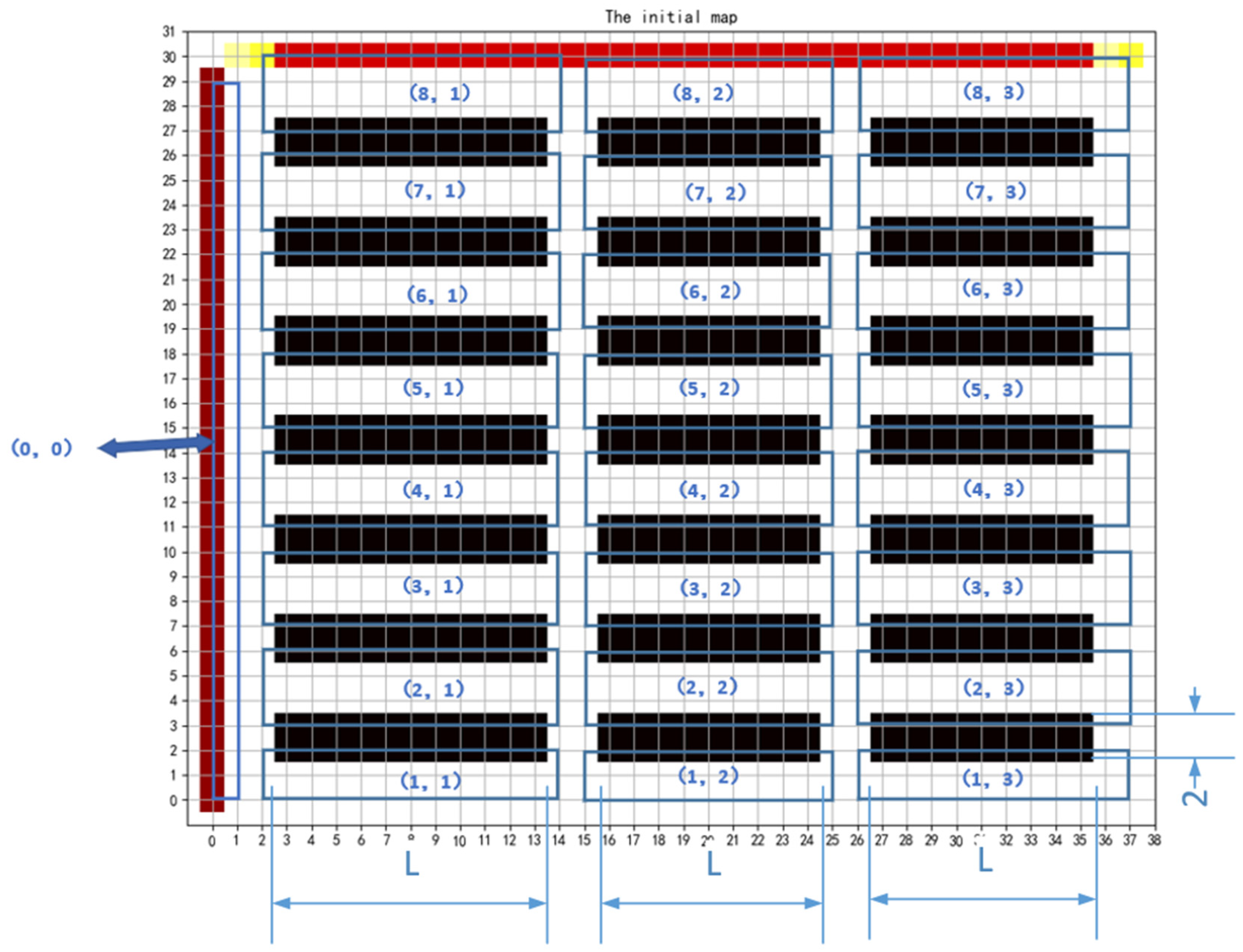
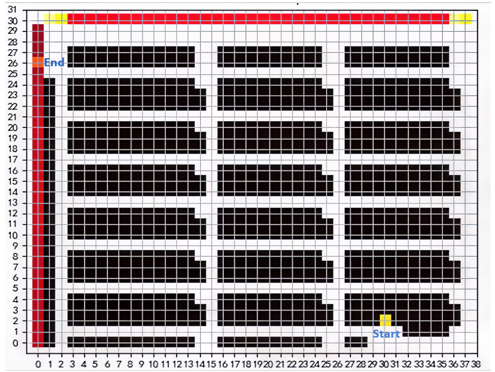
According to the allocation of the shelf and packing areas, the entire warehouse is divided into multiple regular sub-areas, as shown in
Figure 5. Each shelf area comprises several shelving stations with a size of 2*
L. The sub-area is identified by its sequence number (
m, n), where
m represents the row number, and
n represents the column number. The location of the packing area is designated as (0,0). It is noted that generalizations facilitate the modeling of a real warehouse, while
Figure 5 serves to illustrate its operations and is exemplified by the inclusion of two numbers (29,38) to delineate the scope of the warehouse.
- (2)
The basic rules of changing the map
The modification of the map should take into account three factors: the starting point, ending point and middle area. As AGVs strictly adhere to the traffic rule of ‘move on the right’, the left channels must be designated as obstacles. Assuming that the coordinate of the starting point is (
x1, y1), then the sub-area sequence number for the starting point is (
m1, n1). The set of new obstacle coordinates in the starting area can be obtained by Algorithm 1.
| Algorithm 1. The set of new obstacle coordinates in the starting area |
| Input:
(x1, y1),(m1, n1)
|
| Output:
map[a: b, c: d] = x |
| 1: | if n1 = 0 then |
| 2: | map[(y1 + 1):29,1] = 0 |
| 3: | map[0:(y1 − 1),2] = 0 |
| 4: | map[4k: (4k + 1), 2] = 1, k = 0, 1, 2, 3, 4, 5, 6, 7 |
| 5: | end if |
| 6: | if m1 = 1 and n1 ≠ 0 then |
| 7: | map[2:3, k(L + 1) + 1] = 0, k = 1, 2, 3 |
| 8: | map[0,3: (x1 − 1)] = 0 |
| 9: | map[1,(x1 + 1):35] = 0 |
| 10: | map[1,k(L + 1) + 1 : k(L + 1) + 2] = 1, k = 1, 2 |
| 11: | end if |
| 12: | if 2 ≤ m1 ≤ 7 and n1 ≠ 0 then |
| 13: | row = 2 + (m1 − 2)*4 |
| 14: | map[row: (row + 1),2 + k(L + 1)] = 0, k = 0, 1, 2, 3 |
| 15: | map[(row + 4): (row + 5), k(L + 1) + 1] = 0, k = 1, 2, 3 |
| 16: | map[(row + 2),3: (x1 − 1)]] = 0 |
| 17: | map[(row + 3), (x1 + 1):35]] = 0 |
| 18: | map[(row + q), k(L + 1) + 1: k(L + 1) +2] = 1, k = 1, 2; q = 2, 3 |
| 19: | end if |
| 20: | if m1 = 8 and n1 ≠ 0 then |
| 21: | map[26:27, k(L + 1) + 2] = 0, k = 0, 1, 2, 3 |
| 22: | map[28,3: (x1 − 1)] = 0 |
| 23: | map[29, (x1 + 1): 35] = 0 |
| 24: | map[28, k(L + 1) + 1: k(L + 1) + 2] = 1, k = 1, 2 |
| 25: | end if |
| 26: | return map[a: b, c: d] = x |
Note: map[a: b, c: d] = x indicates the assignment of rows from a to b and columns from c to d in the map to x. Obstacles are represented by 0, while channels are represented by 1.
Assuming that the coordinate of the ending point is (
x2,
y2), the sub-area sequence number for the ending point can be represented as (
m2,
n2). The set of new obstacle coordinates in the ending area can be obtained by Algorithm 2.
| Algorithm 2. The set of new obstacle coordinates in the ending area |
| Input:
(x1, y1),(m1, n1)
|
| Output:
map[a: b, c: d] = x |
| 1: | if n2 = 0 then |
| 2: | map[(y2 + 1):29,2] = 0 |
| 3: | map[0: (y2 − 1),1] = 0 |
| 4: | map[4k: (4k + 1), 2] = 1, k = 0, 1, 2, 3, 4, 5, 6, 7 |
| 5: | end if |
| 6: | if m2 = 1 and n2 ≠ 0 then |
| 7: | map[2: 3, k(L + 1) + 2] = 0, k = 0, 1, 2, 3, |
| 8: | map[1,3: (x2 − 1)] = 0 |
| 9: | map[0,(x2 + 1):35] = 0 |
| 10: | map[1, k(L + 1) + 1 : k(L + 1) + 2] = 1, k = 1, 2 |
| 11: | end if |
| 12: | if 2 ≤ m2 ≤ 7 and n2 ≠ 0 then |
| 13: | row = 2 + (m2 − 2)*4 |
| 14: | map[row: (row + 1), k(L + 1) + 1] = 0, k = 1, 2, 3 |
| 15: | map[(row + 4): (row + 5),k(L + 1) + 2] = 0, k = 0, 1, 2, 3 |
| 16: | map[(row + 3),3: (x2 − 1)]] = 0 |
| 17: | map[(row + 2), (x2 + 1):35]] = 0 |
| 18: | map[(row + q), k(L + 1) + 1: k(L + 1) + 2] = 1, k = 1, 2; q = 2, 3 |
| 19: | end if |
| 20: | if m2 = 8 and n2 ≠ 0 then |
| 21: | map[26: 27, k(L + 1) + 1] = 0, k = 1, 2, 3 |
| 22: | map[29,3: (x2 − 1)] = 0 |
| 23: | map[28,(x2 + 1):35] = 0 |
| 24: | map[28, k(L + 1) + 1: k(L + 1) + 2] = 1, k = 1, 2 |
| 25: | end if |
| 26: | return map[a: b, c: d] = x |
The obstacles within the middle area can be strategically positioned in relation to the established starting and ending points as Algorithms 3-1–3-4.
| Algorithm 3-1. The set of new obstacle coordinates the middle area |
| Input:
(m1, n1)
|
| Output:
map[a: b, c: d] = x |
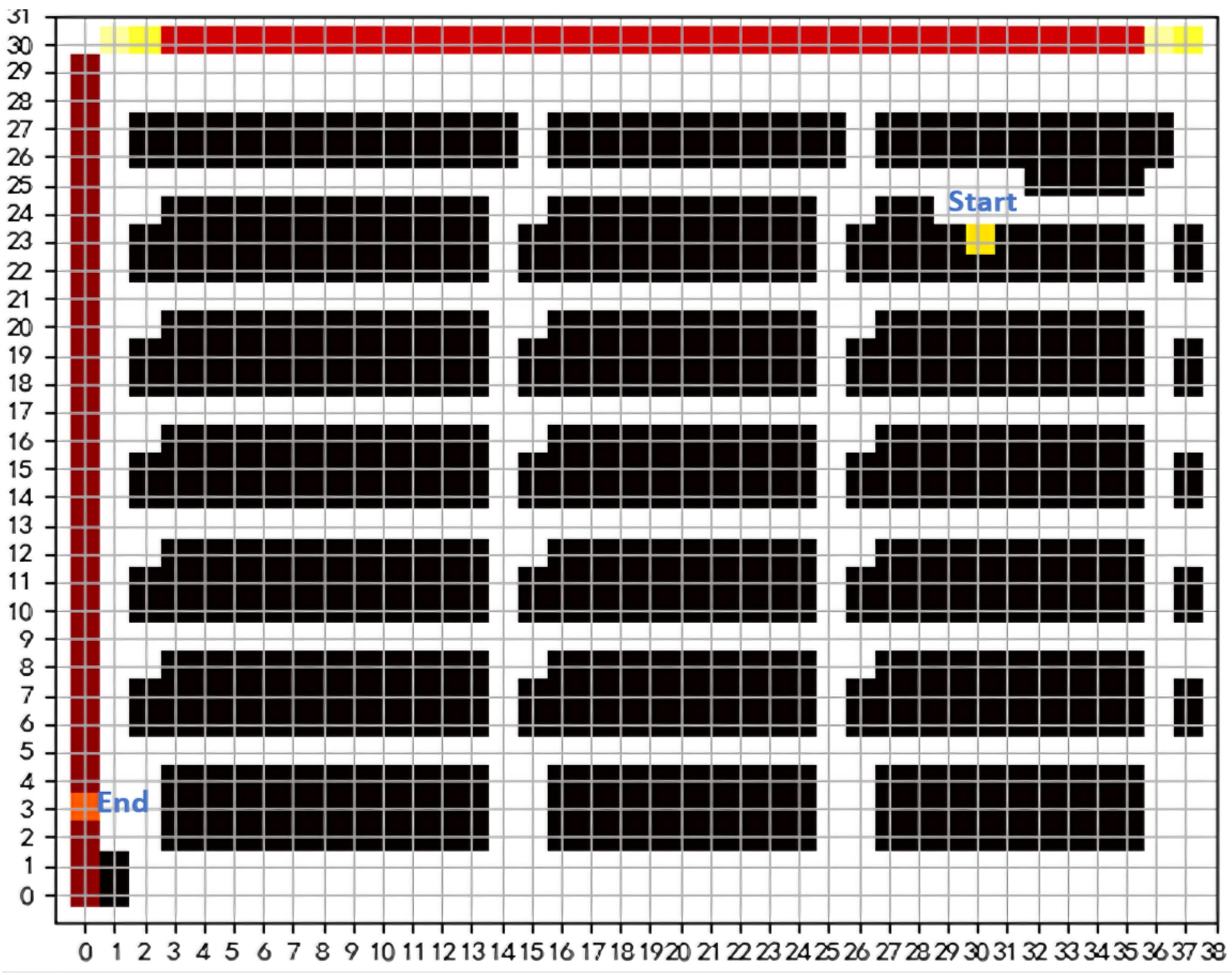
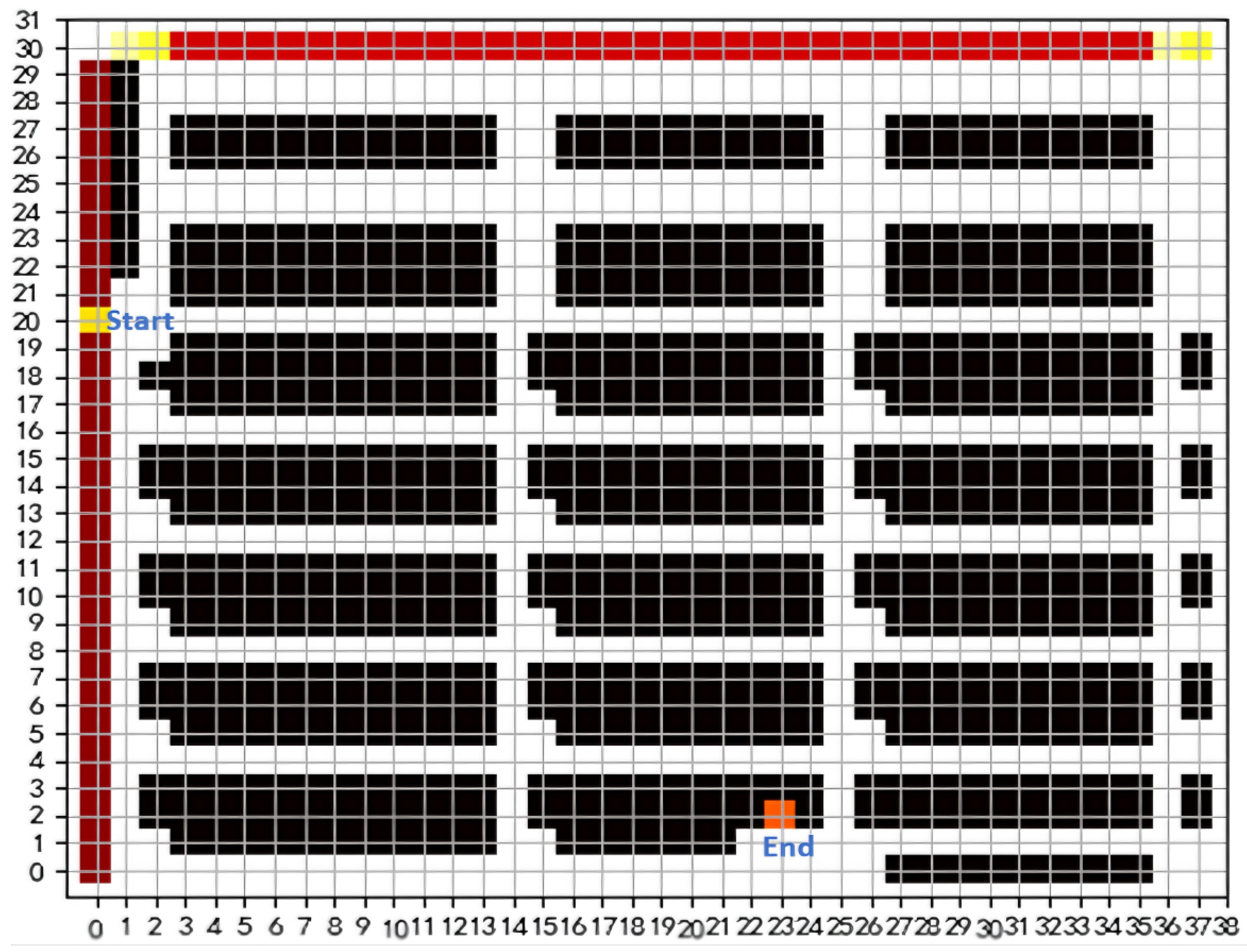
| 1: | if n2 < n1 and m2 > m1 (The end point is at the top left of the start point, as seen in Figure 6) then |
| 2: | if n2 ≠ 0 then |
| 3: | for each i ∈ [m1 + 1 , m2 − 1] do |
| 4: | a = 4*(i − 1) |
| 5: | map[a,3 + k(L + 2): 3 + k(L + 2) + (L − 1)] = 0, k = 0, 1, 2 |
| 6: | map[(a − 2): (a − 1), k(L + 1) + 1] = 0, k = 1, 2, 3 |
| 7: | end for |
| 8: | else if n2 = 0 then |
| 9: | for each i ∈ [m1 + 1 , m2] do |
| 10: | a = 4*(i − 1) |
| 11: | map[a, 3 + k(L + 2): 3 + k(L + 2) + (L − 1)] = 0, k = 0, 1, 2 |
| 12: | map[(a − 2): (a − 1), k(L + 1) + 1] = 0, k = 1, 2, 3 |
| 13: | end for |
| 14: | end if |
| 15: | end if |
| 16: | return map[a: b, c: d] = x |
| Algorithm 3-2. The set of new obstacle coordinates the middle area |
| Input:
(m1, n1)
|
| Output:
map[a: b, c: d] = x |
| 1: | if n2 < n1 and m2 < m1 (The end point is at the bottom left of the start point, as seen in Figure 7) then |
| 2: | if n2 ≠ 0 then |
| 3: | for each i ∈ [m2 + 1, m1 − 1] do |
| 4: | a = 4*(i − 1) |
| 5: | map[a,3 + k(L + 2): 3 + k(L + 2) + (L − 1)] = 0, k = 0, 1, 2 |
| 6: | map[(a + 2): (a + 3), k(L + 1) + 2] = 0, k = 1, 2, 3 |
| 7: | end for |
| 8: | else if n2 = 0 then |
| 9: | for each i ∈ [m2, m1 − 1] do |
| 10: | a = 4*(i − 1) |
| 11: | map[a, 3 + k(L + 2): 3 + k(L + 2) + (L − 1)] = 0, k = 0, 1, 2 |
| 12: | map[(a + 2): (a + 3), k(L + 1) + 2] = 0, k = 0, 1, 2, 3 |
| 13: | end for |
| 14: | end if |
| 15: | end if |
| 16: | return map[a: b, c: d] = x |
| Algorithm 3-3. The set of new obstacle coordinates the middle area |
| Input:
(m1, n1)
|
| Output:
map[a: b, c: d] = x |
| 1: | if n2 > n1 and m2 > m1 (The end point is at the top right of the start point, as seen in Figure 8) then |
| 2: | if n1 ≠ 0 then |
| 3: | for each i ∈ [m1 + 1, m2 − 1] do |
| 4: | a = 4*(i − 1) + 1 |
| 5: | map[a, 3 + k(L + 2): 3 + k(L + 2) + (L − 1)] = 0, k = 0, 1, 2 |
| 6: | map[(a + 1): (a + 2), k(L + 1) + 1] = 0, k = 1, 2, 3 |
| 7: |
end for |
| 8: | else if n1 = 0 then |
| 9: | for each i ∈ [m1, m2 − 1] do |
| 10: | a = 4*(i − 1) + 1 |
| 11: | map[a, 3 + k(L + 2): 3 + k(L + 2) + (L − 1)] = 0, k = 0, 1, 2 |
| 12: | map[(a + 1): (a + 2), k(L + 1) + 1] = 0, k = 1, 2, 3 |
| 13: |
end for |
| 14: |
end if |
| 15: | end if |
| 16: | return map[a: b, c: d] = x |
| Algorithm 3-4. The set of new obstacle coordinates the middle area |
| Input:
(m1, n1)
|
| Output:
map[a: b, c: d] = x |
| 1: | if n2 > n1 and m2 < m1 (The end point is at the bottom right of the start point, as seen in Figure 9) then |
| 2: | if n1 ≠ 0 then |
| 3: | for each i ∈ [m2 + 1, m1 − 1] do |
| 4: | a = 4*(i − 1) + 1 |
| 5: | map[a, 3 + k(L + 2): 3 + k(L + 2) + (L − 1)] = 0, k = 0, 1, 2 |
| 6: | map[(a − 3): (a − 2), k(L + 1) + 2] = 0, k = 1, 2, 3 |
| 7: | end for |
| 8: | else if n1 = 0 then |
| 9: | for each i ∈ [m2 + 1, m1] do |
| 10: | a = 4*(i − 1) + 1 |
| 11: | map[a, 3 + k(L + 2): 3 + k(L + 2) + (L − 1)] = 0, k = 0, 1, 2 |
| 12: | map[(a − 3): (a − 2), k(L + 1) + 2] = 0, k = 1, 2, 3 |
| 13: | end for |
| 14: | end if |
| 15: | end if |
| 16: | return map[a: b, c: d] = x |
4. Route Planning
The A* algorithm is widely recognized as a best first heuristic algorithm, specifically designed for identifying optimal routes in grid environments. However, the conventional A* algorithm relies on static maps and primarily focuses on planning relatively short routes based solely on this information. As a result, it is only applicable to intelligent warehouses with unidirectional channels, where AGVs are mandated to exclusively move along the right-hand side (i.e., AGVs cannot meet the rule of ‘move on the right’). Additionally, the conventional A* algorithm solely accounts for route cost and disregards AGV travel time. Therefore, this paper proposes a dynamic map alteration algorithm based on the A* algorithm to enable the alteration of bidirectional channels in intelligent warehouses.
The proposed algorithm involves the following main steps:
- (1)
Create two point sets: open list and close list. The open list is utilized to store potential route points, while the close list is used for those, which cannot be considered as such.
- (2)
Search for eight adjacent grids surrounding the current grid.
- (3)
Evaluate each grid. If the grid lies within the channel area and has not been added to either list, then its route cost would be estimated.
- (4)
Choose the grid with the lowest value in the open list as the current point, and designate it as the parent node of the previous point before moving it to the close list.
- (5)
Repeat steps (2)–(4) until the current point becomes the end point.
- (6)
Starting from the end point, trace back each point’s parent node until arriving at the start point to obtain a satisfactory route.
The process for calculating the route cost
is presented as
In Equation (1),
represents the actual cost of traversing from the starting point to grid
, given as
where
denotes the velocity of AGV, and
denotes the actual distance from the (
n − 1)th grid to the
nth grid. In general,
equals 1 when the
nth grid is located horizontally or vertically to the (
n − 1)th grid, and
equals 1.4 when the
nth grid is positioned diagonally to the (
n − 1)th grid.
In Equation (1),
is a heuristic function, representing the estimated cost of traveling from the current grid to the target grid, given as
where
is the Manhattan distance from the current grid to the target grid, presented as
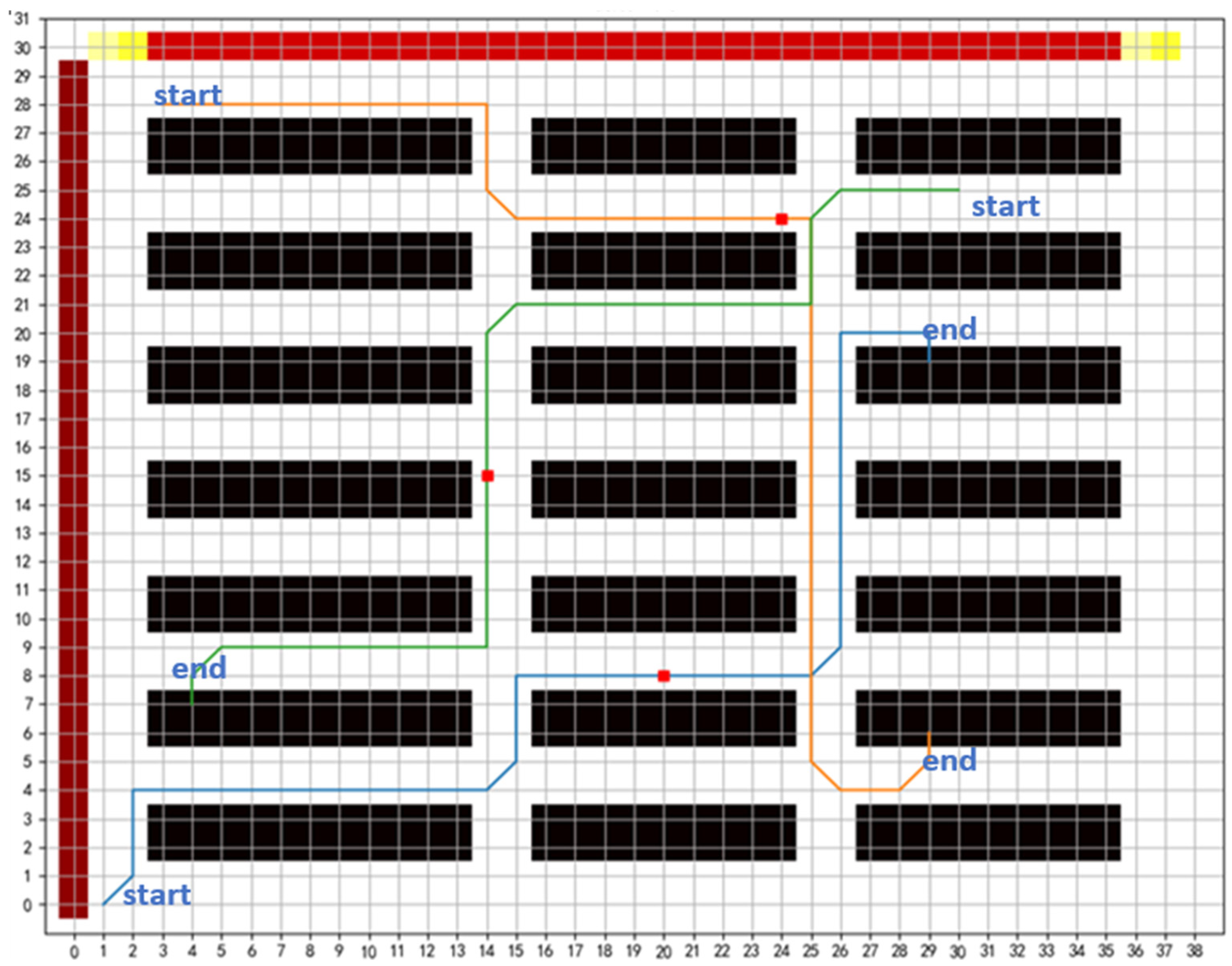
As an illustration, three AGVs are concurrently in motion, and their respective travel paths are depicted in
Figure 10.
5. Collision Avoidance
As the proposed method only allows for individual route planning of each AGV, collisions and deadlocks remain significant challenges in multi-AGV scheduling problems. Compared to unidirectional channel-based intelligent warehouses, bidirectional channel-based ones present a wider range of collision scenarios. This paper classifies collisions based on different road conditions and provides corresponding avoidance strategies accordingly.
To ensure collision avoidance, AGVs must establish communication and share their operational status with other AGVs, which may pose a conflict. By doing so, each AGV can integrate its own state with those of the surrounding AGVs and apply appropriate avoidance rules to take reasonable actions.
5.1. Collision Classification
- (1)
Collisions in crossroad
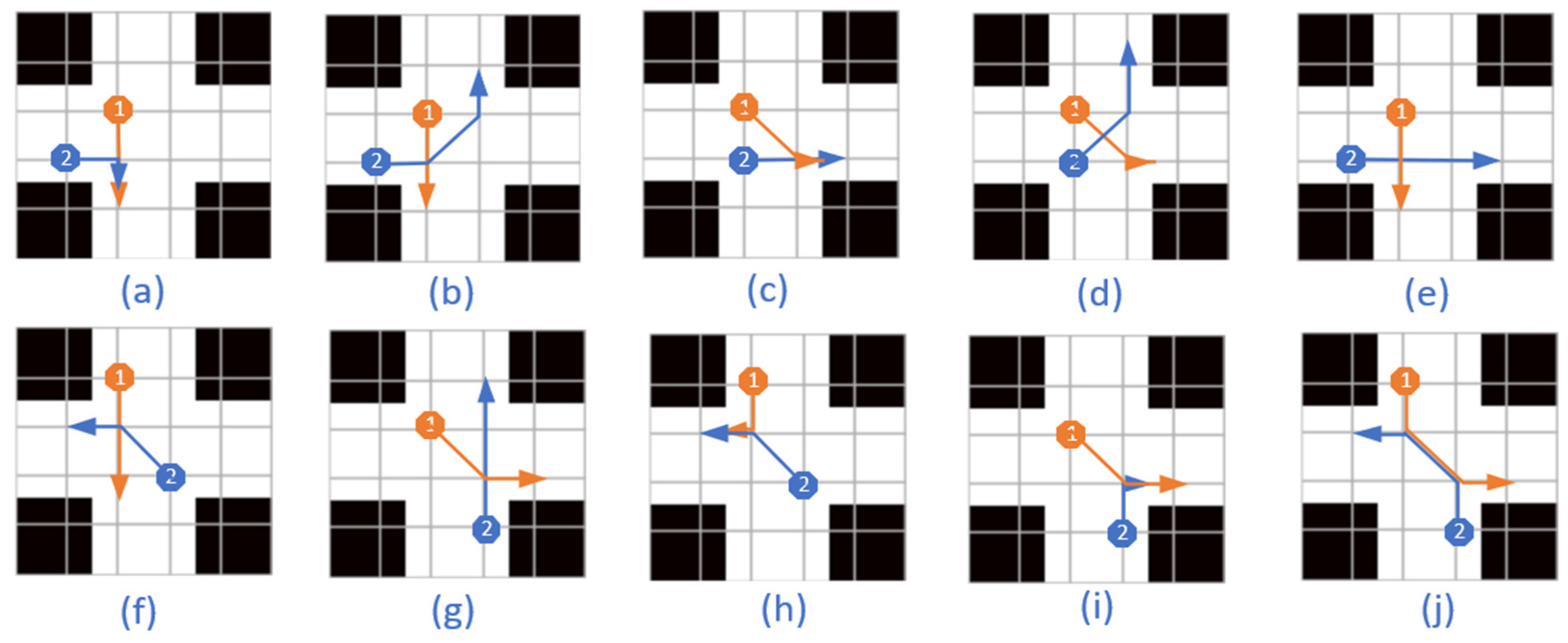
When two vehicles cross a junction simultaneously, they are susceptible to collisions. As illustrated in
Figure 11, there exist 10 distinct collision scenarios. In cases (a)–(e), two AGVs approach from mutually perpendicular channels, while in cases (f)–(j), two AGVs approach from parallel but opposing channels. In case (j), collisions occur on the route between two nodes rather than at the nodes themselves. In all other scenarios, collisions occur directly at the nodes. When two AGVs approach a crossroad from opposite directions, their relative positions and collision scenarios remain consistent. Therefore, this paper only presents one representative case for each collision scenario in the analysis.
- (2)
Collisions in T-crossroad
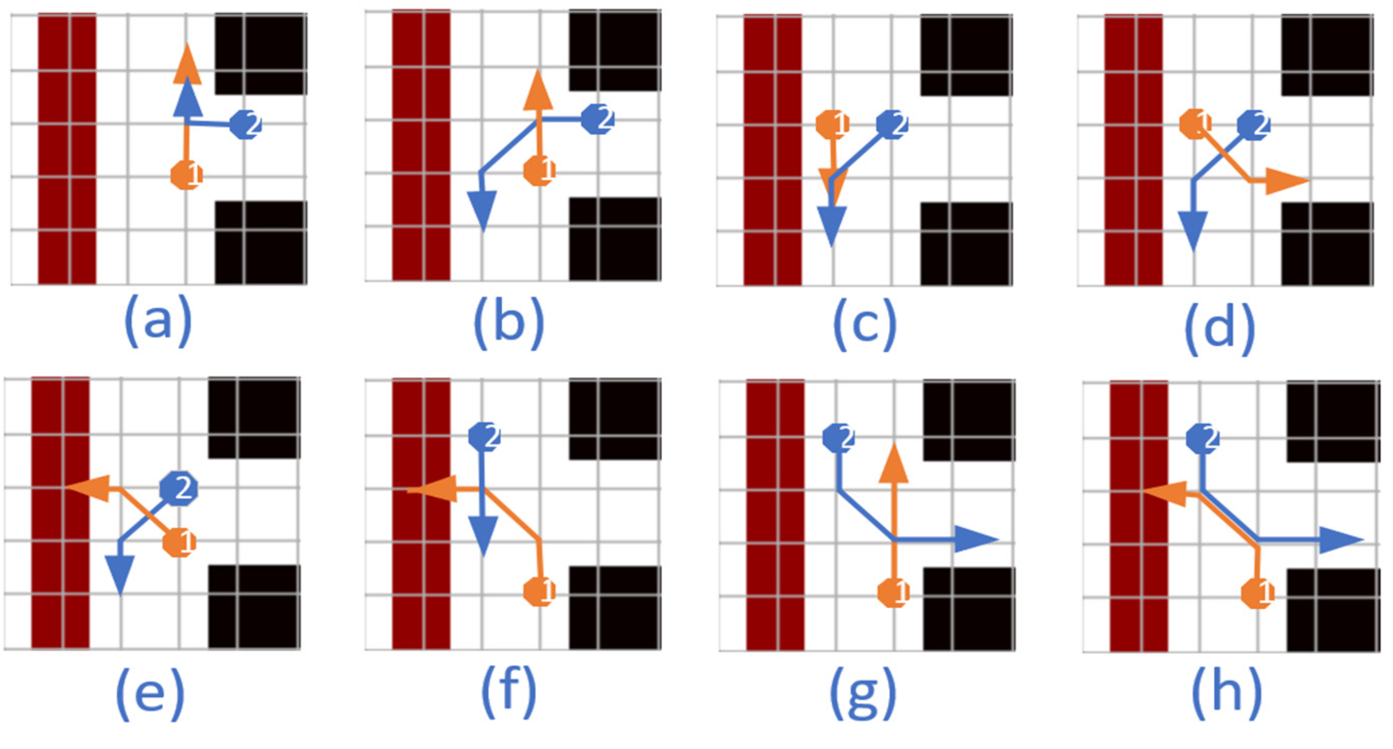
The T-crossroad is situated at the periphery of the warehouse, which also happens to be a high-risk zone for collisions. As depicted in
Figure 12, there exist eight distinct collision scenarios. In cases (a)–(e), two AGVs approach from the transverse and longitudinal channel, respectively, while in cases (f)–(h), both AGVs approach from the longitudinal channel. In cases (a)–(c) and (f)–(g), one AGV proceeds straight while the other turns; in cases (d)–(e) and (h), both AGVs turn. The T-crossroad depicted in
Figure 12 is situated on the leftmost edge of the warehouse. As the collision patterns at T-crossroads located on different edges are identical, this paper only presents one case for collision analysis.
- (3)
Collisions in bidirectional channel
Under normal circumstances, bidirectional channels do not result in collisions. However, when an AGV returns to the channels from a non-channel area (such as charging, packing or shelf areas) or needs to traverse reverse channels into non-channel areas on the opposite side, conflicts may arise with AGVs moving along the corresponding channels. As illustrated in
Figure 13, there exist eight distinct collision scenarios. In cases (a)–(d), one AGV proceeds straight while the other turns; in cases (e)–(h), both AGVs turn. In cases (a)–(c) and (e)–(g), one AGV enters the channel from a non-channel area; in cases (d) and (h), at least one AGV enters a non-channel area from the channel. Given that the collision scenarios are identical across different non-channel areas, this paper solely analyzes bidirectional channels within shelf areas.
5.2. Collision Detection
The following symbols are quoted for the purpose of providing a clear explanation.
- (1)
denotes the coordinate of a node with sequence number m in the route of the AGVn. It should be noted that the same node may have different serial numbers for different AGVs. For example, if node x exists both in the route of AGV1 and AGV2, its sequence number in the route of AGV1 is , while its sequence number in the route of AGV2 is . Hence, for AGV1, the coordinate of node x is ; for AGV2, the coordinate of node x is . Notably, equals to in this scenario. Moreover, denotes the next node after the target node with sequence number α on the route of AGV1, while represents its preceding node.
- (2)
represents the arrival time of AGVn at the node with sequence number in its route.
- (3)
represents the processing time required for AGVn on the node with sequence number in its route.
In this paper, collisions are detected across three distinct road conditions, presented as follows.
- (a)
In
Figure 11, the collisions in cases (a)–(c) and (e)–(i) occur on the nodes. These collisions will occur if conditions (5)–(6) are met.
where
represents the time window for collision. The value of
is dependent on the velocity and size of the AGV, as well as the angle between their respective velocity directions.
The collision in case (j) occurs between two nodes. The route points with sequence numbers
and
+ 1 of the
AGV1 correspond to those with sequence numbers
and
of the
AGV2. If conditions (7)–(9) are satisfied, the collision in case (j) will occur.
The collision in case (d) occurs between two nodes. The route points with sequence numbers
and
+ 1 of the
AGV1 do not correspond to the route points with sequence numbers
and
of the
AGV2. If conditions (10)–(11) are satisfied, the collision in case (d) will occur.
- (b)
In
Figure 12, the collisions in cases (a)–(c) and (f)–(g) occur at the nodes. If the above Equations (5) and (6) are satisfied, the collisions in cases (a)–(c) and (f)–(g) will occur. The collisions in cases (d)–(e) occur between two nodes. The route points with sequence numbers
and
+ 1 of the AGV1 do not correspond to the route points with sequence numbers
and
of the AGV2. If the above Equations (10) and (11) are satisfied, the collisions in cases (d)–(e) will occur. The collision in case (h) occurs between two nodes. The route points with sequence numbers
and
+ 1 of the AGV1 correspond to the route points with sequence numbers
and
of the AGV2. If conditions (7)–(9) are satisfied, the collision in case (h) will occur.
- (c)
In
Figure 13, the collisions in cases (a)–(d) and (g) occur at the nodes. If the above Equations (5) and (6) are satisfied, the collisions in cases (a)–(c) and (g) will occur. The collisions in cases (e)–(f) occur between two nodes. The route points with sequence numbers
and
+ 1 of the AGV1 do not correspond to the route points with sequence numbers
and
of the AGV2. If the above Equations (10) and (11) are satisfied, the collisions in cases (e)–(f) will occur. The collision in case (h) occurs between two nodes. The route points with sequence numbers
and
+ 1 of the AGV1 correspond to the route points with sequence numbers
and
of the AGV2. If conditions (7)–(9) are satisfied, the collision in case (h) will occur.
5.3. Collision Solution Strategies
When a collision is detected, different collision avoidance strategies are adopted according to different road conditions. Thus, it is vital to determine the road conditions where the collisions occur.
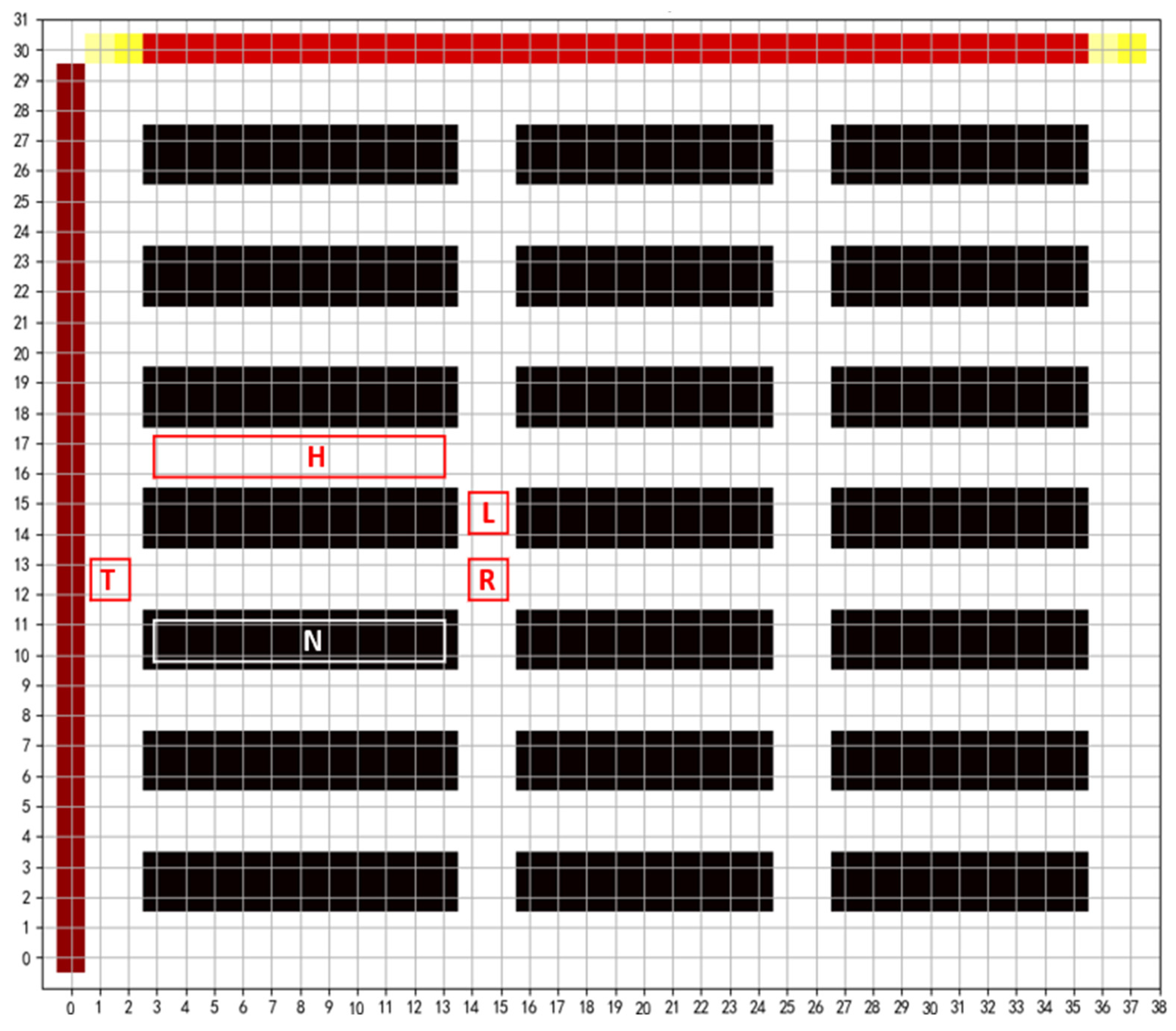
There are several coordinate sets introduced, as seen in
Figure 14, given as follows:
- (1)
R represents the coordinate collection of the crossroads;
- (2)
T represents the coordinate set of the T-crossroads;
- (3)
N represents the coordinate set of the non-channel areas, including the shelf area, the packing area and the charging area;
- (4)
H represents horizontal channels, excluding the area of crossroads and T-crossroads;
- (5)
L represents the longitudinal channels, excluding the area of crossroads and T-crossroads.
For the collision avoidance strategy under three road conditions, due to the poor continuity of the longitudinal channel, if three AGVs are waiting for the longitudinal channel in a row, the AGVs on the horizontal channel should go first; then, the AGVs on the next longitudinal channel have to wait, which means that this condition will conflict with the strategy itself. The contradiction between two strategies will inevitably lead to deadlock. Thus, when two AGVs come from the horizontal and longitudinal channels, respectively, the AGV priority strategy in the longitudinal channel is usually adopted.
- (1)
When a collision is detected and Equation (12) is satisfied, the collision in
Figure 11 occurs.
When Equation (13) is satisfied, this means that the two AGVs come from the horizontal and longitudinal channels, respectively. If AGV1 travels horizontally and AGV2 travels longitudinally, the strategy adopted in this case is as follows: If , then AGV1 waits at waypoint until AGV2 passes through the collision point; if , then AGV1 waits at waypoint until AGV2 passes through the collision point.
When Equation (14) is satisfied, this means that both AGVs are on the horizontal or longitudinal channel. The strategy adopted in this case is to compare the values of , . If > , the time for AGV2 to pass through the collision point is relatively short. Then, AGV1 waits at waypoint until AGV2 passes through the collision point.
- (2)
When a collision is detected and Equation (15) is satisfied, the collision in
Figure 12 occurs.
When Equation (16) is satisfied, this means that both AGVs are on the longitudinal channel. The strategy adopted in this case is to compare the value of , . If > , the time for AGV2 to pass through the collision point is relatively short. Then, AGV1 waits at waypoint until AGV2 passes through the collision point.
- (3)
When a collision is detected and Equation (17) is satisfied, the collision in
Figure 13 occurs.
When Equation (18) is satisfied, this means that one AGV is in the non-channel area, and the other is moving on the channel. If AGV1 is in the non-channel area, the strategy adopted in this case is as follows: AGV1 waits where it is until AGV2 passes through the collision point.
When Equation (14) is satisfied, this means that both AGVs are on the horizontal or longitudinal channel. The strategy adopted in this case is to compare the value of , . If > , the time for AGV2 to pass through the collision point is relatively short. Then, AGV1 waits at waypoint until AGV2 passes through the collision point.
