1. Introduction
Swept sources have been widely used in various interferometric sensing and imaging applications, such as optical frequency domain reflectometry (OFDR) sensors [
1] and swept-source optical coherence tomography (SS-OCT) images [
2,
3,
4]. The OFDR sensor has been used to detect the backscatter signal along a long length of optical fiber core as a laser beam from swept source is converted to an interferometric sensing signal as a function of wavelength [
1]. The SS-OCT is also based on the OFDR interferometric backscattering signal sensor, but a two-dimensional (2-D) or three-dimensional (3-D) tomography image can be constructed with a beam scanning method over the target space [
2,
4]. Since the characteristics of a swept source affect the systems performance, it is necessary to improve the swept source’s lasing performances including sweeping bandwidth, line width, repetition speed,
etc. The improved linearity of output wavenumber (k)
versus sweeping time is an especially important parameter because the optical interference fringe on the linearized wavenumber (k) scale is essential for the domain conversion process with fast Fourier transformation (FFT) in OFDR sensors and SS-OCT imaging applications [
5,
6,
7,
8].
Typically, most swept sources are related to mechanical tuning filter of the output wavelength selection, such as a fiber Fabry–Perot tunable filter (FFP-TF) [
9,
10], a polygon mirror scanner [
11], and a tunable micro electro mechanical system (MEMS) filter [
12]. Furthermore, it is known that the change in this output wavelength
versus time is linearly proportional to the wavelength-scale (λ), not the wavenumber-scale (k). At a slow repetition speed, these mechanical tuning filters can easily operate with an arbitrary drive function or programmed wavenumber-linearized function. However, at a high swept rate, these filters work with a sinusoidal drive function only at the resonance frequency of the mechanical tuning filter, which is affected by a distorted response on the linearized wavelength scale. When the sweeping time does not correspond to the wavenumber-scale, an additional process of resampling and recalibration is required for linearization from the wavelength to the wavenumber scale after the detection of an optical interference fringe over time [
5,
6,
7,
8,
9,
10].
To overcome the mechanical limitation of filters, we suggest a novel filter-less electro-optic swept source based on the active mode locking (AML) method [
13,
14,
15]. However, the proposed AML swept source is limited by the wavelength-linear sweep
versus time: The change in the output
versus time is not linearly proportional to the wavenumber scale [
15]. Regarding the electro-optic drive, high-speed wavenumber-linear sweeping can be successfully implemented by applying a programmed wavenumber-linear drive function that is a 4th-order polynomial equation with time. However, it is still inconvenient to use an arbitrary function generator (AFG) with the difficult-to-obtain drive function in a one-to-one comparison process of the wavenumber value and the offset voltage of the AFG [
15].
In this work, we implemented a linearly wavenumber-swept uni-directional fiber-ring laser based on an acousto-optic tunable filter (AOTF) for interferometric sensing and imaging applications. It has been known that the filtered AOTF has the physically linearized relation between the optical frequency and acoustic frequency [
16,
17]. It means that only a simple triangular drive function is needed to ensure a linearly sweeping wavenumber in the time domain, instead of a specially programmed drive function with respect to time [
18,
19,
20,
21,
22]. Moreover, the AOTF filter exhibits more attractive characteristics of accurate wavelength selection, high stability, and non-mechanical actuation [
19,
20]. We also demonstrate that the electro-optic operation of a swept source is useful to apply any types of drive function and to improve environmental stability, compared with FFP-TF. The acquired 2D-OCT images are compared in parallel by applying both sinusoidal and wavenumber-linear drive functions.
2. Principle and Experimental Setup
The wavenumber-linearity operation is an intrinsic characteristic of an AOTF because the transmitted wavelength of the filter is inversely proportional to the applied radio frequency (RF) frequency of acoustic wave. As the RF is applied to a tellurium dioxide (TeO
2) crystal by the bonded transducer, the acoustic waves pass through the crystal to produce periodic optical lattices like a Bragg diffraction. When light propagates in the crystal, it is diffracted by the travelling acoustic wave. A specific wavelength of light is selected by changing the applied RF, which is expressed as follows:
where Δ
n is the birefringence of the TeO
2 crystal, α is a complex parameter depending on the design of AOTF,
Va is the speed of ultrasound wave, and
fa is the applied RF.
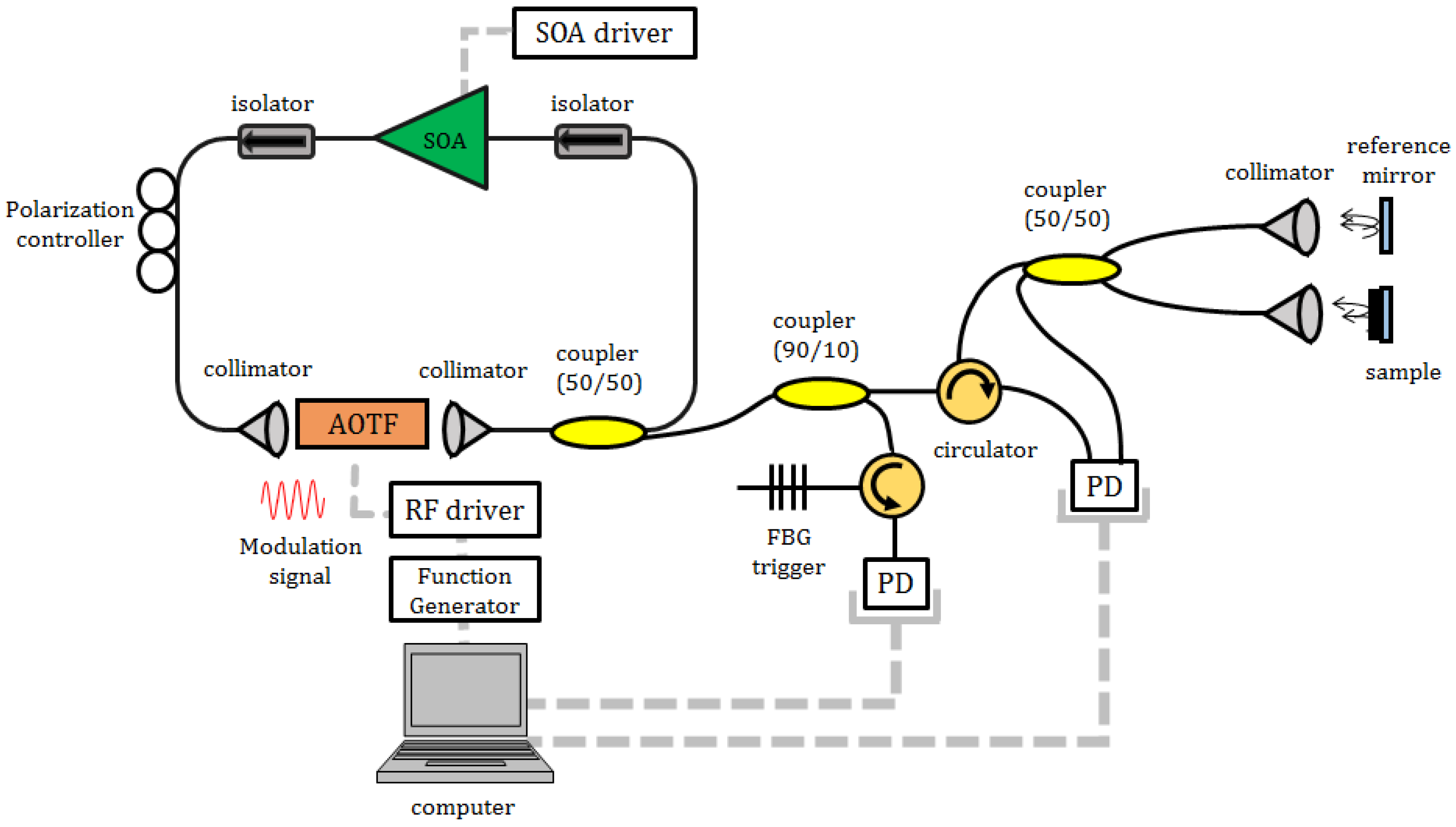
Figure 1 shows the experimental setup for the electro-optic swept source and SS-OCT interferometric imaging system. The swept source consists of a fiber-coupled semiconductor optical amplifier (SOA) as a gain medium, two isolators for a uni-directional propagation, an AOTF for selecting the lasing wavelength, a polarization controller (PC), and a 50:50 output coupler. The uni-directional ring configuration can support the improved stability and easy alignment in the laser cavity [
16,
17].
The SS-OCT imaging system is based on a fiber-type Michelson interferometer comprised of a broadband 50:50 coupler, a circulator, and a pair of reference mirror path and sample path. Objective lenses with 3× magnification and a 54 mm focal length were used to optimally gather sample images. A translation stage was used for a lateral scanning of the sample. A fiber Bragg grating (FBG) with a 1-nm bandwidth and an 840-nm center reflection is used to acquire a periodic trigger signal for the optical coherence tomography (OCT) imaging process. Since the center reflection wavelength of 840 nm is located within the bandwidth of the electro-optic swept source from 836.32 to 870.80 nm, one optical pulse clock for each A-scan can be periodically received at the photo detector (PD) through a 90/10 coupler and circulator. The reflecting intensities of the optical interference fringe were converted on a gray scale image along the transverse and axial distances. For the series of images, 1024 depth points were acquired to compose an image of 512 (axial) pixels × 256 (transverse) pixels.
3. Experimental Results
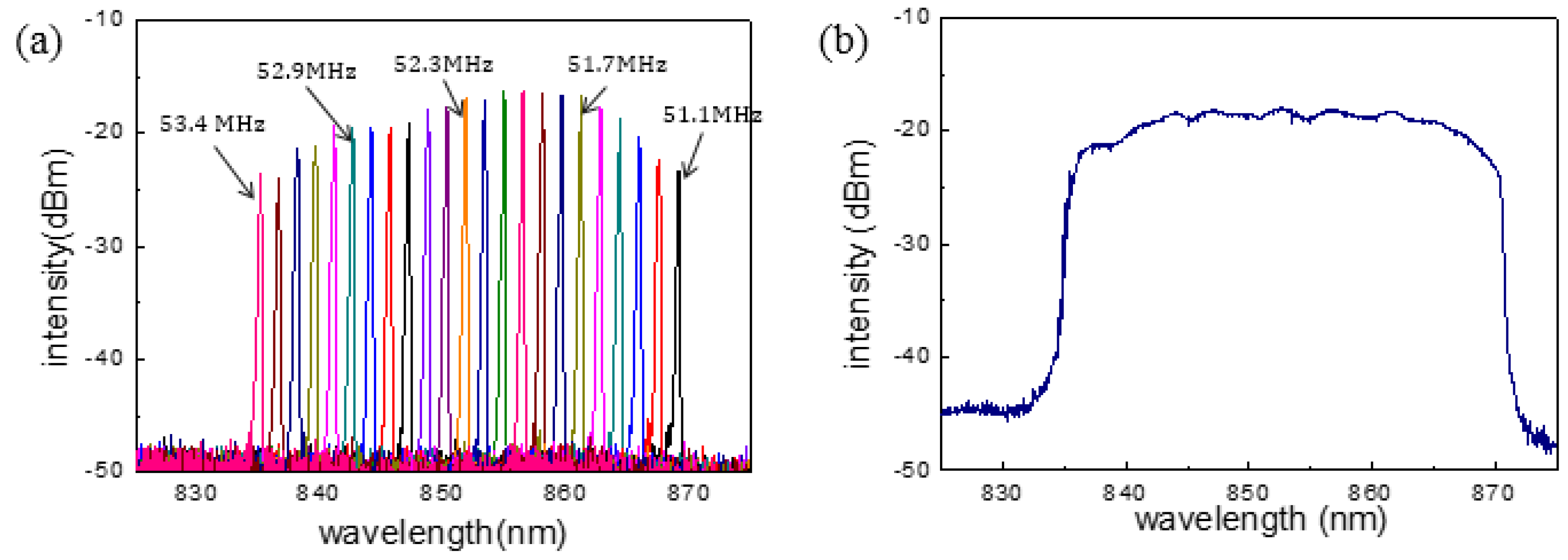
Figure 2a shows the static output spectra of the electro-optic swept source for applied RFs around the 52-MHz region. As the RF into the AOTF was varied from 51.1 to 53.4 MHz, the output lasing wavelength was shifted from 836.32 to 870.80 nm. The peak hold mode spectrum of the sweeping output was also measured in
Figure 2b to show 34.48 nm of the 20-dB band width. It is clear that this laser performance of the swept source is suitable for OFDR sensing and OCT imaging applications around the 850-nm region. Since the finite time response of the AOTF and the long round trip time of the laser cavity limit the output power and the bandwidth of the electro-optic swept source, the optical output characteristics begin to degrade upon sweeping within the entire bandwidth at the frequency above the kHz order for both sinusoidal and triangular drive functions [
17]. In comparison, we have also monitored that the conventional swept source with FFP-TF exhibits a decreased output power and distorted spectral shape at the sweeping rate below 1 kHz with the sinusoidal drive function [
10].
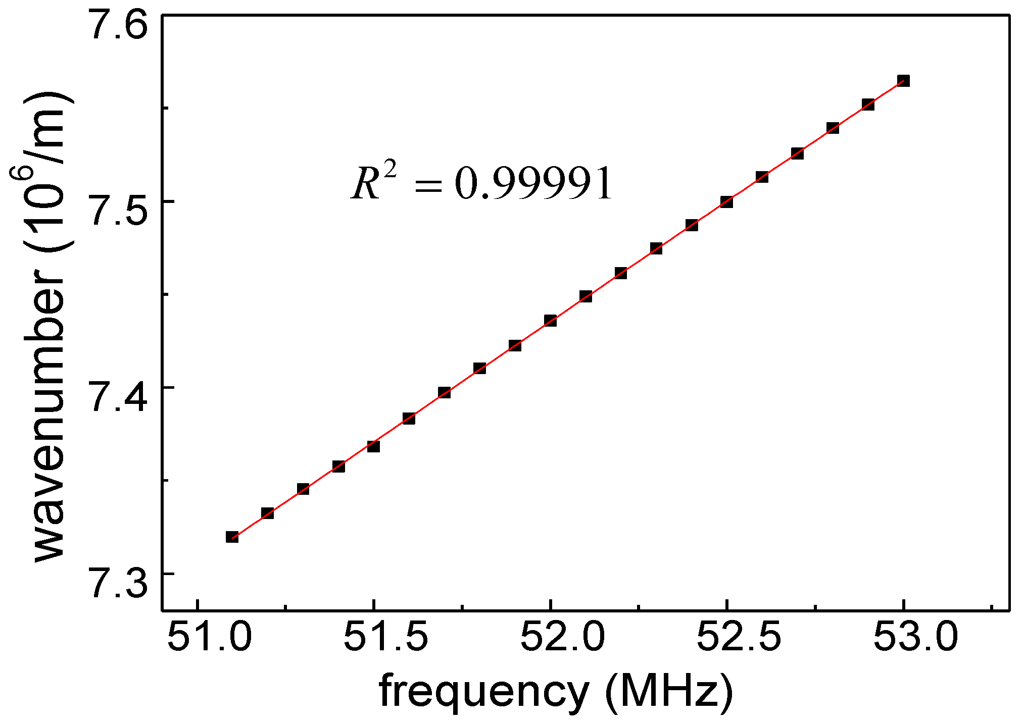
Figure 3 shows the relationship between the applied RF and the wavenumber of the laser output. As described by Equation (1), the applied RF is inversely proportional to the filtered wavelength and is therefore linearly proportional to the output wavenumber. This means that, as a wavenumber-linear drive function, the simple triangular drive function can be used to change the applied RF along the same time interval. We confirmed this validation by measuring the R-square value of the linearization factor to be 0.99991.
In addition to the wavenumber-linearity operation, the AOTF has other advantages as a key component in the swept source. Due to the characteristic of a non-mechanical filter, the enhanced environmental stability of this electro-optic swept source using the AOTF can be measured, in comparison with the conventional swept source based on the FFP-TF. Since the FFP-TF uses a mechanically vibrating resonator in the filter, it is known that this type of filter exhibits instability under harsh vibration or temperature drift conditions.
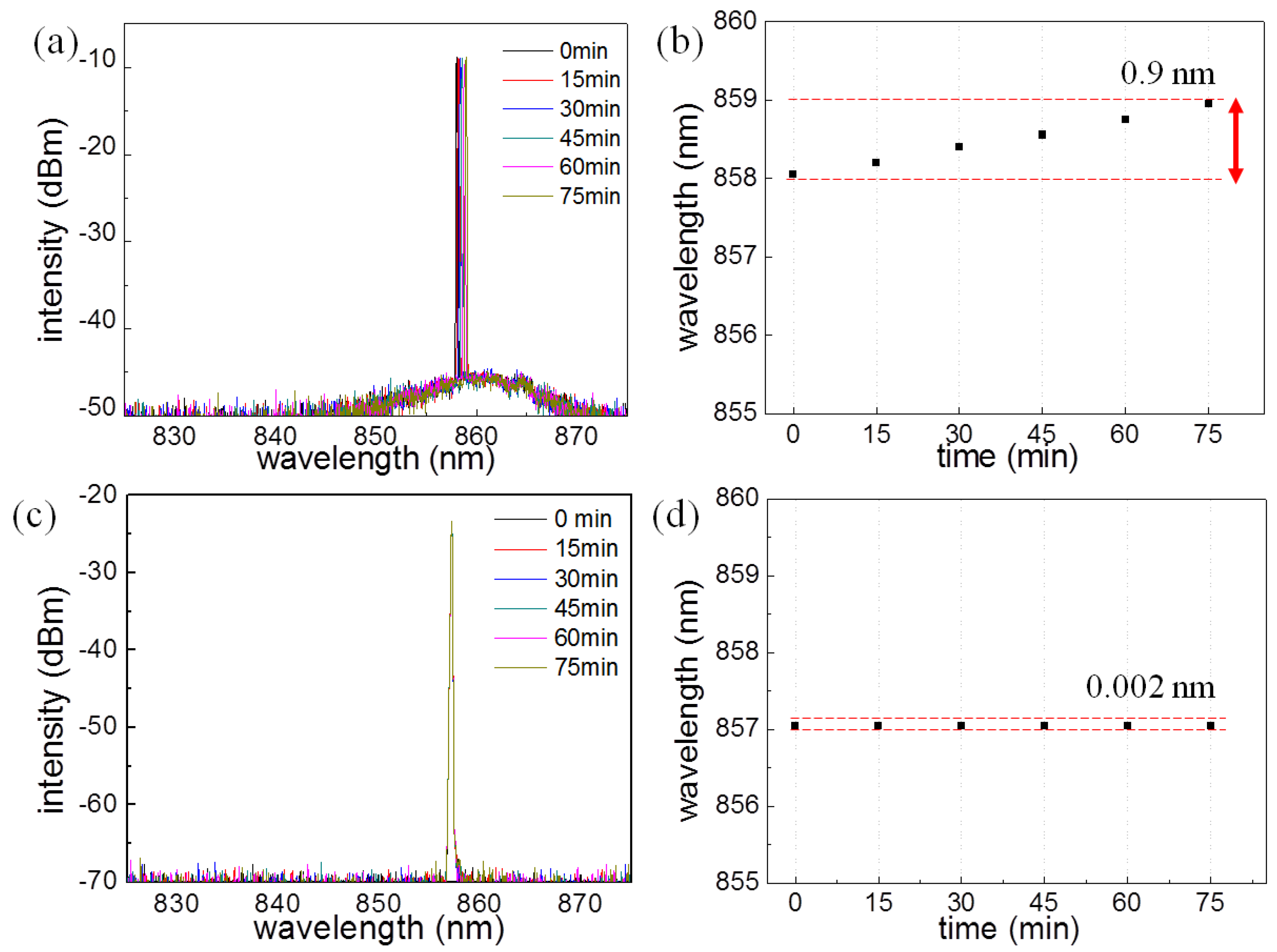
Figure 4 shows stability measurement results near an environmental temperature of 21 °C with two identical swept sources using the AOTF and the FFP-TF. We made six measurements at 15 min intervals. In the case of a swept source including the FFP-TF, as shown in
Figure 4a,b, the peak wavelength of the laser output was 858.05 nm for the first measurement of the spectrum. During the total 90 min, the measured peak was shifted along broad wavelength ranges from 858.05 to 858.95 nm (Δλ
shift = 0.9 nm).
Figure 4c,d show that the wavelength peak was first measured at the center wavelength of 857.05 nm with the swept source including the AOTF. In contrast, using the FFP-TF, the measured peaks were not shifted over the measurement resolution of the optical spectrum analyzer. The shifted wavelength range was within 857.048 nm to 857.05 nm (Δλ
shift = 0.002 nm), which confirms the advantage of an AOTF-based swept source for interferometric sensing and imaging applications in a harsh environment.
The non-mechanical operational property of an AOTF can demonstrate the advantage of electro-optic tuning of a swept source, such as various types of drive function to change the output wavelength arbitrarily.
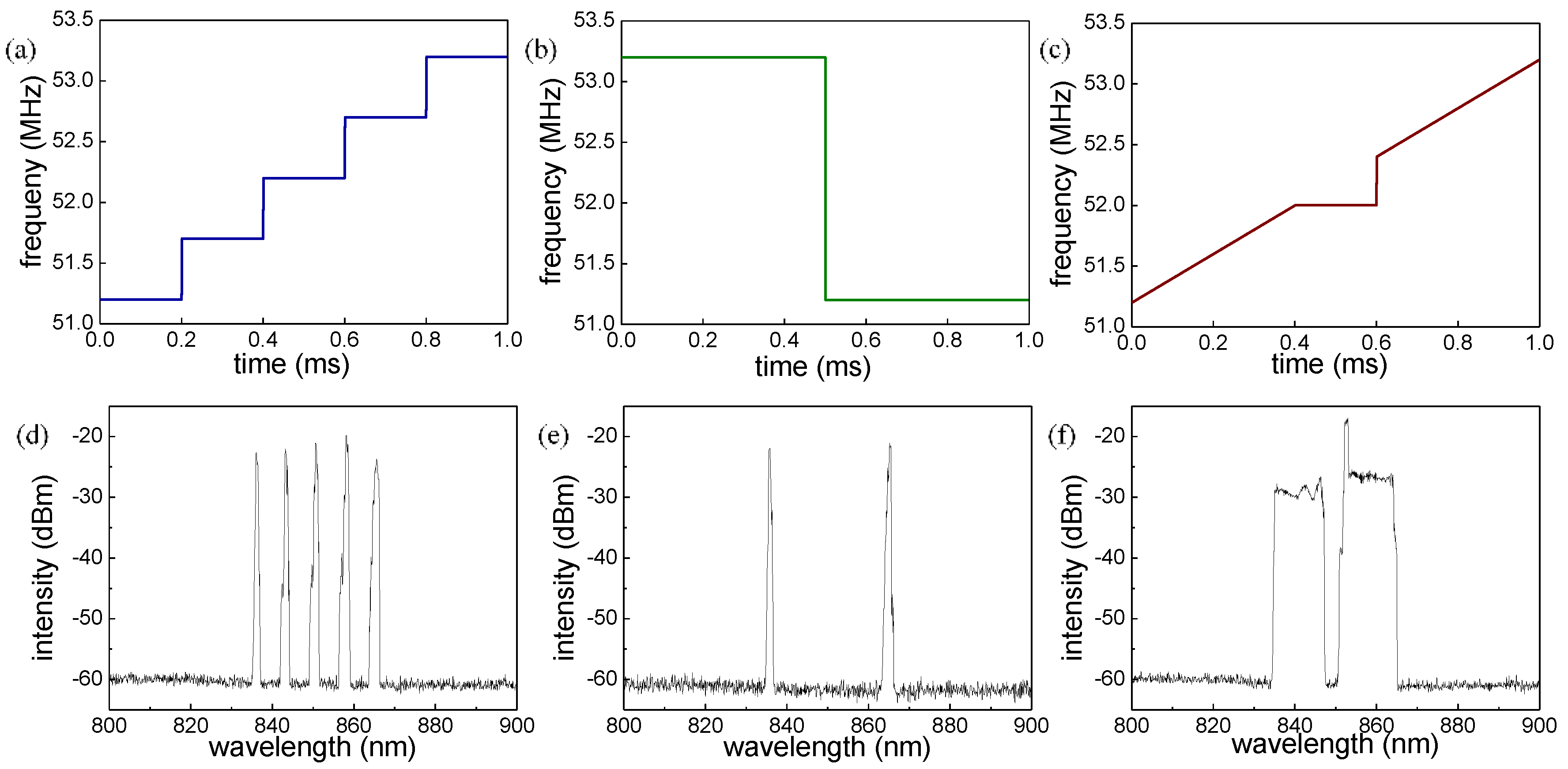
Figure 5 shows three types of programmed drive function: a staircase wave, a square wave, and a dual-band wave. In this experiment, the applied voltage of the drive function from AFG was used to change the applied RFs into the AOTF at the sweeping rate of 1 kHz, which is an appropriate speed for the sampling rate of our analog-to-digital converter. The deviation of this frequency modulation was around 1 MHz/V, which means that the 1 V of drive function corresponds to 1 MHz of applied RF. Since the applied voltage directly controls the output wavelength of the swept source with a sweeping rate of 1 kHz, the drive function of the five-step staircase shown in
Figure 5a can generate a tunable five-wavelength lasing output in sequence every 1 ms, as shown in the output spectrum measured with the peak hold mode in
Figure 5d. Similarly, the square waveform shown in
Figure 5b generates switching laser output between two wavelengths, as shown in
Figure 5e. The intervals of each laser peak are about 7.5 nm and 30 nm in
Figure 5b,d, respectively. Finally,
Figure 5c shows the drive function of a dual-band waveform; thus,
Figure 5f shows the peak hold mode spectrum of the dual-band laser sweeping output. It is monitored that the optical intensity at 854.7 nm looks relatively higher than the other region because the drive function remains at 51.95 MHz with a relatively longer duration. According to the measurement principle of peak-hold mode of the optical spectrum analyzer (OSA), it is evident that the one peak wavelength corresponding at 51.95 MHz was held at the relatively longer expose time of optical output power during 0.4–0.6 ms, compared to the transient wavelength regime during 0.0–0.4 ms, and the laser peak has moved quickly enough from one wavelength to the other at the timing of 0.6 ms to show a noise level spectrum during 0.4–0.6 ms.
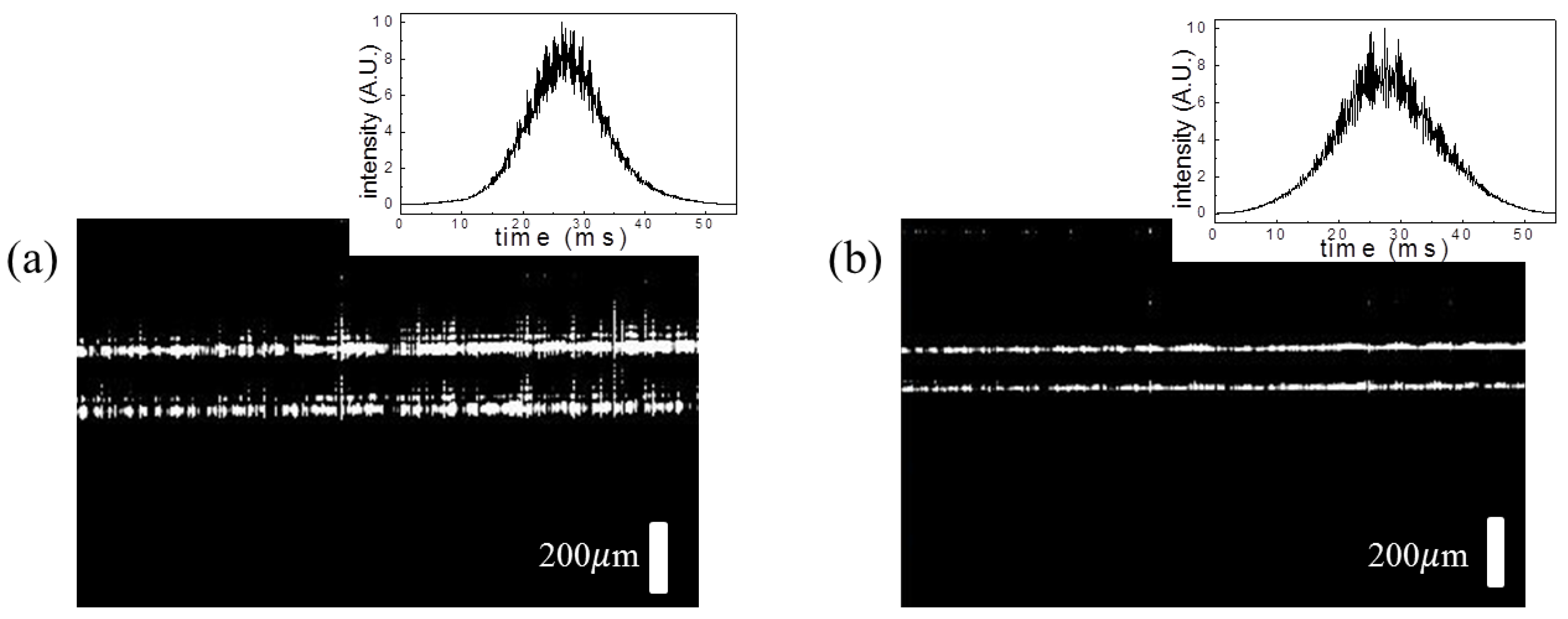
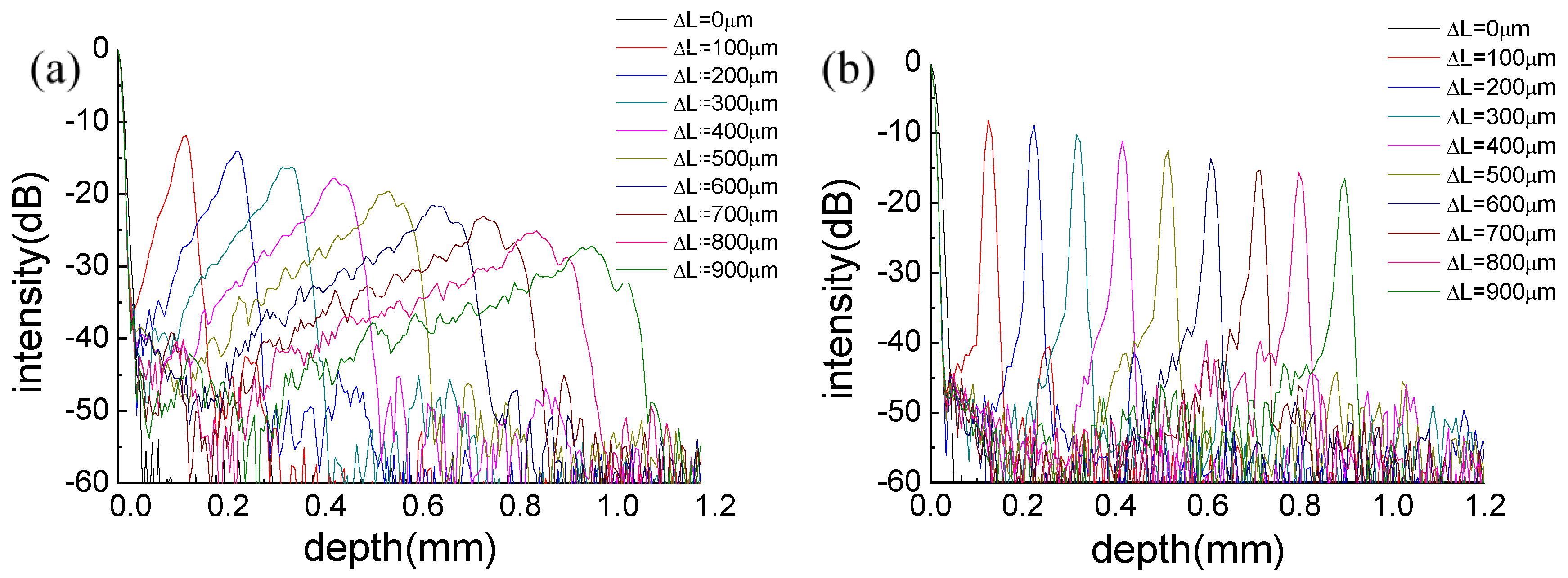
To demonstrate the improved image quality of OCT by using the wavenumber-linear drive function, we measured the roll-offs of point spread functions (PSFs) along the imaging depth with the OCT imaging setup in
Figure 1. For comparison, two types of drive function were applied to the AOTF: a sinusoidal drive function and a wavenumber-linear drive function of a triangular signal.
Figure 6a shows the measured PSF of the sinusoidal drive function. The total 6-dB roll-off value with the sinusoidal drive function is 0.42 mm. The PSF shapes broadened as the optical path length difference (ΔL) increased. Furthermore, the uncertainty of the peak position of the PSF was also observed at deeper imaging depths, which means that the OCT system is critically necessary in order to recalibrate the nonlinear problem of the wavenumber with respect to the time scale. The PSF of the triangular drive function is compared to the sinusoidal drive function in
Figure 6b. The total 6-dB roll-off value with the triangular drive function is 0.70 mm. In contrast to the sinusoidal sweeping, the PSF shapes of the triangular drive function did not broaden with the increased optical path length difference. Therefore, the system’s ability requires less processing time to measure the deeper depth images more clearly without recalibration.
Figure 7 also compares the 2-D OCT images that were obtained from both drive functions of the sinusoidal and triangular signals, respectively. The sample was selected with a cover glass with a thickness of 140 μm. The axial and transverse dimensions of each image are 1 mm × 1.5 mm, respectively. As shown in
Figure 7b, by applying the triangular drive function to the AOTF, the OCT image is more clearly measured in comparison with that of the sinusoidal drive function shown in
Figure 7a. It was observed that the thickness of the cover glass sample was more accurately measured in
Figure 7b, compared with the result in
Figure 7a.


