Article

Effect of Annealing Treatment on Microstructure and Properties of Cr-Coatings Deposited on AISI 5140 Steel by Brush-Plating

1
College of Material Science and Engineering, Chongqing University of Technology, Chongqing 400054, China
2
Chongqing Municipal Key Laboratory of Institutions of Higher Education for Mould Technology, Chongqing 400054, China
3
Faculty of Materials and Energy, Southwest University, Chongqing 400715, China
4
Department of Mechanical and Materials Engineering, Queen’s University, 60 Union Street, Kingston, ON K7L3N6, Canada
*
Authors to whom correspondence should be addressed.
Coatings 2018, 8(5), 193; https://doi.org/10.3390/coatings8050193
Submission received: 1 May 2018 / Revised: 15 May 2018 / Accepted: 17 May 2018 / Published: 21 May 2018
(This article belongs to the Special Issue Advanced Coatings for Corrosion Protection in Extreme Environments)

Abstract

:
Cr-coating was deposited on AISI 5140 steel by electro brush-plating, followed by annealing treatment at different temperatures, from 300 to 1100 °C. The microstructure evolution of the Cr-coating was characterized by backscattered electron imaging (BSEI) and energy dispersive spectrometry (EDS). The results show that the brush-plated sample has a nodular shaped microstructure, which is very stable at 300 °C of annealing. At 500 °C of annealing, the constitution of the microstructure changes from nodules to grains. As the annealing temperature further increases, the grains grow significantly. When the temperature reaches 1100 °C, a Cr-Fe solid-solution layer is formed within the original pure Cr-coatings. With increasing annealing temperature, the number of micro-cracks in the coating increases first and then decreases, reaching a maximum at 500 °C. The hardness and wear-resistance of the coating are improved when the annealing temperature increases to 1100 °C, owing to the decrease of micro-cracks that formed during brush-plating.

Graphical Abstract

1. Introduction

As the most important component in transmitting power and adjusting speed, the reliability of the gears within a machine determines the performance of the entire device [1,2]. The primary failure mode of gears is wear, which is a gradual loss of surface material due to interfacial interactions between two contacted parts [3]. To satisfy the high demands of the transmission system design within an aerospace system, for example, gears are being developed for high load, high speed, large gear ratio, high-efficiency transmission, lightweight, high reliability, and complicated usage conditions [4]. These conditions make the requirements for the wear resistance of the gear more demanding. In addition to improving the wear resistance by solid-solution precipitation of second-phase particles on the substrate via microalloying [5], surface modification by deposition or diffusion coating, such as plasma spraying [6,7], physical or chemical vapor deposition (PVD or CVD) [8,9], pulsed laser or laser cladding treatment [10,11], and thermo-diffusion coating [12,13] are considered effective ways to improve the wear resistance and meet the growing demand of conventional gear steels.
Electro brush-plating, also known as selective plating or swab coating, is considered a very useful and portable surface modification method for gear steels [14]. Brush-plating has been successfully applied to the preparation of single or multiple phase coatings on materials due to its easy-to-adjust coating thickness and good deposition quality [15,16,17,18]. The coatings deposited by brush-plating have excellent wear resistance, corrosion resistance, and high hardness [19,20,21]. Subramanian et al. [22] reported that brush-plated Ni coatings have better corrosion resistance than direct current magnetron sputtering deposited Ni. It has been pointed out that the formation of internal micro-cracks, the unstable bath composition, and the low current efficiency are the major drawbacks for the commercialization of trivalent hard chromium plating [23]. In a study of the influence of rare earth element addition on residual stress of the Fe-based coating, Guo et al. [24] demonstrated that the addition of rare earth elements transforms the residual stress from tensile to compressive, leading to a reduced number of cracks in the coatings. The prevention of the internal micro-cracks could significantly assist the commercialization of trivalent hard chromium plating due to better current efficiency from lower amounts of micro-cracks [23]. Ghaziof et al. [25] claimed that thermal treatments could promote the precipitation of Cr23C6, and thereby enhance the hardness of the amorphous Cr-C alloy coatings electrodeposited using direct current magnetron sputtering on a copper substrate. Due to the aforementioned advantages, the brush-plating method has been widely used in repairing and rebuilding components in transitions [26,27].
In this study, Cr-coatings were plated on commercial AISI 5140 steel and annealed at different temperatures with the aim to reduce micro-cracks and improve the properties of the Cr-coating. The microstructures of both the as-plated and annealed samples were characterized. The influence of annealing temperature on the microstructure, micro-cracks, and mechanical properties was investigated and the corresponding mechanisms were also studied.

2. Experimental Section

2.1. Materials and Methods

Commercial AISI 5140 steel was selected as the substrate material. The chemical composition was Fe-0.40C-0.23Si-0.27Mn-0.8Cr-0.030Ni by wt.%. Samples with gauge dimension of 25 × 20 × 6 mm3 were prepared for brush-plating. Manual brush-plating was performed on a MBPK-50A system (Wuhan Research Institute of Materials Protection, Wuhan, China) at room temperature with a voltage of 10 V and a duration of 10 min. The brush-plating parameters were as follows: Electrical cleaning at +10 V for 60 s, strong activation at −10 V for 30 s, weak activation at −18 V for 30 s, electro brush-plating at +10 V for 10 min. Prior to brush-plating, sample surfaces were mechanically polished using sandpaper followed by ultrasonic cleaning to improve the adhesion between the substrate and coatings.
After brush-plating, the samples were rinsed with running water and ethyl alcohol to clean the residual chromium solution. Then, the as-plated samples were subjected to annealing treatment in a vacuum furnace at 300, 500, 700, 900, and 1100 °C for 0.5 h (denoted as A300, A500, A700, etc.). After annealing, all samples were naturally cooled to room temperature.

2.2. Characterization

The microstructure and element distribution of the as-plated and annealed samples were characterized by backscattered electron imaging (BSEI), secondary electron imaging (SEI) and energy dispersive spectrometry (EDS) using a field emission scanning electron microscope (FE-SEM, Zeiss ΣIGMA HD, Zeiss, Dresden, Germany). Hardness tests were performed on a microhardness tester (HVS-1000, Shanghai CSOIF CO., LTD, Shanghai, China) with a load of 200 g and a loading time of 10 s. Prior to the microstructure and microhardness examinations, the samples were mechanically polished and then electropolished in an electrolyte of perchloric acid (10%) and ethanol (90%) at −20 °C. Friction and wear tests were carried out on a friction and wear tester (MS-T3001, Lanzhou Huahui Instrument Technology Co., LTD, Lanzhou, China) with a 5 mm steel ball (AISI52100). The parameters were as follows: Load 5 N, duration time 10 min, spinning speed 200 r/min, and rotation radius 3 mm.

3. Results and Discussion

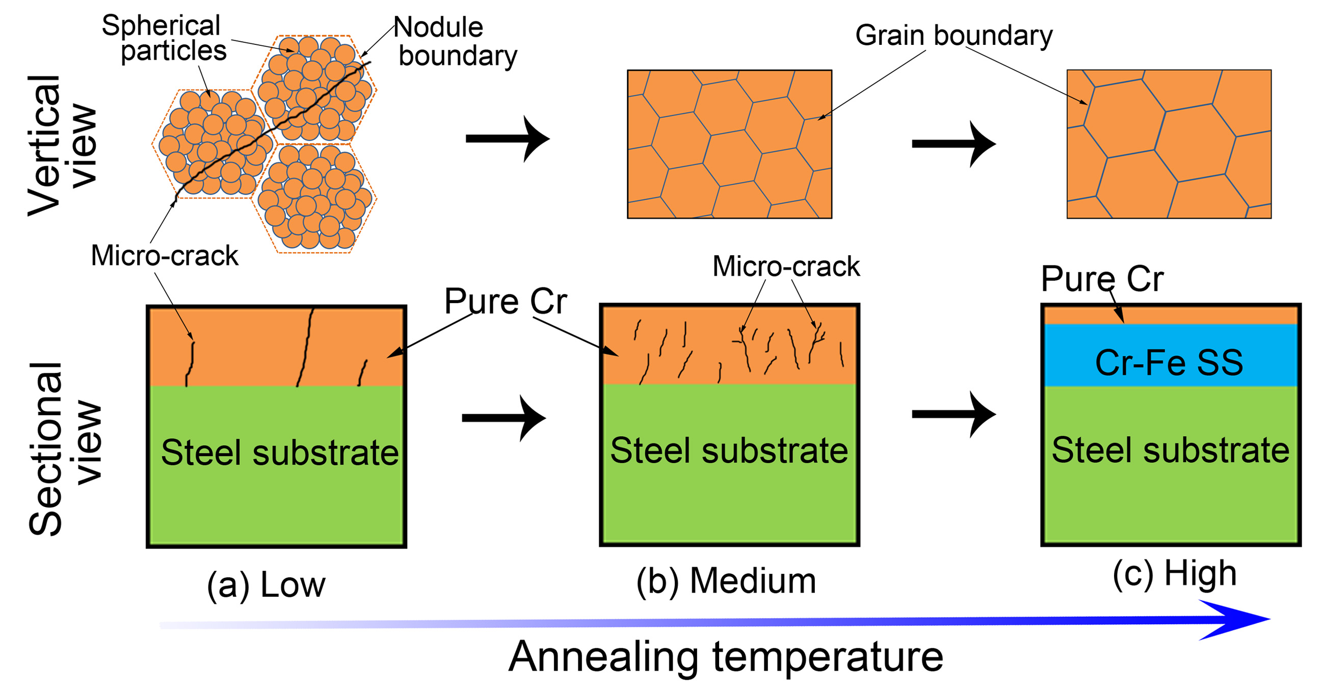
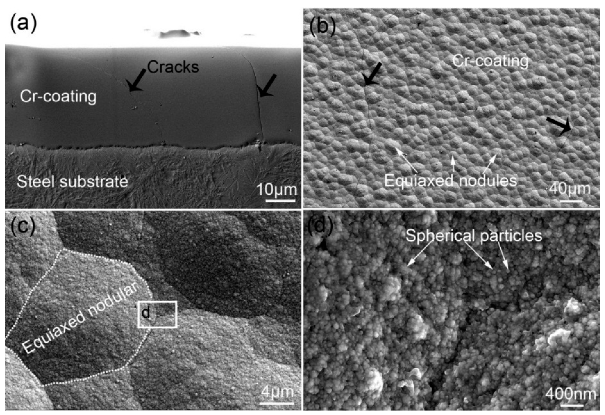
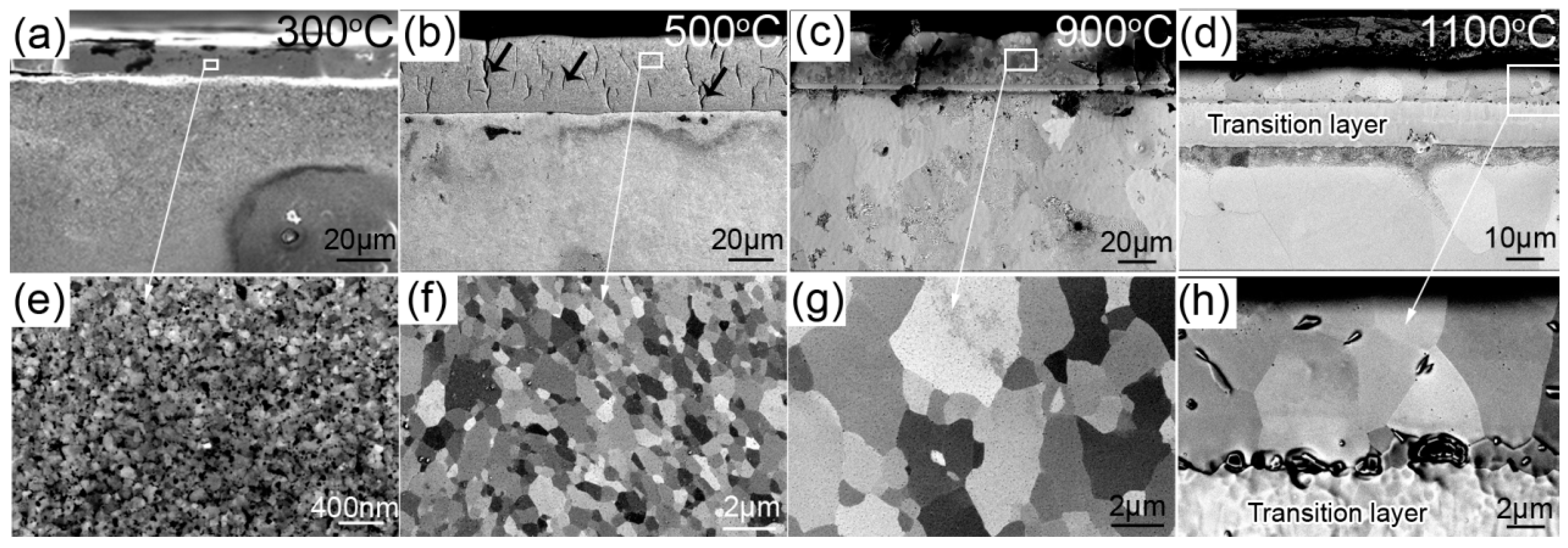
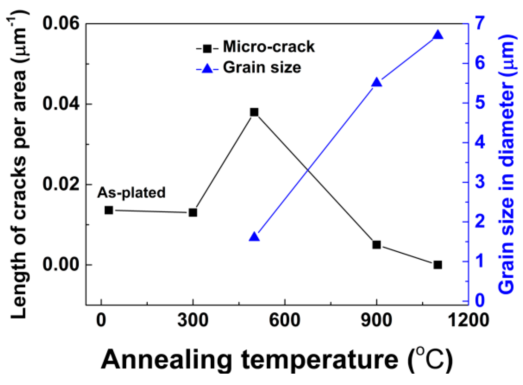
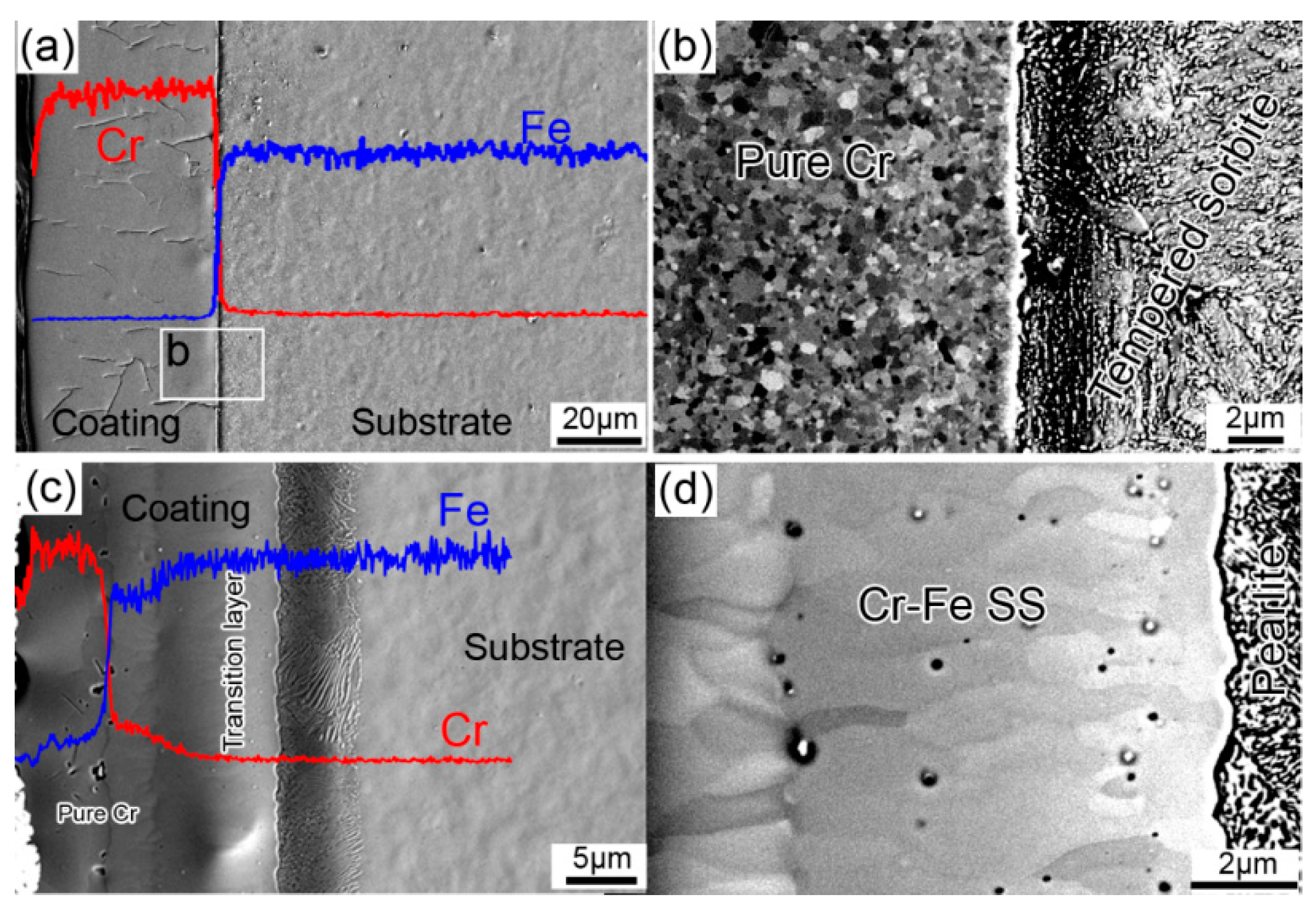
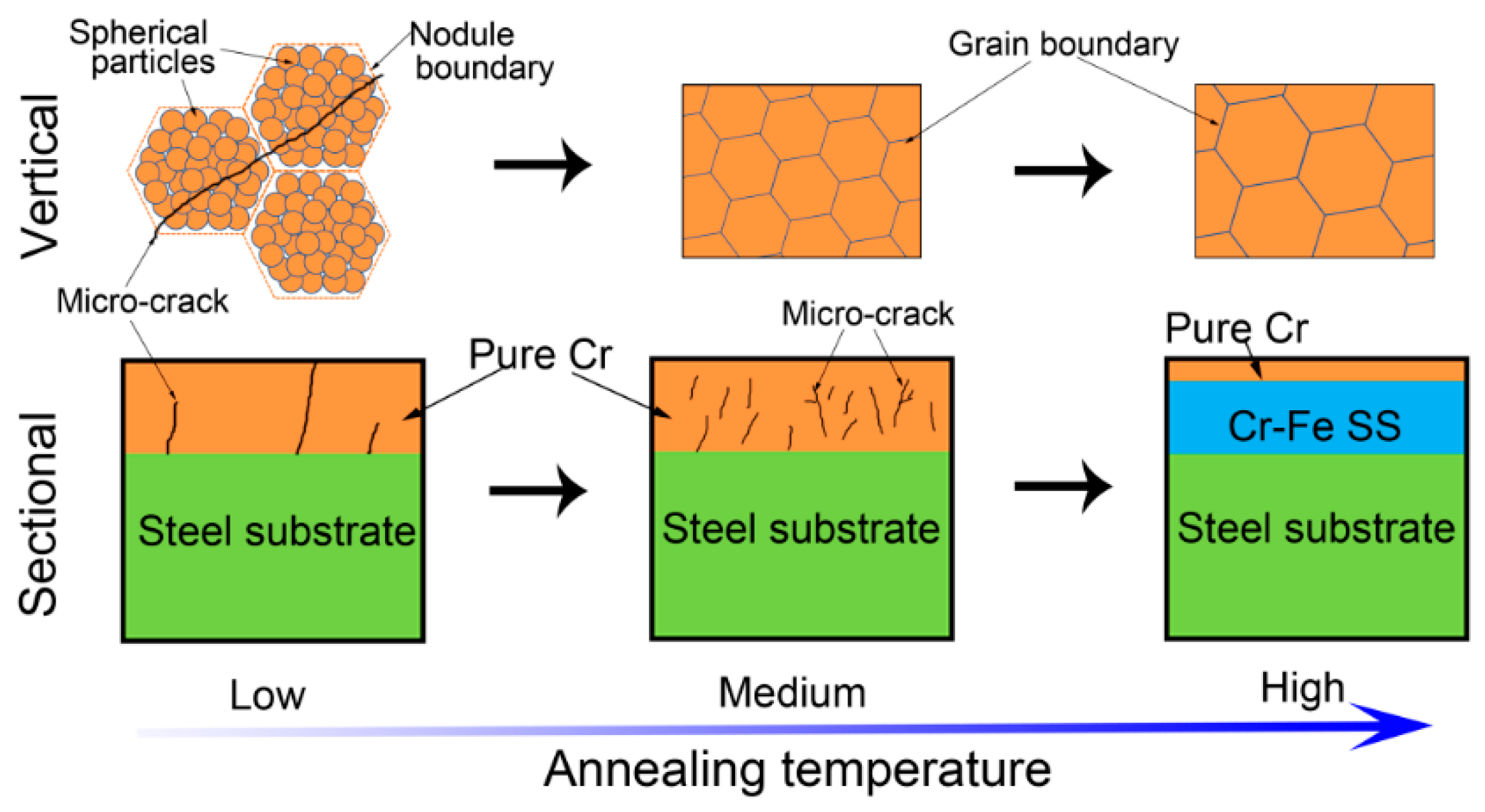
3.1. Microstructure Evolution

Figure 1 shows SEI images from the cross-sectional and vertical views of the as-plated sample. As shown in Figure 1a, the steel surface is evenly covered by a Cr-coating with no conspicuous pits. However, two long cracks are observed in the coating. The thickness of the Cr-coating layer is about 30 μm. Figure 1b,c shows that the Cr-coating layer has a rough surface and consists of equiaxed nodules with an average diameter of 15 μm. A highly-magnified image shows that equiaxed nodules are composed of distinct spherical particles with a diameter of 20–100 nm, as shown in Figure 1d. This structure consisting of nano-sized spheres has also been found in brush-plated Cr-coatings [4] and Ni-coatings [26,28]. Tan et al. [26] reported this nodular structure as cauliflower shaped, and pointed out that each cauliflower is a particle that consists of many small crystalline grains in the brush-plated Ni-coating. It has been reported that the sphere size is related to the movement speed between the anode and cathode, the continuous supply of plating solution, and the appropriate contact pressure [15]. Additionally, the micro-cracks which penetrate the entire coating are clearly observed from both the cross-sectional view (Figure 1a) and the vertical view (Figure 1b). The micro-cracks can grow either along the nodule boundaries or directly from the nodule interior (see Figure 1a). It has been pointed out that the formation and propagation of cracks are attributed to hydrogen evolution and stress generation during the electro brush-plating [23,25,29]. The existence of micro-cracks will deteriorate the quality of the coating. For instance, micro-cracks can reduce the adhesion of the coating to the substrate and decrease the corrosion and wear resistance, and even lead to premature fracture.
Figure 2 presents the BSEI images of the cross-sectional views of the samples annealed at various temperatures. Figure 2a,e shows the microstructure of the A300 sample. Compared to the as-plated state, the microstructure does not change substantially, indicating that the nodular morphology is very stable at 300 °C of annealing. As shown in Figure 2b,f, when the annealing temperature is increased to 500 °C, the nodular morphology of the Cr-coating disappears and is replaced by the polycrystalline characteristic. The average grain size is determined to be 1.6 μm (see Figure 2f). Unexpectedly, there is a significant increase in the number of micro-cracks in A500 compared to the as-plated sample (see Figure 2b). As the annealing temperature is further increased to 900 °C, the grain grows significantly to about 5.5 μm (see Figure 2g). Meanwhile, the number of micro-cracks seemingly decreases (see Figure 2c). When the temperature rises to 1100 °C, a transition layer (about 11.0 μm in thickness) is formed within the Cr-coating side, as shown in Figure 2d. The average grain size is around 6.7 μm and no obvious micro-cracks are observed in the coating (see Figure 2h).
The length per area of micro-cracks and the average grain size are measured and shown in Figure 3. As the annealing temperature increases, the coating thickness does not change significantly (see Figure 2), but the total length of the micro-cracks in the coating increases first and then decreases. The reason for this change in micro-crack length can be attributed to the diffusion of Cr atoms in the coatings, which leads to the formation and growth of bulk Cr grains during annealing. At 500 °C, the diffusion rate of Cr atoms in the coating is significantly enhanced. Therefore, the voids between the spherical particles collapse and the nodules are transformed into grains. This transformation has been seen in other work where it was reported that, after annealing at 450 °C for 1 h, an as-deposited amorphous structure of a Ni-P coating is transformed into a polycrystalline Ni and Ni3P structure [30]. The void collapse and grain growth will inevitably lead to volume shrinkage in their local volumes and initiate micro-cracks within the coating. However, when the annealing temperature is high enough, the void collapse is consumed by the grain growth. Due to the high surface energy of the micro-cracks, the micro-cracks coalesce into larger pores or migrate to the surface of the material during the high-temperature annealing, thereby reducing or even eliminating the micro-cracks within the coating.
BSEI images and EDS line scans of the A500 and A1100 samples are shown in Figure 4. These images show that, although the coating is composed of grains at 500 °C (see Figure 4b), there is no significant interdiffusion between the Cr-coating and the steel substrate, as seen in the EDS results (see Figure 4a). In contrast, there is significant interdiffusion between the coating and the substrate at 1100 °C, as seen in the EDS line scan in Figure 4c. This fast diffusion led to the formation of the diffusion layer (transition layer in Figure 2d) within the original pure Cr-coating near the side of the substrate (see Figure 4d). Such a diffusion layer is composed of a columnar grained Cr-Fe solid-solution (Cr-Fe SS), which has been reported to occur in Cr-coated steels prepared by pack-chromizing at 1100 °C [13]. In addition, the matrix of the A500 sample is tempered sorbite, while the matrix of the A1100 sample is pearlite. For the latter, the annealing temperature is the austenite phase field, and pearlite transformation occurs during cooling.
Figure 5 illustrates the microstructure evolution of the brush-plated Cr-coating with increasing annealing temperature. At a low temperature (<500 °C), the coating remains the nodular structure of the as brush-plated state with a small number of micro-cracks. The nodular structure is composed of numerous nano-sized Cr particles. At a medium temperature (500–1100 °C), the Cr atoms start to diffuse and the voids between the nano-sized Cr spheres collapse. The constitution of the coating evolves from nodules to grains. During this period, the number of micro-cracks is dramatically increased due to the localized volume shrinkage caused by the void collapse and grain growth. At a high temperature (~1100 °C), the layer close to the coating surface is still a pure Cr layer with notably coarsened grains. However, the layer close to the substrate is Cr-Fe SS with large columnar grains. Meanwhile, the number of the micro-cracks is significantly reduced due to a minimization of the system energy.

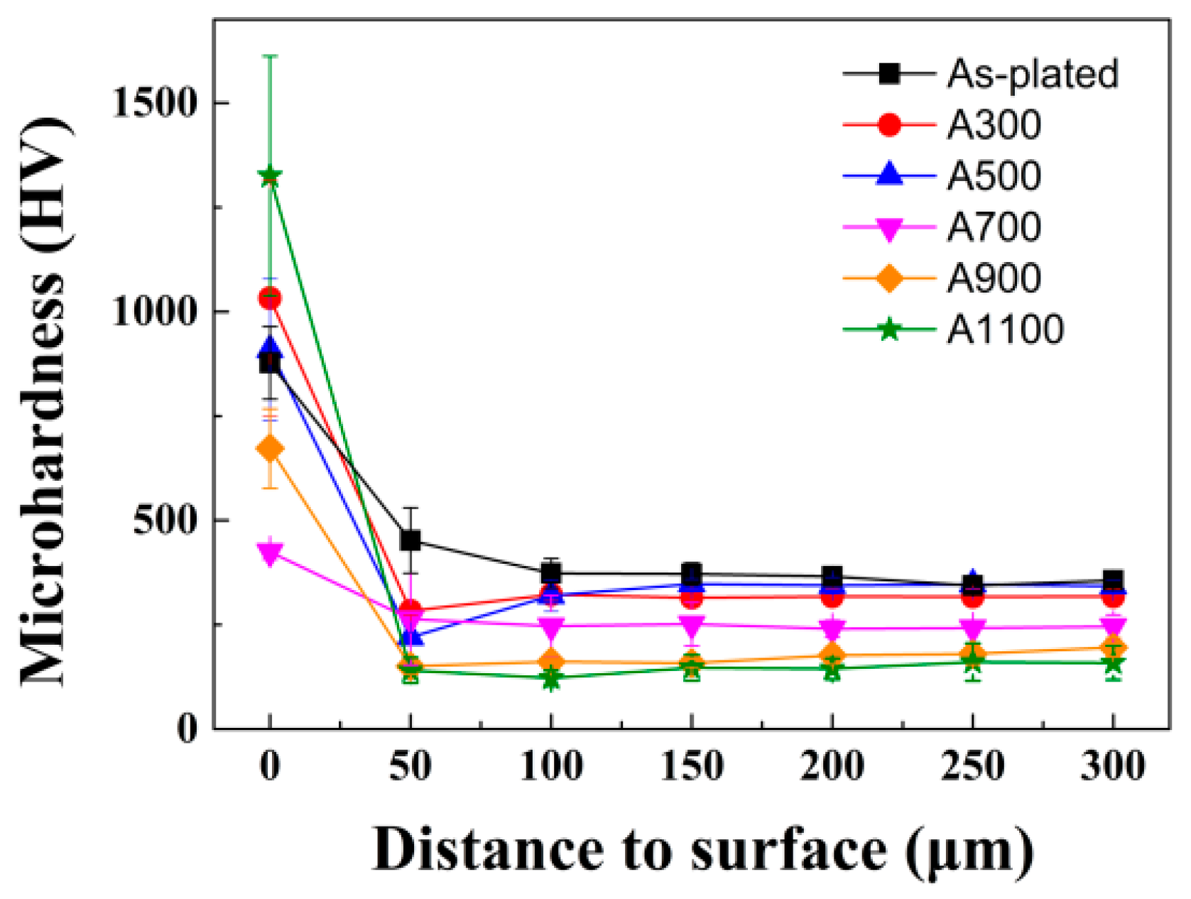
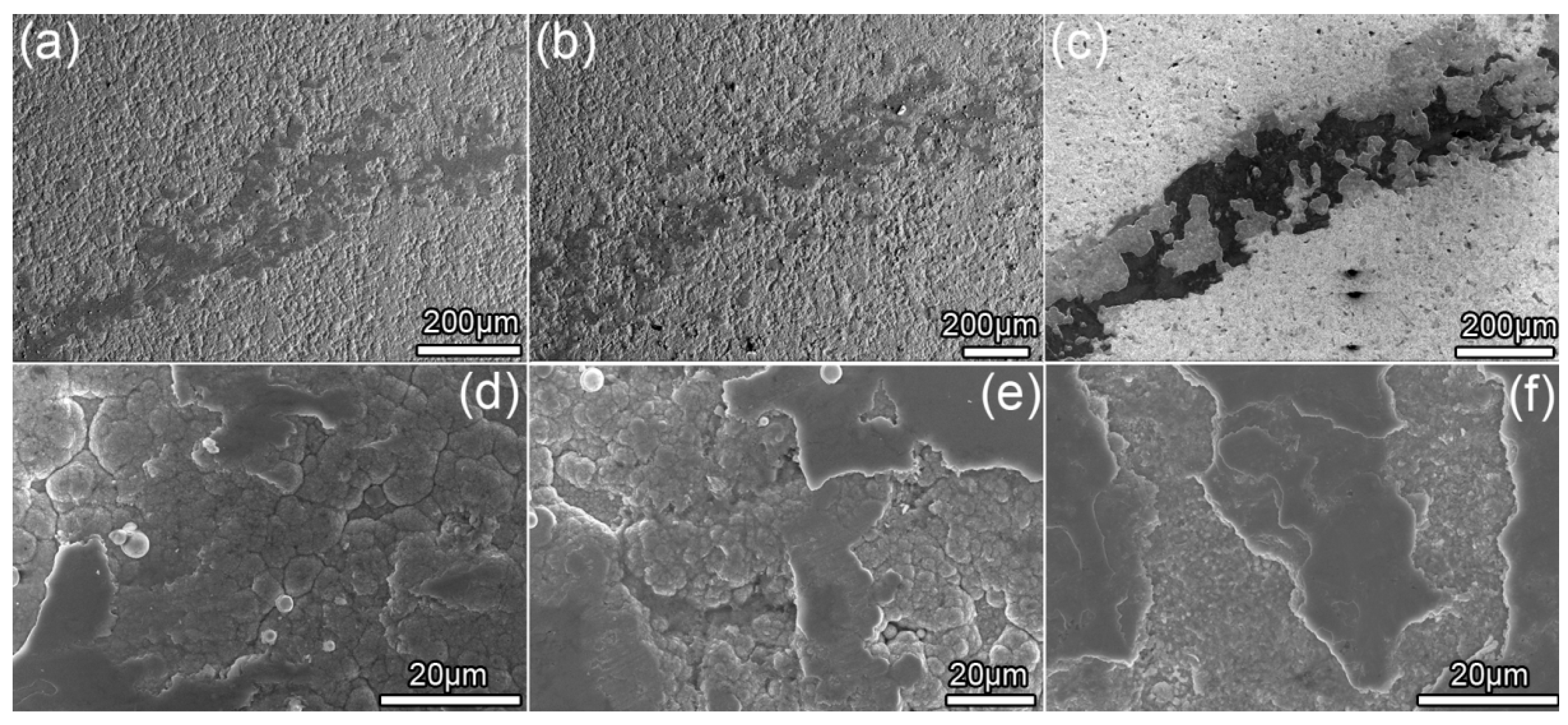
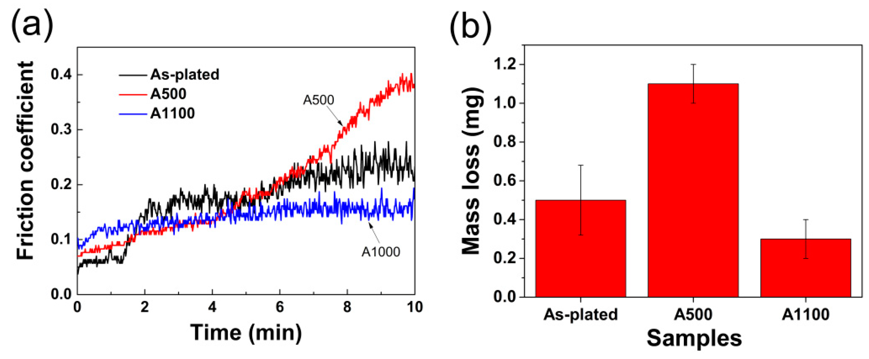
3.2. Mechanical Properties

Figure 6 displays the microhardness distribution relative to the distance from the sample surface in various samples. The hardness of the as-plated and annealed samples gradually decreases along the depth direction and tends to stabilize at the steel substrate. The coating hardness decreases constantly with increasing annealing temperature when the annealing temperature is between 300 and 700 °C. This decrease in hardness is mainly due to the increase of micro-cracks and elimination of internal stress that was formed during plating. However, when annealed at a temperature between 700 and 1100 °C, the hardness of the coating increases with increasing annealing temperature due to the formation and growth of chromium crystals and the elimination of micro-cracks. Therefore, although the grain coarsens significantly as the annealing temperature increases, the Cr-coating of the A1100 sample has the highest hardness (1350 HV) compared to the as-plated and other annealed samples. The phenomenon that the hardness of the coating increases with the annealing temperature is also reported in the reactive radio frequency magnetron sputter-deposited chromium oxide coatings [31]. Additionally, the Cr-Fe SS layer formed at 1100 °C annealing is believed to have solid-solution reinforcement due to the lattice distortion caused by the dissolution of Fe into Cr [13]. Therefore, we conclude that the main reason for the A1100 sample coating having the highest micro-hardness value is because of the reduction of micro-cracks and increase in density, along with the additionally solid-solution strengthening.
Figure 7 shows wear morphology of various samples, which show that the wear scar width of the as-plated sample is about 343 μm (see Figure 7a,d). For the A500 sample, the wear scar width sharply increases to about 580 μm (see Figure 7b,e), indicating a significant decrease in wear resistance due to the increase of micro-cracks within the Cr-coatings during annealing at 500 °C. The wear scar width of the A1100 sample decreases to about 270 μm (see Figure 7c,f), indicating that the wear resistance is improved again due to the elimination of the micro-cracks within the coatings during annealing at 1100 °C. The experimental results of the changes in friction coefficient and sample mass further confirm this evolution, as shown in Figure 8. The friction coefficients plotted as a function of the friction time of various samples are displayed in Figure 8a. It has been reported that in the initial stage of friction (<1 min), the friction coefficients are affected significantly by the surface quality (e.g., roughness, oxidation, and contamination), and the curve ranging from 1 to 10 min is probably the real friction coefficient [32]. Furthermore, when compared to the as-plated sample, as wear time increases, the wear coefficient of the A500 sample increases significantly and there is no tendency towards stabilization. In contrast, for the A1100 sample, the wear coefficient only slightly increases with the increasing wear time and tends to stabilize when worn for 6 min. When the wear time is longer than 6 min, the friction coefficient of the A1100 sample is significantly lower than that of the as-plated and the A500 samples, indicating that the A1100 sample has the best wear resistance during prolonged service. For the A500 sample, the abrasion resistance of the coating is seriously degraded due to the high number of micro-cracks in the coating that accelerates the wear of the coating. Figure 8b shows the statistical results of the mass loss after the abrasion test. These results indicate that the wear resistance of the coating deteriorates after annealing at 500 °C and becomes better when annealing at 1100 °C.
It is also worth noting that both the hardness and wear resistance of the coatings are improved after the annealing treatments, but the hardness and strength of the steel substrate are noticeably reduced. To obtain a high hardness and strength of the steel substrate, it is necessary to increase cooling rate after annealing to reduce the coarsening of the steel substrate, thereby reducing the effect of the annealing treatment on the strength and hardness of the substrate.

4. Conclusions

Cr-coating was deposited on the AISI 5140 steel by electro brush-plating and subsequently annealed at different temperatures from 300 to 1100 °C. The influence of annealing temperature on microstructure, micro-cracks, and properties was characterized and studied. The main conclusions are as follows:
At low temperature (<500 °C), the coating remains as a nodular structure, which is composed of large amounts of nano-sized Cr particles. As the annealing temperature increases to 500 °C, the constitution of the microstructure changed from nodules to grains.
As the annealing temperature is further increased to 1100 °C, the layer close to the coating surface is still pure Cr with notably coarsened grains, while the layer close to the substrate is Cr-Fe SS with large columnar grains.
With the increase of annealing temperature, the number of micro-cracks in the coating increases first and then decreases. When annealed at 500 °C, the number of micro-cracks is highest due to local volume shrinkage, which induced new micro-crack formation caused by the void collapse of the nano-sized Cr particles within the original nodules.
The hardness and wear-resistance of the coating are improved when the annealing temperature is increased to 1100 °C, owing to the solid-solution strengthening of the new formed Cr-Fe SS layer and the decrease of micro-cracks within the Cr-coatings. For the brush-plated Cr coatings, high-temperature annealing is recommended to promote nodular-to-grain transformation to increase coating adhesion and eliminate micro-cracks within the coating, thereby increasing the hardness and wear resistance of the coating.

Author Contributions

Methodology, J.J., H.L., X.Y., Y.J. and C.M.; Software, N.G.; Validation, J.H., H.X. and N.G.; Formal Analysis, J.H. and J.J.; Investigation, J.H. and J.J.; Resources, H.L. and X.Y.; Data Curation, J.H., J.J. and C.M.; Writing-Original Draft Preparation, J.H., J.J. and N.G.; Writing-Review & Editing, Q.D. and H.X.; Visualization, J.H. and J.J.; Supervision, H.X.; Project Administration, H.X.; Funding Acquisition, J.H., H.X. and N.G.

Funding

This research was funded by the Natural Science Foundation of China (51575073, 51275548 and 51501158), International Cooperation Special Project in Science and Technology of China (2015DFR70480), Scientific and Technological Research Program of Chongqing (cstc2017jcyjBX0031, cstc2014gjhz70003 and cstc2014yykfA70001), and Program for Innovation Team Building at Institutions of Higher Education in Chongqing (CXTDG20162017).

Acknowledgments

N.G. thanks to the support from the China Scholarship Council (No. 201706995008) during his visiting at Queen's University.

Conflicts of Interest

The authors declare no conflict of interest.

References

  1. Dengo, C.; Meneghetti, G.; Dabalà, M. Experimental analysis of bending fatigue strength of plain and notched case-hardened gear steels. Int. J. Fatigue 2015, 80, 145–161. [Google Scholar] [CrossRef]
  2. Tobie, T.; Hippenstiel, F.; Mohrbacher, H. Optimizing gear performance by alloy modification of carburizing steels. Metals 2017, 7, 415. [Google Scholar] [CrossRef]
  3. Qiu, Z.-K.; Zhang, P.-Z.; Wei, D.-B.; Wei, X.-F.; Chen, X.-H. A study on tribological behavior of double-glow plasma surface alloying W-Mo coating on gear steel. Surf. Coat. Technol. 2015, 278, 92–98. [Google Scholar] [CrossRef]
  4. Hu, J.; Ma, C.; Xu, H.; Guo, N.; Hou, T. Development of a composite technique for preconditioning of 41Cr4 steel used as gear material: Examination of its microstructural characteristics and properties. Sci. Technol. Nucl. Install. 2016, 2016, 6. [Google Scholar] [CrossRef]
  5. Wang, Y.; Zhou, M.; Pang, X.; Volinsky, A.; Chen, M.; Gao, K. Applications and thermodynamic analysis of equilibrium solution for secondary phases in Ti–N–C gear steel system with nano-particles. Metals 2017, 7, 110. [Google Scholar] [CrossRef]
  6. Tian, L.; Feng, Z.; Xiong, W. Microstructure, microhardness, and wear resistance of AlCoCrFeNiTi/Ni60 coating by plasma spraying. Coatings 2018, 8, 112. [Google Scholar] [CrossRef]
  7. Akbarzadeh, A.; Khonsari, M. Effect of untampered plasma coating and surface texturing on friction and running-in behavior of piston rings. Coatings 2018, 8, 110. [Google Scholar] [CrossRef]
  8. Paiva, J.; Fox-Rabinovich, G.; Locks Junior, E.; Stolf, P.; Seid Ahmed, Y.; Matos Martins, M.; Bork, C.; Veldhuis, S. Tribological and wear performance of nanocomposite PVD hard coatings deposited on aluminum die casting tool. Materials 2018, 11, 358. [Google Scholar] [CrossRef] [PubMed]
  9. Damm, D.; Contin, A.; Barbieri, F.; Trava-Airoldi, V.; Barquete, D.; Corat, E. Interlayers applied to CVD diamond deposition on steel substrate: A review. Coatings 2017, 7, 141. [Google Scholar] [CrossRef]
  10. Chai, L.; Wang, S.; Wu, H.; Yang, Z.; Pan, H.; Song, B.; Guo, N. Bimodal plate structures induced by pulsed laser in duplex-phase Zr alloy. Sci. China Technol. Sci. 2017, 60, 587–592. [Google Scholar] [CrossRef]
  11. Chen, Y.; Guo, Y.; Lu, B.; Xu, M.; Xu, J. Microstructure and properties of the interface area in the laser cladded Ni based coatings on the 1Cr10Mo1niwvnbn steel. Metals 2017, 7, 175. [Google Scholar] [CrossRef]
  12. Sen, S.; Sen, U. Sliding wear behavior of niobium carbide coated AISI 1040 steel. Wear 2008, 264, 219–225. [Google Scholar] [CrossRef]
  13. Hu, J.; Zhang, Y.; Yang, X.; Li, H.; Xu, H.; Ma, C.; Dong, Q.; Guo, N.; Yao, Z. Effect of pack-chromizing temperature on microstructure and performance of AISI 5140 steel with Cr-coatings. Surf. Coat. Technol. 2018, 344, 656–663. [Google Scholar] [CrossRef]
  14. Subramanian, B.; Mohan, S.; Jayakrishnan, S. Selective area deposition of tin–nickel alloy coating—An alternative for decorative chromium plating. J. Appl. Electrochem. 2007, 37, 219–224. [Google Scholar] [CrossRef]
  15. Hu, J.J.; Chai, L.J.; Xu, H.B.; Ma, C.P.; Deng, S.B. Microstructural modification of brush-plated nanocrystalline Cr by high current pulsed electron beam irradiation. J. Nano Res. SW 2016, 41, 87–95. [Google Scholar] [CrossRef]
  16. Dey, S.; Chatterjee, S.; Singh, B.P.; Bhattacharjee, S.; Rout, T.K.; Sengupta, D.K.; Besra, L. Development of superhydrophobic corrosion resistance coating on mild steel by electrophoretic deposition. Surf. Coat. Technol. 2018, 341, 24–30. [Google Scholar] [CrossRef]
  17. Chen, T.; Ge, S.; Liu, H.; Sun, Q.; Zhu, W.; Yan, W.; Qi, J. Fabrication of low adhesive superhydrophobic surfaces using nano Cu/Al2O3 Ni–Cr composited electro-brush plating. Appl. Surf. Sci. 2015, 356, 81–90. [Google Scholar] [CrossRef]
  18. Kosugi, D.; Hagio, T.; Kamimoto, Y.; Ichino, R. Effect of the addition of molybdenum on the structure and corrosion resistance of zinc–iron plating. Coatings 2017, 7, 235. [Google Scholar] [CrossRef]
  19. Ma, G.; Xu, B.; Wang, H.; Wang, X.; Li, G.; Zhang, S. Research on the microstructure and space tribology properties of electric-brush plated Ni/MoS2–C composite coating. Surf. Coat. Technol. 2013, 221, 142–149. [Google Scholar] [CrossRef]
  20. Xu, B.; Wang, H.; Dong, S.; Jiang, B. Fretting wear-resistance of Ni-base electro-brush plating coating reinforced by nano-alumina grains. Mater. Lett. 2006, 60, 710–713. [Google Scholar]
  21. Du, L.; Xu, B.; Dong, S.; Yang, H.; Wu, Y. Preparation, microstructure and tribological properties of nano-Al2O3/Ni brush plated composite coatings. Surf. Coat. Technol. 2005, 192, 311–316. [Google Scholar] [CrossRef]
  22. Subramanian, B.; Mohan, S.; Jayakrishnan, S.; Jayachandran, M. Structural and electrochemical characterization of Ni nanostructure films on steels with brush plating and sputter deposition. Curr. Appl. Phys. 2007, 7, 305–313. [Google Scholar] [CrossRef]
  23. Lee, D.B. Oxidation of Cr–C electroplating between 400 and 900 °C in air. Mater. Corros. 2008, 59, 598–601. [Google Scholar] [CrossRef]
  24. Jin, G.; Lu, B.; Hou, D.; Cui, X.; Song, J.; Liu, E. Influence of rare earths addition on residual stress of Fe-based coating prepared by brush plating technology. J. Rare Earth 2016, 34, 336–340. [Google Scholar] [CrossRef]
  25. Ghaziof, S.; Golozar, M.A.; Raeissi, K. Characterization of as-deposited and annealed Cr–C alloy coatings produced from a trivalent chromium bath. J. Alloy. Compd. 2010, 496, 164–168. [Google Scholar] [CrossRef]
  26. Tan, J.; Yu, T.; Xu, B.; Yao, Q. Microstructure and wear resistance of nickel–carbon nanotube composite coating from brush plating technique. Tribol. Lett. 2006, 21, 107–111. [Google Scholar] [CrossRef]
  27. Wu, B.; Xu, B.-S.; Zhang, B.; Jing, X.-D.; Liu, C.-L. Automatic brush plating: An update on brush plating. Mater. Lett. 2006, 60, 1673–1677. [Google Scholar] [CrossRef]
  28. Wu, B.; Xu, B.-S.; Zhang, B.; Lü, Y.-H. Preparation and properties of Ni/nano-Al2O3 composite coatings by automatic brush plating. Surf. Coat. Technol. 2007, 201, 6933–6939. [Google Scholar] [CrossRef]
  29. Li, W.H.; Zhou, X.Y.; Xu, Z.; Yan, M.J. Effect of bath temperature on nanocrystalline Ni-polytetrafluoroethylene composite coatings prepared by brush electroplating. Surf. Eng. 2009, 25, 353–360. [Google Scholar] [CrossRef]
  30. Li, Z.; Qian, S.; Wang, W.; Shen, H.; Long, H. High-temperature tribological properties of Ni–P alloy coatings deposited by electro-brush plating. Rare Met. 2011, 30, 669–675. [Google Scholar] [CrossRef]
  31. Pang, X.; Gao, K.; Luo, F.; Yang, H.; Qiao, L.; Wang, Y.; Volinsky, A.A. Annealing effects on microstructure and mechanical properties of chromium oxide coatings. Thin Solid Films 2008, 516, 4685–4689. [Google Scholar] [CrossRef]
  32. Hu, J.; Ma, C.; Yang, X.; Xu, H.; Guo, N.; Yu, H. Microstructure evolution during continuous cooling in AISI 5140 steel processed by induction heating chromizing. J. Mater. Eng. Perform. 2017, 26, 5530–5537. [Google Scholar] [CrossRef]
Figure 1. SEI images showing microstructure of the as-plated sample: (a) sectional view showing the coating and substrate; (b) vertical view showing cracks and equiaxed nodules; (c) high-magnification image showing nodule boundaries; (d) enlarged image of white box in (c).
Coatings 08 00193 g001
Figure 2. BSEI images showing microstructure and micro-crack evolution of the Cr-coating with annealing temperature: (a) A300; (b) A500; (c) A900; (d) A1100. Figures (eh) are the corresponding enlarged images of (ad), respectively.
Coatings 08 00193 g002
Figure 3. Micro-crack and grain size evolution of the Cr-coating with increasing annealing temperature.
Coatings 08 00193 g003
Figure 4. EDS line scans and BSEI images showing element distribution and microstructures of the coatings of A500 sample (a,b) and A1100 sample (c,d), respectively.
Coatings 08 00193 g004
Figure 5. Schematic diagram illustrating microstructure evolution during annealing.
Coatings 08 00193 g005
Figure 6. Microhardness evolution with increasing annealing temperature.
Coatings 08 00193 g006
Figure 7. Wear morphology of various samples: (a,d) as-plated; (b,e) A500; (c,f) A1100.
Coatings 08 00193 g007
Figure 8. Friction coefficient plotted as a function of sliding friction time (a) and weight loss (b) of various samples.
Coatings 08 00193 g008

