Fouling Release Coatings Based on Polydimethylsiloxane with the Incorporation of Phenylmethylsilicone Oil


1
Key Lab of Ship-Machinery Maintenance & Manufacture, Dalian Maritime University, Dalian 116026, China
2
Department of Materials Science and Engineering, Dalian Maritime University, Dalian 116026, China
*
Author to whom correspondence should be addressed.
Coatings 2018, 8(5), 153; https://doi.org/10.3390/coatings8050153
Submission received: 2 February 2018
/
Revised: 3 April 2018
/
Accepted: 10 April 2018
/
Published: 24 April 2018
(This article belongs to the Special Issue Advanced Coatings for Buildings)
Abstract
:In this study, phenylmethylsilicone oil (PSO) with different viscosity was used for research in fouling release coatings based on polydimethylsiloxane (PDMS). The surface properties and mechanical properties of the coatings were investigated, while the leaching behavior of PSO from the coatings was studied. Subsequently, the antifouling performance of the coatings was investigated by the benthic diatom adhesion test. The results showed that the coatings with high-viscosity PSO exhibited high levels of hydrophobicity and PSO leaching, while the high PSO content significantly decreased the elastic modulus of the coatings and prolonged the release time of PSO. The antifouling results indicated that the incorporation of PSO into coatings enhanced the antifouling performance of the coating by improving the coating hydrophobicity and decreasing the coating elastic modulus, while the leaching of PSO from the coatings improved the fouling removal rate of the coating. This suggests a double enhancement effect on the antifouling performance of fouling release coatings based on PDMS with PSO incorporated.
1. Introduction
Marine biofouling refers to the colonization of submerged surfaces by marine micro- and macro-organisms, and is a worldwide problem affecting maritime and aquatic industries [1,2,3,4,5]. For a long time, painting antifouling coatings on seawater-impregnated substrates has been an effective way to inhibit the attachment of marine organisms. It has been widely applied, such as in shipping vessels, heat exchangers, offshore rigs, jetties, aquaculture cages, and other submerged structures in the marine environment [6,7]. Meanwhile, one statistical analysis indicated that the practice saves the global shipping industry an estimated 150 billion US dollars per year [8]. Among them, self-polishing antifouling coatings incorporating tributyltin-based compounds (TBT-based coatings) are the most efficient. Unfortunately, with the development of relevant research, these coatings have been revealed as toxicants toward non-targeted species [2]. Furthermore, TBT compounds have also been reported to accumulate in mammals and debilitate the immune defenses of fish [2,3]. Therefore, in 2001 the International Marine Organization (IMO) forbade the use of TBT-based coatings. Moreover, the biocide used in the marine environment is now under strict control in many countries, and it has become a driving force for the development of environmentally-friendly alternative coatings, which mainly include fouling-resistant coatings, fouling release coatings, and fouling degrading coatings [8,9,10,11,12].
It is known that marine biofouling involves a wide variety of organisms (more than 4000 species have been identified) [12]. It has the following characteristics: the fouling organisms change very quickly, attaching to the growth is very easy, there is no selective attachment to most of the matrix materials, and the environmental adaptability of organisms is very strong. Therefore, it is difficult to completely reject the adhesion of the fouling organisms on the substrate. For fouling release coatings, by minimizing the adhesion strength between fouling organisms and the material surface, fouling may be readily removed by simple mechanical cleaning or hydrodynamic stress during navigation [13]. These coatings use physical means to protect the substrate immersed in seawater, and are not causes of environmental pollution. They are now widely used as environmentally-friendly alternatives [8,13].
Polydimethylsiloxane (PDMS) has a linear structure and is the most common hydrophobic material. The molecular structure of PDMS is arranged in helixes, whereas the outwards-directed methyl groups provide hydrophobicity [14,15]. PDMS with low surface energy and low elastic modulus reduces the adhesion of marine organisms [16,17]. It has been prepared for fouling release coatings, and the first organic PDMS-based polymer antifouling coating came out in 1972 [18].
The incorporation of non-reactive silicone oil in fouling release coatings based on PDMS has been seen since 1977 [19]. Related studies have suggested that silicone oil additives in fouling release PDMS coatings could reduce the coefficient of friction and favor an easier release of fouling organisms [20,21]. Further studies showed that the increase of interfacial slippage with silicone oil leached from the coated surfaces improved the fouling release performance [22]. Although the potential of silicone oil to affect the ability to overcome cellular barriers has been pointed out [17], there is no statistical evidence to support these concerns [13,20]. The incorporation of silicone oil into fouling release coatings based on PDMS showed that the amount of silicone oil was negligible [22,23], and the low toxicity of silicone oil caused little harm in marine life [24,25,26].
The research on the incorporation of silicone oil into coatings is mainly focused on the evaluation of antifouling behavior on certain specific fouling organisms by the leaching of silicone oil [20,21,22,23]. There is no related research on the choice of silicone oil, including viscosity and added amount. A particularly significant research gap exists regarding the effect of these factors on the leaching speed and the leaching percent of silicone oil. In this experiment, the phenylmethylsilicone oil (PSO) with different viscosity and content was incorporated into fouling release coatings based on PDMS. The effect of the leaching amount of PSO on the antifouling performance of the coating is studied herein, and the leaching cycle of PSO is predicted by a reasonable measurement. The analysis of related properties can reveal the reasons for the improvement of the antifouling performance of the coating.
2. Materials and Methods
2.1. Materials
Hydroxyl-terminated polydimethylsiloxane (PDMS) was obtained from Dayi Chemical Industry Co., Ltd. (Yantai, China). The kinematic viscosity of PDMS was 10,000 mm2/s and the relative molecular weight was about 60,000. Phenylmethylsilicone oil (PSO) was purchased from Shanghai Hualing Resin Co., Ltd. (Shanghai, China). The kinematic viscosity of PSO was 30 mm2/s, 75 mm2/s, and 100 mm2/s for products known as Si-30, Si-75, and Si-100, respectively. Tetraethylorthosilicate (TEOS) was obtained from Tianjin Kemiou Chemical Reagent Co., Ltd. (Tianjin, China). Bismuth neodecanoate (BiND) was obtained from Deyin Chemical Co., Ltd. (Shanghai, China). Xylene and ethyl acetate were also analytical grade and supplied by Yongda Chemical Reagent Co., Ltd. (Tianjin, China).
2.2. Preparation of Coating Samples
The coating was composed of three parts. Pre-dispersed slurry included PDMS and PSO. TEOS and xylene were mixed to make the curing agent, and the mixture of BiND and ethyl acetate was prepared into the catalytic agent. The two-stage process of the preparation method was as follows: PDMS (100 g) and PSO were added into a 500 mL stirring tank at 2000 rpm for 30 min. Afterward, coatings were prepared in a 20:4:1 weight ratio of PDMS (from the pre-dispersed slurry):curing agent:catalytic agent. The coating was brushed on glass slides with dimensions of 75 mm × 25 mm × 1 mm, and also poured into a Teflon mold with dimensions of 150 mm × 150 mm × 2 mm for at least 8 h to form a cross-linked elastomer. The blank control sample without PSO was set as A, and other experimental samples were set as Ax-y, where x represents the viscosity of PSO and y represents the mass of PSO.
2.3. Experimental Procedure
The antifouling performance of the fouling release coating based on PDMS depends mainly on the surface and mechanical properties. Therefore, we analyzed the effect of the PSO on the above properties. In this study, the change in surface properties was due to the change of the chemical composition caused by the incorporation of PSO, which could be analyzed by Fourier transform infrared (FTIR) spectroscopy. The influence of the PSO on the crosslink density of the coating was beneficial to the analysis of the coating’s mechanical properties. The focus of this study was on the observation of leaching PSO, including leaching amount and leaching percent. The leaching of the PSO with different viscosity and content needed to be characterized by reasonable parameters. Finally, the antifouling performance of the coating was analyzed. Error values are quoted as standard error of the mean (SEM), based on the number of samples analyzed (n).
2.4. Characterization
2.4.1. Surface Properties of the Coatings
Contact angle measurements were conducted using the sessile drop method on a JC2000C contact angle measurement system (Shanghai Zhongchen Co., Ltd., Shanghai, China). Three-microliter droplets of distilled H2O and CH2I2 were placed on the sample surface using a syringe. Digital images of the droplet silhouette were captured with a charge-coupled device camera and the contact angles were evaluated using the measuring angle method. Six points for each sample were tested for the contact angle measurement. The surface free energies were calculated from the measured water contact angles and diiodomethane contact angles using Owens two-liquid method [27].
In order to analyze the effect of the chemical composition on the surface properties of the coating, FTIR spectra were recorded on a Frontier PerkinElmer infrared spectrometer (Thermo Fisher Scientific Inc., Waltham, MA, USA) within a scan range of 4000–650 cm−1 and a resolution of 2 cm−1. For each sample, 32 scans were recorded and a high-performance diamond single-bounce Attenuated Total Reflection accessory was used. The spectral evaluation was performed using the Spectrum 10.3.6 software package from PerkinElmer.
2.4.2. Mechanical Properties of the Coatings
Tensile samples were prepared into strips with 150 mm × 20 mm × 2 mm and then stretched on a Labthink XLM auto tensile tester (Labthink Co., Ltd., Jinan, China) with the 1.15 software package. The tensile speed was at 50 mm/min. Elastic modulus was fitted with the data, which showed that the strain was less than 0.02 mm/mm. Three samples of each coating were prepared for the experiment. The stress–strain curves of the coatings were presented by selecting the data for which the elastic modulus value was close to the average value.
A HT220 shore hardness tester was applied to test the hardness of the coating. The thickness of the test sample must exceed 5 mm, and thus the prepared casting sample was folded repeatedly to meet the experimental requirement [28]. Similarly, three samples for each coating were used in the experiment.
In order to determine the origin of the mechanical properties of the coating, the crosslink density of the coating was measured by the equilibrium swelling method [29]. Generally, it can be expressed by the molecular weight between crosslink points (MC). Toluene was used as the solvent which could dissolve the PSO in the coating, and then the swelling of the gel could be determined. The value of MC was calculated by the Flory–Rhener relation,
where v represents the volume fraction of the polymer in the swollen specimen [29]; ρ represents the density of samples before swelling; V represents the molar volume of the solvent, and it is 106.125 cm3/mol for toluene; χ1 refers to the Flory–Huggins interaction parameter between the sample and toluene, and it is 0.45 in this experiment.
In order to ensure the accuracy of the experimental data, the weight of the sample was measured every 3 h by using a precision balance (Mettler Toledo Co., Ltd., Zurich, Switzerland) during the swelling process. When the difference of the adjacent measurement data did not exceed 0.1 mg, the sample was up to the equilibrium swelling state. The whole experiment was performed at 25 °C, while three samples for each coating were used in the experiment.
2.4.3. The Leaching Observation of the PSO
The morphology of the leached PSO on the sample surface was analyzed by an Olympus OLS4000 CLSM (OLYMPUS (China) Co., Ltd., Beijing, China) with a field of view 2575 μm × 2581 μm. The software version was 2.2.4.
The leaching percent of the PSO with exposure time was analyzed. Before brushing slide samples, the mass of the slide (m0) was measured with a precision balance, and the mass of the slide sample (m1) was also measured after 2 days of curing. Then, the mass of the PSO in the coatings could be calculated. Every t days, the surface of the coating was wiped with alcohol swabs, and the mass of the cleaned slide sample (mt) was determined. The leaching percent of PSO (WPSO) was calculated by Equation (2), where w denotes the mass percent of PSO in the coating.
The MC value of coating A could be calculated by the equilibrium swelling method, and then the PSO was used as the solvent to swell Coating A at 25 °C. The experimental method was as reported before. By Equation (1), the Flory–Huggins interaction parameter (χ) between Coating A and the PSO was also calculated [29], and could be used as a parameter to evaluate the leaching of the PSO with different viscosity. Densities of the samples and the PSO were measured by a MH-300A electron density meter (Kunshan Creator Testing Instrument Co., Ltd., Kunshan, China) and are shown in Table 1. In this experiment, the molar volume of the PSO was calculated by the relative molecular mass and density. The relative molecular mass of the PSO was researched via PL-GPC-50 normal temperature gel permeation chromatograph (POLYTECH Co., Ltd., Beijing, China) and are also listed in Table 1.
2.4.4. Benthic Diatom Adhesion Tests
Navicula sp. was used to measure the antifouling performance of the coatings, and was obtained from the Institute of Oceanology, Chinese Academy of Sciences (Qingdao, China). The influence of the PSO on benthic diatom adhesion tests of the coatings included two stages: the stage without the leaching of PSO and the stage with the leaching of PSO. Therefore, it was necessary to conduct benthic diatom adhesion tests on the coatings before and after the PSO leached. In this experiment, samples cured for 1 day with no leached PSO observed and samples cured for 30 days with leached PSO observed were selected. Before the benthic diatom adhesion tests, all samples were cleaned with alcohol to ensure that there was no dust or leached PSO.
Six coated slides of each coating were immersed in 105–106 cell/mL fresh benthic diatom suspension for 24 h, then three slides were rinsed lightly with sterile deionized water to remove unsettled diatoms, whereas the other three slides were washed with a CB-8L-C high-pressure water gun at 0.1 MPa for 20 s (Haishu Chebo Industry & Trade Co., Ltd., Ningbo, China). All slides were then ground into test tubes filled with 45 mL acetone solution (90%, v/v) mixed with 1 mL magnesium carbonate solution (1 wt %). The tubes were stored in a cold (8 °C), dark area. After 24 h, the supernatant was poured into a stoppered test tube and centrifuged (4000 rpm, 15 min). The resulting solution was poured into a quartz cuvette with a path length of 1 cm, and the absorbance of the solution was determined at fixed wavelengths (750 nm, 663 nm, 645 nm, and 630 nm) to calculate the concentration of chlorophyll-a using an ultraviolet–visible spectrophotometer (Labtech UV-2000, Labtech Co., Ltd., Beijing, China). The fouling removal rate based on benthic diatom adhesion to the coating samples was calculated by the formula in Equation (3), where Wr, Ww, and R represent the concentration of chlorophyll-a for rinsed samples, the concentration of chlorophyll-a for washed samples, and the removal rate of the coating, respectively:
3. Results and Discussion
3.1. Surface Properties of the Coatings
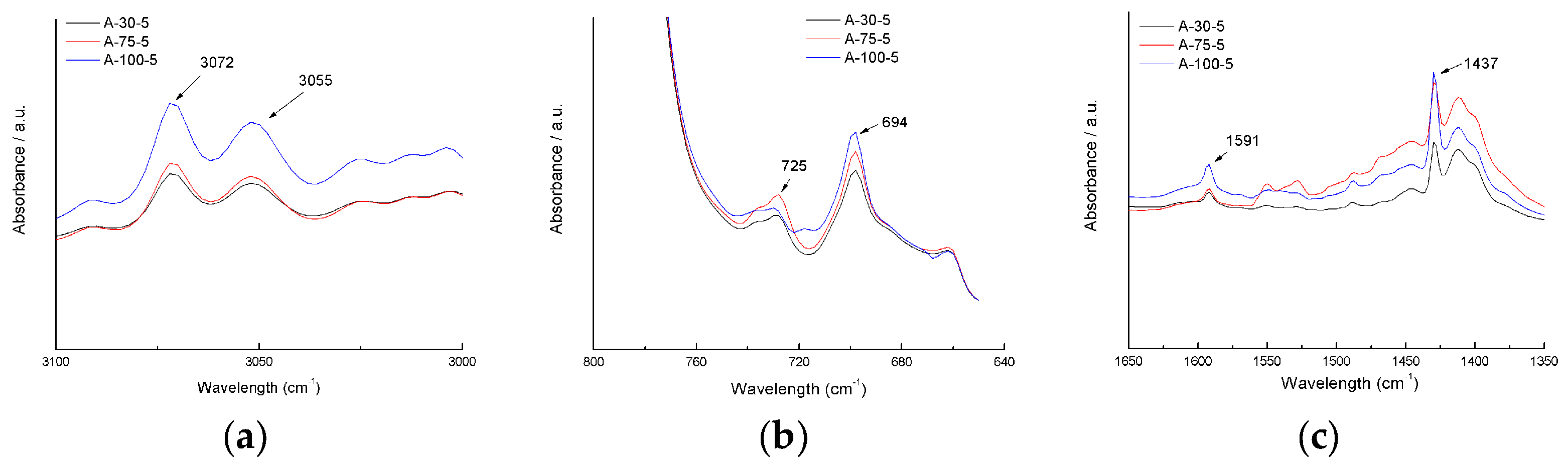
Determining the water contact angles and surface free energies can provide essential information on the surface properties of the coatings. Table 2 showed the contact angle results and calculated surface free energies of the coatings. As observed from Table 2, the water contact angles increased with the increase of the PSO content and viscosity. Meanwhile, PSO incorporated into the coatings also decreased the surface free energies of the coatings, which were calculated by the Owens two-liquid method. However, unlike the change in water contact angle, the effect of low viscosity PSO on the reduction of the surface free energies was more obvious. In terms of the functional group, the hydrophobicity of the phenyl group is better than that of the methyl group. Therefore, the addition of PSO enhanced the hydrophobicity of the coatings. Results also revealed the change of the chemical composition of the coatings with the incorporation of PSO. The more phenyl groups in the coating, the stronger the hydrophobicity of the coating. The FTIR results (Figure 1) also revealed that the strength of the featured absorption peaks of the phenyl group in coatings increased by increasing the viscosity of the PSO, indicating that the increase in the water contact angle (the featured absorption peak at 725 cm−1 was interfered by the featured absorption peak of Si–CH3 at 790 cm−1). Related studies also showed that the surface free energies of the PSO (7–100 mm2/s) were about 22.2 to 24.1 mJ/m2 [30]. Thus, low-viscosity PSO could significantly reduce the surface free energies of the coatings.
3.2. Mechanical Properties of the Coatings
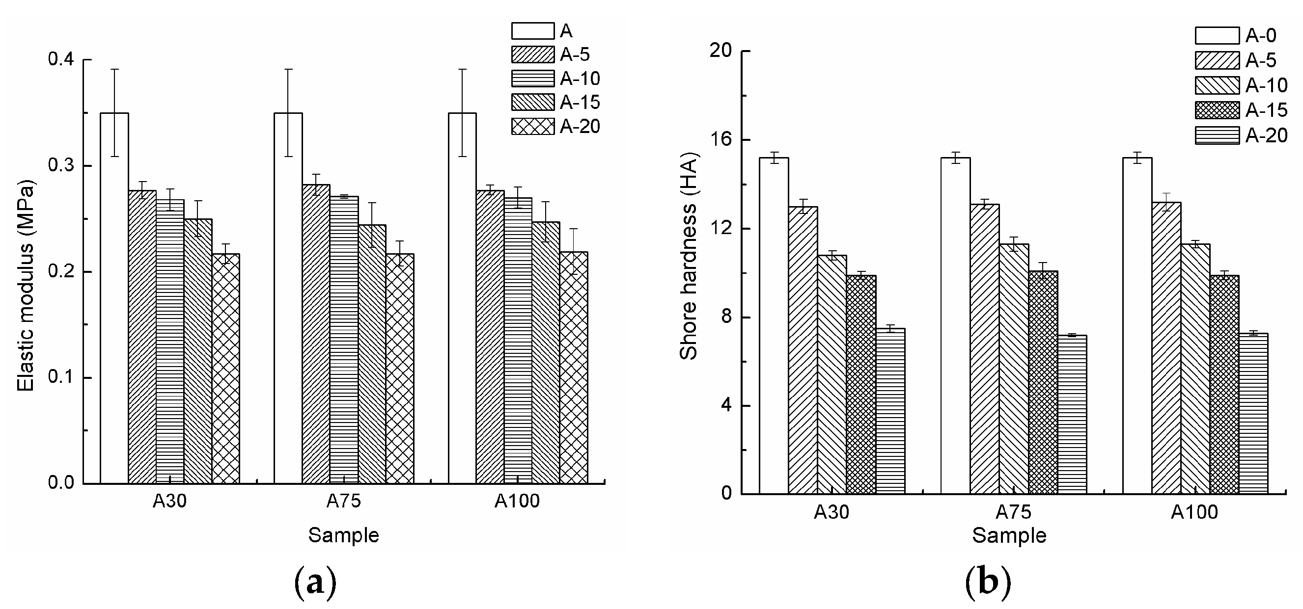
The mechanical properties of the coatings were evaluated via tensile test. The fitting elastic modulus and the measured shore hardness are presented in Figure 2. Experimental determination showed that the elastic modulus and the shore hardness decreased with the increase of the PSO content. For the coatings with different viscosity of the PSO, these properties were basically the same. The tensile curve of the sample is also shown in Figure 3. The tensile curves of the coatings with different viscosities of PSO were basically coincident under the same additive amount. By increasing the content of the PSO, the stress of the coating decreased at the same strain. This result was in agreement with the results of Truby [25]. In order to analyze the reason for the decrease of the mechanical properties of the coating, the crosslink density of the coating was measured. Crosslink density is defined as the moles of effective network chain per cubic centimeter [29]. The crosslink density of a polymer is an important parameter affecting its mechanical properties. Polymer with high crosslink density has better mechanical properties. Generally, it can be expressed by the number average molecular weight between two adjacent crosslinks (MC), and a larger value of MC indicates a lower polymer crosslink density [31,32]. For this experiment, the MC value of the coating is shown in Table 3. It is indicated that the value of MC increased with the increase of the PSO content, revealing the decrease of the crosslink density. The results also showed that the changing of the PSO viscosity did not change the crosslink density of the coatings. Non-reactive PSO was stored in the gap between the molecular chains of the coating, reducing the density of the polymer network chain. Therefore, the crosslink density of the coating was decreased. In general, the PSO with low molecular weight and high additive amount could have a more pronounced effect. The relative molecular mass of the PSO is shown in Table 1. Although the three kinds of PSO had different relative molecular weights, the difference of the relative molecular weight between the PSOs could be ignored compared with the relative molecular weight of the PDMS resin. Therefore, the viscosity of the PSO had little effect on the mechanical properties of the coatings, while the effect of the PSO content on the mechanical properties was more obvious. With the increase of the PSO content, the crosslink density of the coatings decreased, causing the decrease of the mechanical properties.
3.3. Leaching Observation of PSO
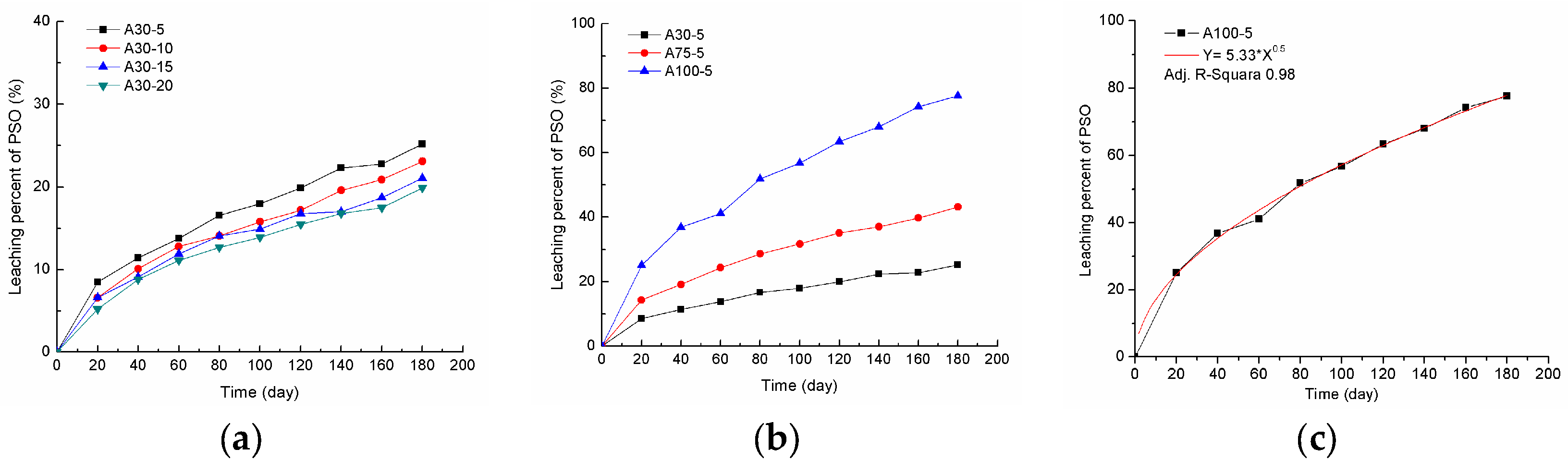
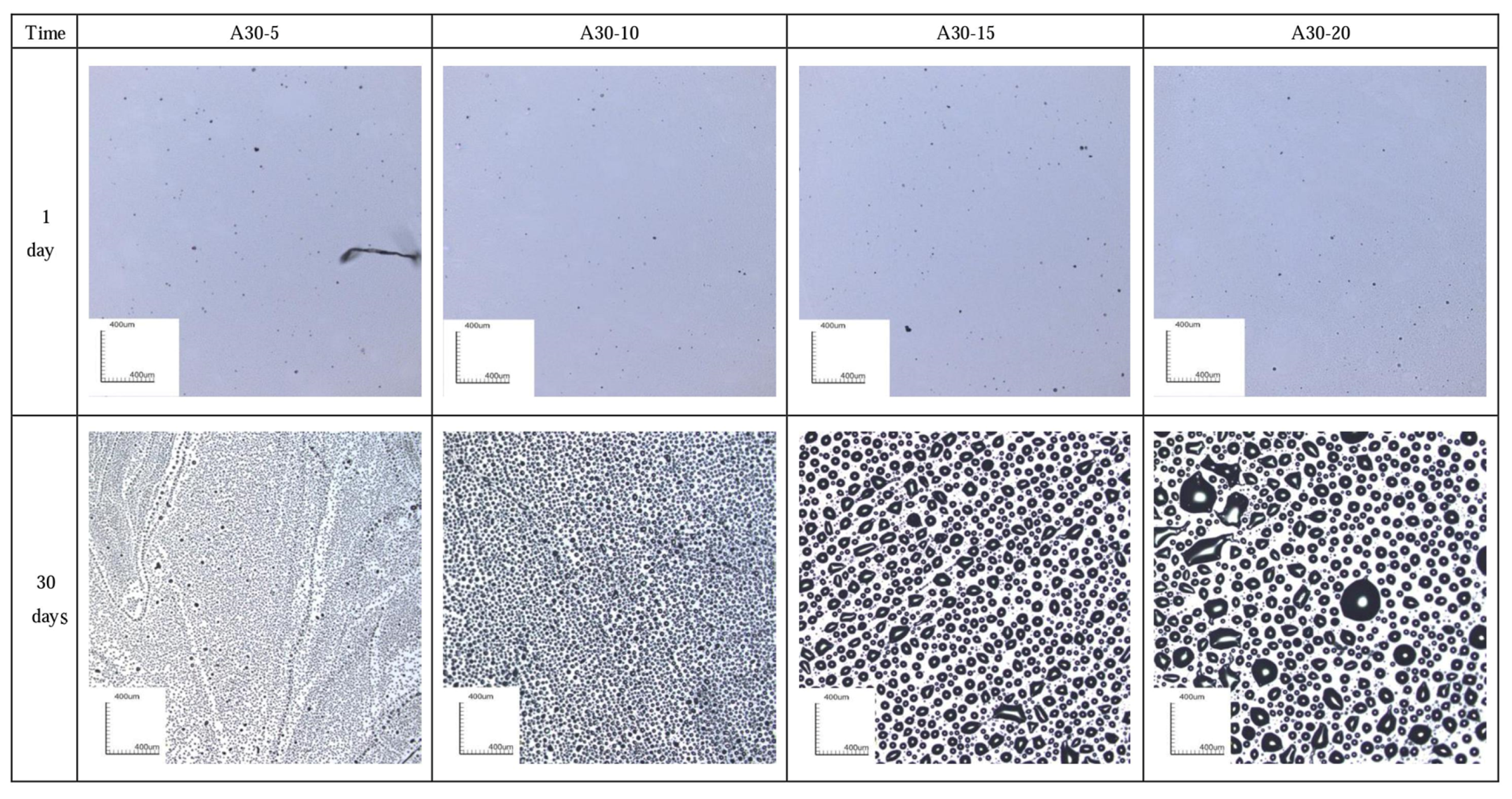
Samples with dimensions of 150 mm × 150 mm × 2 mm were used to observe the leaching of the PSO. The morphology of the sample is shown in Figure 4 and Figure 5 with 1 day and 30 days of exposure. After 1 day of exposure, no PSO was leached on the coating surface. With the extension of exposure time, PSO was gradually leached. It was also shown that the coating incorporating high viscosity and high additive amount of the PSO leached more PSO in the same amount of time. The leaching percent–time curve is shown in Figure 6. It basically follows the Higuchi diffusion equation (Figure 6c). By fitting the curve, the time needed for the complete leaching of the PSO could be simulated (Table 4). Although the increase of the PSO content resulted in the increase in the leaching amount of the PSO from the coatings at the same elapsed time, it also showed that the leaching percent of the PSO decreased with increasing PSO content. Coatings with low-viscosity PSO had a longer release time. For the coating A30-20, the time required for the complete leaching of the PSO exceeded 5890 days. In contrast, the coating of A100-5 released all the PSO in only 350 days.
Studies [5,20,21,22] on the incorporation of silicone oil into the fouling release coatings show that the reason for the leaching behavior of silicone oil from the coatings was the compatibility difference between silicone oil and the coatings, and note that compatibility should be characterized by a reasonable parameter. The leaching phenomenon can be considered as the phase separation of silicone oil and the coatings. Correspondingly, the Flory–Huggins interaction parameter (χ) between the coating A and the PSO is shown in Table 5. With the increase of the PSO viscosity, the value of χ increased. The high viscosity of the PSO contained more phenyl groups (Figure 1). This would lead to the increase in the molecular structure difference between the coating and the PSO. Therefore, with the increase of the PSO viscosity, the compatibility between the PSO and the coating decreased, causing more obvious leaching behavior of the PSO from the coatings. In addition, with the increase of the PSO content, the crosslink density of the coating decreased. The decrease of the crosslink density caused the decrease of the resistance to PSO leaching. Therefore, the PSO from the coatings with low crosslink density could be leached easily. This revealed that the leaching amount of the PSO was affected by the Flory–Huggins interaction parameter (χ) between the coating and the PSO, as well as the crosslink density of the coating. Although the leaching amount of the PSO at the same time increased, the increase of the PSO content eventually resulted in the decrease of the PSO leaching percent at the same time.
3.4. Benthic Diatom Adhesion Tests
The antifouling performance of the coatings was examined by conducting benthic diatom adhesion tests, and the results on the coating samples in the stage without leached PSO are shown in Table 6. The coatings incorporated with high-viscosity PSO had lower chlorophyll-a concentration, suggesting low levels of benthic diatom adhesion and high levels of the antifouling property. With the increase of the PSO content, the fouling removal rate of the coating increased. For the fouling release coating based on PDMS, the coating with high hydrophobicity showed a good ability to inhibit the adhesion of fouling organisms [1,3]. In addition, the low elastic modulus could effectively reduce the energy consumption required for the removal of fouling organisms, increasing the fouling removal rate of the coating [8]. The effect of the incorporation of PSO on the hydrophobicity and the elastic modulus of the coating was analyzed as above. Accordingly, the improvement of the antifouling performance of the coating could also be demonstrated by benthic diatom adhesion tests. The coating with high PSO content exhibited better hydrophobicity and lower elastic modulus, reducing the adhesion amount of benthic diatoms and increasing the fouling removal rate. Therefore, the corresponding antifouling performance was enhanced.
Subsequently, the antifouling performance of the coatings in the stage with leached PSO was also examined. The pretreatment ensured that there was no leached PSO on the surface of experimental samples. However, the leaching of the PSO was a continuous process, and PSO could still be released in fresh benthic diatom suspension. The experimental results are shown in Table 7. Comparison of Table 6 and Table 7 indicated that the concentration of chlorophyll-a for rinsed samples in the different stages were basically the same; however, the concentration of chlorophyll-a for washed samples in the stage with the leached PSO decreased obviously, meaning better antifouling performance. Further, the removal rate of samples in the stage with the leached PSO generally increased, and the values of some samples exceeded 90%. With the leaching of the PSO, the removal of fouling organisms was not only dependent on the elastic modulus of the coatings. The leaching PSO formed continuous oil films to block the adhesion of the benthic diatom to samples, or reduced the adhesion strength between the benthic diatom and the sample surface [22,23]. After washing, most of the benthic diatoms were removed. Section 3.3 showed that the coating with high PSO viscosity and high PSO content could leach more PSO in the same time, while it also showed that the coatings with high leached PSO could exhibit high levels of the removal rate. Therefore, benthic diatom adhesion tests of the coating indicated that the enhancement of the coating hydrophobicity effectively inhibited the adhesion of fouling organisms. In addition, the decrease of the elastic modulus of the coating as well as the PSO leached onto the coating surface increased the removal rate of the coating. The cause of this phenomenon was due to the incorporation of PSO.
4. Conclusions
This research investigated the influence of PSO with different viscosity and content on the antifouling performance of fouling release coatings based on PDMS. With the incorporation of PSO, the hydrophobicity of the coating was enhanced, and the mechanical properties of the coating, especially the elastic modulus, decreased. The leaching behavior of the PSO also indicated that the PSO with high viscosity and large content was more easily leached. By fitting the leaching percent–time curve of PSO, the leaching cycle of PSO could be correctly predicted. Due to the incorporation of PSO, the change of the above properties improved the antifouling performance of the coating. Therefore, the coating showed a low adhesion of the benthic diatom. The higher viscosity and the greater the content of PSO incorporated in the coating, the better the antifouling performance of the coating.
Author Contributions
Miao Ba, Zhanping Zhang, and Yuhong Qi designed and performed the experiments; Miao Ba and Zhanping Zhang analyzed the data; Zhanping Zhang and Yuhong Qi contributed reagents/materials/analysis tools; Miao Ba and Zhanping Zhang wrote the paper.
Acknowledgments
This work was supported by the National Natural Science Foundation of China (51079011, 51179018), the application basic research fund of the Ministry of Transport (2013329225330). The authors gratefully acknowledge for financial support.
Conflicts of Interest
The authors declare no conflict of interest.
References
- Callow, J.A.; Callwo, M.E. Trends in the development of environmentally friendly fouling-resistant marine coatings. Nat. Commun. 2011, 2, 244. [Google Scholar] [CrossRef] [PubMed]
- Chen, R.R.; Li, Y.K.; Tang, L.; Yang, H.C.; Lu, Z.T.; Wang, J.; Liu, L.H.; Takahashi, K. Synthesis of zinc-based acrylate copolymers and their marine antifouling application. RSC Adv. 2017, 7, 40020–40027. [Google Scholar] [CrossRef]
- Yang, W.J.; Neoh, L.G.; Kang, E.T.; Teo, L.M.; Rittschof, D. Polymer brush coatings for combating marine biofouling. Prog. Polym. Sci. 2014, 39, 1017–1042. [Google Scholar] [CrossRef]
- Nurioglu, A.G.; Esteves, A.C.C.; de With, G. Non-toxic, nonbiocide-release antifouling coatings based on molecular structure design for marine applications. J. Mater. Chem. B 2015, 3, 6547–6570. [Google Scholar] [CrossRef]
- Krishnan, S.; Weinman, C.J.; Ober, C.K. Advances in polymers for anti-biofouling surfaces. J. Mater. Chem. 2008, 18, 3405–3413. [Google Scholar] [CrossRef]
- Stafslien, S.J.; Christianson, D.; Daniels, J.; VanderWal, L.; Chernykh, A.; Chisholm, B.J. Combinatorial materials research applied to the development of new surface coatings XVI: Fouling-release properties of amphiphilic polysiloxane coatings. Biofouling 2015, 31, 135–149. [Google Scholar] [CrossRef] [PubMed]
- Loriot, M.; Linossier, I.; Vallee-Rehel, K.; Fay, F. Influence of biodegradable polymer properties on antifouling paints activity. Polymers 2017, 9, 36. [Google Scholar] [CrossRef]
- Hellio, C.; Yebra, D.M. Advances in Marine Antifouling Coatings and Technologies; Woodhead Publishing Ltd.: Cambridge, UK, 2009; pp. 1–15. [Google Scholar]
- Voulvoulis, N.; Scrimshaw, M.D.; Lester, J.N. Alternative antifouling biocides. Appl. Organomet. Chem. 1999, 13, 135–143. [Google Scholar] [CrossRef]
- Omae, I. General aspects of tin-free antifouling paints. Chem. Rev. 2003, 103, 3431–3448. [Google Scholar] [CrossRef] [PubMed]
- Matyjaszewski, K.; Tsarevsky, N.V. Nanostructured functional materials prepared by atom transfer radical polymerization. Nat. Chem. 2009, 1, 276–288. [Google Scholar] [CrossRef] [PubMed]
- Chambers, L.D.; Stokes, K.R.; Walsh, F.C.; Wood, R.J.K. Modern approaches to marine antifouling coatings. Surf. Coat. Technol. 2006, 201, 3642–3652. [Google Scholar] [CrossRef]
- Lejars, M.; Margillan, A.; Bressy, C. Fouling release coatings: A nontoxic alternative to biocidal antifouling coatings. Chem. Rev. 2012, 112, 4347–4390. [Google Scholar] [CrossRef] [PubMed]
- Heilen, W. Silicone Resins and Their Combinations; Vincentz Network GmbH & Co.: Hannover, Germany, 2005; p. 28. [Google Scholar]
- Buyl, F.D. Silicone sealants and structural adhesives. Int. J. Adhes. Adhes. 2001, 21, 411–422. [Google Scholar] [CrossRef]
- Patwardhan, S.V.; Taori, B.P.; Hassan, M.; Agashe, N.R.; Franklin, J.E.; Beaucage, G.; Mark, J.E.; Clarson, S.J. An investigation of the properties of poly(dimethylsiloxane)-bioinspired silica hybrids. Eur. Polym. J. 2006, 42, 167–178. [Google Scholar] [CrossRef]
- Eduok, U.; Faye, O.; Szpunar, J. Recent developments and applications of protective silicone coatings: A review of PDMS functional materials. Prog. Prg. Coat. 2017, 111, 124–163. [Google Scholar] [CrossRef]
- Mueller, W.J.; Nowacki, L.J. Ship’s Hull Coated with Antifouling Silicone Rubber. U.S. Patent 3,702,778, 14 November 1972. [Google Scholar]
- Selvig, T.A.; Leavitt, R.I.; Powers, W.P. Anti-Fouling Marine Compositions. U.S. Patent 4,025,693, 24 May 1977. [Google Scholar]
- Shivapooja, P.; Cao, C.Y.; Orihuela, B.; Levering, V.; Zhao, X.H.; Rittschof, D.; Lopez, G.P. Incorporation of silicone oil into elastomers enhances barnacle detachment by active surface strain. Biofouling 2016, 32, 1017–1028. [Google Scholar] [CrossRef] [PubMed]
- Howell, C.; Vu, T.L.; Lin, J.J.; Kolle, S.; Juthani, N.; Watson, E.; Weaver, J.C.; Alvarenga, J.; Aizenberg, J. Self-replenishing vascularized fouling-release surfaces. ACS Appl. Mater. Interfaces 2014, 6, 13299–13307. [Google Scholar] [CrossRef] [PubMed]
- Galhenage, T.P.; Hoffman, D.; Silbert, S.D.; Stafslien, S.J.; Daniels, J.; Milikovic, T.; Finlay, J.A.; Franco, S.C.; Clare, A.S.; Nedved, B.T.; et al. Fouling-release performance of silicone oil-modified siloxane-polyurethane coatings. ACS Appl. Mater. Interfaces 2016, 8, 29025–29036. [Google Scholar] [CrossRef] [PubMed]
- Stein, J.; Truby, K.; Wood, C.D.; Stein, J.; Gardner, M.; Swain, G.; Kavanagh, C.; Kovach, B.; Schultz, M.; Wiebe, D.; et al. Silicone foul release coatings: Effect of the interaction of oil and coating functionalities on the magnitude of macrofouling attachment strengths. Biofouling 2003, 19, 71–82. [Google Scholar] [CrossRef] [PubMed]
- Ware, C.S.; Smith-Palmer, T.; Peppou-Chapman, S.; Scarratt, L.R.; Humphries, E.M.; Balzer, D.; Neto, C. Marine antifouling behavior of lubricant-infused nanowrinkled polymeric surfaces. ACS Appl. Mater. Interfaces 2018, 10, 4173–7182. [Google Scholar] [CrossRef] [PubMed]
- Truby, K.; Wood, C.D.; Stein, J.; Cella, J.; Carpenter, J.; Kavanagh, C.; Swain, G.; Wiebe, D.; Lapota, D.; Meyer, A.; et al. Evaluation of the performance enhancement of the silicone biofouling-release coatings by oil incorporation. Biofouling 2000, 15, 141–150. [Google Scholar] [CrossRef] [PubMed]
- Afsar, A.; De Nys, R.; Steinberg, P. The effect of foul-release coatings on the settlement and behavior of cyprid larvae of the barnacle balanus amphitrite darwin. Biofouling 2003, 19, 105–110. [Google Scholar] [CrossRef] [PubMed]
- Owens, D.K.; Wendt, R.C. Estimation of the surface free energy of polymers. J. Appl. Polym. Sci. 1969, 13, 1741–1747. [Google Scholar] [CrossRef]
- Ba, M.; Zhang, Z.P.; Qi, Y.H. The dispersion tolerance of micro/nano particle in polydimethylsiloxane and its influence on the properties of fouling release coatings based on polydimethylsiloxane. Coatings 2017, 7, 107. [Google Scholar] [CrossRef]
- Jain, S.R.; Sekkar, V.; Krishnamurthy, V.N. Mechanical and swelling properties of HTPB-based copolyurethan networks. J. Appl. Polym. Sci. 1993, 48, 1515–1523. [Google Scholar] [CrossRef]
- Lai, G.Q.; Xin, S.M. Synthetic Process and Application of Organosilicon; Chemical Industry Press: Beijing, China, 2010; p. 420. (In Chinese) [Google Scholar]
- Flory, P.J.; Rehner, J.J. Statistical mechanics of cross-linked polymer networks II. swelling. J. Chem. Phys. 1943, 11, 521–526. [Google Scholar] [CrossRef]
- Oikawa, H.; Murakami, K. Some comments on the swelling mechanism of rubber vulcanizates. Rubber Chem. Technol. 1987, 60, 579–590. [Google Scholar] [CrossRef]
Figure 1.
Fourier transform infrared (FTIR) spectra of the phenyl group in coating samples: (a) the stretching vibration peaks of =C–H in the phenyl group at 3072 and 3055 cm−1; (b) the out-of-plane bending vibration peaks of =C–H in the phenyl group at 725 and 694 cm−1; (c) the stretching vibration peaks of C=C in the phenyl group at 1591 and 1488 cm−1.

Figure 2.
The mechanical properties of coating samples: (a) elastic modulus; (b) shore hardness.

Figure 3.
The tensile stress of samples (a) with different phenylmethylsilicone oil (PSO) viscosities and (b) with different additive amounts of PSO (Si-100).
Figure 3.
The tensile stress of samples (a) with different phenylmethylsilicone oil (PSO) viscosities and (b) with different additive amounts of PSO (Si-100).
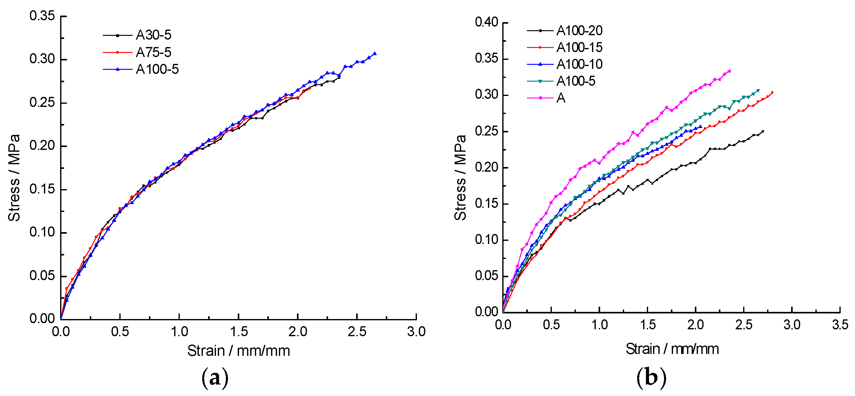
Figure 4.
Morphologies of different amounts of PSO leached on samples.

Figure 5.
Morphologies of different viscosities of PSO leached on samples.
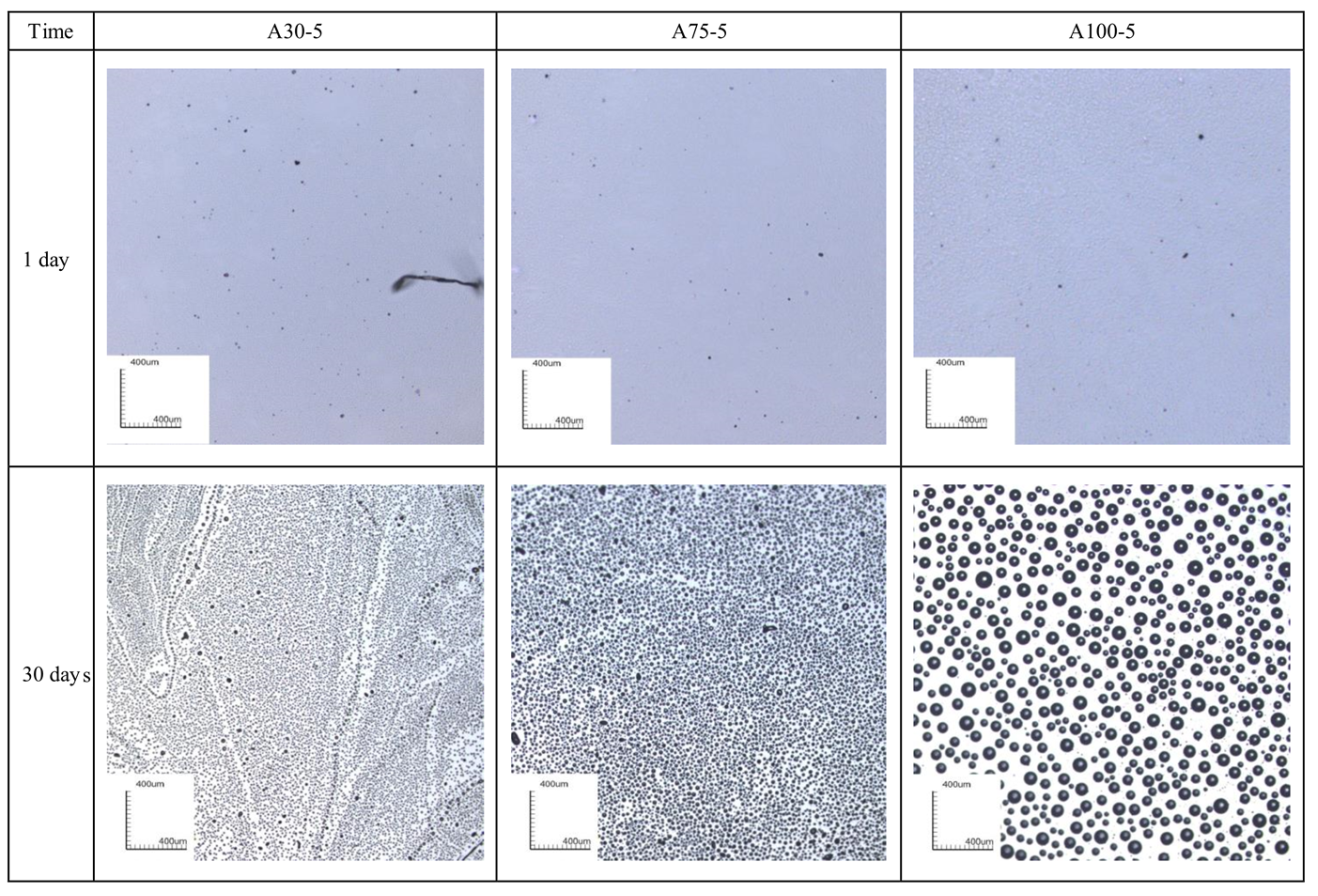
Figure 6.
The leaching percent–time curve: (a) with different viscosities of PSO; (b) with different PSO contents; (c) Higuchi fitting curve of A100-5.
Figure 6.
The leaching percent–time curve: (a) with different viscosities of PSO; (b) with different PSO contents; (c) Higuchi fitting curve of A100-5.

Table 1.
The density and the relative molecular mass of experimental materials. PDMS: polydimethylsiloxane.
Table 1.
The density and the relative molecular mass of experimental materials. PDMS: polydimethylsiloxane.
| Materials | Coating A | Si-30 | Si-75 | Si-100 | PDMS Resin |
|---|---|---|---|---|---|
| Density (g/cm3) | 0.975 | 0.996 | 1.001 | 1.007 | - |
| Relative molecular mass | - | 450 | 610 | 700 | 60,000 |
Table 2.
The contact angle and surface free energies of coating samples (±SEM (standard error of the mean), n = 6).
Table 2.
The contact angle and surface free energies of coating samples (±SEM (standard error of the mean), n = 6).
| Sample | Contact Angle (°) | Surface Free Energy (mJ/m2) | |
|---|---|---|---|
| Water | Diiodomethane | ||
| A | 107.1 ± 0.31 | 65.4 ± 0.11 | 25.8 ± 0.41 |
| A30-5 | 113.9 ± 0.23 | 73.4 ± 0.27 | 21.6 ± 0.22 |
| A30-10 | 114.7 ± 0.17 | 74.3 ± 0.31 | 21.1 ± 0.18 |
| A30-15 | 115.3 ± 0.08 | 75.3 ± 0.28 | 20.6 ± 0.33 |
| A30-20 | 116.0 ± 0.22 | 76.5 ± 0.21 | 19.9 ± 0.28 |
| A75-20 | 116.9 ± 0.15 | 72.1 ± 0.21 | 22.9 ± 0.19 |
| A100-20 | 118.5 ± 0.44 | 70.7 ± 0.33 | 24.2 ± 0.38 |
Table 3.
The MC value of samples. (±SEM, n = 6).
| Sample | A | A30-5 | A30-10 | A30-15 | A30-20 | A75-20 | A100-20 |
|---|---|---|---|---|---|---|---|
| MC | 11,728 ± 246 | 19,840 ± 374 | 22,495 ± 277 | 24,336 ± 406 | 32,799 ± 178 | 32,710 ± 323 | 32,706 ± 301 |
Table 4.
The estimated time for leaching PSO completely.
| Sample | A30-5 | A30-10 | A30-15 | A30-20 | A75-5 | A100-5 |
|---|---|---|---|---|---|---|
| Time (day) | 2250 | 3810 | 5000 | 5890 | 760 | 350 |
Table 5.
Flory–Huggins interaction parameter between samples and PSO. (±SEM, n = 6).
| Materials | Si-30 | Si-75 | Si-100 |
|---|---|---|---|
| χ | 1.037 ± 0.0297 | 1.434 ± 0.0266 | 1.779 ± 0.0177 |
Table 6.
Experimental results of the benthic diatom adhesion test on the stage of no leaching of PSO. (±SEM, n = 3).
Table 6.
Experimental results of the benthic diatom adhesion test on the stage of no leaching of PSO. (±SEM, n = 3).
| Sample | A | A30-5 | A75-5 | A100-5 | A100-10 | A100-15 | A100-20 |
|---|---|---|---|---|---|---|---|
| Concentration of chlorophyll-a for rinsed samples (mg/m2) | 1735 ± 56 | 1567 ± 27 | 1445 ± 19 | 1375 ± 28 | 830 ± 23 | 719 ± 31 | 460 ± 12 |
| Concentration of chlorophyll-a for washed samples (mg/m2) | 747 ± 27 | 622 ± 42 | 565 ± 32 | 534 ± 28 | 273 ± 33 | 197 ± 40 | 106 ± 20 |
| Fouling removal rate (%) | 56.5 ± 4.71 | 60.3 ± 3.89 | 61.7 ± 2.77 | 60.9 ± 4.14 | 67.1 ± 1.80 | 72.6 ± 2.97 | 76.7 ± 4.36 |
Table 7.
Experimental results of the benthic diatom adhesion test on the stage of leaching of PSO. (±SEM, n = 3).
Table 7.
Experimental results of the benthic diatom adhesion test on the stage of leaching of PSO. (±SEM, n = 3).
| Sample | A | A30-5 | A75-5 | A100-5 | A100-10 | A100-15 | A100-20 |
|---|---|---|---|---|---|---|---|
| Concentration of chlorophyll-a for rinsed samples (mg/m2) | 1774 ± 48 | 1615 ± 37 | 1485 ± 22 | 1365 ± 42 | 847 ± 33 | 707 ± 12 | 471 ± 22 |
| Concentration of chlorophyll-a for washed samples (mg/m2) | 786 ± 41 | 326 ± 19 | 293 ± 43 | 205 ± 27 | 115 ± 19 | 66 ± 25 | 37 ± 15 |
| Fouling removal rate (%) | 55.7 ± 3.21 | 79.8 ± 3.11 | 80.3 ± 2.16 | 85.0 ± 5.10 | 86.4 ± 3.67 | 90.7 ± 2.77 | 92.1 ± 3.21 |
© 2018 by the authors. Licensee MDPI, Basel, Switzerland. This article is an open access article distributed under the terms and conditions of the Creative Commons Attribution (CC BY) license (http://creativecommons.org/licenses/by/4.0/).
Share and Cite
MDPI and ACS Style
Ba, M.; Zhang, Z.; Qi, Y. Fouling Release Coatings Based on Polydimethylsiloxane with the Incorporation of Phenylmethylsilicone Oil. Coatings 2018, 8, 153. https://doi.org/10.3390/coatings8050153
AMA Style
Ba M, Zhang Z, Qi Y. Fouling Release Coatings Based on Polydimethylsiloxane with the Incorporation of Phenylmethylsilicone Oil. Coatings. 2018; 8(5):153. https://doi.org/10.3390/coatings8050153
Chicago/Turabian StyleBa, Miao, Zhanping Zhang, and Yuhong Qi. 2018. "Fouling Release Coatings Based on Polydimethylsiloxane with the Incorporation of Phenylmethylsilicone Oil" Coatings 8, no. 5: 153. https://doi.org/10.3390/coatings8050153
Note that from the first issue of 2016, this journal uses article numbers instead of page numbers. See further details here.