Numerical Investigation of Film Cooling Enhancement Using an Upstream Sand-Dune-Shaped Ramp

College of Energy and Power Engineering, Jiangsu Province Key Laboratory of Aerospace Power System, Nanjing University of Aeronautics and Astronautics, Nanjing 210016, China
*
Author to whom correspondence should be addressed.
Computation 2018, 6(3), 49; https://doi.org/10.3390/computation6030049
Submission received: 6 August 2018
/
Revised: 24 August 2018
/
Accepted: 25 August 2018
/
Published: 4 September 2018
(This article belongs to the Special Issue Computational Heat, Mass and Momentum Transfer)
Abstract
:Film cooling enhancement by incorporating an upstream sand-dune-shaped ramp (SDSR) to the film hole exit was numerically investigated on a flat plate under typical blowing ratios ranging from 0.5 to 1.5. Three heights of SDSRs were designed: 0.25D, 0.5D, and 0.75D. The results indicated that the upstream SDSR effectively controlled the near-wall primary flow and subsequent mutual interaction with the coolant jet, which was the main mechanism of the film cooling enhancement. First, a pair of anti-kidney vortices was formed at the trailing ridges of the SDSR, which helped suppress the kidney vortex pair due to the interaction between the coolant jet and the primary flow. Second, a weak separation and a low pressure zone were induced behind the backside of the SDSR, which caused the coolant jet to spread around the film cooling hole and improve the lateral film coverage. With respect to the baseline cylindrical film cooling holes, the effect of the upstream SDSR was distinct under different blowing ratios. Under a low blowing ratio, the upstream SDSR shortened the streetwise film layer coverage in the vicinity of the film hole centerline but increased the span-wise film layer coverage. A relatively optimal ramp height seemed to be 0.5D. Under a high blowing ratio, both the streamwise and span-wise film layer coverages improved in comparison with the baseline case. The film cooling effectiveness improved gradually with increasing ramp height.
1. Introduction
Film cooling techniques play an important role in the thermal protection of hot turbine engine components, such as the blade, combustor liner, and exhaust nozzle. Because the cooling air for film cooling purposes is extracted from the compressor stage of the turbine engine, the use of the coolant undoubtedly results in engine performance implications. For this reason, the optimal design of the film cooling configuration is of primary concern to many researchers in the search for better film cooling effectiveness with less bleed air usage. In addition, the ever-increasing inlet temperature in next-generation gas turbines remains a challenge [1].
Over the past decades, considerable efforts had been devoted to film cooling enhancement. The most inspiring and remarkable advancement was the innovation of shaped holes created by incorporating exit shaping into the film cooling holes [2,3]. The use of shaped holes allowed the suppression of kidney vortices due to the mutual interaction between discrete coolant jets and primary flow. In addition to the shaped holes, researchers recently found that the upstream ramp played a role in anti-kidney vortices, which mitigated the mutual interaction between the coolant jet and the primary flow [4]. Barigozzi and colleagues [5,6] experimentally studied the effect of the upstream ramp on the aerodynamic losses and adiabatic effectiveness of both a cylindrical hole and a fan-shaped hole. Chen et al. [7] and Rallabandi et al. [8] studied the effects of an upstream ramp on film cooling performance, considering the ramp width, height, and upstream location. Yan et al. [9] experimentally investigated the combined effects of an upstream ramp and a swirling coolant flow on film cooling characteristics. Abdala and Elwekeel [10] and Abdala et al. [11] numerically investigated the influence of various upstream ramp shapes on film cooling performance. It was illustrated that a properly curved step produced a higher lateral film cooling effectiveness and a lower heat transfer coefficient in comparison to a normal step. Of particular interest was the novel Barchan-dune-shaped ramp proposed by Zhou and Hu [12,13]. These researchers found that the film cooling effectiveness over a test plate was significantly enhanced using the Barchan-dune-shaped ramp. At a low blowing ratio, a higher aerodynamic loss was produced in comparison with that produced with a conventional film cooling design. However, at relatively high blowing ratios, the use of Barchan-dune-shaped ramps was found to be beneficial for reducing aerodynamic loss, since the unique Barchan-dune-shaped ramp design kept the coolant flow attached more firmly to the protected surface.
As mentioned above, film cooling effectiveness can be enhanced using an upstream Barchan-dune-shaped ramp, but due to experiment limitations, the Barchan-dune-shaped ramp’s action mechanism in film cooling is currently not fully explained. Therefore, we performed a numerical simulation to obtain more insight into film cooling performance using an upstream Barchan-dune-shaped ramp. Particular attention was given to exploring the effect of ramp height under typical blowing ratios ranging from 0.5 to 1.5.
2. Numerical Modelling
2.1. Computational Domain
The baseline case was a flat plate with a row of cylindrical, inclined holes. One hole-to-hole pitch was selected as the computational domain, as shown in Figure 1. The computational domain was composed of three sub-zones: the primary flow passage, the film hole, and the coolant plenum. The film hole diameter (D) was 4 mm and the hole-to-hole pitch was 3D. The primary flow passage had a length of 45D and a height of 15D. The film hole was located 15D downstream of the primary flow passage inlet. The coordinate origin was located at the trailing edge of the film hole exit.
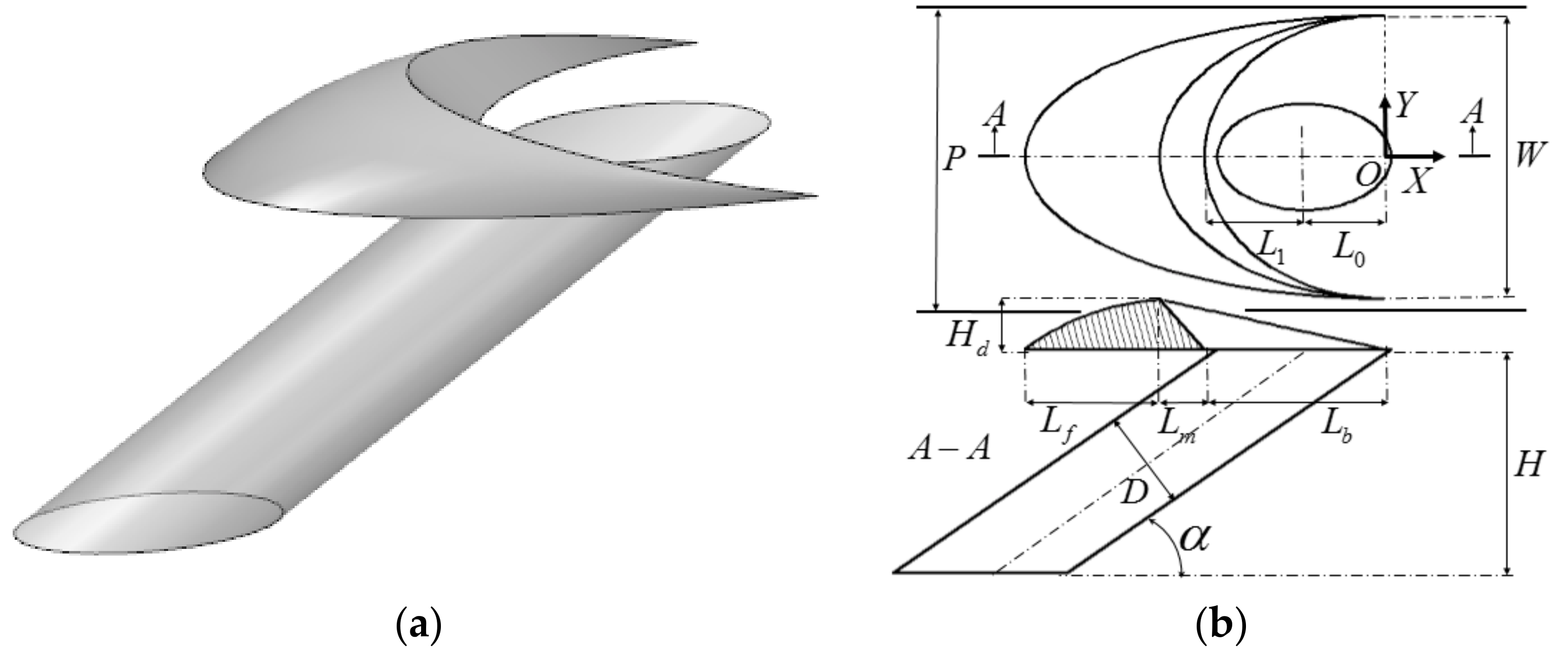
The inclination angle (α) of the film cooling hole was fixed at 35°. A sand-dune-shaped ramp was located upstream of the film hole exit. Figure 2a shows the schematic three-dimensional (3D) view of the sand-dune-shaped ramp (SDSR). The ramp height and length are denoted as Hd and Ld, respectively. The other geometric parameters are illustrated in Figure 2b and summarized in Table 1. The baseline case or the cylindrical hole is denoted as Case 1. Cases 2–4 refer to the cases with an upstream ramp with corresponding ramp heights of 0.25D, 0.5D, and 0.75D, respectively.
2.2. Boundary Conditions
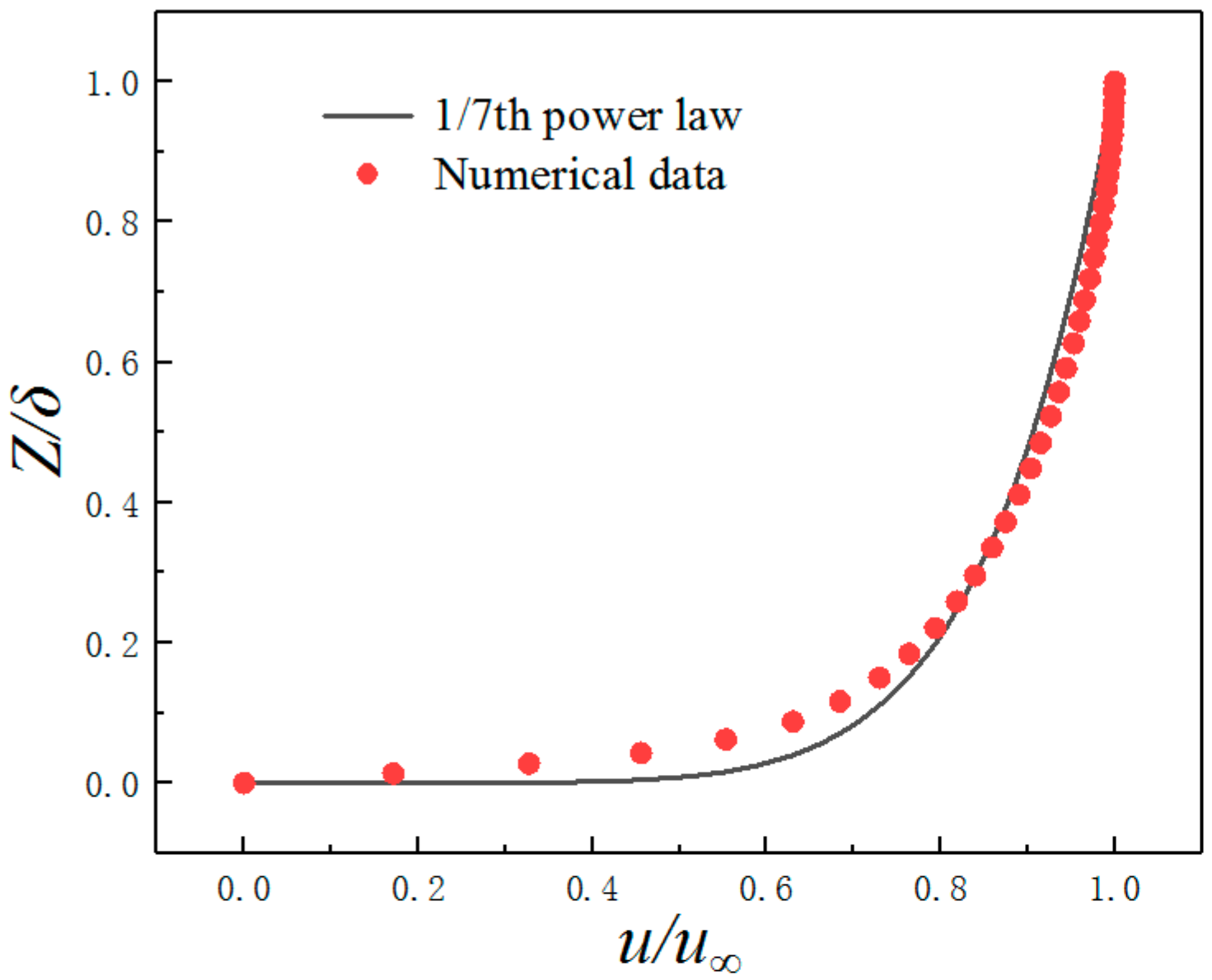
The boundary conditions at the secondary and primary flow inlets were both defined as velocity inlets, and the flow outlet condition was set as the pressure outlet. For the primary flow, the inlet was specified as a fully developed velocity profile (1/7th power law) as:
where the inlet boundary layer thickness δ was set to 1.4D, the inlet velocity u∞ was 25 m/s, the inlet temperature T∞ was 380 K, and the Reynolds number Rex was about 18,000 based on the distance between the mainstream inlet and the film hole. For the secondary flow, the temperature Tc was 300 K and the inlet velocity was calculated according to the blowing ratio (M). A turbulence intensity of 2% and a turbulence length scale of 3% inlet hydraulic diameter were used for the low-turbulence oncoming flow. The flow outlet was set as the pressure outlet with a static pressure of 101,325 Pa. Periodic conditions were applied for the two symmetric boundaries of the computational domain. For all solid walls, thermally adiabatic and no-slip conditions were used. The blowing ratio (M) is calculated as:
where ρc and uc are the density and velocity of the secondary flow or coolant flow at the inlet of film hole, respectively; and ρ∞ and u∞ are the density and velocity of the primary flow, respectively. Figure 3 shows the boundary layer velocity profile of the primary flow upstream of the hole exit. It can be found that the velocity profile is close to the 1/7th power law. The boundary layer thickness was found to be δ99 ≈ 1.2D, the displacement thickness δ* ≈ 0.18D, and the momentum thickness θ ≈ 0.134D. Therefore, the corresponding shape factor H12 was about 1.34 (normally for turbulence boundary layer: H12 ≈ 1.2–1.5). More information about the effects of boundary layer states on film cooling performance was reported previously [14,15].
2.3. Computational Scheme
Three-dimensional numerical simulation was employed using Fluent-CFD software. The second-order upwind scheme was used for the spatial discretization of convective terms in the conservation equations, and the SIMPLEC (semi-implicit method for pressure-linked equations, SMPLE consistent) algorithm was used for pressure-velocity coupling. Referring to previous investigations [16,17,18], the realizable k-ε turbulence model with the incorporation of enhanced wall treatment was used to model the turbulence characteristics. Convergence was achieved when both the following criteria were met: (1) reduction in all residuals of five orders of magnitude, and (2) the temperature change not exceeding ±0.1 K in local temperature prediction on the protected surface for an additional 30 iterations.
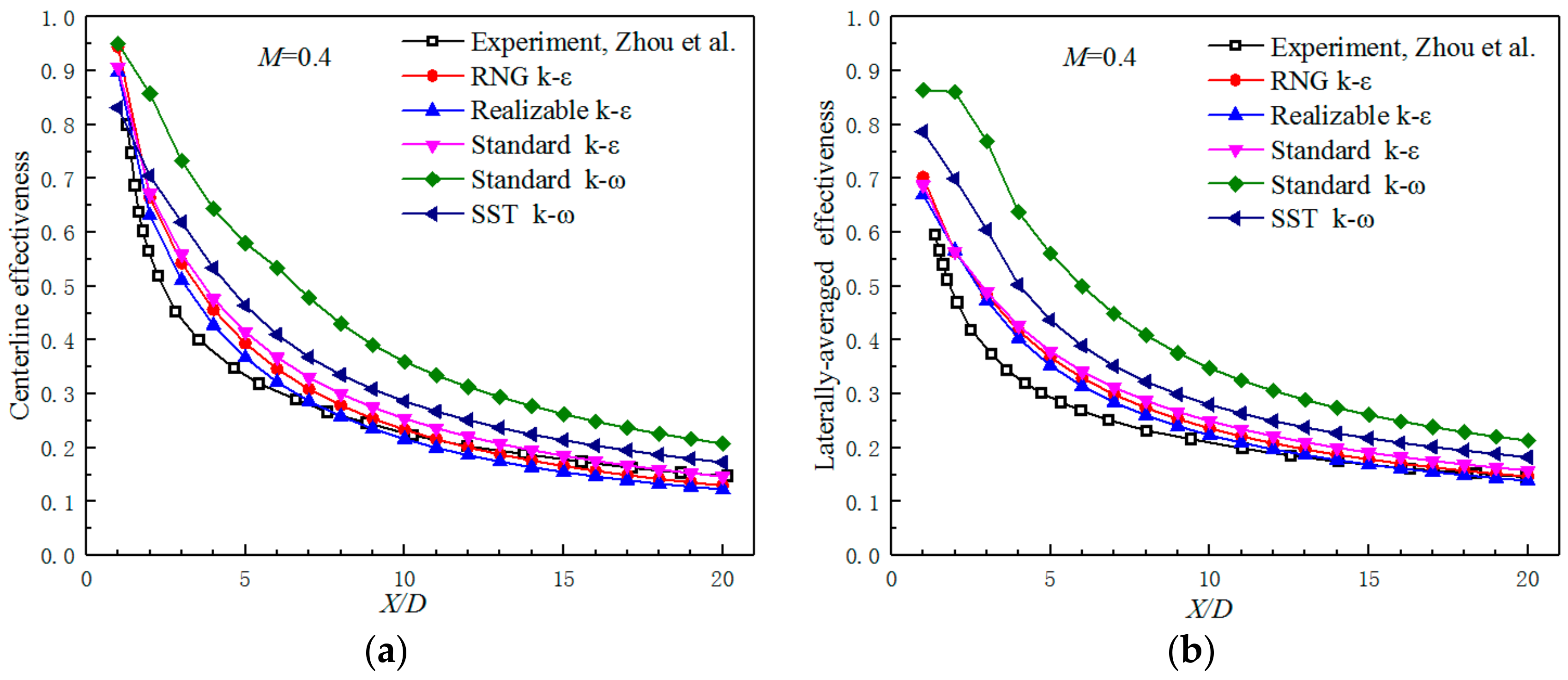
To validate the computational scheme, a series of numerical simulations with five two-equation RANS (Reynolds-averaged Navier-Stokes equations) solvers were performed, and the results were compared with the experimental data reported by Zhou et al. [12]. In order to ensure the comparability of the results, the computational model (Barchan-dune-shaped ramp, Hd = 0.5D) and boundary condition were consistent with the literature. As shown in Figure 4, among the five turbulence models, the result of the realizable k-ε turbulence model agreed the best with the experimental result in both centerline and laterally-averaged effectiveness. In general, the variation tendencies of the film cooling effectiveness for both the experiment case and the realizable k-ε turbulence model case were the same, and the maximum difference was about 10%. It is worth noting that there are some deficiencies in the numerical simulation that were reported by Nikparto et al. [19] and Nikparto et al. [20], but the RANs solver is still a good method for time saving and economy, and the prediction accuracy basically meets the requirements for flat plate film cooling when the turbulence model is reasonably selected.
Overall, multi-block grids were generated for the entire computational domain, as shown in Figure 5a. Hexahedral-structured grids were applied to both the primary flow channel and the secondary flow plenum. For the local computational zone in the vicinity of the ramp, tetrahedral unstructured grids were adopted. To achieve a grid-independent solution, three sample grid systems were designed, with total grid numbers of 1.1 million, 2.3 million, and 4.8 million respectively. Figure 5b presents the influence of grid number on the adiabatic film cooling effectiveness distribution at film hole centerline for typical conditions. As a consequence, a grid system with approximately 2.3 million grids was finally selected for the whole computational domain where the corresponding maximum Z+ (the Reynolds number based on friction velocity and wall normal distance) was about 0.95.
3. Results and Discussion
Two characteristic parameters were adopted to evaluate the film cooling performance: adiabatic film cooling effectiveness (ηad) and laterally-averaged adiabatic film cooling effectiveness (ηave):
where T∞ and Tc are the temperature of the primary flow and the cooling flow, respectively; and Taw and are the adiabatic wall temperature and the laterally-averaged adiabatic wall temperature, respectively.
3.1. Detailed Flow Fields
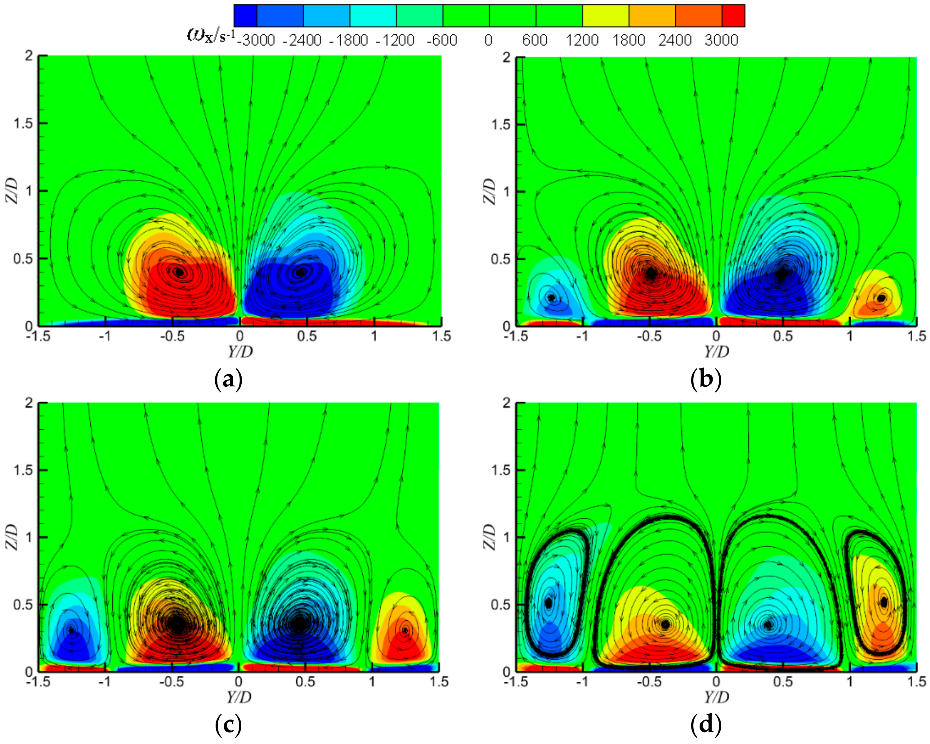
Figure 6 presents the streamwise vorticity distributions (ωx) and streamlines at a cross-sectional plane of x/D = 2 under M = 1.0. For the conventionally cylindrical hole (Case 1), the interaction between the coolant jet and primary flow results in the formation of kidney vortices, as seen in Figure 6a. These vortices are detrimental to film cooling because they lift the coolant jet off the protected surface and force the hot primary flow to enter beneath the coolant jet. The vortex cores are located at approximately Z = 0.4D in the normal direction. Once a sand-dune-shaped ramp is placed upstream of the film hole exit, an additional pair of vortices is produced at both sides of the kidney vortices, which rotate opposite related to the kidney vortices. This additional pair of vortices has an anti-kidney vortices role, compressing the size of the original kidney vortices, as seen in Figure 6a. With increasing ramp height, the size of the anti-kidney vortices increases, as seen in Figure 6b–d, reflecting that the formation of these anti-kidney vortices is associated with the contoured shape of the ramp. In view of the film cooling mechanism, the anti-kidney vortices help enhance the film cooling effectiveness.
Figure 7 presents the dimensionless temperature contours and streamlines on the film hole centerline plane under M = 1.0 for Cases 1 and 3. Here, the dimensionless temperature is defined as . In comparison with the baseline case (Case 1), a weak separation of the primary flow was found for Case 3 behind the rear face of the sand-dune-shaped ramp. In addition, the coolant jet penetration into the primary flow for Case 3 seemed to be less than that of Case 1. The cooling film coverage was also found to be adequate for Case 3.
Figure 8 presents the detailed flow fields in the vicinity of the film cooling hole exit for Case 4 under M = 1.0. The relative static pressure contours are displayed in Figure 8a on a horizontal plane (Z/D = 0.125) and Figure 8b displays a vertical plane (Y/D = 0). Behind the rear face of the sand-dune-shaped ramp, a relatively low static pressure is produced due to the weak separation of the primary flow. Owing to the above flow-filled features in the vicinity of the film cooling hole exit, the coolant jet ejecting from the film cooling hole could be partly entrained into this low static pressure zone, making the near-wall flow very complicated around the film hole exit, as illustrated in Figure 8c. The recirculating flow behind the rear face of the sand-dune-shaped ramp takes on a 3D screw-type nature. Originating from the recirculating zone, the streamlines are mainly divided into two parts. The streamlines in the middle region interact with the primary flow, forming the kidney vortices. The streamlines at the ramp-edge region mix with the primary flow to form the anti-kidney vortices at both sides of the kidney vortices. Obviously, the upstream ramp changes the near-wall primary flow and consequently, the mutual interaction between the coolant jet and the primary flow, resulting in coolant jet entrainment around the front edge of film hole exit and the formation of a pair of anti-kidney vortices downstream from the film hole exit.
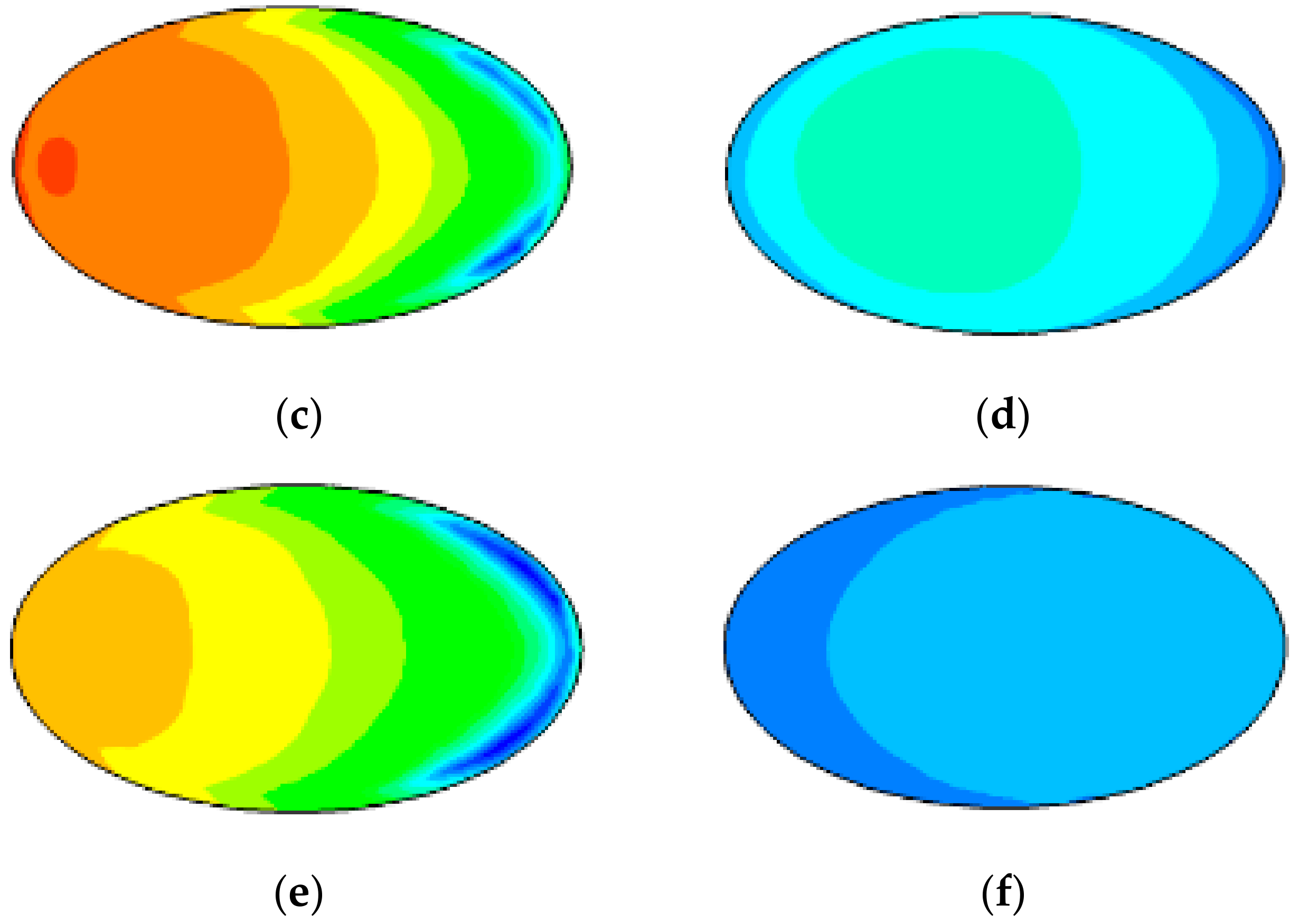
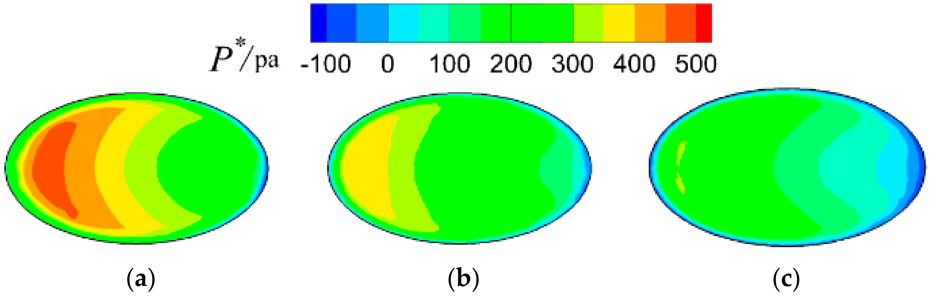
Figure 9 shows the relative static pressure contours on the hole entrance and exit under a blowing ratio of 1.0. For a cylindrical hole, the pressure distributions on the hole entrance and exit show the same feature: the static pressure decreases gradually from the left side to right side. For Cases 3 and 4, the pressures on the film hole entrance and exit are lower than in Case1 because a relative low pressure zone is created immediately downstream of the ramp, which reduces the hole-exit pressure, meaning that the hole-entrance pressure has to be lower under the same blowing ratio. The reduced pressure on the film hole entrance is good for reducing the cooling air supply pressure or providing more coolant with the same pressure. In addition, we found that the high-pressure core on the film hole exit gradually moves to the right side with the increase in ramp height, as seen as Figure 9b,d,f.
Figure 10 presents the total pressure contours on the film hole exit under M = 1.0 for Cases 1, 3, and 4. It can be clearly seen that the total pressure on the hole exit gradually decreases with increasing ramp height, which is why the coolant penetration into the mainstream is suppressed.
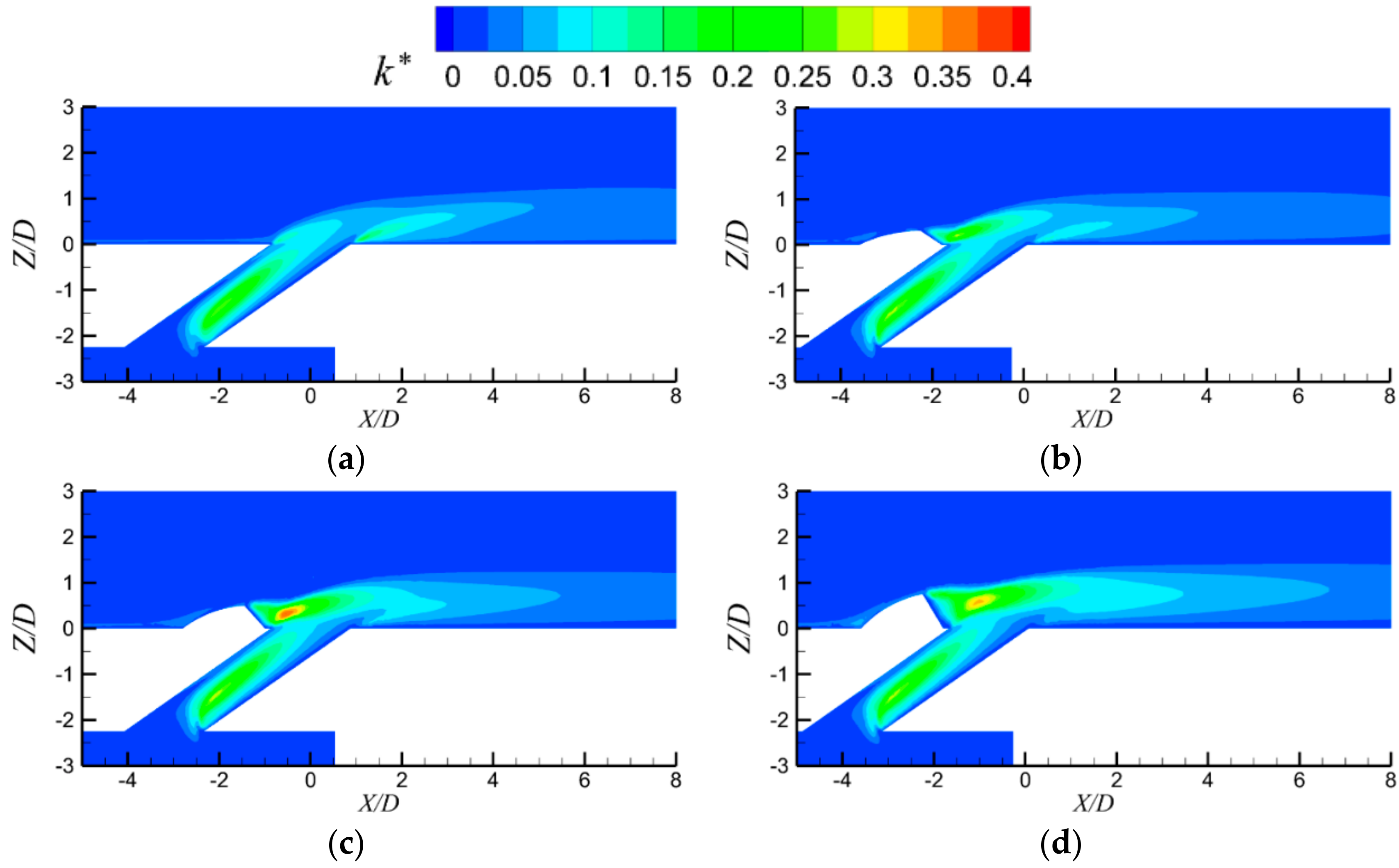
Figure 11 presents the non-dimensional turbulent kinetic energy contours on the hole centerline plane under M = 1.0. The non-dimensional turbulent kinetic energy is defined as , where k is the turbulent kinetic energy. By comparing the four pictures, we clearly observed that k* increased more or less when a SDSR appears in the flow field, especially in the immediate downstream of the ramp, which affects film cooling performance mainly in two aspects: (1) suctioning the coolant to cover a greater area and (2) producing additional mixing losses. For Case 2, k* increased only immediately downstream of the ramp because the ramp height was quite low (Hd = 0.25D), but with the increase in ramp height, more areas were affected.
3.2. Adiabatic Film Cooling Effectiveness
Figure 12, Figure 13 and Figure 14 present the detailed adiabatic film cooling effectiveness distributions under a low blowing ratio of M = 0.5, a moderate blowing ratio of M = 1.0, and a high blowing ratio of M = 1.5, respectively.
Under a low blowing ratio, as seen in Figure 12, the upstream sand-dune-shaped ramp significantly improved the lateral film cooling coverage around the film hole exit, which was obviously due to the coolant jet entrainment in this local zone. Immediately downstream of the film cooling hole, the lateral film cooling coverage was also improved by the upstream sand-dune-shaped ramp. With the increase in ramp height, the uniformity of the lateral film cooling coverage gradually improved but the streamwise development of the film layer in the vicinity of film hole centerline weakened. As the coolant jet momentum was low under a small blowing ratio, the strong spreading of the coolant jet near the film hole exit reduced its flow capacity along the streamwise direction.
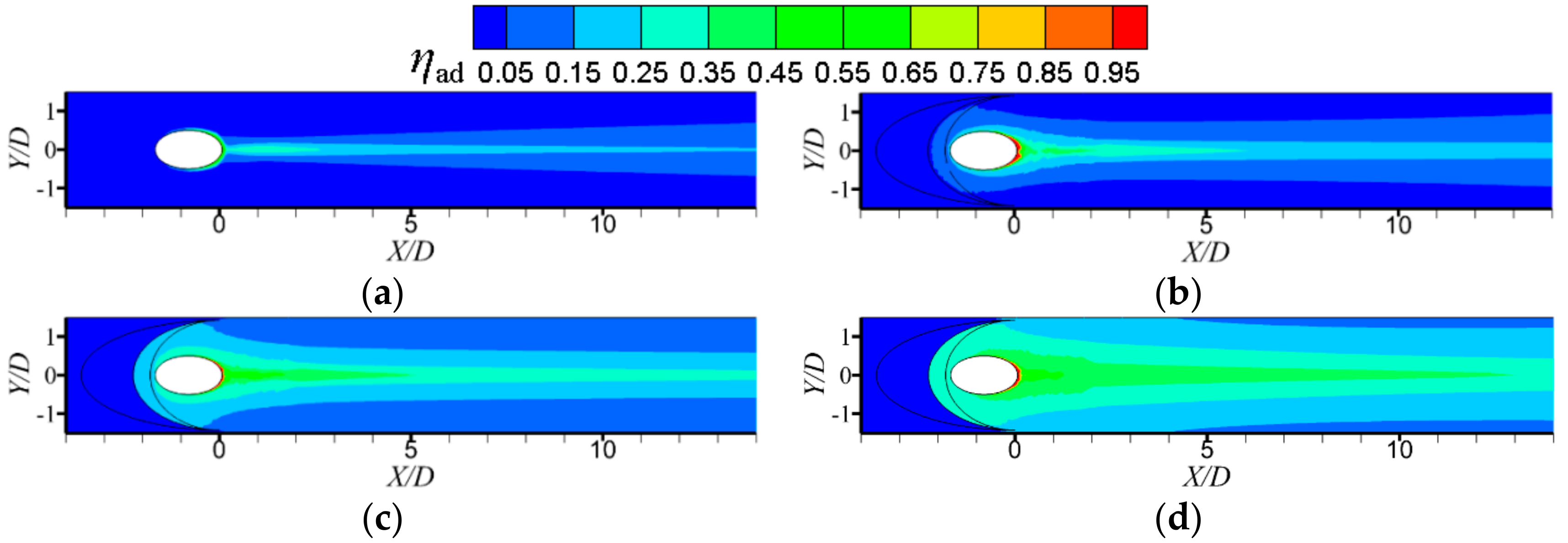
Under a moderate blowing ratio, as seen in Figure 13, the film cooling effectiveness for the baseline case reduced somewhat compared to that under a low blowing ratio. With increasing blowing ratio, the jet ejection momentum resulted in stronger jet penetration. Compared with the respective case under a low blowing ratio, we confirmed that the local film cooling effectiveness immediately downstream of the film cooling hole also reduced for the cases with an upstream ramp. However, the streamwise development of the film layer in the vicinity of the film hole centerline was enhanced, especially for the cases with greater ramp heights. As the coolant jet penetration was more effectively suppressed due to the role of the anti-kidney vortices of the upstream ramp, the coolant jet momentum was mainly transferred toward the streamwise direction.
Under a high blowing ratio, as seen in Figure 14, the film cooling effectiveness for the baseline case reduced tremendously compared to that under a low blowing ratio. Although the upstream sand-dune-shaped ramp shows its potential role in improving film cooling effectiveness relative to the baseline case, the local film cooling effectiveness was confirmed to be much less than the corresponding case under a low or moderate blowing ratio. Because the jet penetration was too strong under a high blowing ratio, the entrainment of the weak separation of the primary flow to the coolant jet certainly reduced.
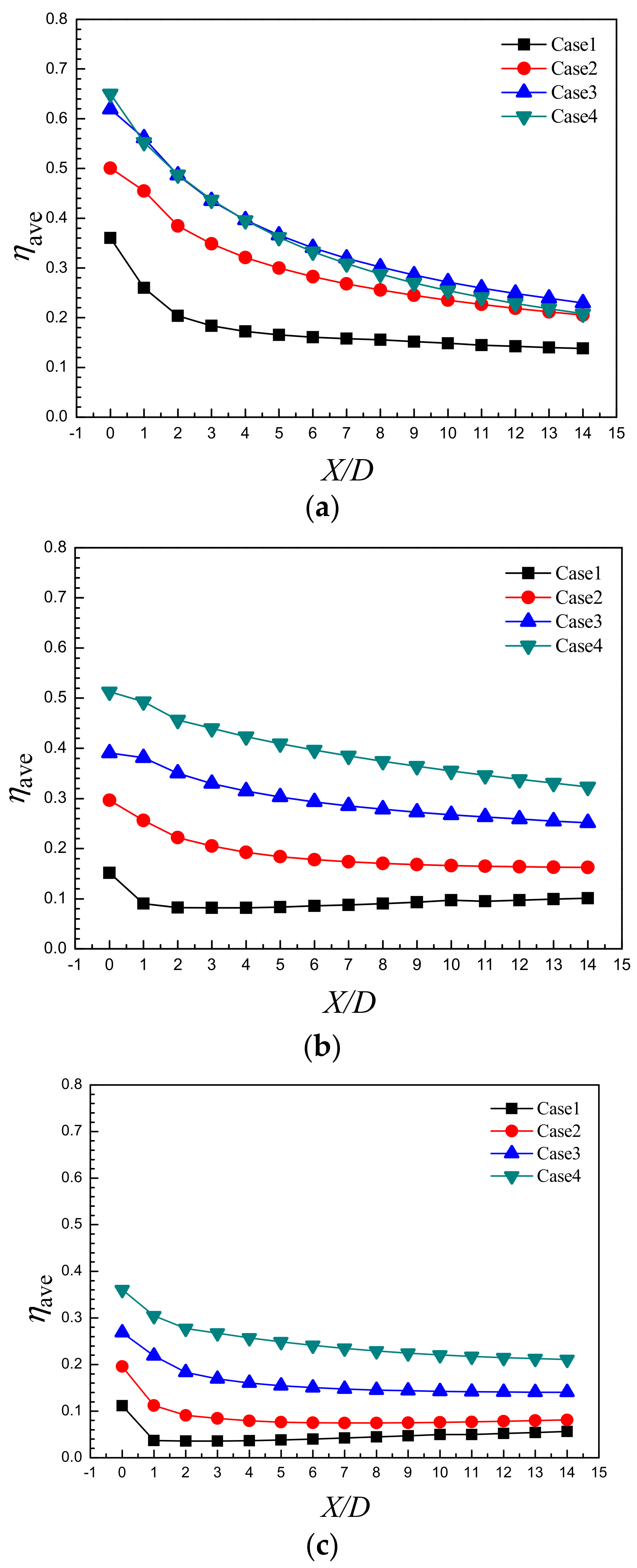
Figure 15 presents the laterally-averaged adiabatic film cooling effectiveness distributions along the streamwise direction. We confirmed that the upstream sand-dune-shaped ramp significantly improved the laterally-averaged film cooling effectiveness relative to the baseline cylindrical film cooling hole under all blowing ratios. With regards to the effects of ramp height, a relatively optimal ramp height seems to be 0.5D under a low blowing ratio, as seen in Figure 15a. Under a moderate or high blowing ratio, as seen in Figure 15b,c, the laterally-averaged adiabatic film cooling effectiveness improved gradually with the increase in ramp height.
4. Conclusions
This paper summarized a numerical study exploring the film cooling enhancement by the incorporation of an upstream sand-dune-shaped ramp (SDSR) into the film hole exit. The effect of ramp height was illustrated under three typical blowing ratios. We confirmed that the upstream sand-dune-shaped ramp significantly improved the laterally-averaged film cooling effectiveness compared to the baseline cylindrical film cooling hole under all blowing ratios.
The upstream SDSR effectively controlled the near-wall primary flow and subsequent mutual interaction with the coolant jet. First, the SDSR formed a pair of anti-kidney vortices at the trailing ridges of the SDSR, which helped suppress the kidney vortex pair due to the interaction between the coolant jet and the primary flow. Second, it induced a weak separation and a low pressure zone behind the backside of the SDSR, which helped entrain the coolant jet to spread around the film cooling hole.
The effect of the upstream SDSR was distinct under different blowing ratios. Under a low blowing ratio, the upstream SDSR shortened the streamwise film layer coverage in the vicinity of the film hole centerline but increased the span-wise film layer coverage. A relatively optimal ramp height seemed to be 0.5D. Under a high blowing ratio, both the streamwise and the spanwise film layer coverages all improved in comparison with the baseline case. The film cooling effectiveness was improved gradually with the increase in ramp height.
Author Contributions
S.-C.Z.: research design, data collection, data analysis and manuscript modification; J.-Z.Z.: research design, data analysis, literature search, manuscript writing and modification; X.-M.T.: research design, literature search and chart making.
Funding
This research was funded by [National Natural Science Foundation of China] grant number [U1508212]. And the APC was funded by [National Natural Science Foundation of China].
Acknowledgments
The authors gratefully acknowledge the spiritual support from our teammates.
Conflicts of Interest
The authors declare no conflicts of interest.
References
- Bunker, R.S. Gas Turbine Heat Transfer: Ten Remaining Hot Gas Path challenges. ASME J. Turbomach. 2007, 129, 193–210. [Google Scholar] [CrossRef]
- Bell, C.M.; Hamakawa, H.; Ligrani, P.M. Film Cooling from Shaped Holes. ASME J. Heat Transf. 2000, 122, 224–232. [Google Scholar] [CrossRef]
- Bunker, R.S. A review of Turbine Shaped Film Cooling Technology. ASME J. Heat Transf. 2005, 127, 441–453. [Google Scholar] [CrossRef]
- Na, S.; Shih, T.I.-P. Increasing Adiabatic Film-Cooling Effectiveness by Using an Upstream Ramp. ASME J. Heat Transf. 2007, 129, 464–471. [Google Scholar] [CrossRef]
- Barigozzi, G.; Franchini, G.; Perdichizzi, A. The Effect of an Upstream Ramp on Cylindrical and Fan-Shaped Hole Film Cooling: Part I—Aerodynamic Results. In Proceedings of the ASME Turbo Expo 2007: Power for Land, Sea, and Air, Montreal, QC, Canada, 14–17 May 2007. ASME Paper GT2007-27077. [Google Scholar]
- Barigozzi, G.; Franchini, G.; Perdichizzi, A. The Effect of an Upstream Ramp on Cylindrical and Fan-Shaped Hole Film Cooling: Part II—Adiabatic Effectiveness Results. In Proceedings of the ASME Turbo Expo 2007: Power for Land, Sea, and Air, Montreal, QC, Canada, 14–17 May 2007. ASME Paper GT2007-27079. [Google Scholar]
- Chen, S.P.; Chyu, M.K.; Shih, T.I.-P. Effects of Upstream Ramp on the Performance of Film Cooling. Int. J. Therm. Sci. 2011, 50, 1085–1094. [Google Scholar] [CrossRef]
- Rallabandi, A.P.; Grizzle, J.; Han, J.C. Effect of Upstream Step on Flat Plate Film Cooling Effectiveness Using PSP. ASME J. Turbomach. 2011, 133, 041024. [Google Scholar] [CrossRef]
- Yan, W.S.; Pu, J.; Wang, J.H. The Combined Effects of an Upstream Ramp and Swirling Coolant Flow on Film Cooling Characteristics. ASME J. Turbomach. 2016, 138, 111008. [Google Scholar]
- Abdala, A.M.; Elwekeel, F.N. An Influence of Novel Upstream Steps on Film Cooling Performance. Int. J. Heat Mass Transf. 2016, 93, 86–96. [Google Scholar] [CrossRef]
- Abdala, A.M.; Elwekeel, F.N.; Huang, D.G. Film Cooling Effectiveness and Flow Structures for Novel Upstream Step. Appl. Therm. Eng. 2016, 105, 397–410. [Google Scholar] [CrossRef]
- Zhou, W.; Hu, H. Improvements of Film Cooling Effectiveness by Using Barchan Dune Shaped Ramps. Int. J. Heat Mass Transf. 2016, 103, 443–456. [Google Scholar] [CrossRef]
- Zhou, W.; Hu, H. A Novel Sand-Dune-Inspired Design for Improved Film Cooling Performance. Int. J. Heat Mass Transf. 2017, 110, 908–920. [Google Scholar] [CrossRef]
- Keller, M.A.; Kloker, M.J. Direct Numerical Simulation of Foreign-Gas Film Cooling in Supersonic Boundary-Layer Flow. AIAA J. 2016, 55, 1–13. [Google Scholar] [CrossRef]
- Keller, M.A.; Kloker, M.J. Effusion Cooling and Flow Tripping in Laminar Supersonic Boundary-Layer Flow. Res. Vet. Sci. 2015, 59, 10–16. [Google Scholar] [CrossRef]
- Harrison, K.; Bogard, D. Comparison of RANS Turbulence Models for Prediction of Film Cooling Performance. In Proceedings of the ASME Turbo Expo 2008: Power for Land, Sea, and Air, Berlin, Germany, 9–13 June 2008. ASME Paper GT2008-50366. [Google Scholar]
- Silieti, M.; Kassab, A.J.; Divo, E. Film Cooling Effectiveness: Comparison of Adiabatic and Conjugate Heat Transfer CFD Models. Int. J. Therm. Sci. 2009, 48, 2237–2248. [Google Scholar] [CrossRef]
- Fly, M.J.; Jubran, B.J. A Numerical Evaluation on the Effect of Sister Holes on Film Cooling Effectiveness and the Surrounding Flow Filed. Heat Mass Transf. 2009, 45, 1435–1446. [Google Scholar]
- Nikparto, A.; Schobeiri, M.T. Combined numerical and experimental investigations of heat transfer of a highly loaded low-pressure turbine blade under periodic inlet flow condition. Proc. Inst. Mech. Eng. Part A J. Power Energy 2018. [Google Scholar] [CrossRef]
- Nikparto, A.A.; Rice, T.T.; Schobeiri, M.T. Experimental and Numerical Investigation of Heat Transfer and Film Cooling Effectiveness of a Highly Loaded Turbine Blade Under Steady and Unsteady Wake Flow Condition. In Proceedings of the Turbo Expo: Power for Land, Sea, and Air, Charlotte, NC, USA, 26–30 June 2017; ASME: New York, NY, USA, 2017. [Google Scholar]
Figure 1.
Schematic of computational domain.
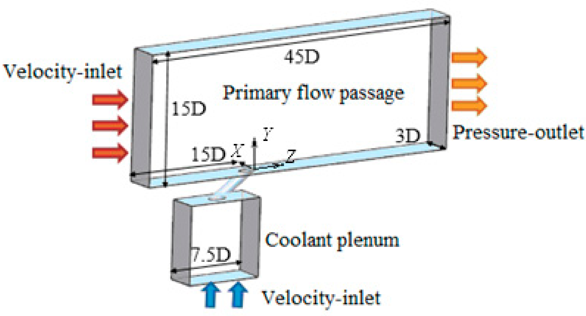
Figure 2.
Schematic of sand-dune-shaped ramp (SDSR) configuration: (a) three-dimensional (3D) view; (b) detailed parameters.
Figure 2.
Schematic of sand-dune-shaped ramp (SDSR) configuration: (a) three-dimensional (3D) view; (b) detailed parameters.

Figure 3.
The boundary layer velocity profile of numerical simulation at upstream of the hole exit.

Figure 4.
The validation of computational scheme by comparing with the experimental data reported by Zhou et al. [12]: (a) Centerline film cooling effectiveness, and (b) laterally-averaged effectiveness.
Figure 4.
The validation of computational scheme by comparing with the experimental data reported by Zhou et al. [12]: (a) Centerline film cooling effectiveness, and (b) laterally-averaged effectiveness.

Figure 5.
Computational grids and sensitivity test. (a) Local grids; (b) Centerline adiabatic film cooling effectiveness.
Figure 5.
Computational grids and sensitivity test. (a) Local grids; (b) Centerline adiabatic film cooling effectiveness.
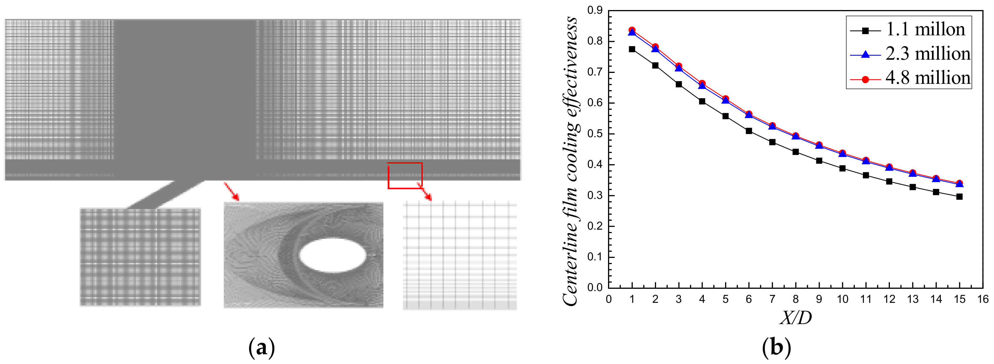
Figure 6.
The distributions of vorticity contours and streamlines at X/D = 2 under M = 1.0 and (a) Case 1, Cylindrical hole; (b) Case 2, SDSR-Hd = 0.25D; (c) Case 3, SDSR-Hd = 0.5D; and (d) Case 4, SDSR-Hd = 0.75D.
Figure 6.
The distributions of vorticity contours and streamlines at X/D = 2 under M = 1.0 and (a) Case 1, Cylindrical hole; (b) Case 2, SDSR-Hd = 0.25D; (c) Case 3, SDSR-Hd = 0.5D; and (d) Case 4, SDSR-Hd = 0.75D.

Figure 7.
Dimensionless temperature contours and streamlines on film hole centerline plane under M = 1.0 for (a) Case 1, cylindrical hole; and (b) Case 3, SDSR-Hd = 0.5D.
Figure 7.
Dimensionless temperature contours and streamlines on film hole centerline plane under M = 1.0 for (a) Case 1, cylindrical hole; and (b) Case 3, SDSR-Hd = 0.5D.
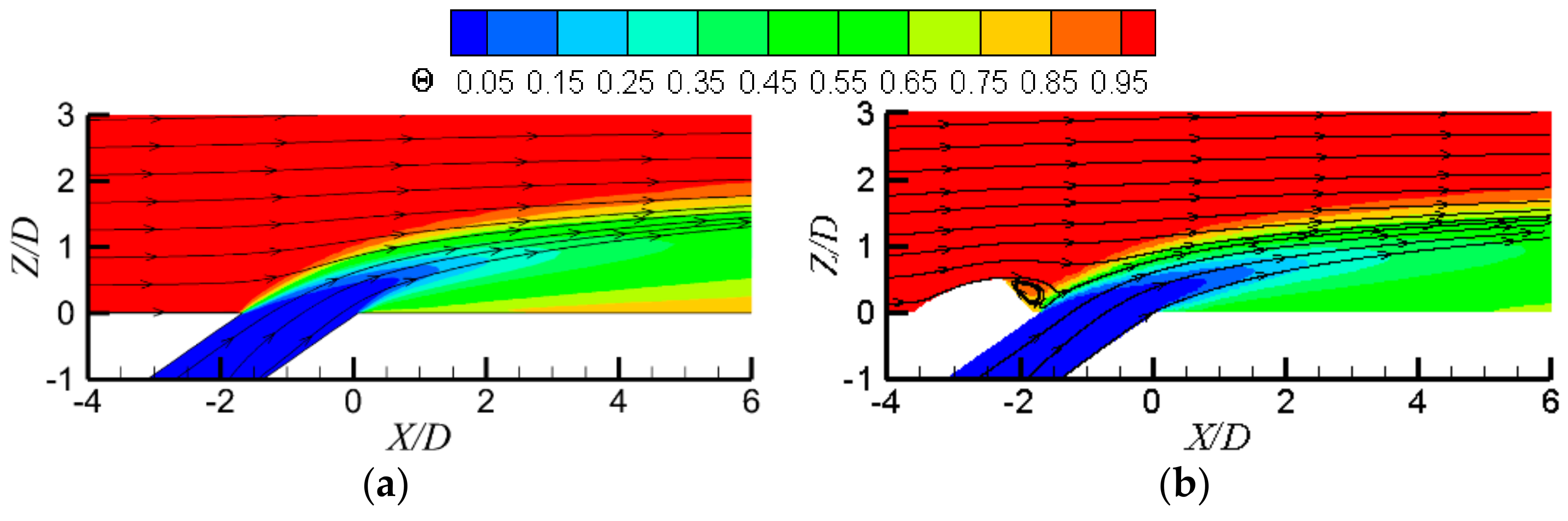
Figure 8.
Detailed flow features for Case 4 at M = 1.0. (a) Z/D = 0.125; (b) Y/D = 0; and (c) local streamlines.
Figure 8.
Detailed flow features for Case 4 at M = 1.0. (a) Z/D = 0.125; (b) Y/D = 0; and (c) local streamlines.
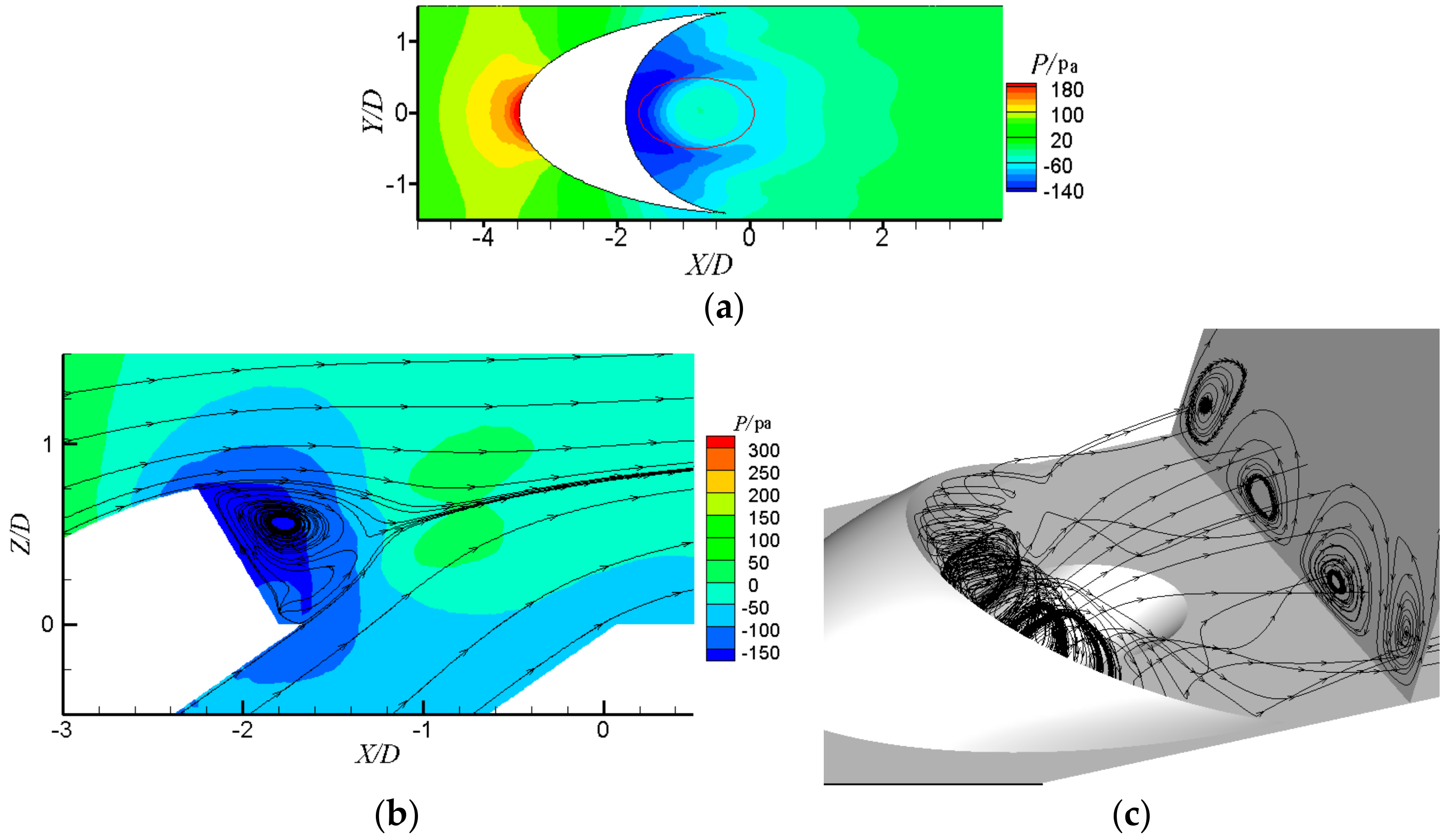
Figure 9.
The relative static pressure distributions on hole entrance and hole exit under the blowing ratio of 1.0 and left side: hole entrance, right side: hole exit. (a) Case 1, Cylindrical hole, hole entrance; (b) Case 1, Cylindrical hole, hole exit; (c) Case 3, SDSR-Hd = 0.5D, hole entrance; (d) Case 3, SDSR-Hd = 0.5D, hole exit; (e) Case 4, SDSR-Hd = 0.75D, hole entrance; (f) Case 4, SDSR-Hd = 0.75D, hole exit.
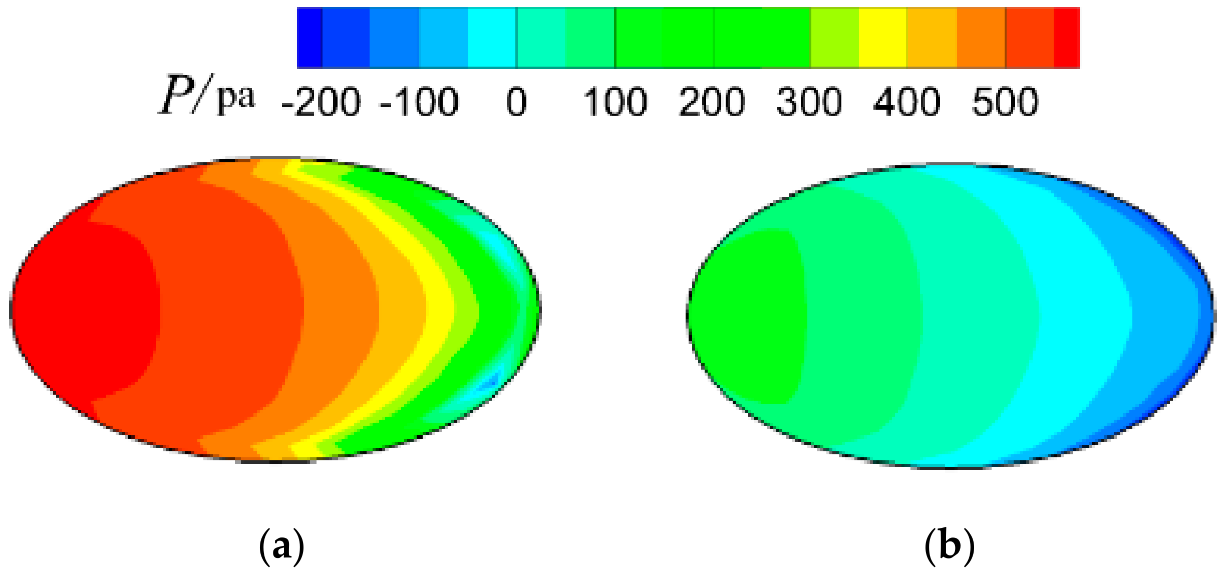

Figure 10.
The relative total pressure contours on the hole exit under a blowing ratio of 1.0: (a) Case 1, cylindrical hole; (b) Case 3, SDSR-Hd = 0.5D; and (c) Case 4, SDSR-Hd = 0.75D.
Figure 10.
The relative total pressure contours on the hole exit under a blowing ratio of 1.0: (a) Case 1, cylindrical hole; (b) Case 3, SDSR-Hd = 0.5D; and (c) Case 4, SDSR-Hd = 0.75D.

Figure 11.
The nondimensional turbulent kinetic energy contours on film hole centerline plane under M = 1.0: (a) Case 1, cylindrical hole; (b) Case 2, SDSR-Hd = 0.25D; (c) Case 3, SDSR-Hd = 0.5D; and (d) Case 4, SDSR-Hd = 0.75D.
Figure 11.
The nondimensional turbulent kinetic energy contours on film hole centerline plane under M = 1.0: (a) Case 1, cylindrical hole; (b) Case 2, SDSR-Hd = 0.25D; (c) Case 3, SDSR-Hd = 0.5D; and (d) Case 4, SDSR-Hd = 0.75D.

Figure 12.
Local adiabatic film cooling effectiveness under M = 0.5 and (a) Case 1, cylindrical hole; (b) Case 2, SDSR-Hd = 0.25D; (c) Case 3, SDSR-Hd = 0.5D; and (d) Case 4, SDSR-Hd = 0.75D.
Figure 12.
Local adiabatic film cooling effectiveness under M = 0.5 and (a) Case 1, cylindrical hole; (b) Case 2, SDSR-Hd = 0.25D; (c) Case 3, SDSR-Hd = 0.5D; and (d) Case 4, SDSR-Hd = 0.75D.
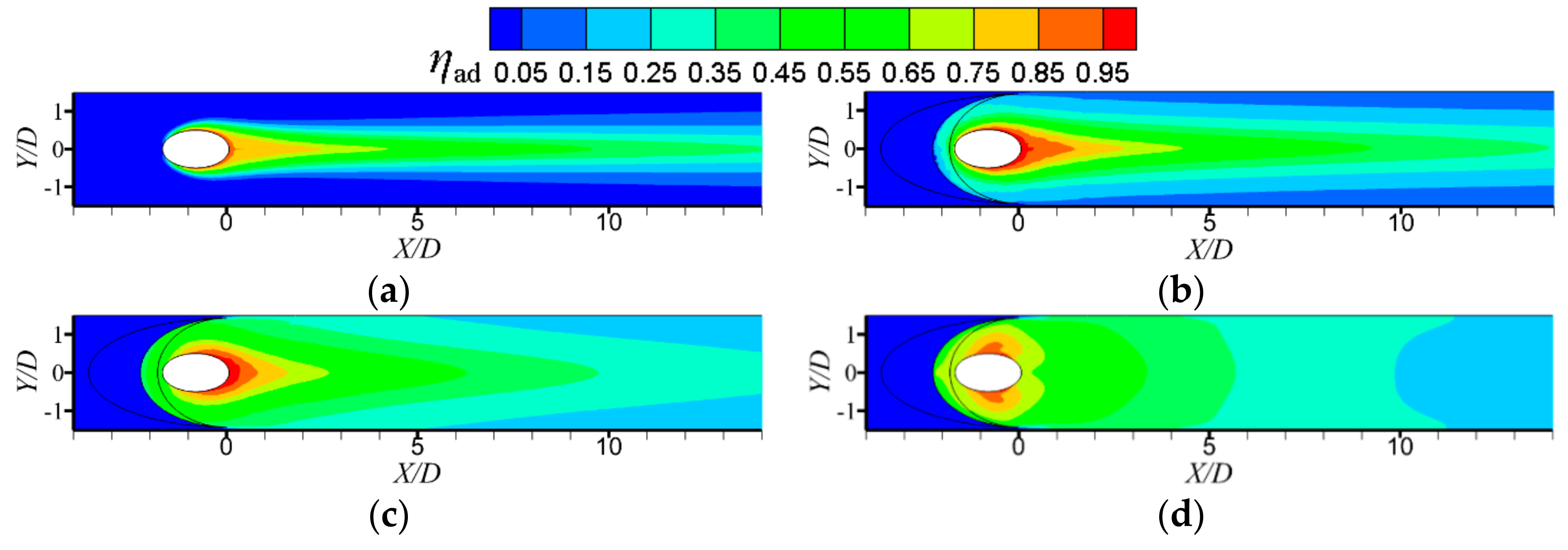
Figure 13.
Local adiabatic film cooling effectiveness under M = 1.0: (a) Case 1, cylindrical hole; (b) Case 2, SDSR-Hd = 0.25D; (c) Case 3, SDSR-Hd = 0.5D; and (d) Case 4, SDSR-Hd = 0.75D.
Figure 13.
Local adiabatic film cooling effectiveness under M = 1.0: (a) Case 1, cylindrical hole; (b) Case 2, SDSR-Hd = 0.25D; (c) Case 3, SDSR-Hd = 0.5D; and (d) Case 4, SDSR-Hd = 0.75D.
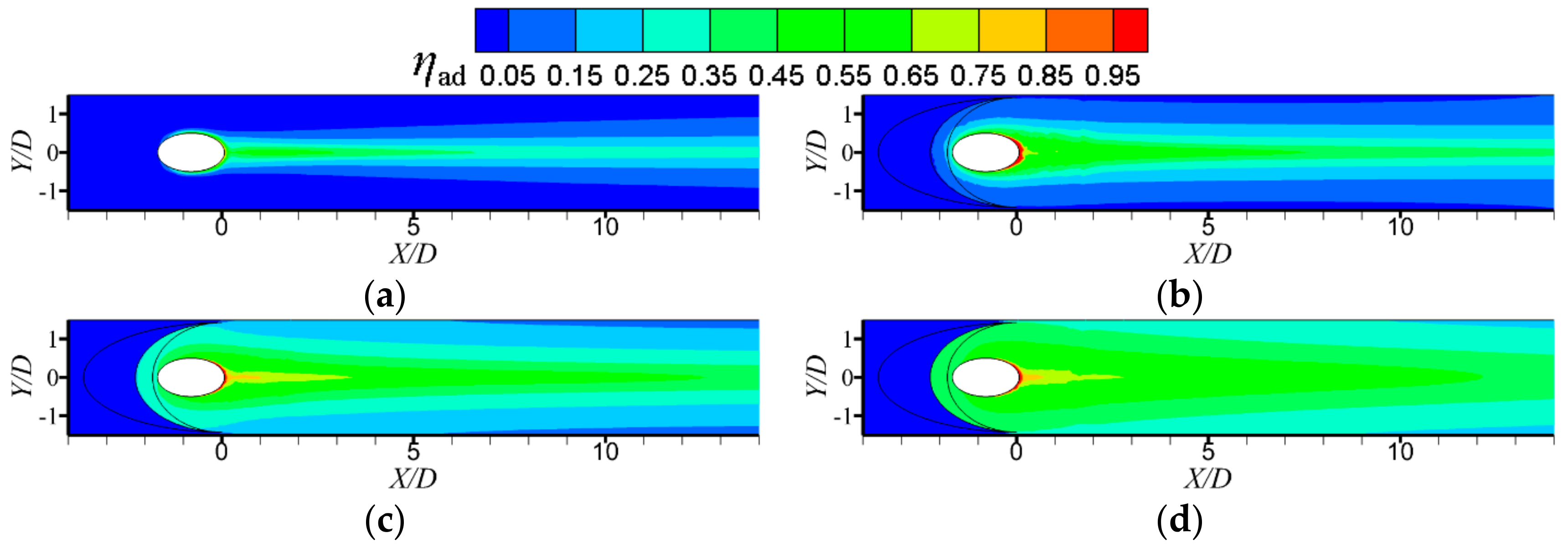
Figure 14.
Local adiabatic film cooling effectiveness under M = 1.5: (a) Case 1, cylindrical hole; (b) Case 2, SDSR-Hd = 0.25D; (c) Case 3, SDSR-Hd = 0.5D; and (d) Case 4, SDSR-Hd = 0.75D.
Figure 14.
Local adiabatic film cooling effectiveness under M = 1.5: (a) Case 1, cylindrical hole; (b) Case 2, SDSR-Hd = 0.25D; (c) Case 3, SDSR-Hd = 0.5D; and (d) Case 4, SDSR-Hd = 0.75D.

Figure 15.
Laterally-averaged adiabatic film cooling effectiveness along streamwise direction: (a) M = 0.5; (b) M = 1.0; and (c) M = 1.5.
Figure 15.
Laterally-averaged adiabatic film cooling effectiveness along streamwise direction: (a) M = 0.5; (b) M = 1.0; and (c) M = 1.5.


Table 1.
Geometric parameters of sand-dune-shaped ramp.
| Parameter | Value (mm) | Parameter | Value (mm) |
|---|---|---|---|
| L0 | 3.2 | Lf | 5.4 |
| L1 | 4.0 | Lm | 1.8 |
| Lb | 7.2 | W | 11.4 |
© 2018 by the authors. Licensee MDPI, Basel, Switzerland. This article is an open access article distributed under the terms and conditions of the Creative Commons Attribution (CC BY) license (http://creativecommons.org/licenses/by/4.0/).
Share and Cite
MDPI and ACS Style
Zhang, S.-C.; Zhang, J.-Z.; Tan, X.-M. Numerical Investigation of Film Cooling Enhancement Using an Upstream Sand-Dune-Shaped Ramp. Computation 2018, 6, 49. https://doi.org/10.3390/computation6030049
AMA Style
Zhang S-C, Zhang J-Z, Tan X-M. Numerical Investigation of Film Cooling Enhancement Using an Upstream Sand-Dune-Shaped Ramp. Computation. 2018; 6(3):49. https://doi.org/10.3390/computation6030049
Chicago/Turabian StyleZhang, Sheng-Chang, Jing-Zhou Zhang, and Xiao-Ming Tan. 2018. "Numerical Investigation of Film Cooling Enhancement Using an Upstream Sand-Dune-Shaped Ramp" Computation 6, no. 3: 49. https://doi.org/10.3390/computation6030049
Note that from the first issue of 2016, this journal uses article numbers instead of page numbers. See further details here.