
Design of a Binocular Pupil and Gaze Point Detection System Utilizing High Definition Images


Department of Electrical and Electronics Engineering, Ankara University, Ankara 06830, Turkey
*
Author to whom correspondence should be addressed.
Appl. Sci. 2017, 7(5), 498; https://doi.org/10.3390/app7050498
Submission received: 1 March 2017
/
Revised: 4 May 2017
/
Accepted: 8 May 2017
/
Published: 11 May 2017
Abstract
:This study proposes a novel binocular pupil and gaze detection system utilizing a remote full high definition (full HD) camera and employing LabVIEW. LabVIEW is inherently parallel and has fewer time-consuming algorithms. Many eye tracker applications are monocular and use low resolution cameras due to real-time image processing difficulties. We utilized the computer’s direct access memory channel for rapid data transmission and processed full HD images with LabVIEW. Full HD images make easier determinations of center coordinates/sizes of pupil and corneal reflection. We modified the camera so that the camera sensor passed only infrared (IR) images. Glints were taken as reference points for region of interest (ROI) area selection of the eye region in the face image. A morphologic filter was applied for erosion of noise, and a weighted average technique was used for center detection. To test system accuracy with 11 participants, we produced a visual stimulus set up to analyze each eye’s movement. Nonlinear mapping function was utilized for gaze estimation. Pupil size, pupil position, glint position and gaze point coordinates were obtained with free natural head movements in our system. This system also works at 2046 × 1086 resolution at 40 frames per second. It is assumed that 280 frames per second for 640 × 480 pixel images is the case. Experimental results show that the average gaze detection error for 11 participants was 0.76° for the left eye, 0.89° for right eye and 0.83° for the mean of two eyes.
1. Introduction
Nowadays, human senses and anatomical features are used in various applications. In particular, information collected from movement of hands, head and eyes are utilized as an input argument for different systems such as intelligent systems, robot control, security, assistive applications, and human diagnosis, etc. As a matter of fact, these inputs are essential for increasing the reliability of above-mentioned systems. Among these movements, eye movement is the most popular because of its crucial role in transmitting huge environmental data to the brain.
Human beings acquire 80–90% of the external world knowledge from their eyes [1]. The human eye has communication with the brain at very high speed and wide band [2]. Accordingly, vision is the most important part of our senses. Currently, it is likely that our behaviors and considerations might be recognizable with the help of the eye gaze. Where we place and how we move our gaze is associated with what we pay attention to [3]. In this regard, the significance of visual information and information evaluators is growing.
Visual information can be acquired through eye gaze tracking. Gaze tracking technology includes a sophisticated device that tracks and records where people look, together with movements of the eye gaze. In the literature, the most popular eye tracking methods are electrooculogram (EOG) [4], scleral magnetic search coils [5] and noninvasive video-based pupil-corneal reflection tracking [6].
A contemporary and widely-adopted method among traditional gaze tracking methods [7,8,9] is video image based pupil center-corneal reflection method (PCCR) which does not require physical contact with the user’s eye area. As it is not intrusive, PCCR is considered to be the most improved gaze tracking technology in recent years [10,11]. In PCCR methods, pupil center relative position with respect to corneal reflection which is called “glint” is the main point. Besides this, gaze estimation is performed by detecting the center of the pupil and corneal reflections created by illuminators. Consequently, gaze estimations are done via using single [12,13] or multiple illuminator-based methods [14,15,16] in many eye tracking studies.
Eye gaze tracking systems can employ visible or infrared (IR) light as an illuminator. When visible light is preferred, it is difficult to detect pupil center and distinguish the pupil from noisy reflections. On the other hand, IR light eases pupil detection by means of near infrared (NIR) cameras. Thus, many eye tracker applications use IR light with NIR cameras. According to the eye tracking processes, one or more NIR cameras are utilized to obtain 2D or 3D video images. Three-dimensional video image-based systems have higher accuracies but they have lower working frequencies.
Eye gaze estimation of users can be carried out using lots of techniques. Eye trackers have been designed as wearable or as remote gaze tracking systems. In the form of a wearable system, an eye tracking camera is mounted on the user’s head [17,18]. In the remote system, visual perception is acquired by a remote camera system [19,20]. This case is more convenient for the users.
Recently, several video-based pupil detection algorithms such as the Ellipse selector (ElSe) [21], the Exclusive Curve Selector (ExCuSe) [22], and the Convolutional Neural Network (CNN) [23] have been proposed to estimate eye pupil at high detection rates and low computational costs. The Ellipse selector (ElSe) is based on ellipse evaluation of a filtered edge image and pupil contour validation. It is a robust, resource-saving approach that can be integrated in embedded architectures. ExCuSe analyses the images depending on reflections based on intensity histograms. Edge detectors, morphologic operations, and the angular integral projection function are applied to detect the pupil contour in this algorithm. CNN is a dual convolutional neural network pipeline. In the first stage, the pipeline performs pupil position determination using a convolutional neural network. Then, subregions are derived from the downscaled input image. The second pipeline stage employs another convolutional neural network to refine this pupil position by means of the subregions. These algorithms have contributed to create eye image-based data sets. These data sets include real world scenarios, such as illumination changes, reflections (on glasses), make-up, non-centered eye recording, and physiological eye characteristics. ExCuSe used Swirski data set and provided 17 new hand-labeled data sets. ElSe used Swirski and ExCuse data sets and provided seven new hand-labeled data sets. These studies were performed on approximately 200,000 frames [24].
It is proven that eye gaze systems’ accuracies increase when the users’ head movements are restricted. To achieve high level accuracy values, many commercial companies use a chin rest to keep the head fixed while the gaze estimation process is performed with a desktop-mounted gaze tracking system. At the beginning of the gaze estimation, users are taken into the calibration process. Generally, users are asked to look at one, four or nine points located on the screen [25,26]. If the number of the calibration points is augmented, gaze estimation error decreases. Gaze estimation error is still a challenge in which linear or nonlinear functions are applied to overcome.
Gaze tracking systems have been extensively exploited in different application areas such as human computer interaction, aviation, medicine, robot control, production tests, augmented reality, psychoanalysis, sports training, computer games, training simulators, laser surgery, flight simulations, product development, fatigue detection, and in the military.
Another application area of eye gaze tracking system is pupillometry. Pupillometry is the measurement of eye pupil size. Normally, human pupil size range is 2–8 mm [27]. Additionally, ambient light and environmental factors may affect pupil size changes. Besides that, pupillometry shows tonic and phasic changes in pupil size that play a significant role in observing normal and abnormal functioning of the nervous system [28]. Recent research has revealed that pupil abnormalities are correlated with many diseases such as multiple sclerosis, migraines, diabetes, alcoholism, depression, anxiety/panic disorder, Alzheimer´s disease, Parkinson´s disease, and autism [29].
Different disciplines may take advantage of differences in pupil size and eye movements. Also, eye movement analysis with fast systems are providing new opportunities in psychology, neuroscience, ophthalmology and affective computing.
Affective computing has multidisciplinary applications. Automatic detection of human emotional states increases the computer’s understanding of the human needs. Eye movements hold essential power for recognizing positive and negative emotions. Affective computing contributes to many areas. Some of these can be listed as follows. The cognitive load of a student can be found using eye tracking. Understanding the affective state of a student allows effective and improved learning. Someone’s mood can also be inferred from the eyes. This is currently used to monitor the emotional state of patients. Personalization of commercial products can be enhanced by recognizing the human’s mood. Affective computing enhances applications such as virtual reality and smart surveillance. Another point is the automatic recognition of emotions that could also be useful to support psychological studies. Such studies give a baseline for the emotional reaction of healthy subjects, which could be compared and used to diagnose mental disorders [30]. Now it is possible that cars recommend music depending on the human’s mood and pull to the side of the road when they sense driver’s fatigue.
Recently, eye tracking technologies have revealed options useful for pupillometry. To have correct results in pupillometry, a high frequency and high resolution image-based eye tracking system is required. Nowadays, commercially available eye gaze tracking devices have monocular or binocular head movement-free applications and achieve up to 1000 fps (frames per second) frequencies [31,32]. Low resolution (up to 640 × 480) and low frequency (up to 30 Hz) cameras are selected to decrease the cost of design.
Su et al. [33] proposed a monocular eye gaze tracking system which works at 15.7 Hz with 1600 × 1200 pixel images for users wearing glasses. Their study is based on the detection of user’s glasses and minimizing reflections on the surface of the glasses to facilitate pupil region detection by utilizing an illuminator controller device. Ji et al. [11] presented a monocular head mounted eye gaze tracking system which works at 27 Hz with 640 × 480 pixel images. Their method is aimed at reducing points seen by the user. This is inconvenient for the user during calibration stage as it generates virtual calibration points. Also, Jong et al. [34] proposed a new method for gaze estimation. They diminished the additional corneal reflections caused by external light using band pass filter located on front of the camera. Their system is a binocular remote eye tracker that operates at 20 Hz with 1600 × 1200 pixel images.
In this study, we presented a remote eye gaze tracking and record system that has the ability to process full high definition (full HD) images. The system frequency is 40 Hz for full HD images. This corresponds to 280 Hz for 640 × 480 size images. Outputs of our system are pupil sizes, pupil center positions, glint center positions and estimated gaze points. With these outputs, it is possible to interpret eye gaze and pupil information. The accuracy of our system is to less than one degree, which is a good level for single camera-based binocular systems. We developed this system by employing the LabVIEW program which is inherently parallel and has less time-consuming image processing algorithms. The remainder of this paper is organized as follows: Section 2 describes the details of the proposed method. Section 3 explains the experimental setup and results. Finally, the conclusions are presented in Section 4.
2. Proposed Binocular Eye Gaze Tracking System
2.1. Proposed Gaze Tracking System
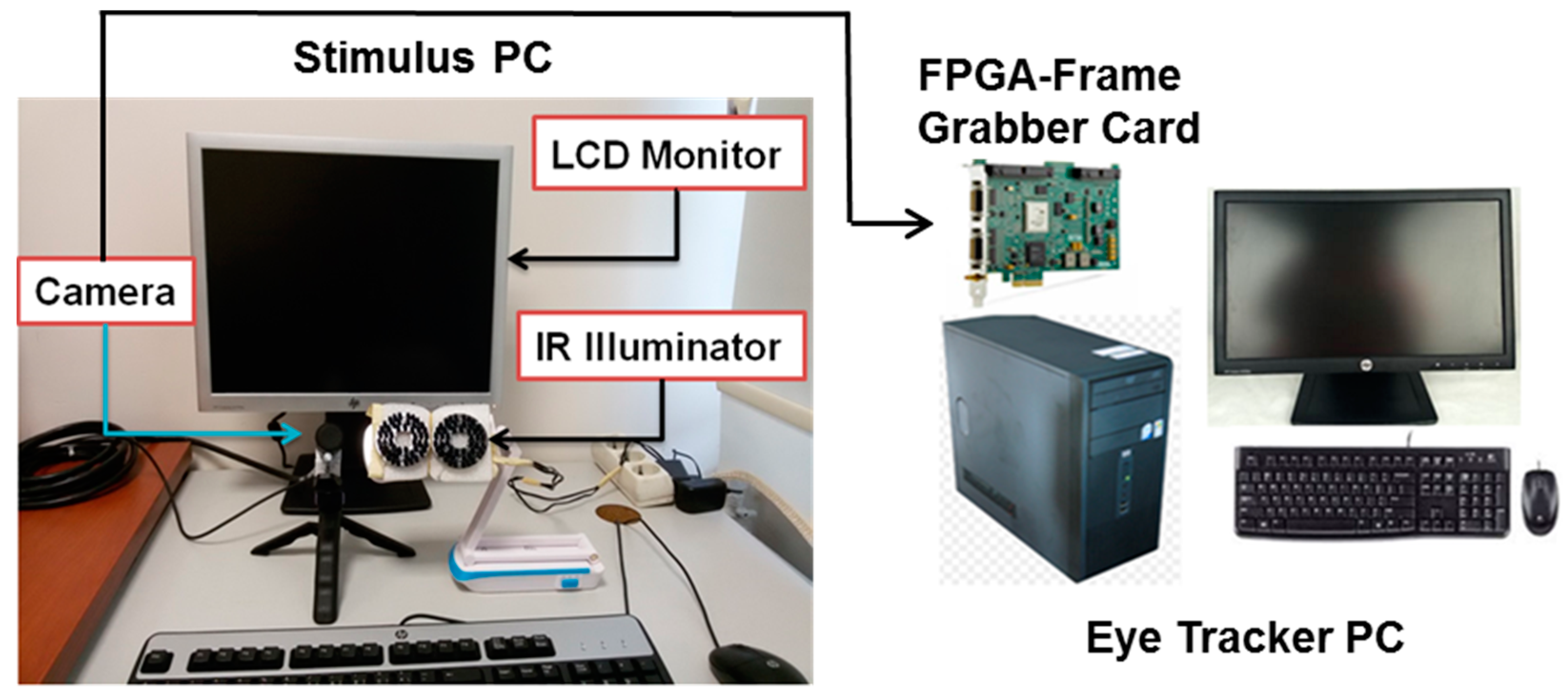
In our study, we designed an eye tracker system which consists of a camera link interface eye capture camera [35], FPGA-frame grabber card [36], an IR illuminator group and eye tracker/stimulus PCs as shown in Figure 1.
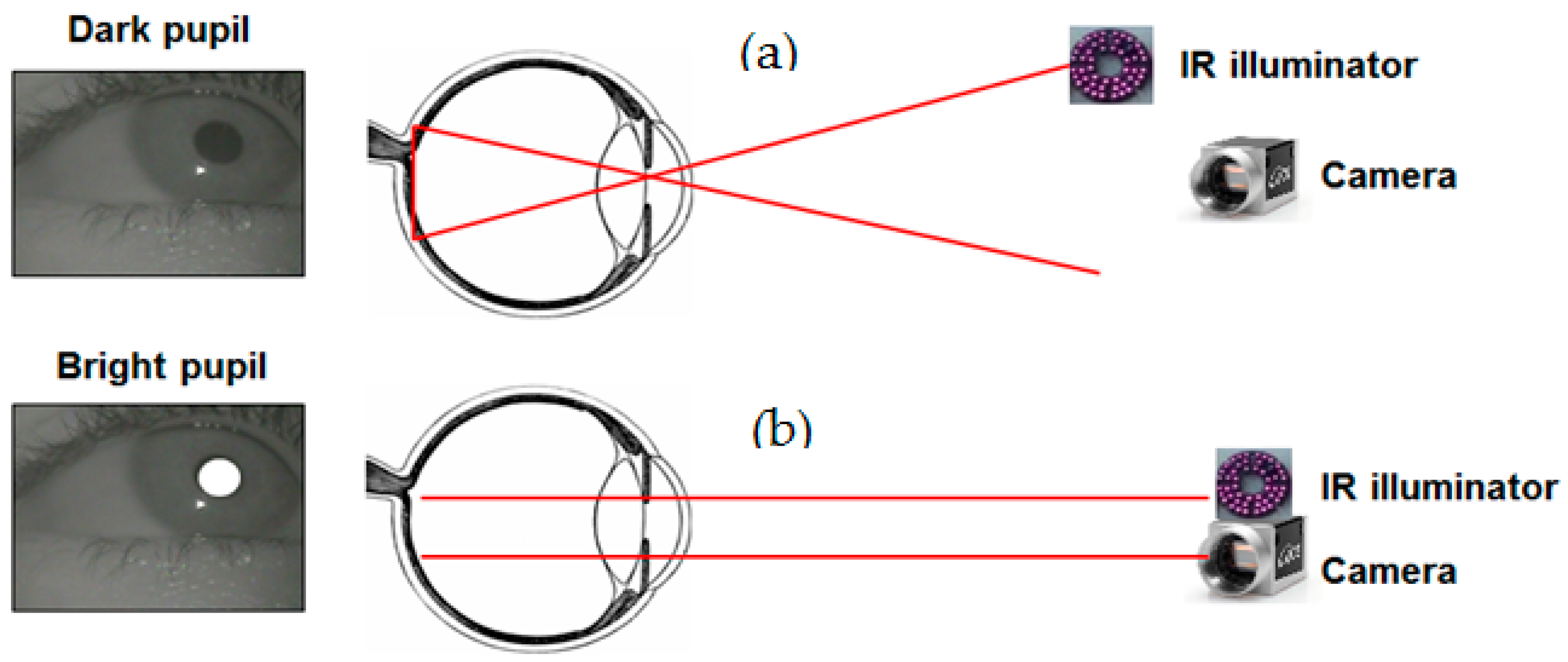
The camera is colorful and operates up to 340 fps with camera link interface. We adopted the camera with a lens which has a focal length of 16 mm, and vertical 23.7°–horizontal 30.7° field of view angles. IR illuminators are located around the eye capture NIR camera to ease the detection of pupil area in two ways. The first way is through dark pupil eye tracking, where an illuminator is placed away from the camera’s optical axis causing the pupil to appear darker than the iris as seen in Figure 2a. The second way is through bright pupil eye tracking, where an illuminator is placed close to the optical axis of the camera causing the pupil to appear brighter than the iris as shown in Figure 2b.
During remote eye tracking different factors can affect the pupil detection. Bright pupil eye tracking can be effected by environment illumination more than dark pupil tracking. Age and environmental illumination changes the size of the pupil in this method. Ethnicity is also another factor. Bright pupil eye tracking works very well for Hispanics and Caucasians but worse for Asians.
We preferred first way of IR illuminator location and our design is based on dark pupil eye tracking. To obtain IR images from a colorful camera, there is something which is performed on the camera to change the spectral response. The spectral response gives information about the characteristics of lens, light source, and IR cut filter. Our camera has an IR cut filter that passes only visible light wavelengths. The filter transmits in a range from 400 nm to 720 nm, and it cuts off from 720 nm to 1100 nm [35].
IR illumination effect can be obtained by modifying the camera filter. We removed the IR cut filter and placed a positive film in front of the camera sensor as shown in Figure 3. The camera spectral response is changed after the modification. The modified spectral response prevents undesired corneal reflections in our design.
Before and after the modification of the camera, we measured the spectral responses of the camera utilizing Shimadzu UV-3600 UV-VIS-NIR spectrophotometer (Shimadzu Corporation, Kyoto, Japan) and results are depicted in Figure 4.
Our design contains two IR illuminators. Each illuminator includes 48 near infrared light emitting diodes (NIR LEDs) with wavelengths of 850 nm. The radiant intensity of each NIR LED is 40 mW/sr and the illuminators are harmless to human eyes [37]. These two illuminators generate one corneal reflection.
2.2. Proposed Gaze Tracking Method
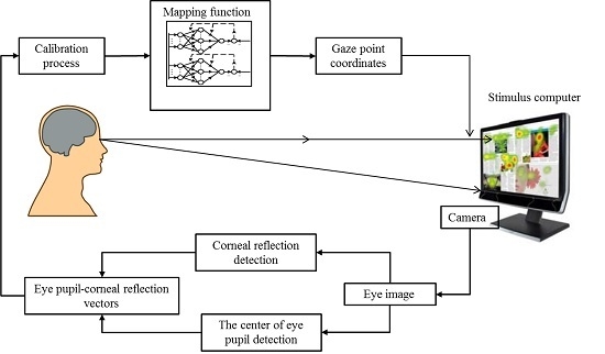
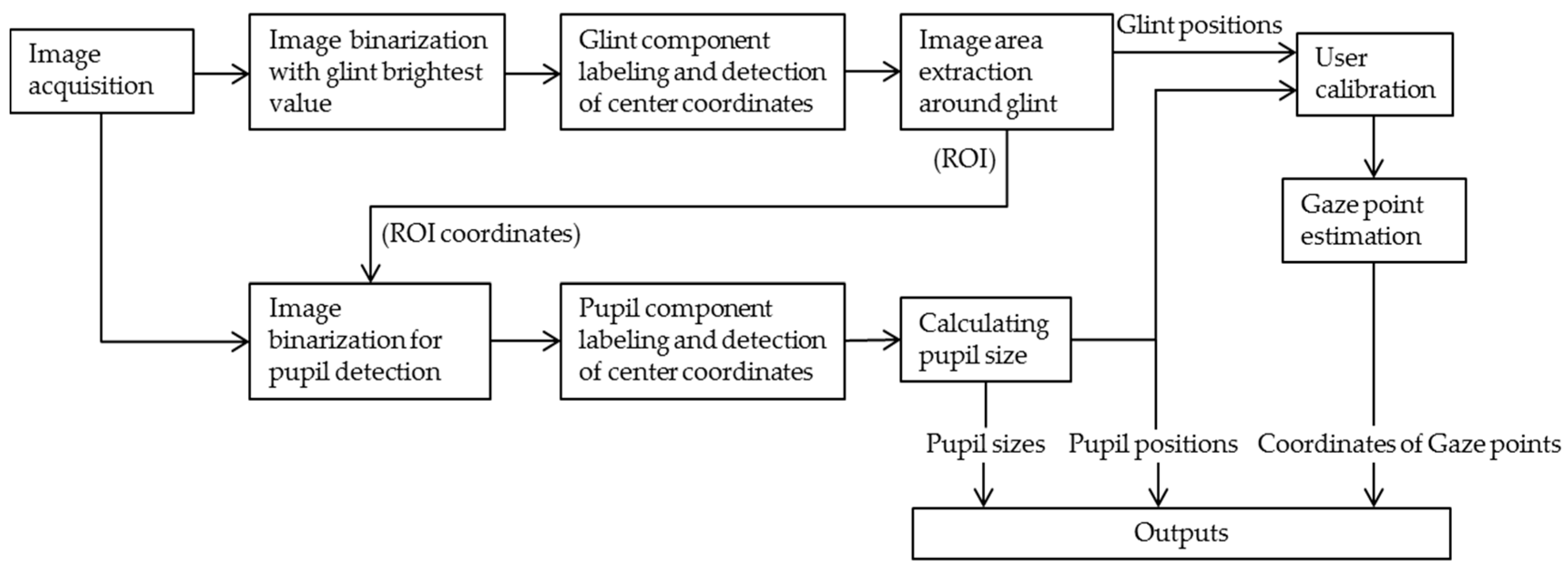
Figure 5 shows a flow chart of the eye gaze tracking system developed in this study. It includes preprocessing of raw gray images, region of interest (ROI) area determination around glint centers, center detection of pupils, nonlinear mapping function for gaze estimation and size calculation of pupils.
2.3. Detection of Pupil and Corneal Reflection
In this design, we grab images with NI PCIe-1473R FPGA frame grabber card located in the PCIe slot of the eye tracker desktop computer. Our software (its interface is shown in Figure 6) reads image frames from the computer’s direct memory access (DMA) channels which transfer data from and to the frame grabber. With the DMA, the CPU first initiates the transfer, and then performs other operations while the transfer is in progress. It receives an interruption by the DMA controller when the operation is accomplished. DMA usage provides great convenience such that the CPU does not need to trace data transfer while performing other works.
In the beginning of the transferred image frame processing, we created a temporary memory location in the LabVIEW for the image and to save flowing gray level images for processing. After one image frame processing is complete, the memory is evacuated for the next frame.
In our design, we considered corneal reflections (first Purkinje reflection) as a reference point for pupil searching. IR passing filter fulfills this step for us. Corneal reflection is called ‘glint’ [25]. It has the brightest value in the grabbed image, so it is easy to detect. Thus, a captured 10-bit resolution (1–1024) gray level image is firstly transformed into a binary image using Equation (1).
where, f(x, y) corresponds the pixel value at x-y axis coordinate in the gray level image while g (x, y) is the binary value at x-y axis coordinate of the image after thresholding process. Threshold level (T) can be determined by automatically or manually. However, automatic algorithms increase the process time of the image. Therefore, we assumed that the determination of the glint threshold can be made experimentally since glint has high luminance. We manually selected glint threshold value as 1020 after experimental trials. Then, component labeling was applied to the segmented parts from background image. Small-sized parts were removed from the image to clear rough right and left eye glints with erosion operation utilizing morphological filter. These filters give the capability to ignore the objects smaller or larger than given sizes. We removed objects smaller than 15 pixels using the filter.
To find the center coordinates of corneal reflections, we used a weighted average technique which is implemented faster than elliptic and circular shape center detection methods. The weighted average is found by multiplying the location of the pixel by its value and then dividing it by the number of pixels in the labelled corneal reflection mass as in Equation (2) where x and y are the position of the pixel and I(x, y) is the pixel value, respectively. In addition, w represents the width of the image and h represents the height of the image in pixels. The results are x’ and y’-central coordinates for each glint.
It is likely that pupils are close to glints. After detection of the glints’ centers, we defined a 100 × 100 pixel square ROI area. Its center coordinates are same as the coordinates of the glint centers. Then, we extracted ROI area in the raw gray level image and saved it in the memory. Glint detection image processing steps are also applied when detecting center coordinates of the pupil.
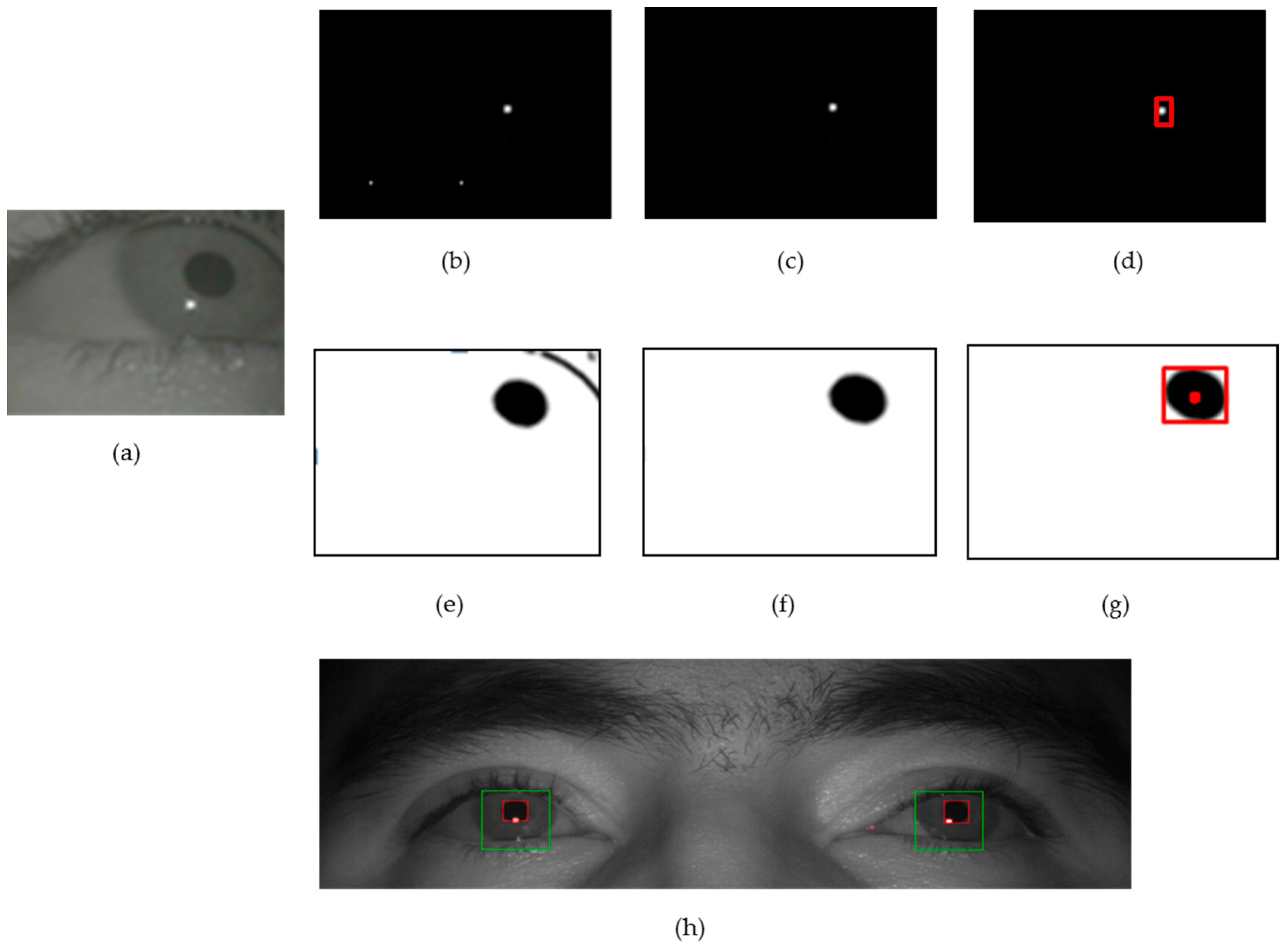
Because pupils have the darkest value and the largest object in the extracted image, it is easy to detect them. Thus, a captured 10-bit resolution (0–1024) gray level image is transformed into a binary image using Equation (1). Extracted ROI area image histogram values were measured for 11 users and we saw that small differences occurred. Accordingly, depending on the minimum and maximum histogram values, we manually adjusted the pupil threshold value (T) at 120 after experimental results. Then, component labeling is applied to the segmented objects from background image. Small size parts are removed from the image to clear rough right and left eye pupils with erosion operation utilizing a morphological filter. We removed the objects smaller than 250 pixels in size, which was determined experimentally. The object size value is obtained after the trials of the users’ small head movements which cause object size to change according to user to screen distance. Since human eye is not an exact circle, pupil size detection is not entirely possible with circular or elliptic methods. Hence, we used mass estimation of pupils. Thus, a weighted average technique (Equation (2)) was used to find the center coordinates of pupils. For the detection of glint mass and pupil mass center coordinates, we took advantage of LabVIEW Count Objects function. We presented our glint-pupil detection process in Figure 7.
2.4. Calibration and Gaze Point Estimation
Eye tracker systems use linear or nonlinear methods when transforming eye image coordinates to user screen coordinates. In this study, we applied second-order polynomial equation to estimate user screen gaze points. In general, second-order polynomials are chosen as the mapping function shown in Equation (3).
Estimation of pupil center x-y coordinates position (Sx, Sy) on the user screen is obtained by Equation (3) as follows:
Equation (4) is a transform matrix of Equation (3). This expression is represented with Equations (5) and (6).
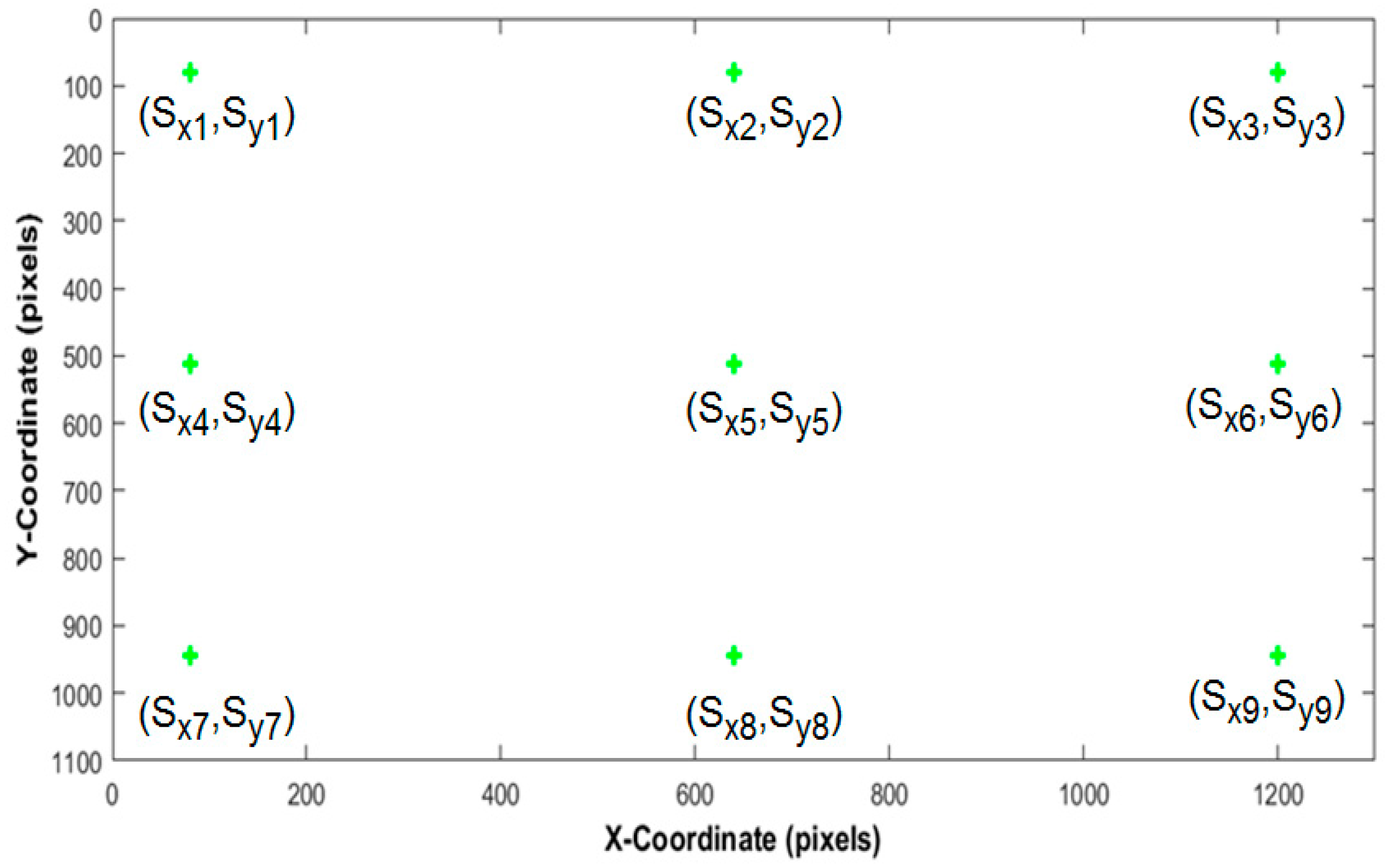
In Equations (5) and (6), ‘A’ matrix values are unknown constants, ‘B’ matrix values are coordinates of the calibration points on the user screen and ‘X’ matrix values are pupil center x-y coordinates in the captured images. ‘A’ matrix values are calculated during the calibration process. In our study, the calibration process is performed using nine points on the screen as shown in Figure 8.
x and y coordinates (pixels) of these nine calibration points from 1 to 9 are (80, 80), (640, 80), (1200, 80), (80, 512), (640, 512), (1200, 512), (80, 944), (640, 944) and (1200, 944), respectively. ‘X’ matrix values can be taken as a difference vector of glint (gx, gy) and pupil (px, py) center coordinates. Therefore, Equation (3) is reorganized as Equation (8) utilizing Equation (7).
After a calibration period, found constants (A) are used for mapping the pupil center coordinates in the test image to the user screen positions in pixels as follows:
2.5. Stimulus Application
Stimulus signals hold significant space in eye tracker applications. System performance is tested and the behaviors of the user’s eyes can be observed at quantitative values. The measured reactions solve many medical, mental, psychological, educational problems of human beings. Accordingly, we created a visual stimulus set up in Matlab, using the Psychophysics Toolbox extensions [38,39,40] as in Figure 9.
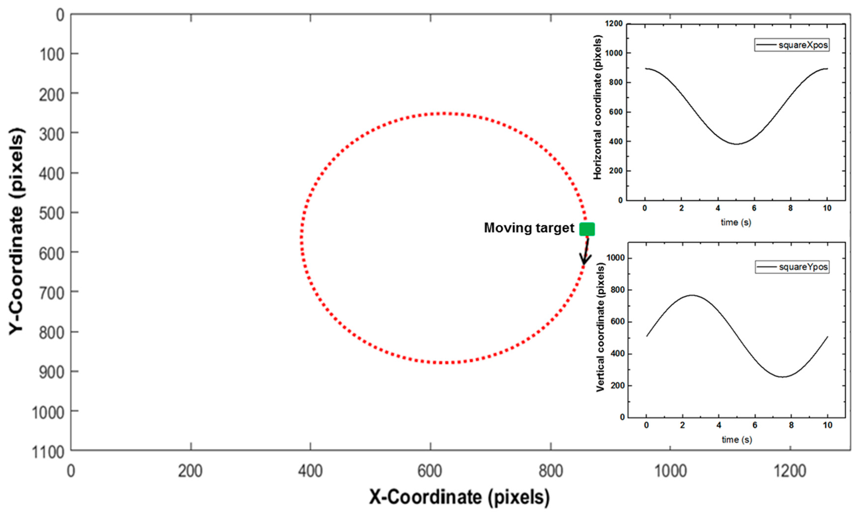
The stimulus is a green square of 5 by 5 pixels (moving target) which circulates around the center x-y coordinate of the monitor (640, 480). Figure 9 inset (top right) shows x-axis movement positions of the moving target on a full cycle. Figure 9 inset (bottom right) shows the y-axis movement positions of the moving target on a full cycle. According to our monitor specifications, initial values for calculation of moving target positions are presented in Table 1.
The stimulus (moving target) x and y axes positions can be obtained as progress time (t) intervals from Equations (11) and (12), respectively.
Here, squareXpos and squareYpos correspond to x and y pixel coordinates of the moving target. xCenter is monitor center coordinates’ x pixel value (640) and yCenter is monitor center coordinates’ y pixel value (512). ‘A’ is maximum amplitude value (radius) between the monitor center coordinate and the moving target.
3. Experimental Results
Figure 10 shows the measurement of the luminosity in the experimental environment. The luminosity of the room was measured with Extech LT300 light meter (FLIR Systems, Wilsonville, OR, USA) and its value was observed to be 505 lux.
The experiment was tested with a desktop computer containing a 3.4-GHz Intel® core™ i7-3770 K CPU and 16 GB of RAM. The monitor resolution was 1280 × 1024. In addition, an 850-nm illuminator group was used. The camera was positioned right below the center of the monitor, and the illuminator was also positioned below the center of the monitor. The distance (L) between the monitor and the user was roughly 700 mm. We tested our gaze tracking system with 11 participants whose ages were between 25 and 40. We performed the experiments with minimum 400 images per participant. Experimental results showed that the system can process 2046 × 1086 pixel images at 40 fps. Performance of the system compared to 640 × 480 pixel eye trackers, is approximately 280 fps as shown in Figure 11.
To estimate eye gaze points, first users were asked to look at calibration points. Nine calibration points are not visible to users on the user screen simultaneously. When calibration starts, the first calibration point is seen on the screen. Then, users have to press PC mouse to see other calibration points. After nine points calibration ends up, users track at least one cycle movement of the moving target stimulus. Afterwards, we estimate that system accuracy is offline. Figure 12 shows gaze point estimation geometry of our stimulus.
In general, the difference between the estimated (Sx, Sy) and the actual (S’) gaze point coordinates is expressed as the error amount of the gaze tracking system as shown in Equation (14). Here, corresponds to error amount, L is the user to screen distance and E(Sx,y) is Euclidean distance between estimated gaze point and the actual user screen coordinates. Equation (15) depicts absolute distance (D) of the estimated gaze position (Sx, Sy) from stimulus center coordinates in pixel. Equations (16) and (17) are estimated gaze point (Sx, Sy) x-axis deviation (Edx) and y-axis deviation (Edy) from gazed point (S’) actual coordinates. Finally, Equation (18) gives the expression of Euclidean error E(Sx,y) between estimated gaze point and actual user screen coordinates.
To calculate the accuracy of the system in degrees, the error amount in pixels requires conversion to mm unit. For this conversion, we multiplied pixel size of our monitor (0.29 mm) with the errors Edx and Edy. Then the x-axis, y-axis and Euclidean errors in degrees are calculated with Equations (19)–(21).
Eleven users participated in our system test and the calculated accuracy of the system is presented in Table 2 and Table 3. The results show that the average accuracy for both eyes are smaller than 1° which is accepted well among eye tracker studies. The calculated mean square error (MSE) and root mean square error (RMSE) of the system is presented in Table 4 and Table 5 respectively.
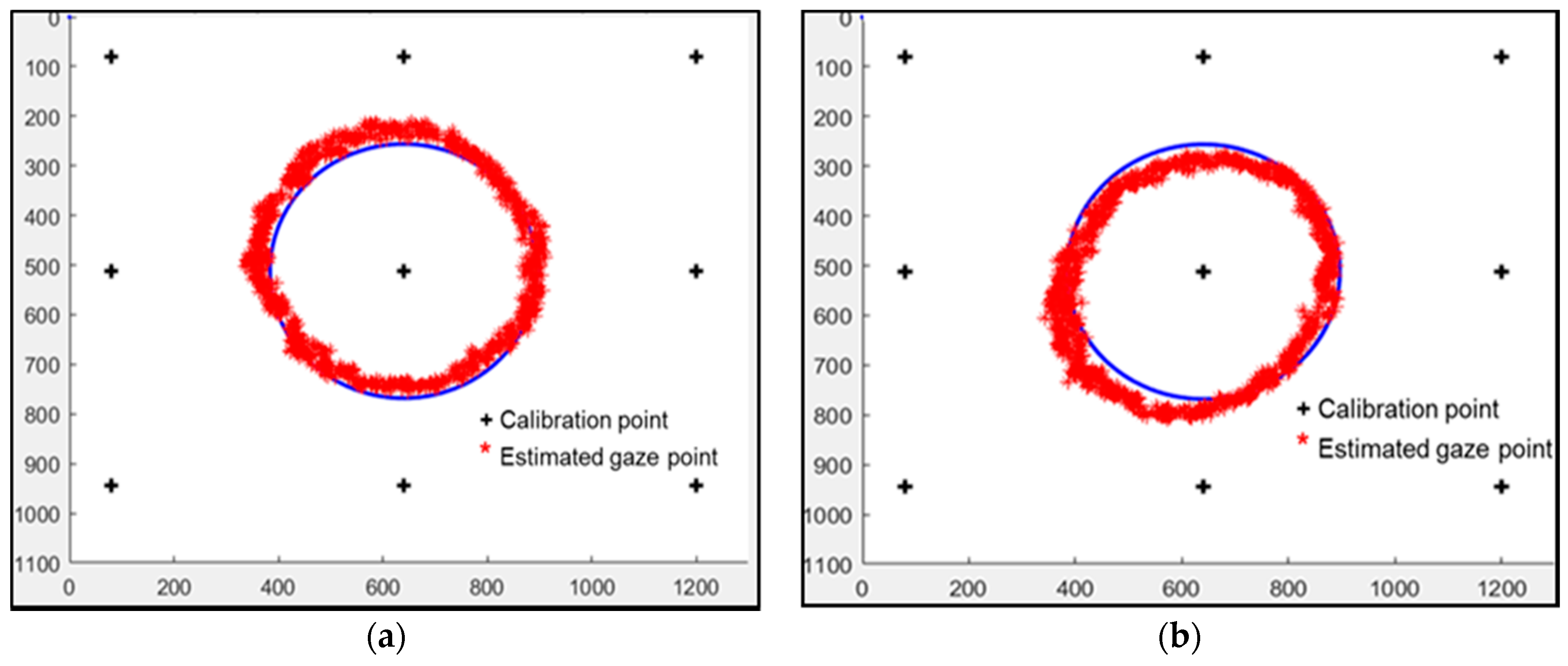
According to estimated gaze points of user 1, Figure 13 shows left and right eye tracking graphics on the stimulus signal.
4. Conclusions
In this study, we proposed a new binocular full HD resolution eye gaze tracking system using LabVIEW (LabVIEW 2015, National Instruments Corporation, Austin, TX, USA) image processing algorithms. The experimental results show that average error of the gaze estimation system is 0.83 degree on a 1280 × 1024 pixel resolution user monitor. The system working frequency is 40 Hz. According to the systems utilizing 640 × 480 size images, our result corresponds to 280 fps approximately. We preferred fast binary image processing algorithms to achieve this frequency. After binarization, pupil area is made clearer with morphological methods, and center coordinates of pupil and corneal reflections are found with the weighted average technique which is implemented faster than elliptic and circular shape detection methods. Therefore, the reactions of pupil depending on the stimulus can be observed at small time slices. This kind of fast eye tracker system finds its use in many practical applications such as human computer interaction, aviation, medicine, robot control, production tests and augmented reality.
The system works under a camera viewing angle. Head movement area width is 38.42 cm and height is 29.37 cm. Eye pupil and corneal reflections can be detected in this area. This is a limitation of the system. The design was tested with 11 participants. One of the participants was a contact lens user. The user’s eye pupil and corneal reflections were detected without problems. Reflections caused by the NIR illuminator and environment illumination can occur on the glass depending on eyeglass materials. To test the system for eyeglass users, each set of eyeglasses requires testing. The design has the ability to adjust threshold value and the size of reflections in the software. Therefore, the system could handle eyeglasses.
In the future, we will study another method to increase the accuracy and we will try to implement image processing algorithms into our FPGA frame grabber card to overcome operating system delays and tracking frequency.
Acknowledgments
This research was supported by coordinatorship of scientific research projects of Ankara University (13B4343008).
Author Contributions
All authors contributed to this collaborative work. Yilmaz Durna and Fikret Ari conceived and designed the experiments; Yilmaz Durna performed the experiments; Yilmaz Durna and Fikret Ari analyzed the data; Yilmaz Durna and Fikret Ari performed the research and discussed the results. Yilmaz Durna wrote the paper and Fikret Ari contributed to the writing and revision of the paper. All authors approved the manuscript.
Conflicts of Interest
The authors declare no conflict of interest.
References
- Wang, J.; Zhang, G.; Shi, J. Pupil and glint detection using wearable camera sensor and near-infrared LED array. Sensors 2015, 15, 30126–30141. [Google Scholar] [CrossRef] [PubMed]
- NeoMam Studios. Available online: http://neomam.com/interactive/13reasons (accessed on 15 December 2016).
- Tobii Pro. Available online: http://www.tobiipro.com/about/new-to-eye-tracking (accessed on 15 December 2016).
- Hyoki, K.; Shigeta, M.; Tsuno, N.; Kawamuro, Y.; Kinoshita, T. Quantitative electro-oculography and electroencephalography as indices of alertness. Electroencephalogr. Clin. Neurophysiol. 1998, 106, 213–219. [Google Scholar] [CrossRef]
- Robinson, D.A. A method of measuring eye movements using a scleral search coil in a magnetic field. IEEE Trans. Biomed. Eng. 1963, 10, 137–145. [Google Scholar] [PubMed]
- Duchowski, A.T. A Breadth-first survey of eye tracking applications. Behav. Res. Methods Instrum. Comput. 2002, 34, 455–470. [Google Scholar] [CrossRef] [PubMed]
- Yarbus, A.L. Eye Movements and Vision; Plenum Press: New York, NY, USA, 1967. [Google Scholar]
- Dodge, R.; Cline, T.S. The angle velocity of eye movements. Psychol. Rev. 1901, 8, 145–157. [Google Scholar] [CrossRef]
- Lai, C.C.; Shih, S.W.; Hung, Y.P. Hybrid method for 3-D gaze tracking using glint and contour features. IEEE Trans. Circuits Syst. Video Technol. 2015, 25, 24–37. [Google Scholar]
- Blignaut, P. Mapping the pupil-glint vector to gaze coordinates in a simple video-based eye tracker. J. Eye Mov. Res. 2014, 7, 1–11. [Google Scholar]
- Lee, J.W.; Heo, H.; Park, K.R. A novel gaze tracking method based on the generation of virtual calibration points. Sensors 2013, 13, 10802–10822. [Google Scholar] [CrossRef] [PubMed]
- Heo, H.; Lee, J.M.; Jung, D.; Lee, J.W.; Park, K.R. Nonwearable gaze tracking system for controlling home appliance. Sci. World J. 2014, 2014, 1–20. [Google Scholar] [CrossRef] [PubMed]
- Lee, H.C.; Lee, W.O.; Cho, C.W.; Gwon, S.Y.; Park, K.R.; Lee, H.; Cha, J. Remote gaze tracking system on a large display. Sensors 2013, 13, 13439–13463. [Google Scholar] [CrossRef] [PubMed]
- Morimoto, C.H.; Mimica, M.R.M. Eye gaze tracking techniques for interactive applications. Comput. Vis. Image Underst. 2005, 98, 4–24. [Google Scholar] [CrossRef]
- Sesma-Sanchez, L.; Villanueva, A.; Cabeza, R. Gaze estimation interpolation methods based on binocular data. IEEE Trans. Biomed. Eng. 2012, 59, 2235–2243. [Google Scholar] [CrossRef] [PubMed]
- Hennessey, C.A.; Lawrence, P.D. Improving the accuracy and reliability of remote system-calibration-free eye-gaze tracking. IEEE Trans. Biomed. Eng. 2009, 56, 1891–1900. [Google Scholar] [CrossRef] [PubMed]
- Cho, C.W.; Lee, J.W.; Lee, E.C.; Park, K.R. Robust gaze-tracking method by using frontal-viewing and eye-tracking cameras. Opt. Eng. 2009, 48, 127202. [Google Scholar] [CrossRef]
- Bang, J.W.; Lee, E.C.; Park, K.R. New computer interface combining gaze tracking and brainwave measurements. IEEE Trans. Consum. Electron. 2011, 57, 1646–1651. [Google Scholar] [CrossRef]
- Zhu, Z.; Ji, Q. Eye and gaze tracking for interactive graphic display. Mach. Vis. Appl. 2004, 15, 139–148. [Google Scholar] [CrossRef]
- Shih, S.W.; Liu, J. A novel approach to 3-D gaze tracking using stereo cameras. IEEE Trans. Syst. Man Cybern. 2004, 34, 234–245. [Google Scholar] [CrossRef]
- Fuhl, W.; Santini, T.C.; Kübler, T.; Kasneci, E. Else: Ellipse selection for robust pupil detection in real-world environments. In Proceedings of the Ninth Biennial ACM Symposium on Eye Tracking Research & Applications, Charleston, SC, USA, 14–17 March 2016; pp. 123–130. [Google Scholar]
- Fuhl, W.; Kübler, T.; Sippel, K.; Rosenstiel, W.; Kasneci, E. Excuse: Robust pupil detection in real-world scenarios. In Proceedings of the International Conference on Computer Analysis of Images and Patterns, Valletta, Malta, 2–4 September 2015; pp. 39–51. [Google Scholar]
- Fuhl, W.; Santini, T.; Kasneci, G.; Kasneci, E. PupilNet: Convolutional neural networks for robust pupil detection. arXiv, 2016; arXiv:1601.04902. [Google Scholar]
- Fuhl, W.; Tonsen, M.; Bulling, A.; Kasneci, E. Pupil detection for head-mounted eye tracking in the wild: An evaluation of the state of the art. Mach. Vis. Appl. 2015, 27, 1275–1288. [Google Scholar] [CrossRef]
- Sigut, J.; Sidha, S.A. Iris center corneal reflection method for gaze tracking using visible light. IEEE Trans. Biomed. Eng. 2011, 58, 411–419. [Google Scholar] [CrossRef] [PubMed]
- Guestrin, E.D.; Eizenman, M. General theory of remote gaze estimation using the pupil center and corneal reflections. IEEE Trans. Biomed. Eng. 2006, 53, 1124–1133. [Google Scholar] [CrossRef] [PubMed]
- Gonzalez, R.C.; Woods, R.E. Digital Image Processing, 3rd ed.; Pearson/Prentice Hall: Upper Saddle River, NJ, USA, 2008. [Google Scholar]
- Wilhelm, H.; Wilhelm, B. Clinical applications of pupillography. J. Neuroophthalmol. 2003, 23, 42–49. [Google Scholar] [CrossRef] [PubMed]
- Souza, J.K.S.; Pinto, M.A.; Vieira, P.G.; Baron, J.; Tierra-Criollo, C.J. An open-source, FireWire camera-based, Labview-controlled image acquisition system for automated, dynamic pupillometry and blink detection. Comput. Methods Progr. Biomed. 2013, 112, 607–623. [Google Scholar] [CrossRef] [PubMed]
- Alghowinem, S.; AlShehri, M.; Goecke, R.; Wagner, M. Exploring eye activity as an ındication of emotional states using an eye-tracking sensor. Intell. Syst. Sci. Inf. 2014, 542, 261–276. [Google Scholar]
- Tobii. Available online: http://www.tobiipro.com/product-listing (accessed on 15 February 2017).
- SMI. Available online: https://www.smivision.com/products (accessed on 15 February 2017).
- Gwon, S.Y.; Cho, C.W.; Lee, H.C.; Lee, W.O.; Park, K.R. Gaze tracking system for user wearing glasses. Sensors 2014, 14, 2110–2134. [Google Scholar] [CrossRef] [PubMed]
- Lee, J.M.; Lee, H.C.; Gwon, S.Y.; Jung, D.; Pan, W.; Cho, C.W.; Park, K.R.; Kim, H.-C.; Cha, J. A new gaze estimation method considering external light. Sensors 2015, 15, 5935–5981. [Google Scholar] [CrossRef] [PubMed]
- User’s Manual for Camera Link Cameras; Version 04; Basler: Ahrensburg, Germany, 2013.
- NI. Available online: http://www.ni.com/en-tr/support/model.pcie-1473.html (accessed on 15 February 2017).
- OSRAM. IEC 62471: Photobiological Safety of Lamps and Lamp Systems; OSRAM: Garching, Germany, 2006. [Google Scholar]
- Brainard, D.H. The psychophysics toolbox. Spat. Vis. 1997, 10, 433–436. [Google Scholar] [CrossRef] [PubMed]
- Pelli, D.G. The VideoToolbox software for visual psychophysics: Transforming numbers into movies. Spat. Vis. 1997, 10, 437–442. [Google Scholar] [CrossRef] [PubMed]
- Kleiner, M.; Brainard, D.; Pelli, D. What’s new in Psychtoolbox-3. Perception 2007, 36, 1–16. [Google Scholar]
Figure 1.
Proposed eye gaze tracking system. IR: infrared.

Figure 2.
infrared (IR) illuminator location around eye capture camera. (a) Dark pupil effect; (b) Bright pupil effect.
Figure 2.
infrared (IR) illuminator location around eye capture camera. (a) Dark pupil effect; (b) Bright pupil effect.

Figure 3.
Filter modification of Basler acA2000-340kc camera.
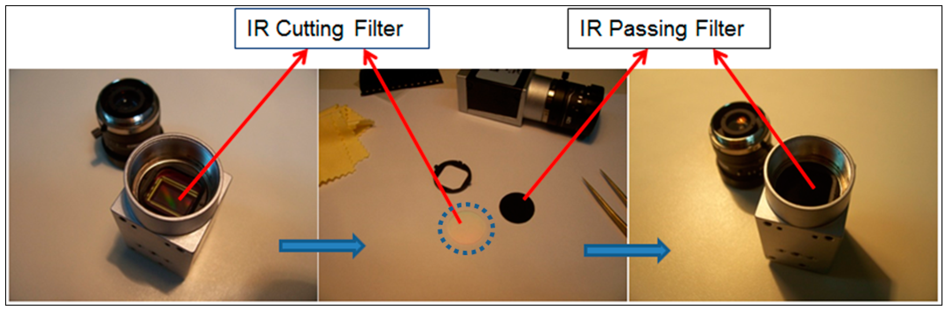
Figure 4.
IR passing and IR cutting filter spectral responses of Basler acA2000-340kc camera.
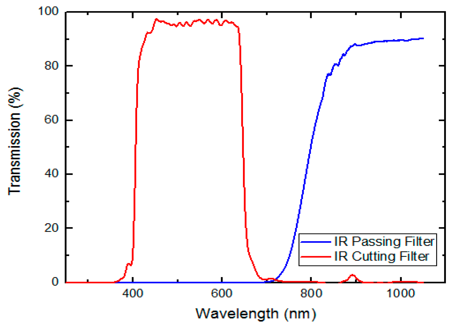
Figure 5.
Flow chart of eye gaze tracking system. region of interest (ROI): region of interest.

Figure 6.
User interface menu of the LabVIEW-based eye tracker.
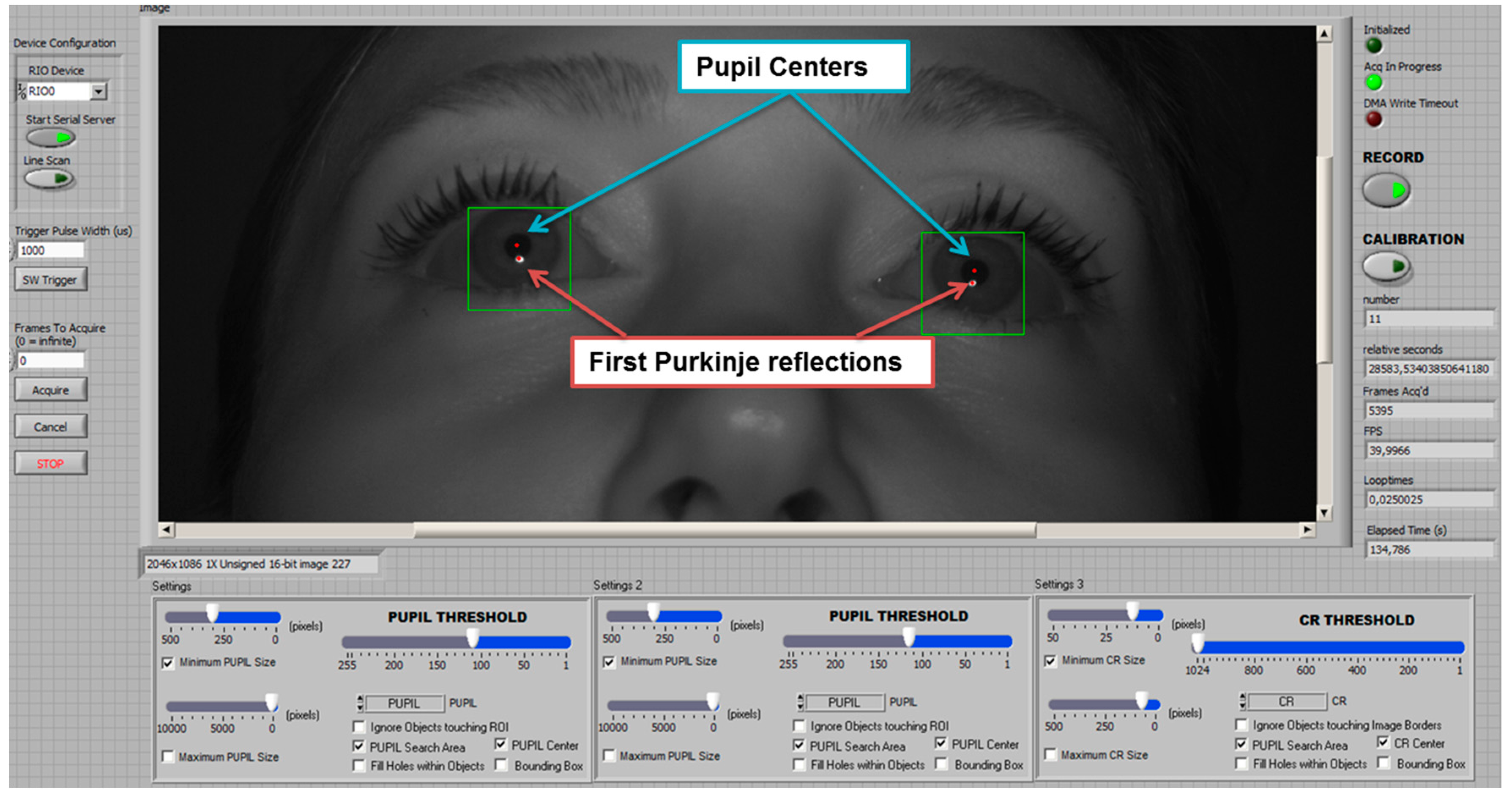
Figure 7.
The glint and pupil center region detection process: (a) Eye region extracted from original image; (b) Binarization of gray level image for glint; (c) Application of morphological filter to the glint; (d) Weighted average technique applied to the glint; (e) Application of binarization to the pupil image; (f) Application of morphological filter to the pupil; (g) Application of weighted average technique to the pupil; (h) Pupil and glint detection of two eyes in the face image.

Figure 8.
User calibration points of the eye gaze tracker.

Figure 9.
User stimulus signal (red dotted circle). Inset (top right): x-axis movement positions of moving target on a full cycle. Inset (bottom right): y-axis movement positions of moving target on a full cycle.
Figure 9.
User stimulus signal (red dotted circle). Inset (top right): x-axis movement positions of moving target on a full cycle. Inset (bottom right): y-axis movement positions of moving target on a full cycle.

Figure 10.
The luminosity measurement of the experimental environment.
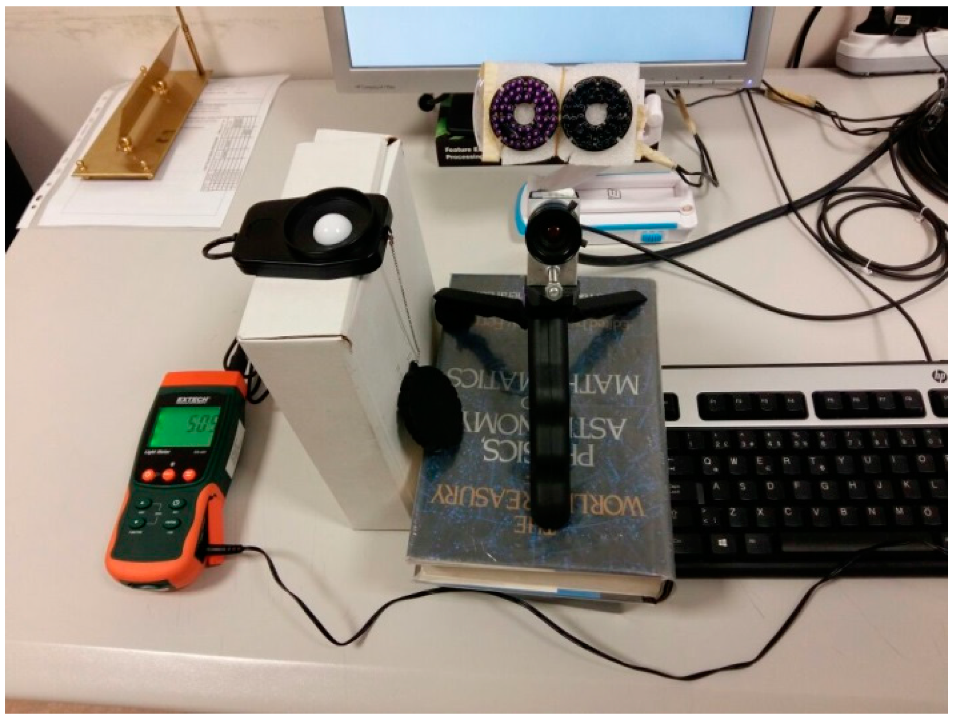
Figure 11.
The system performance. fps: frames per second.
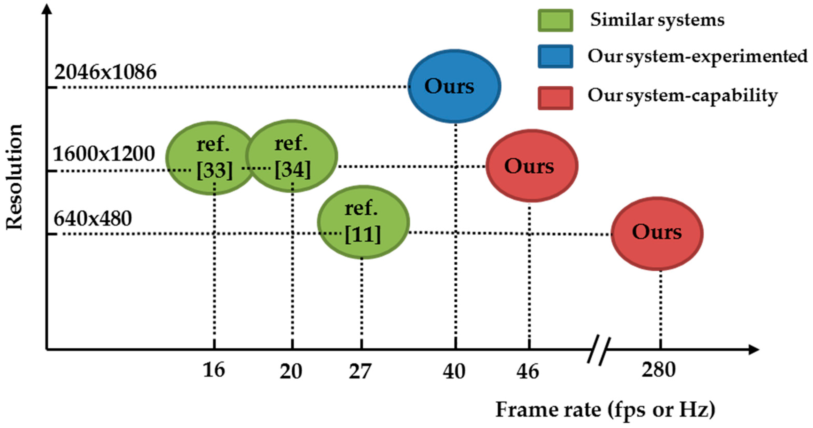
Figure 12.
Gaze point estimation geometry on the user screen.
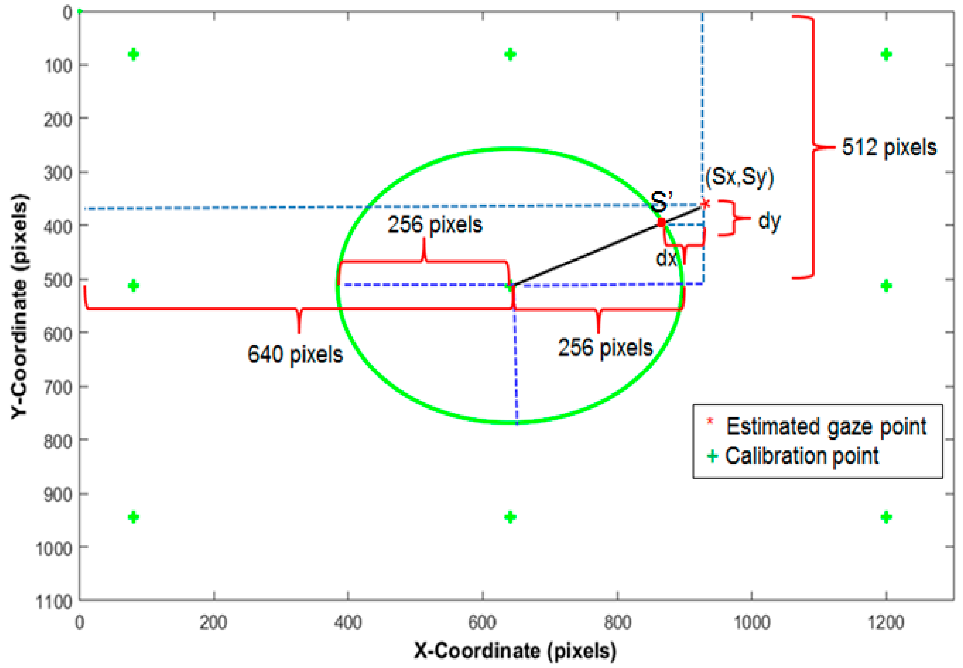
Figure 13.
(a) Right eye estimated gaze points tracking the stimulus signal; (b) Left eye estimated gaze points tracking the stimulus signal. Note that blue circle represents cycle of the moving target.
Figure 13.
(a) Right eye estimated gaze points tracking the stimulus signal; (b) Left eye estimated gaze points tracking the stimulus signal. Note that blue circle represents cycle of the moving target.


Table 1.
Moving target initial values.
| Initial Parameters | Value | Unit |
|---|---|---|
| Stimulus center x-coordinate (xCenter) | 640 | pixel |
| Stimulus center y-coordinate (yCenter) | 512 | pixel |
| Stimulus radius (A) | 256 | pixel |
| 33Angular frequency (w) | 2 × π × 0.1 | rad/s |
| Progress start time () | 0 | s |
| Refresh rate of monitor (rt) | 16.6 | ms |
| Phase ( | 0 | rad |
Table 2.
Estimation results of gaze tracking accuracies in degrees. MSE: mean square error.
| Users | Right Eye x Axis Error (°) | Right Eye y Axis Error (°) | Euclidean Right Eye Error (°) | Left Eye x Axis Error (°) | Left Eye y Axis Error (°) | Euclidean Left Eye Error (°) | Mean Error of Both Eyes (°) |
|---|---|---|---|---|---|---|---|
| User 1 | 0.50 | 0.55 | 0.81 | 0.31 | 0.31 | 0.49 | 0.65 |
| User 2 | 0.58 | 0.37 | 0.77 | 0.35 | 0.22 | 0.46 | 0.61 |
| User 3 | 0.50 | 0.39 | 0.69 | 0.99 | 0.81 | 1.43 | 1.06 |
| User 4 | 0.77 | 0.78 | 1.11 | 0.47 | 0.38 | 0.65 | 0.88 |
| User 5 | 0.70 | 0.98 | 1.31 | 0.68 | 0.35 | 0.84 | 1.08 |
| User 6 | 0.49 | 0.51 | 0.80 | 0.59 | 0.64 | 0.97 | 0.88 |
| User 7 | 0.30 | 0.33 | 0.51 | 0.35 | 0.41 | 0.60 | 0.55 |
| User 8 | 0.45 | 0.57 | 0.79 | 0.47 | 0.57 | 0.80 | 0.80 |
| User 9 | 1.02 | 1.63 | 2.11 | 0.45 | 0.83 | 1.03 | 1.57 |
| User 10 | 0.35 | 0.28 | 0.49 | 0.39 | 0.29 | 0.55 | 0.52 |
| User 11 | 0.29 | 0.30 | 0.46 | 0.38 | 0.39 | 0.59 | 0.53 |
| Average | 0.54 | 0.60 | 0.89 | 0.49 | 0.47 | 0.76 | 0.83 |
Table 3.
Estimation results of gaze tracking accuracies in mm.
| Users | Right Eye x Axis Error (mm) | Right Eye y Axis Error (mm) | Euclidean Right Eye Error (mm) | Left Eye x Axis Error (mm) | Left Eye y Axis Error (mm) | Euclidean Left Eye Error (mm) | Mean Error of Both Eyes (mm) |
|---|---|---|---|---|---|---|---|
| User 1 | 6.06 | 6.75 | 9.85 | 3.76 | 3.77 | 5.95 | 7.90 |
| User 2 | 7.03 | 4.56 | 9.36 | 4.27 | 2.64 | 5.56 | 7.46 |
| User 3 | 6.12 | 4.80 | 8.47 | 12.10 | 9.85 | 17.42 | 12.94 |
| User 4 | 9.46 | 9.54 | 13.61 | 5.73 | 4.58 | 7.99 | 10.80 |
| User 5 | 8.60 | 11.92 | 16.05 | 8.32 | 4.30 | 10.23 | 13.14 |
| User 6 | 6.04 | 6.18 | 9.79 | 7.19 | 7.77 | 11.80 | 10.79 |
| User 7 | 3.62 | 4.07 | 6.22 | 4.31 | 5.05 | 7.33 | 6.77 |
| User 8 | 5.45 | 6.96 | 9.68 | 5.73 | 6.99 | 9.76 | 9.72 |
| User 9 | 12.48 | 19.85 | 25.78 | 5.54 | 10.09 | 12.57 | 19.17 |
| User 10 | 4.27 | 3.41 | 6.04 | 4.76 | 3.56 | 6.67 | 6.36 |
| User 11 | 3.52 | 3.64 | 5.66 | 4.64 | 4.71 | 7.24 | 6.45 |
| Average | 6.60 | 7.42 | 10.95 | 6.03 | 5.75 | 9.32 | 10.13 |
Table 4.
Estimation results of gaze tracking mean square errors in degrees.
| Users | Right Eye x Axis MSE (°) | Right Eye y Axis MSE (°) | Euclidean Right Eye MSE (°) | Left Eye x Axis MSE (°) | Left Eye y Axis MSE (°) | Euclidean Left Eye MSE (°) | Mean MSE of Both Eyes (°) |
|---|---|---|---|---|---|---|---|
| User 1 | 1.064 | 1.953 | 2.533 | 0.154 | 0.180 | 0.335 | 1.434 |
| User 2 | 0.071 | 0.078 | 0.150 | 0.071 | 0.025 | 0.097 | 0.123 |
| User 3 | 0.164 | 0.110 | 0.275 | 0.968 | 0.963 | 1.930 | 1.102 |
| User 4 | 0.221 | 0.284 | 0.506 | 0.168 | 0.117 | 0.285 | 0.395 |
| User 5 | 0.830 | 1.881 | 2.710 | 0.943 | 0.183 | 1.127 | 1.918 |
| User 6 | 0.257 | 0.607 | 0.864 | 0.450 | 0.417 | 0.867 | 0.865 |
| User 7 | 0.184 | 0.247 | 0.432 | 0.229 | 0.360 | 0.589 | 0.510 |
| User 8 | 0.322 | 0.585 | 0.908 | 0.344 | 0.541 | 0.876 | 0.892 |
| User 9 | 0.741 | 4.577 | 5.316 | 0.320 | 1.577 | 1.897 | 3.606 |
| User 10 | 0.225 | 0.186 | 0.412 | 0.238 | 0.125 | 0.363 | 0.389 |
| User 11 | 0.136 | 0.158 | 0.294 | 0.222 | 0.241 | 0.464 | 0.379 |
| Average | 0.383 | 0.969 | 1.309 | 0.373 | 0.429 | 0.802 | 1.055 |
Table 5.
Estimation results of gaze tracking root mean square errors (RMSE) in degrees.
| Users | Right Eye x Axis RMSE (°) | Right Eye y Axis RMSE (°) | Euclidean Right Eye RMSE (°) | Left Eye x Axis RMSE (°) | Left Eye y Axis RMSE (°) | Euclidean Left Eye RMSE (°) | Mean RMSE of Both Eyes (°) |
|---|---|---|---|---|---|---|---|
| User 1 | 1.031 | 1.397 | 1.591 | 0.393 | 0.425 | 0.579 | 1.085 |
| User 2 | 0.267 | 0.280 | 0.387 | 0.267 | 0.160 | 0.312 | 0.349 |
| User 3 | 0.406 | 0.331 | 0.524 | 0.983 | 0.981 | 1.389 | 0.956 |
| User 4 | 0.470 | 0.533 | 0.711 | 0.409 | 0.342 | 0.533 | 0.622 |
| User 5 | 0.911 | 1.371 | 1.646 | 0.971 | 0.428 | 1.061 | 1.353 |
| User 6 | 0.507 | 0.779 | 0.930 | 0.671 | 0.645 | 0.931 | 0.930 |
| User 7 | 0.430 | 0.497 | 0.657 | 0.478 | 0.600 | 0.767 | 0.712 |
| User 8 | 0.568 | 0.765 | 0.953 | 0.578 | 0.736 | 0.936 | 0.944 |
| User 9 | 0.861 | 2.139 | 2.305 | 0.565 | 1.255 | 1.377 | 1.841 |
| User 10 | 0.475 | 0.431 | 0.642 | 0.488 | 0.354 | 0.603 | 0.622 |
| User 11 | 0.368 | 0.398 | 0.542 | 0.472 | 0.491 | 0.681 | 0.611 |
| Average | 0.572 | 0.811 | 0.989 | 0.570 | 0.583 | 0.833 | 0.911 |
© 2017 by the authors. Licensee MDPI, Basel, Switzerland. This article is an open access article distributed under the terms and conditions of the Creative Commons Attribution (CC BY) license (http://creativecommons.org/licenses/by/4.0/).
Share and Cite
MDPI and ACS Style
Durna, Y.; Ari, F. Design of a Binocular Pupil and Gaze Point Detection System Utilizing High Definition Images. Appl. Sci. 2017, 7, 498. https://doi.org/10.3390/app7050498
AMA Style
Durna Y, Ari F. Design of a Binocular Pupil and Gaze Point Detection System Utilizing High Definition Images. Applied Sciences. 2017; 7(5):498. https://doi.org/10.3390/app7050498
Chicago/Turabian StyleDurna, Yilmaz, and Fikret Ari. 2017. "Design of a Binocular Pupil and Gaze Point Detection System Utilizing High Definition Images" Applied Sciences 7, no. 5: 498. https://doi.org/10.3390/app7050498
Note that from the first issue of 2016, this journal uses article numbers instead of page numbers. See further details here.