
Variable Pole Pitch Electromagnetic Propulsion with Ladder-Slot-Secondary Double-Sided Linear Induction Motors

School of Electrical Engineering, Beijing Jiaotong University, Beijing 100044, China
*
Author to whom correspondence should be addressed.
Appl. Sci. 2017, 7(5), 481; https://doi.org/10.3390/app7050481
Submission received: 28 February 2017
/
Revised: 27 April 2017
/
Accepted: 28 April 2017
/
Published: 6 May 2017
(This article belongs to the Section Energy Science and Technology)
Abstract
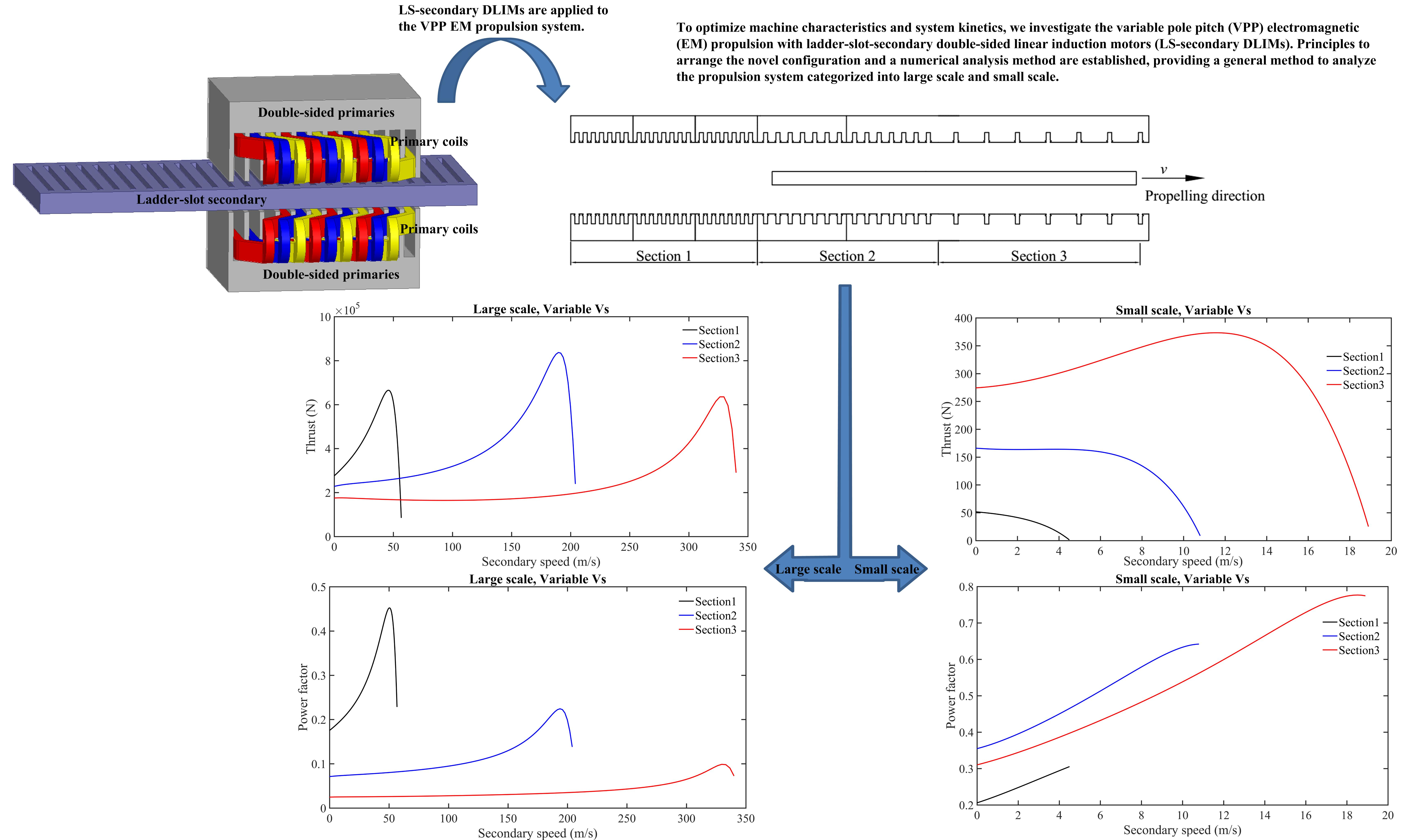
:In this paper, we propose a novel variable pole pitch (VPP) electromagnetic (EM) propulsion technique using a series of ladder-slot-secondary double-sided linear induction motors (LS-secondary DLIMs). An equivalent circuit is developed for the LS-secondary DLIM, which considers the distribution of the eddy current in the ladders and the end effect. This equivalent circuit forms the basis for the subsequent design, numerical analysis, and optimization. The primary purpose of the VPP EM propulsion system is to address several obstacles encountered in high-speed large-thrust applications of LIMs, such as power factor improvement, optimization considering supply frequency constraint and operating kinetics, etc. The equivalent circuit of the LS-secondary DLIM, i.e., the theoretical foundation of the VPP EM propulsion, has been validated via simulation and experimentation on a small-scale platform, which proves that the numerical analysis of the VPP EM propulsion is effective.

1. Introduction
Linear induction motors (LIMs) have been applied to high-speed large-thrust electromagnetic (EM) propulsion applications, such as EM launch [1] and transportation systems [2]. Nevertheless, when the power is increased beyond a certain point, certain detrimental characteristics of LIMs, especially the power factor, are magnified [3]. Meanwhile, as the speed increases, the burden on the power supply system also increases, and the frequency of power electronic devices consequently limits the supply frequency and restricts the acceleration [4].
To balance the heavy burden on supply devices with the growing kinetic requirements, a variable pole pitch (VPP) EM propulsion scheme was proposed in [5,6] and a VPP EM system propelled by a flat-secondary LIM was analyzed. However, when the challenges with typical LIMs are considered, such as low power factor, it is clear that previous VPP EM propulsion techniques suffer from poor performance as the input power increases [7]. To address those problems, we propose a VPP EM propulsion scheme using ladder-slot-secondary double-sided linear induction motors (LS-secondary DLIMs).
LS-secondary DLIMs are capable of enhancing the power factor, which can be calculated via the finite element method (FEM) in [8]. However, this approach is commonly considered to be a method of verifying the characteristics of a previously designed machine, instead of being a general method to design and analyze new machines. In addition, the derivation of the EM field in the motor leads to an accurate but complex model [9,10,11]. Squirrel-cage rotary induction motors (RIMs) have been extensively studied, and mathematical models, analytical design methods [12], and equivalent circuit analyses are readily available [13]. However, because of the end effect in DLIMs [14], the mathematical model developed for RIMs cannot be used. In the absence of general methods to design, analyze and optimize LS-secondary DLIMs in practical scenarios, it is extremely difficult to successfully implement a VPP EM propulsion scheme due to the complexity of the model and the enormity of calculations. To accomplish our objective of designing a VPP EM propulsion scheme, we first present a generic method for designing an LS-secondary DLIM.
In this paper, we propose a novel scheme for EM propulsion, i.e., the VPP EM propulsion using LS-secondary DLIMs, aiming at optimizing kinetic performance and enhancing machine characteristics simultaneously. A numerical analysis method is established based on equivalent circuit considering end effect of LS-secondary DLIMs. Due to applicability and generality of the equivalent circuit, the numerical analysis is a general method to design, estimate, and optimize the VPP EM propulsion using LS-secondary DLIMs. Consequently, this paper accomplishes the theoretical analysis of this novel EM propulsion scheme. This method is not only an effective and accurate method to estimate the performance of the novel configuration, but also utilization of LS-secondary DLIMs in the VPP EM propulsion may serve as a promising solution to high-speed large-thrust applications such as EM launch.
This paper is organized as follows. Section 2 presents an equivalent circuit model based on Duncan’s model [15] for a single LS-secondary DLIM. Meanwhile, referring to the EM field in our previous work [16], stress analysis is carried out to determine whether designed LS-secondary DLIMs are feasible in practical scenarios. Section 3 first establishes the VPP EM propulsion scheme using LS-secondary DLIMs. Theory of numerical analysis for this scheme is then proposed. Kinetic characteristics, such as the acceleration of each sectional motor, the overall displacement, and the performance period, are analyzed with the aid of the equivalent circuit-based model of the LS-secondary DLIM. After kinetic characteristics are numerically achieved, impacts of LS-secondary DLIMs on the VPP EM propulsion system are discussed in several aspects relative to practical factors, which are compared to a constant pole pitch (CPP) design. Section 4 presents FEM and experimental validation of numerical analysis. Section 5 provides a summary of the work.
2. Design and Numerical Analysis of the Ladder-Slot-Secondary Double-Sided Linear Induction Motors (LS-Secondary DLIM)
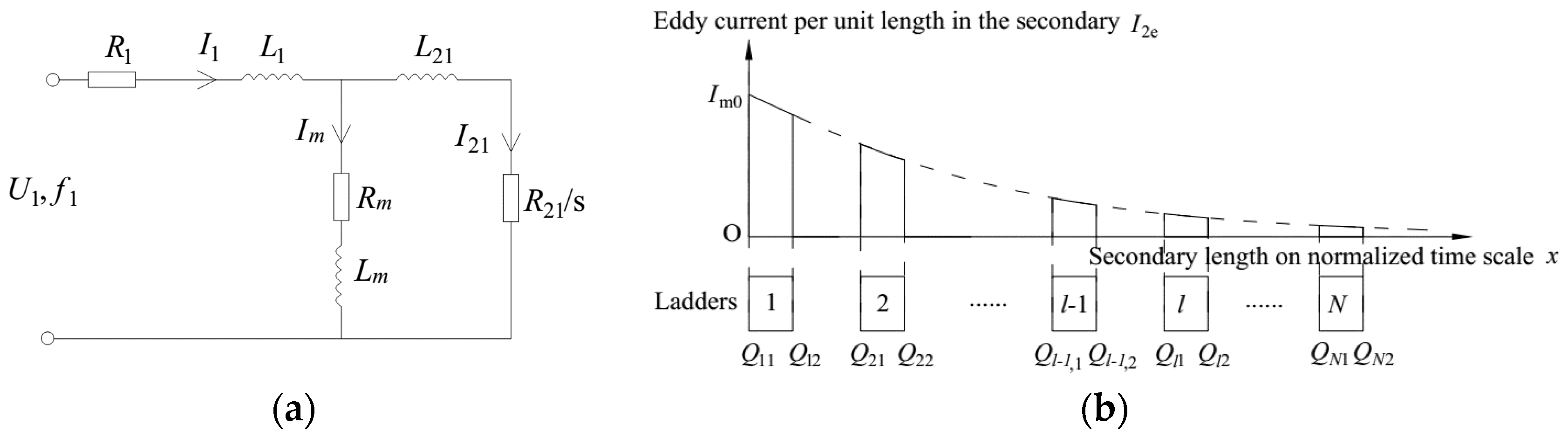
An LS-secondary DLIM differs from a flat-secondary DLIM in the structure of the secondary, as seen in Figure 1, which leads to differences in the EM field and eddy current in the secondary. As was discussed in [7], the longitudinal end effect is significant, while the transverse end effect is insignificant and can be ignored. Thus we only consider the longitudinal end effect when investigating the model of the LS-secondary DLIM. Meanwhile, the derivation of the EM field is so complex that it requires intensive computation. With these two factors in mind, we use Duncan’s model [15] to determine a more feasible solution while simultaneously maintaining the accuracy and effectiveness of the equivalent circuit. The parameters associated with Figure 1, as well as all other parameters used in this paper, are listed in Table A1.
2.1. Equivalent Circuit Considering the End Effect
When designing a single LS-secondary DLIM for EM propulsion, the secondary is assumed to be the same length as the primary. If the cogging ratio is defined as the ratio of the slot width to the ladder width, the slot width and the ladder width can be expressed as follows:
If Equation (1) is substituted into the equivalent circuit in Figure 2a, the model of the LS-secondary DLIM becomes a function of the cogging ratio.
Referring to Duncan’s model and considering the discrete ladders, the eddy current per unit length induced in the LS-secondary is shown in Figure 2b, the envelope of which is consistent with that in Duncan’s model [14]. A series of ladder ends on a normalized time scale is proposed as a modification of the time scale’s length. To simplify the formula, we define:
Thus, the series of ladder ends on a normalized time scale can be represented as:
Then we express the distribution of eddy current induced in the secondary as a function of Equation (2):
By applying segmental integration, the modified magnetizing inductance and magnetizing resistance can be written as:
It can be seen from Equation (4) that the longitudinal end effect influences the magnetizing inductance via the root-mean-square (RMS) value of the secondary eddy current, while it is the sole cause of the magnetizing and the secondary resistances.
On one hand, the secondary resistance referred to as primary R21 (as in Equation (5)), differs from that of the flat secondary, and consists of the resistance of the ladders RL and the resistance of end connections RS, both of which can be derived according to Kirchhoff’s law.
On the other hand, the magnetizing inductance without the end effect and the remaining inductances in the equivalent circuit can be derived from the inductances of the flat-secondary DLIM [7], as in Equation (6). The superscript f and coefficient Kc2 indicate the parameters of the flat-secondary DLIM and Carter’s coefficient, respectively.
In addition, the primary resistance remains the same as that of the flat-secondary DLIM. By combining the above six equations, we arrive at the equivalent circuit of the LS-secondary DLIM, upon which the ensuing numerical analysis is founded.
Here, we also discuss the distribution of the EM shear stress. Referring to the EM field in [16], the distribution of the flux density B and eddy current density J2 along the secondary ladders can be represented as follows:
where coefficients σ, μ0, J1, β, g, A1, A2, q1l, and q2l are as described in the definitions and equations shown in [16]. Then, the distribution of the EM shear stress yields:
As a consequence of the positive real part of A1 and A2, te has a maximum at the end of the secondary. However, the coefficients in Equations (7) and (8) are complex values, and indicate that the distribution of the EM shear stress is unsuitable for use when analyzing the LS-secondary DLIM in a series for application to the VPP EM propulsion scheme.
2.2. Numerical Analysis of Characteristics
In this paper, we focus on characteristics of the LS-secondary DLIM, including power factor and thrust. With the aid of Thevenin’s theorem, the overall equivalent impedance can be written as:
Then the numerical expressions of the characteristics are:
By substituting Equation (1) in the equivalent circuit parameters, characteristics in Equation (10) can be regarded as functions of the geometrical dimensions and secondary speed. The model’s properties, including cogging ratio, power factor, and secondary speed, have been discussed in detail in previous works [16]. However, in this paper, we are mostly concerned with the characteristic of the thrust and its related stresses. For the purpose of simplification, the thrust can be considered as evenly distributed on each ladder, and average EM shear stress on the secondary can be written as:
where Te,max represents the maximum value of the average EM shear stress, and can be utilized to determine whether the LS-secondary meets the requirement on EM shear stress [17].
Then, the maximum normal stress σmax, maximum shear stress τmax, and maximum deflection kmax on a single ladder, which are defined in structural analysis [18], can be expressed as:
where Estr represents the elastic modulus.
Although it may appear difficult to derive the analytical variation trend simply from the equivalent circuit, the aforementioned equations not only provide a numerical analysis method for the design of a single DLIM, they also serve as the theoretical basis from which to analyze the kinetics of VPP EM propulsion.
3. Variable Pole Pitch (VPP) Electromagnetic (EM) Propulsion
VPP EM propulsion differs from CPP EM propulsion in the arrangement of the propulsive machines. Unlike uniformly designed machines, VPP EM propulsion adopts a series of machines whose pole pitches are varied based on certain regular patterns. In this section, we investigate the patterns and associated calculations to determine how LS-secondary DLIMs in a series can be applied to VPP EM propulsion.
3.1. Arrangement of VPP DLIMs
We define the primaries with the same dimensions as a section of the EM propulsion, as shown in Figure 3. It is possible that one section may contain several primaries due to the kinetic requirements. Due to practical production and operational consideration, especially to circumvent the risk of adverse effects caused by altered slot combinations as the LS-secondary travels to other sections, several principles should be followed:
- The secondary dimensions, including the cogging ratio, ladder width, and slot width, should be remain constant during the whole operating process.
- The slot combination between the primary and secondary must be the same among sections.
- The primary width is maintained all along the propelling direction.
- The maximum synchronous speed of the LS-secondary DLIMs is the same as the terminal speed of the EM propulsion.
Thus, to realize variable pole pitch, the primary slots per pole per phase q should vary piecewise. Based on the design principles of the DLIM [19], the aforementioned principles lead to the following restrictions:
which result in two categories of VPP EM propulsion:
- Sections with a constant Vs, have the same synchronous speed.
- Sections with variable Vs, have different synchronous speeds.
The first category is applicable to sections with a constant Vs, and the Vs of the primaries in all sections are set to VT/(1−s). Since this arrangement avoids limiting the synchronous speed, the sections can be arranged for different kinetic optimization targets by altering their order.
In contrast, it is much more likely for sections with variable Vs to get better workouts on the supply frequency. When Vs < VT/(1−s) is assumed, the supply frequency of former sections will be reduced compared to those for the sections with a constant Vs. This category of VPP EM propulsion is suitable for the multi-target optimization of extremely high-speed large-thrust applications, especially EM launching systems, where the maximum frequency of the power electronic devices is more significant than the financial expense and operating space.
3.2. Numerical Analysis of VPP EM Propulsion
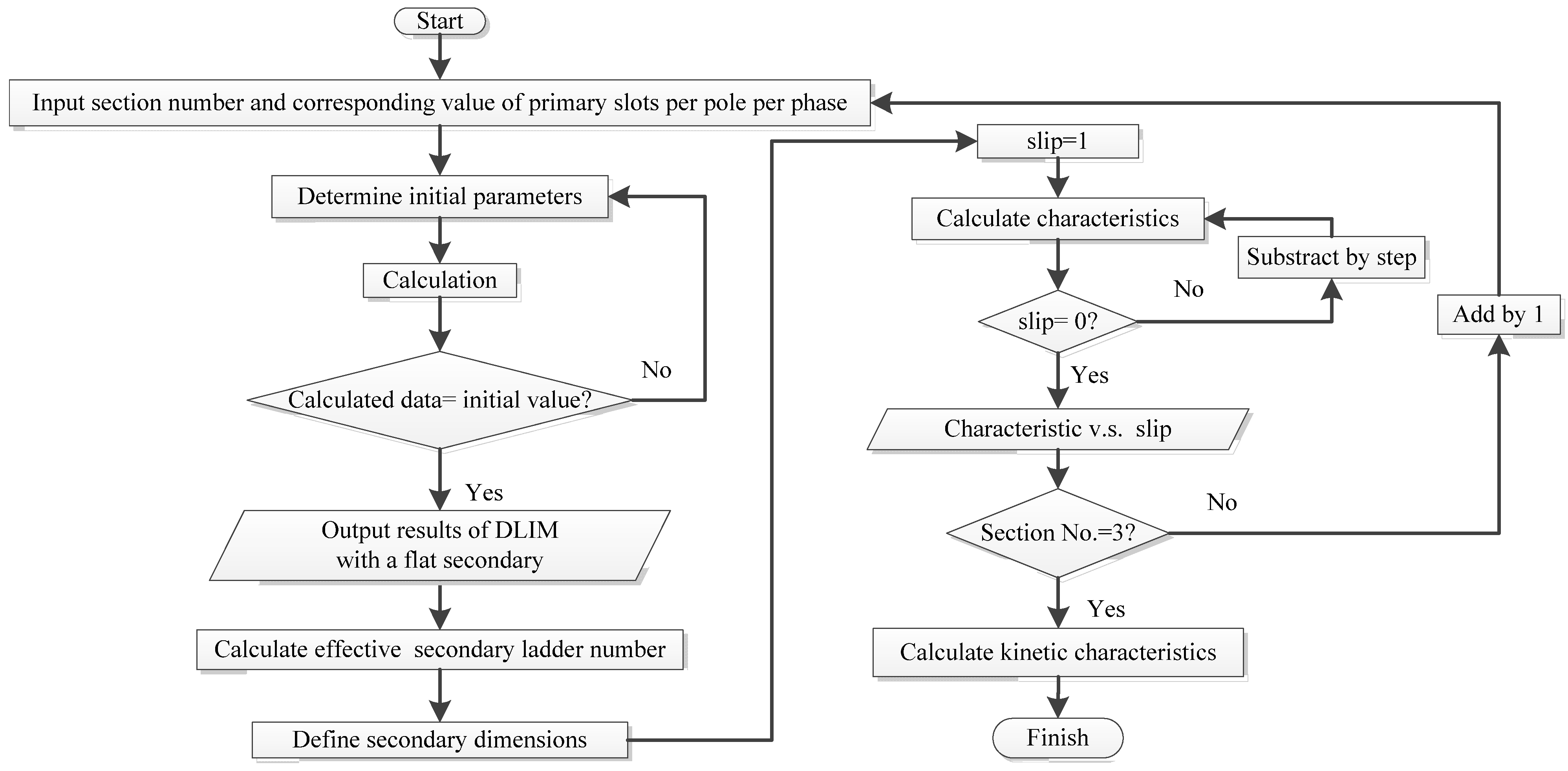
A flowchart to numerically analyze the kinetics of the VPP EM propulsion is presented in Figure 4. The numerical calculations in Figure 4 have been realized in MATLAB, including the design of the LS-secondary DLIM for each section and the analysis of their characteristics.
As part of the numerical analysis, we designed and calculated four configurations of VPP EM propulsion, which were classified into the four categories listed in Table 1. The analysis procedure followed that depicted in the flowchart in Figure 4. The VPP EM propulsion configurations were segmented into three sections, where Section 1 is the head while Section 3 is at the terminal end. The primary slots per pole per phase equaled to 1, 2, and 3, respectively.
The VPP EM propulsion system with a supply voltage of 10 kV was designed to meet the requirements of the EM launching system at VT = 0.8 Ma, with a loading mass of 24 t, while the system with a supply voltage of 220 V was intended for use in a small-scale platform. In practice, the small-scale DLIM can be used for applications in industrial mechanics that have restrictions in terms of the maintenance expense and supply frequency, which requires more limitation on both the maintenance expense and supply frequency, because back-and-forth translation tends to cause more ohmic losses in the core and higher risk of mechanical cutting in these occasions.
According to the theory of electrical machines, the thrust in each section is correlated with the secondary speed. Thus we can derive the kinetic characteristics, including the displacement and performance period, as follows:
Then a substitution in Equation (16) can be carried out in integration of the kinetic characteristics:
Therefore, the displacement and performance period of VPP EM propulsion yield in Equation (17):
where the subscript i represents the parameters belonging to the ith section. The kinetic characteristics in Table 1 were calculated using Equation (16).
In contrast to VPP EM propulsion, CPP EM propulsion adopts primaries in Section 3. The displacement of the CPP EM propulsion system with a supply voltage of 10 kV, and that for the one with a supply voltage of 220 V were 6064.36 m and 69.77 m, respectively, while the performance periods were 42.13 s and 6.32 s, respectively. By comparing the two types of EM propulsion, we concluded that VPP EM propulsion has better performance in large scale for both the supply frequency and kinetic characteristics. In contrast, the small-scale propulsion system exhibited mixed results when the VPP EM propulsion method was adopted, because the VPP EM propulsion method had makes less desirable kinetics, even though it led to an optimal improvement in the supply frequency, which ultimately results in lower ohmic losses.
The EM shear stress in Table 1 for each DLIM has been calculated via Equation (11). Since the DLIM usually operates with an EM shear stress of 70–100 kN/m2 [17], the machines in Table 1 are considered practical.
The structural parameters can be obtained from Equation (12). Owing to the principles of VPP EM propulsion and restrictions in Equations (13) and (14), the maximum structural parameters for the large-scale VPP EM propulsion will occur at Section 1 with variable Vs. Thus, the maximum values turn out to be: σmax = 75.0 MPa, τmax = 2.76 MPa and kmax = 4.59 mm. After comparison with the practical standard of an aluminum secondary, with tensile strength σb = 124 MPa, shear strength τb = 165 MPa, and permitted deflection kb = 0.05b2 = 5 mm, the LS-secondary DLIM seizing for the VPP EM propulsion system was shown to have met the structural requirements.
In summary, the performance of the VPP EM propulsion system changes depending on the operating conditions, and a numerical analysis is therefore essential. By referring to the numerical calculations of VPP EM propulsion, it can be determined whether the type of VPP matches the desired propulsion system and how best to optimize the system while taking into account the practical factors.
4. Simulation and Experiment
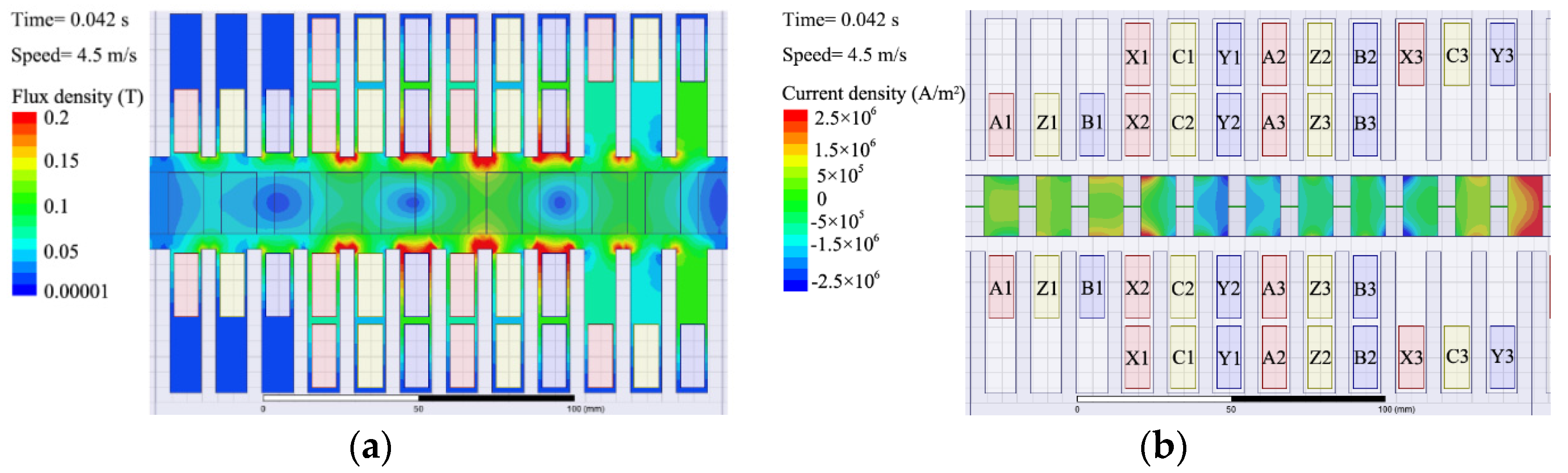
Since the numerical analysis of the VPP EM propulsion system is based on the design and numerical analysis of the LS-secondary DLIM, we now describe our validation of the equivalent circuit model. The intent of this experiment is to overcome the limited conditions in our laboratory, especially the lack of room to realize translational motion. Both the FEM simulation with Ansoft and the DLIM on the platform were designed according to DLIM parameters shown in Table A2, which are the same as those referenced in Section 1, namely, Vs = 4.5 m/s, in the VPP EM propulsion.
The distribution of the flux density and secondary eddy current, calculated in two-dimensional (2D) FEM, are shown in Figure 5, indicating that the LS-secondary DLIM operates in unsaturated condition. Figure 5b shows the distribution of secondary eddy current induced by three-phase space vector synthesis of primary excitations, which gradually decreases in each ladder along the motion direction, in accordance with the distribution of eddy current amplitude referred to as Duncan’s model in Figure 2b.
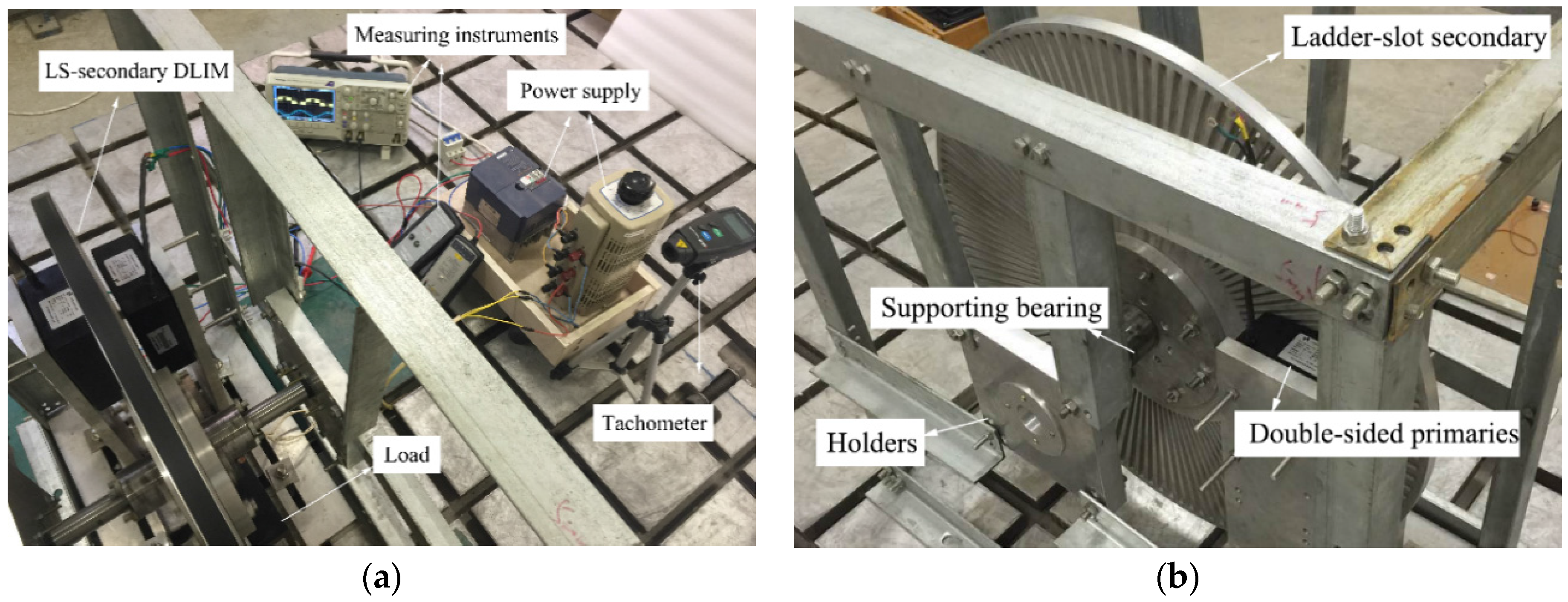
The structure of the platform is shown in Figure 6. Due to the space limitations, the LS-secondary was configured as an aluminum plate with a diameter of 0.74 m. The secondary motion can be considered to be a translational motion because it has a relatively larger diameter than the primary pole pitch.
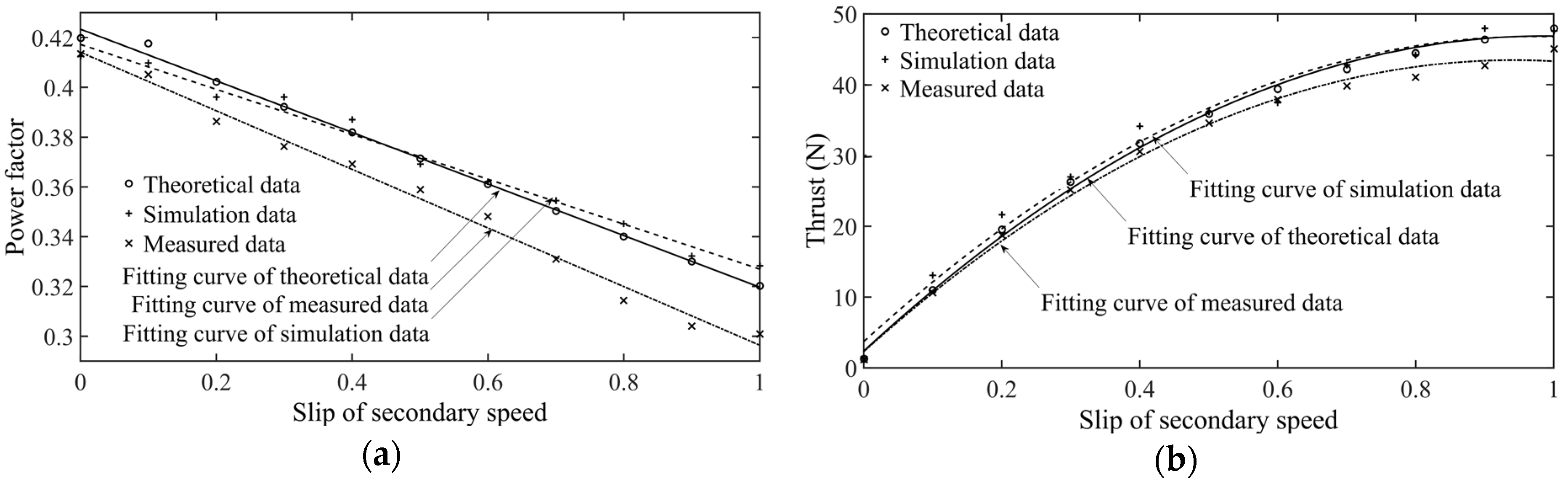
The characteristics of the LS-secondary DLIM are plotted in Figure 7, in which the theoretical, simulated and measured data are compared via fitting curves related to the slip of secondary speed.
The relative error between the theoretical and the simulated results was less than 3.7%, which indicates that the results of the numerical analysis based on the equivalent circuit are consistent with the FEM results. For the most part, the relative error between the theoretical and measured ones was less than 10%, except for the power factor when the secondary slip approached 0.9. The measured power factor and measured thrust were relatively smaller than the theoretical data in general, which is much more clearly revealed via linear regression analysis in Figure 8, with 95% confidence intervals. Functions of linear regression analysis have been presented alongside the figure and the prediction interval. The statistics are listed in Table 2.
Coefficients in the curves related to the theoretical and measured data implies that the data measured during the experiment were slightly smaller than the theoretical data. This tendency correlates with the slots arranged along the radius. Although the diameter of the secondary plate was large enough to consider secondary motion to be a translational motion, the width of the slots near the rim were larger than those closer to the interior, which resulted in a slightly enlarged end leakage inductance of the primary. This phenomenon was also observed in the equivalent circuit of the LS-secondary DLIM.
In the quantile table for F-test, F-test statistics for both the power factor and thrust are larger than F0.95(1,9) = 5.12, which proves that regression functions in Figure 8 are sufficient.
The EM shear stress was also validated via simulation and experimentations, shown in Figure 9. On one hand, based on Equation (8), the simulated data were calculated via 2D field analysis. Since the 2D simulation omits the transverse end of the secondary, the flux density in the air gap is larger than its theoretical value, ultimately leading to larger EM shear stress with a maximum relative error of 8.21%. On the other hand, the measured EM shear stress was calculated via Equation (11). Due to radial ladders on the platform secondary, the area where the EM thrust works is larger than the same LS-secondary with straight ladders. Thus, the EM shear stress becomes smaller than the theoretical counterpart, with a maximum relative error of 12%. Considering the above reasonable factors for error, the numerical calculation of EM shear stress can prove to be accurate enough to estimate whether the LS-secondary DLIM fits the permitted cooling condition listed in [17].
Based on the fitting curves, the maximum value of structural parameters were calculated as σmax = 9.24 kPa, τmax = 4.28 kPa, and kmax = 3.57 × 10⁻⁶ mm, much lower than the practical standard of aluminum ladders.
Therefore, the results of the numerical analysis based on an equivalent circuit have been shown to be both in good agreement theoretically with those of both the simulation and experiment, and effective in practice. The numerical analysis of the VPP EM propulsion method has also been shown to be effective and accurate because it was based on the equivalent circuit model of each section.
5. Conclusions
In this paper, we presented a numerical analysis of variable pole pitch (VPP) electromagnetic (EM) propulsion with ladder-slot-secondary double-sided linear induction motors (LS-secondary DLIMs). The equivalent circuit of the LS-secondary DLIM, in which we considered the longitudinal end effect via a modified Duncan’s model, provided the theoretical foundation of our proposal. To avoid possible disadvantages caused by the slot combination when the LS-secondary encounters various primary pole pitches, principles to arrange the VPP DLIMs were devised. Then, a kinetic analysis of the VPP EM propulsion system based on the design and numerical analysis of each section was conducted to investigate the impacts on the kinetic characteristics of the propulsion system. The foundation of this overall theoretical equivalent circuit for the LS-secondary DLIM was validated via both finite element method (FEM) and experiment. As a result, the numerical analysis method of the VPP EM propulsion system with this type of machine was found to be effective and accurate. Consequently, by combining LS-secondary DLIMs with a VPP EM propulsion scheme, the novel configuration and its numerical analysis proposed in this paper provides an effective method to improve performance of the EM propulsion system.
Acknowledgments
This work was supported in part by the National Natural Science Foundation of China under Grant No. 51077003, Grant No. 51407005, and the Fundamental Research Funds for the Central Universities under Grant No. 2016YJS143.
Author Contributions
Jun Di and Yu Fan conceived of and prepared the theoretical analysis and experiments. During the research, Yu Fan provided general instructions on the overall process; Jun Di completed the theoretical model, performed the experiments with Yulong Zhu, and analyzed the data with Sijia Liu; and Yajing Liu contributed the equipment, materials and measuring devices. This paper was written by Jun Di under the supervision of Yu Fan.
Conflicts of Interest
The authors declare no conflict of interest.
Appendix A

Table A1.
Parameters of the LS-secondary DLIM appearing in this paper.
| Symbol | Parameter | Symbol | Parameter |
|---|---|---|---|
| Estr | Elastic modulus | b2 | Ladder width |
| Fe | Thrust | cosφ | Power factor |
| I2e | Eddy current in the LS-secondary | d2 | Secondary thickness |
| Im | Modified magnetizing current | f | Supply frequency |
| Im0 | Magnetizing current without longitudinal end effect | k | Cogging ratio |
| Kc2 | Carter’s coefficient | ka | a/τ |
| Kdp1 | Primary winding factor | kb | Permitted deflection |
| L1 | Primary leakage inductance | kmax | Maximum deflection |
| L2 | Secondary length | lδ1 | Primary stack width |
| L21 | Secondary leakage inductance referred to primary | lδ2 | Secondary width |
| Lm | Modified magnetizing inductance | m | Mover mass, including secondary mass and loading mass |
| Lm0 | Magnetizing inductance without end effect compensation | m1 | Number of supply phases |
| N | Number of ladders | n | Total number of sections in the VPP EM propulsion |
| Ql1 | The lth ladder’s left edge on normalized time scale | p | Pole-pair number |
| Ql2 | The lth ladder’s right edge on normalized time scale | q | Primary slots per pole per phase |
| R21 | Secondary resistance referred to primary | s | Slip of secondary velocity |
| Rm | Modified magnetizing resistance | s0i | Initial slip in the ith section |
| S | Displacement | v | Secondary speed |
| T | Performance period | w1 | Number of turns per phase |
| Te | EM shear stress | τ | Pole pitch in meters |
| Te,max | Maximum of EM shear stress | τb | Shear strength |
| Vs | Synchronous speed | τmax | Maximum structural shear stress |
| VT | Terminal speed of the EM propulsion | σb | Tensile strength |
| ZLS | Equivalent circuit impedance | σmax | Maximum structural normal stress |
| a | Primary width | ω | Synchronous angular speed |
| b1 | Sum of ladder width and slot width |
Table A2.
Dimensions of the LS-secondary DLIM utilized in the validation.
| Parameter | Unit | Data | Parameter | Unit | Data |
|---|---|---|---|---|---|
| Phase number | - | 3 | Air gap (one side) | mm | 5 |
| Supply voltage | V | 220 | Secondary thickness | mm | 20 |
| Synchronous speed | m/s | 4.5 | Secondary length | mm | 185 |
| Supply frequency | Hz | 50 | Number of ladders | - | 11 |
| Pole-pair number | - | 2 | Ladder width | mm | 11.5 |
| Slots per pole per phase | - | 1 | Slot width | mm | 5.75 |
| Pole pitch | mm | 45 | Tensile strength | MPa | 124 |
| Primary thickness | mm | 65 | Shear strength | MPa | 165 |
| Yoke height | mm | 30.7 | Permitted deflection | mm | 0.575 |
| Tooth height | mm | 39.8 |
References
- Stumberger, G.; Zarko, D.; Aydemir, M.T.; Lipo, T.A. Design and comparison of linear synchronous motor and linear induction motor for electromagnetic aircraft launch system. In Proceedings of the 2003 IEEE International Conference on Electric Machines and Drives (IEMDC’03), Madison, WI, USA, 1–4 June 2003; Volume 1, pp. 494–500. [Google Scholar]
- Hellinger, R.; Mnich, P. Linear Motor-Powered Transportation: History, Present Status, and Future Outlook. Proc. IEEE 2009, 97, 1892–1900. [Google Scholar] [CrossRef]
- Ravanji, M.H.; Nasiri-Gheidari, Z. Design Optimization of a ladder secondary single-sided linear induction motor for improved performance. IEEE Trans. Energy Convers. 2015, 30, 1595–1603. [Google Scholar] [CrossRef]
- Koseki, T.; Sone, S.; Yokoi, T. Investigation of secondary slot pitches of a cage-type linear induction motor. IEEE Trans. Magn. 1993, 29, 2944–2946. [Google Scholar] [CrossRef]
- Mu, S.J.; Chai, J.Y.; Sun, X.D.; Wang, S.M. A variable pole pitch linear induction motor for electromagnetic aircraft launch system. IEEE Trans. Plasma Sci. 2015, 43, 1346–1350. [Google Scholar]
- Mu, S.J.; Chai, J.Y.; Sun, X.D.; Wang, S.M. A novel linear induction motor for electromagnetic aircraft launch system. In Proceedings of the IEEE 2014 17th International Symposium on Electromagnetic Launch Technology (EML), La Jolla, CA, USA, 7–11 July 2014; pp. 1–5. [Google Scholar]
- Zhang, Z.H.; Shi, L.M.; Li, Y.H. Characteristics of double sided linear induction motors with ladder-slit type secondary. Trans. China Electrotech. Soc. 2014, 29, 103–110. [Google Scholar]
- Lee, B.J.; Koo, D.H.; Cho, Y.H. Investigation of linear induction motor according to secondary conductor structure. IEEE Trans. Magn. 2009, 45, 2839–2842. [Google Scholar]
- Yoon, S.B.; Jung, I.S.; Kim, K.C. Analysis and optimal design of the slit type low speed linear induction motor. In Proceedings of the Electric Machines and Drives Conference Record, Milwaukee, WI, USA, 18–21 May 1997; pp. TB2/8.1–TB2/8.3. [Google Scholar]
- Park, S.C. Thrust and attraction force calculation of a linear induction motor with the moving cage-type secondary. In Proceedings of the 2003 Sixth International Conference on Electrical Machines and Systems (ICEMS 2003), Beijing, China, 9–11 November 2003; Volume 1, pp. 226–229. [Google Scholar]
- Park, S.C.; Kim, B.T. Effect of contact resistance between side-bar and secondary conductors in a linear induction motor with a cage-type secondary. IEEE Trans. Magn. 2003, 39, 1562–1565. [Google Scholar] [CrossRef]
- Naugher, L.A.; Baker, N.J.; Atkinson, G. Large air gap squirrel cage induction generator for a tidal turbine. In Proceedings of the 8th IET International Conference on Power Electronics, Machines and Drives (PEMD 2016), Glasgow, UK, 19–21 April 2016; pp. 1–6. [Google Scholar]
- Dalal, A.; Singh, A.K.; Kumar, P. Effect of saturation on equivalent circuit analysis of induction motor in practical scenario. In Proceedings of the 2013 Annual IEEE India Conference (INDICON), Mumbai, India, 13–15 December 2013; pp. 1–5. [Google Scholar]
- Amiri, E. Study of linear induction motor end effects using 3-D FEM and equivalent circuit. In Proceedings of the 39th Annual Conference of the IEEE Industrial Electronics Society (IECON 2013), Vienna, Austria, 10–14 November 2013; pp. 3165–3170. [Google Scholar]
- Duncan, J. Linear induction motor-equivalent-circuit model. IEE Proc. B Electr. Power Appl. 1983, 130, 51–57. [Google Scholar] [CrossRef]
- Fan, Y.; Di, J.; Liu, Y.J. Numerical Analysis of the Double-Sided Linear Induction Motor with a Ladder-Slot Secondary. 2017, in press. [Google Scholar]
- Patterson, D.; Monti, A.; Brice, C.W.; Dougal, R.A.; Pettus, R.O.; Dhulipala, S.; Kovuri, D.C.; Bertoncelli, T. Design and simulation of a permanent-magnet electromagnetic aircraft launcher. IEEE Trans. Ind. Appl. 2005, 41, 566–575. [Google Scholar] [CrossRef]
- Hibbeler, R.C. Analysis of Statically Determinate Structures. In Structural Analysis, 8th ed.; Prentice Hall: Upper Saddle River, NJ, USA, 2012; pp. 33–61. [Google Scholar]
- Shanghai University of Technology, Shanghai Electric. Design of linear induction motors with non-magnetic secondary. In Linear Induction Motor, 1st ed.; China Machine Press: Beijing, China, 1979; pp. 59–79. (In Chinese) [Google Scholar]
Figure 1.
Structure of the ladder-slot (LS)-secondary.
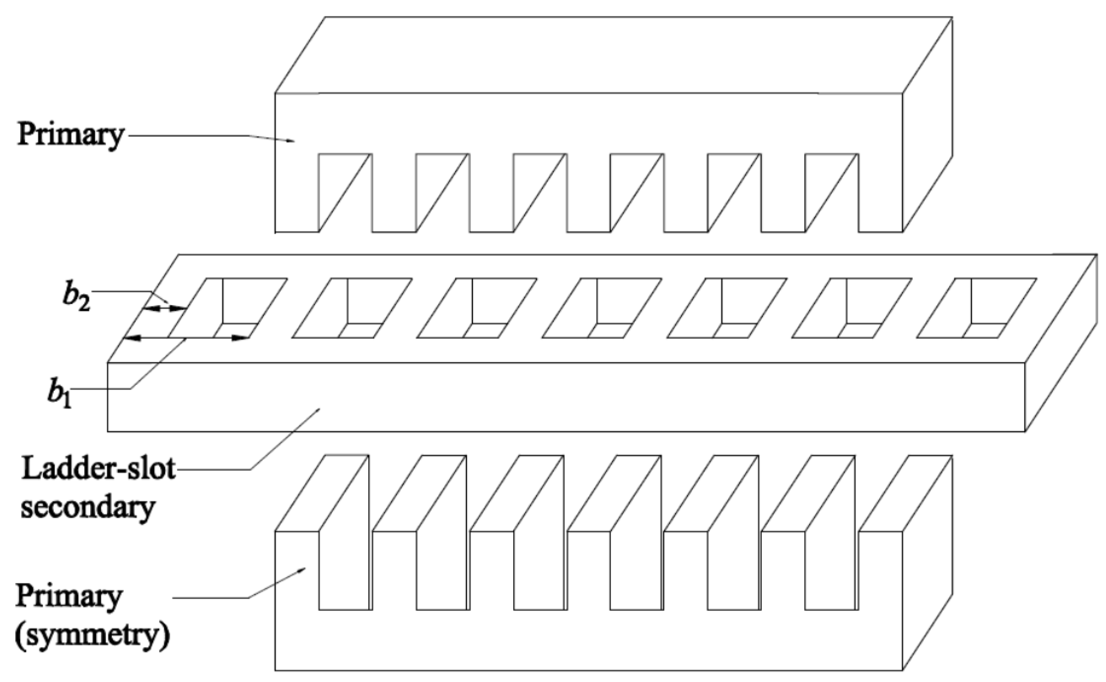
Figure 2.
Modeling of the LS-secondary DLIM: (a) Equivalent circuit of the LS-secondary; (b) Eddy current per unit length in the LS-secondary, combining Duncan’s model with discrete ladders.
Figure 2.
Modeling of the LS-secondary DLIM: (a) Equivalent circuit of the LS-secondary; (b) Eddy current per unit length in the LS-secondary, combining Duncan’s model with discrete ladders.

Figure 3.
Schematic diagram showing the operation of variable pole pitch (VPP) electromagnetic (EM) propulsion.
Figure 3.
Schematic diagram showing the operation of variable pole pitch (VPP) electromagnetic (EM) propulsion.
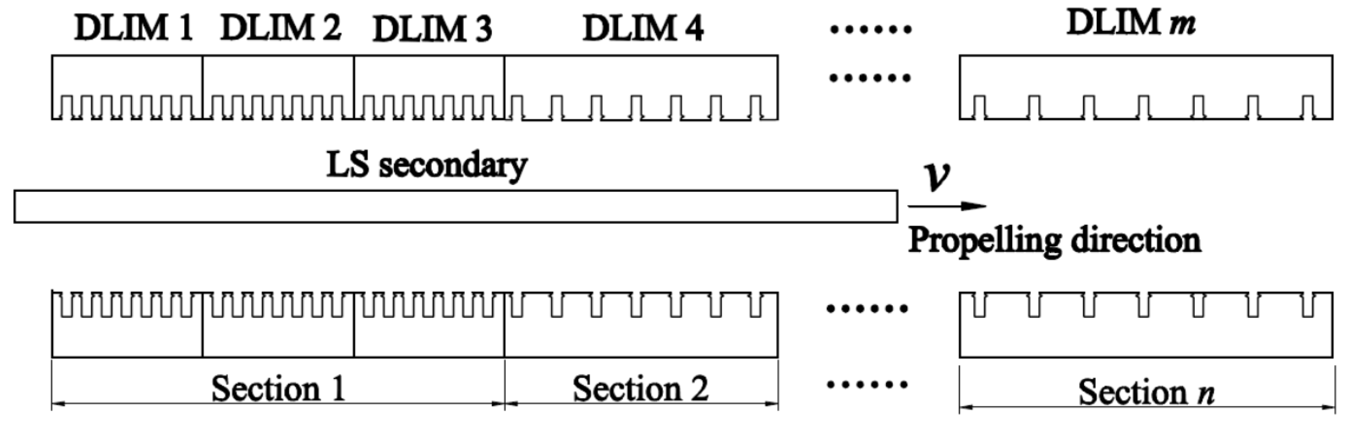
Figure 4.
Design and calculation flowchart of the VPP EM propulsion.

Figure 5.
Field distribution via finite element method (FEM) simulation: (a) Flux density; (b) Secondary eddy current density.
Figure 5.
Field distribution via finite element method (FEM) simulation: (a) Flux density; (b) Secondary eddy current density.

Figure 6.
Structure on the platform: (a) Overall structure for the experiment; (b) LS-secondary DLIM with an aluminum plate.
Figure 6.
Structure on the platform: (a) Overall structure for the experiment; (b) LS-secondary DLIM with an aluminum plate.

Figure 7.
Fitting curves showing the characteristics vs. slip of secondary speed: (a) Power factor; (b) Thrust.
Figure 7.
Fitting curves showing the characteristics vs. slip of secondary speed: (a) Power factor; (b) Thrust.

Figure 8.
Regression results comparing the theoretical, simulated and measured data: (a) Theoretical data of power factor vs. simulation data of power factor; (b) Theoretical data of power factor vs. measured data of power factor; (c) Theoretical data of thrust vs. simulation data of thrust; (d) Theoretical data of thrust vs. measured data of thrust.
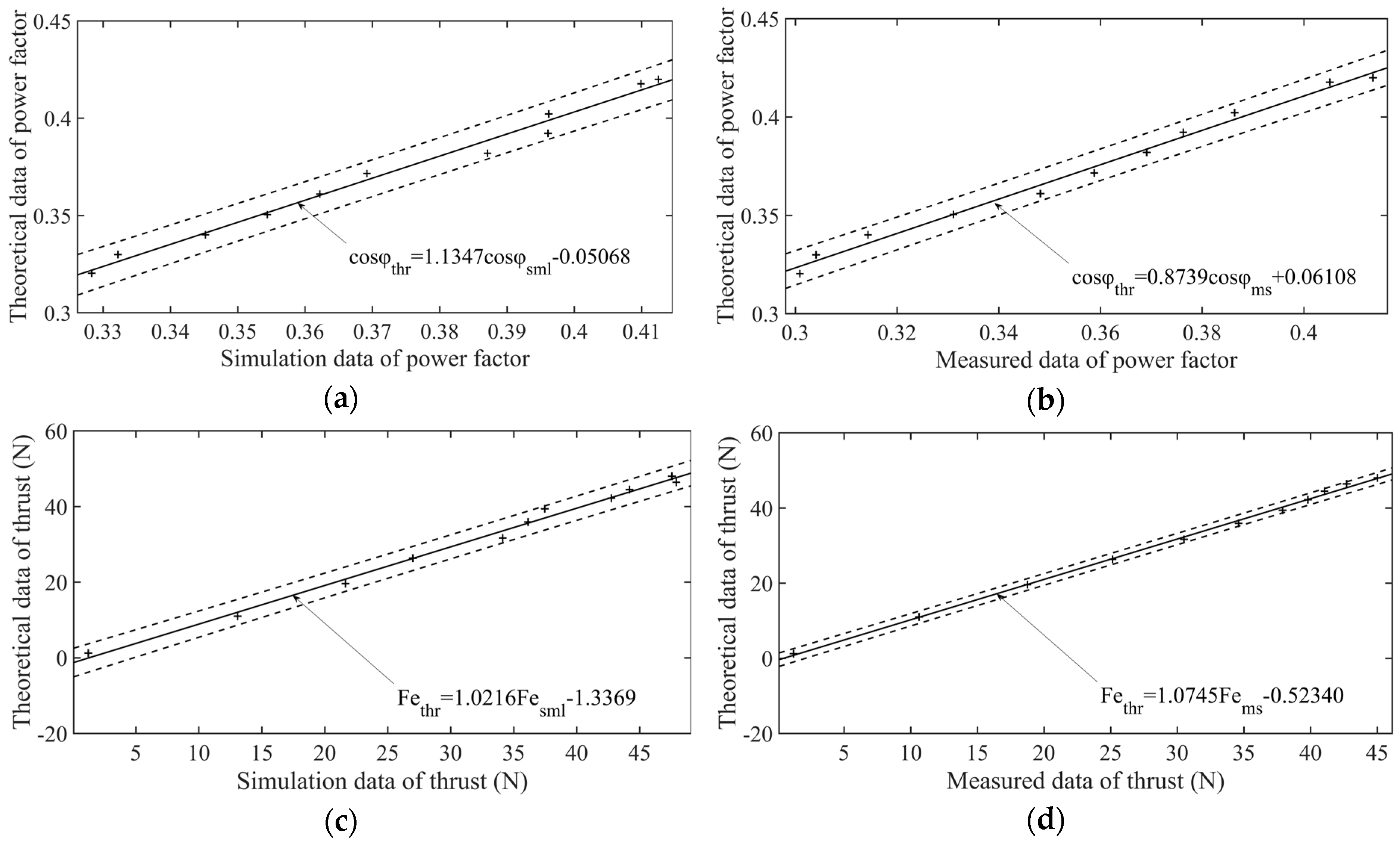
Figure 9.
Fitting curves of EM shear stress vs. slip of secondary speed.
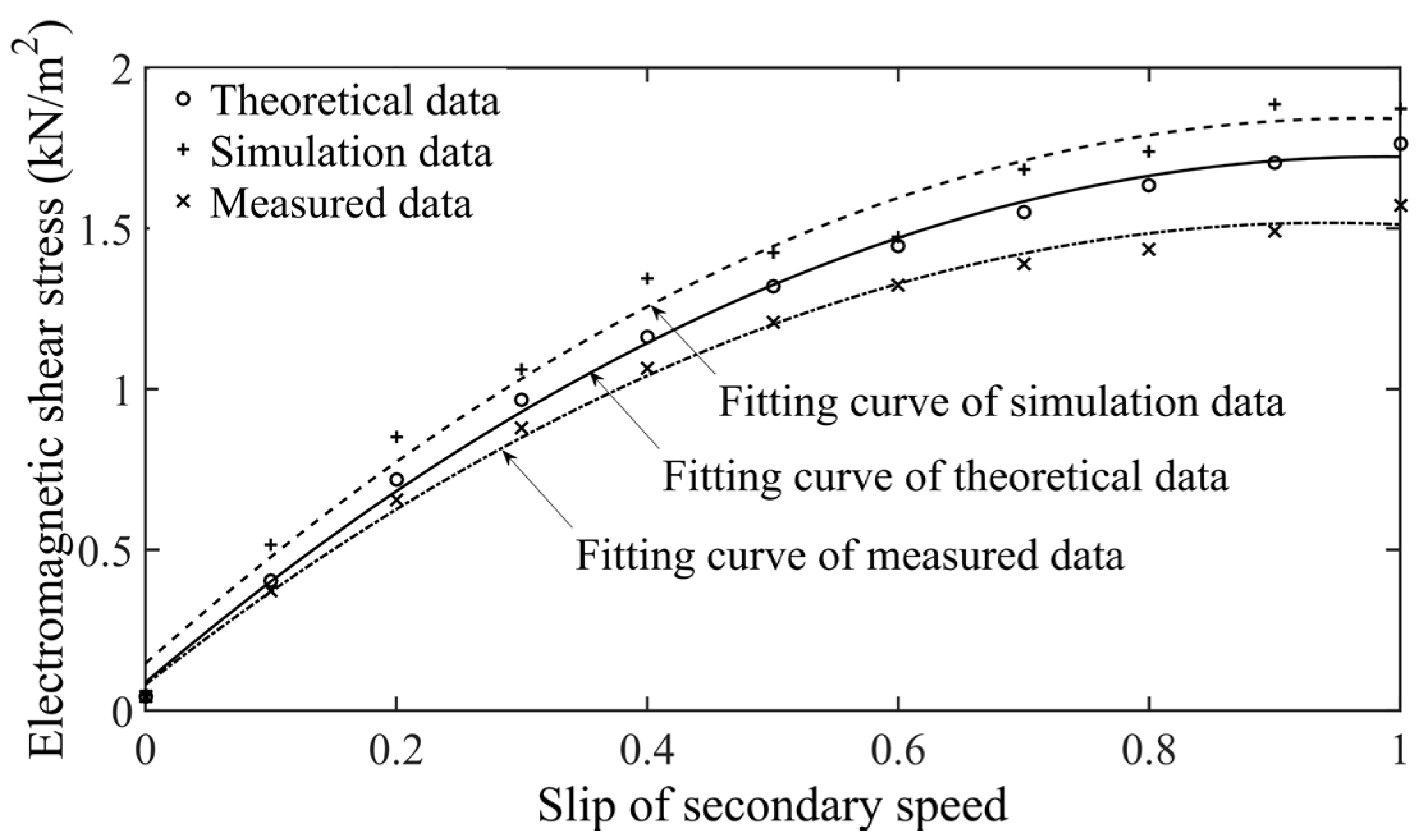
Table 1.
The variable pole pitch (VPP) electromagnetic (EM) propulsions analyzed in this paper.
| Supply Voltage | Category | Section | q | Vs (m/s) | f (Hz) | ka | Displacement (m) | Performance Period (s) | Te,max (kN/m2) |
|---|---|---|---|---|---|---|---|---|---|
| 10 kV | Sections with a constant Vs | 1 | 1 | 340 | 300 | 1.44 | 172.81 | 6.18 | 33.2 |
| 2 | 2 | 340 | 150 | 0.72 | 2254.41 | 17.59 | 17.4 | ||
| 3 | 3 | 340 | 100 | 0.48 | 2979.75 | 11.5.1 | 29.4 | ||
| Sum | - | - | - | - | 5405.97 | 35.28 | - | ||
| Sections with variable Vs | 1 | 1 | 56.7 | 50 | 1.44 | 3.55 | 0.79 | 90.1 | |
| 2 | 2 | 204 | 90 | 0.72 | 577.38 | 9.86 | 57.8 | ||
| 3 | 3 | 340 | 100 | 0.48 | 5052.85 | 24.65 | 29.4 | ||
| Sum | - | - | - | - | 5633.78 | 35.30 | - | ||
| 220 V | Sections with a constant Vs | 1 | 1 | 18.9 | 210 | 1.44 | 4.89 | 2.17 | 6.57 |
| 2 | 2 | 18.9 | 105 | 0.72 | 11.81 | 1.56 | 7.15 | ||
| 3 | 3 | 18.9 | 70 | 0.48 | 54.72 | 3.37 | 6.27 | ||
| Sum | - | - | - | - | 71.42 | 7.10 | - | ||
| Sections with variable Vs | 1 | 1 | 4.5 | 50 | 1.44 | 56.02 | 17.38 | 1.76 | |
| 2 | 2 | 10.8 | 60 | 0.72 | 54.01 | 6.15 | 3.11 | ||
| 3 | 3 | 18.9 | 70 | 0.48 | 54.72 | 3.37 | 6.27 | ||
| Sum | - | - | - | - | 164.76 | 26.89 | - |
Table 2.
Linear regression statistics in Figure 7.
Table 2.
Linear regression statistics in Figure 7.
| Characteristics | Figure | Significance Level | Correlation Coefficient | F-Test Statistic | F-Test Probability | Error Variance |
|---|---|---|---|---|---|---|
| Power factor | 7a | 0.05 | 0.9878 | 730.23 | 6.3029 × 10⁻¹⁰ | 1.6038 × 10⁻⁵ |
| Power factor | 7b | 0.05 | 0.9122 | 1015.9 | 1.4469 × 10⁻¹⁰ | 1.1568 × 10⁻⁵ |
| Thrust | 7c | 0.05 | 0.9931 | 1298.5 | 4.8314 × 10⁻¹¹ | 1.8070 |
| Thrust | 7d | 0.05 | 0.9984 | 5701.4 | 6.3408 × 10⁻¹⁴ | 0.4138 |
© 2017 by the authors. Licensee MDPI, Basel, Switzerland. This article is an open access article distributed under the terms and conditions of the Creative Commons Attribution (CC BY) license (http://creativecommons.org/licenses/by/4.0/).
Share and Cite
MDPI and ACS Style
Di, J.; Fan, Y.; Liu, Y.; Liu, S.; Zhu, Y. Variable Pole Pitch Electromagnetic Propulsion with Ladder-Slot-Secondary Double-Sided Linear Induction Motors. Appl. Sci. 2017, 7, 481. https://doi.org/10.3390/app7050481
AMA Style
Di J, Fan Y, Liu Y, Liu S, Zhu Y. Variable Pole Pitch Electromagnetic Propulsion with Ladder-Slot-Secondary Double-Sided Linear Induction Motors. Applied Sciences. 2017; 7(5):481. https://doi.org/10.3390/app7050481
Chicago/Turabian StyleDi, Jun, Yu Fan, Yajing Liu, Sijia Liu, and Yulong Zhu. 2017. "Variable Pole Pitch Electromagnetic Propulsion with Ladder-Slot-Secondary Double-Sided Linear Induction Motors" Applied Sciences 7, no. 5: 481. https://doi.org/10.3390/app7050481
Note that from the first issue of 2016, this journal uses article numbers instead of page numbers. See further details here.