Multi-Party Optimal Operation for Distribution Networks Containing DC-Linked Microgrids: Integrated Network Reconfigurations and Energy Sharing


State Key Laboratory of Alternate Electrical Power System with Renewable Energy Sources, North China Electric Power University, Beijing 102206, China
*
Author to whom correspondence should be addressed.
Appl. Sci. 2017, 7(11), 1194; https://doi.org/10.3390/app7111194
Submission received: 14 October 2017
/
Revised: 10 November 2017
/
Accepted: 16 November 2017
/
Published: 20 November 2017
(This article belongs to the Section Energy Science and Technology)
Abstract
:With the development of Microgrids (MG) in distribution networks, how to coordinate the reconfiguration of distribution networks with the energy sharing of Direct Current (DC)-linked multi-MG is an unsolved problem. In this paper, a multi-party optimization framework is proposed, the involving parties include the Distribution Network Operator (DNO), the Multi-MG Coalition Operator (MCO), and the MG operator. For the DC-linked MGs, the MCO is obligated to coordinate the energy sharing, a stochastic optimal scheduling model for the MG coalition is formulated, considering the uncertainties of Photovoltaic (PV), Wind Turbines (WT), and load power. Moreover, a billing mechanism is designed to distribute the cost of each MG participated in the energy sharing. For the distribution network, an event triggered dynamic reconfiguration model is proposed. Based on the scheduling results of MCO, the decisions of switch operations are finally co-decided by the expected exchanging power of the MGs and the real-time errors caused by uncertainty factors. Finally, a modified IEEE-33 nodes distribution system are used to test and verify the effectiveness of the method.

1. Introduction
With the increasing penetration of renewable energy resources (RES) in distribution networks, how to utilize the random and volatile power has become a critical part of emerging smart grid designs [1]. In order to eliminate the negative impact of RES, the microgrid (MG) is considered to be a possible solution. Generally, the MG can be regarded as an integrated system with distributed energy resources (DERs) and loads, which can be operated both on grid-tied and isolated mode [2,3]. With the increasing of MGs in community level, the interconnected multi-MG has shown greater advantages on lower the operation cost and enhance the reliability [4], by coordinated energy sharing [5,6] and provision of urgent supply [7].
Until recently, a new type of direct current (DC)-link based on voltage source convertor (VSC) is proposed. DC-linkage is preferred over existing alternating current (AC)-linkage for the following two aspects. In isolated mode, DC-linked MGs can operate at different voltages and frequencies, if necessary, backup active power in an underloaded MG can be transferred to an overloaded MG to improve the supply reliability of the whole network [7]. Such DC-link can then be turned off to reduce its operating losses when both MGs do not need additional generation or do not have extra generating capacities for sharing [8]. In grid-connected mode, DC-link equipped at the end feeder, which is also named soft open points (SOP), improves the power handling capacity, voltage profile of AC distribution feeder and reduces the power loss [9,10]. Furthermore, it can achieve rapid recovery of non-fault areas in the case of failure, and thus improve the reliability of the whole network [11]. Therefore, the DC-links can be deployed by the MG’s owners between the adjacent MGs in community level, and then the energy trading within the multi-MG can be mutually decided by themselves, without paying network tariffs to the Distribution Network Operator (DNO). In this regard, the cooperative DC-linked multi-MG would change the power flows of the distribution system, and then make the reconfiguration decisions of distribution network less efficient, which is generally operated by DNO to minimize the power losses. Consequently, how to integrate the reconfiguration model with optimal operations of DC-linked MGs is an essential problem to be addressed.
Many efforts have been devoted to solving the optimal operations of multi-MG, which can be roughly classified into two types by the operation goals: (1) reduce their operation cost (or increase the operation profit); (2) improve the system reliability. For the first type, the operation goal is generally set as minimize the overall operation cost of multi-MG [12,13,14]. The involving DERs may include diesel generations, microturbines, Photovoltaic (PV) panels, Wind Turbines (WT), and battery energy storages. Considering that the participated MGs may have different types of DERs, the operation cost could be reduced by maximizing the renewable energy sharing. During the operation, centralized or distributed optimization algorithms can be used, according to the different scenarios [15,16]. The second type of multi-MG operation can be activated when the utility grid is outage (i.e., power system faults, unexpected disaster events, etc.). In this scenario, the operation goal could be maximize the load restore ability for important end users. The operation frameworks can be concluded as the hierarchical structure (i.e., DNO and MG operators) [17] and horizontal structure (i.e., only MG operators) [18]. In aforementioned studies, if the multi-MG is isolated from the utility grid, they only need to consider the energy trading between them. Otherwise, if the multi-MG is grid-connected, they still need to trade the energy with the AC distribution network. However, the conditions are changed with the introducing of DC-linked MGs in distribution networks: (i) the MG operators use the private DC-links as the first priority for energy sharing; (ii) they exchange the energy with the distribution network only when the aggregated energy is surplus or deficient.
Meanwhile, the reconfiguration of distribution network is a traditional operation problem, which is a process of shifting the state of sectionalizing switches and tie switches to achieve the goal such as minimizing the network loss [19,20], improving the reliability [21], maximizing the renewable energy penetration [22,23], and relieving overload in the network [24,25]. In the distribution network with a number of DC-linked MGs, the traditional reconfiguration framework may not be used, due to the uncontrolled impact from the private energy trading between MGs. As the MGs are operated by independent entities, they can actively change the scheduling and trading scheme, and finally lead to uncontrolled impact on the distribution network. In this regard, the reconfiguration decisions would be more difficult, which are required to be coordinated with the scheduling of DC-linked MGs.
As several entities are involved in the operation, the optimization problem should be implemented by multiply parties with different time scales. From the viewpoint of DNO, reconfiguration of distribution network could be a possible way to reduce the network power losses. However, with the connection of DC-linked MGs, the reconfiguration results could be seriously influenced by the dynamical changes of private energy trading and uncertainties of RES. From the viewpoint of MG owners, as the network tariff can be ignored, it is more economic for the MGs to work as a coalition via DC-links. In this regard, it is important to achieve the optimal operation and fair cost allocation for the coalition, which can be seen as a local market in the community level [26,27].
To this end, in order to solve the aforementioned problems, this paper proposes a cooperative operation method for distribution networks with DC-linked MGs, which has integrated the reconfiguration problem of distribution network and the optimal scheduling problem of multi-MG in a unified framework. As the two parts are operated by different parties with hybrid time scales, this is a new problem which has not been addressed in the literature of smart grid, to the best of our knowledge. The detailed contributions are listed as follows.
- (1)
- A multi-party optimization framework is designed, which includes the reconfiguration of the distribution network and scheduling of the DC-linked MGs.
- (2)
- For the DC-linked MGs, a stochastic optimal scheduling model for the coalition is formulated, considering the uncertainties of PV, WT, and load power. Moreover, a billing mechanism is designed to distribute the cost the coalitional operations.
- (3)
- For the distribution network, an event triggered dynamic reconfiguration model is proposed. The decisions of switch operations are finally co-decided by the expected exchanging power of the MGs and the real-time errors caused by uncertainty factors.
2. Framework
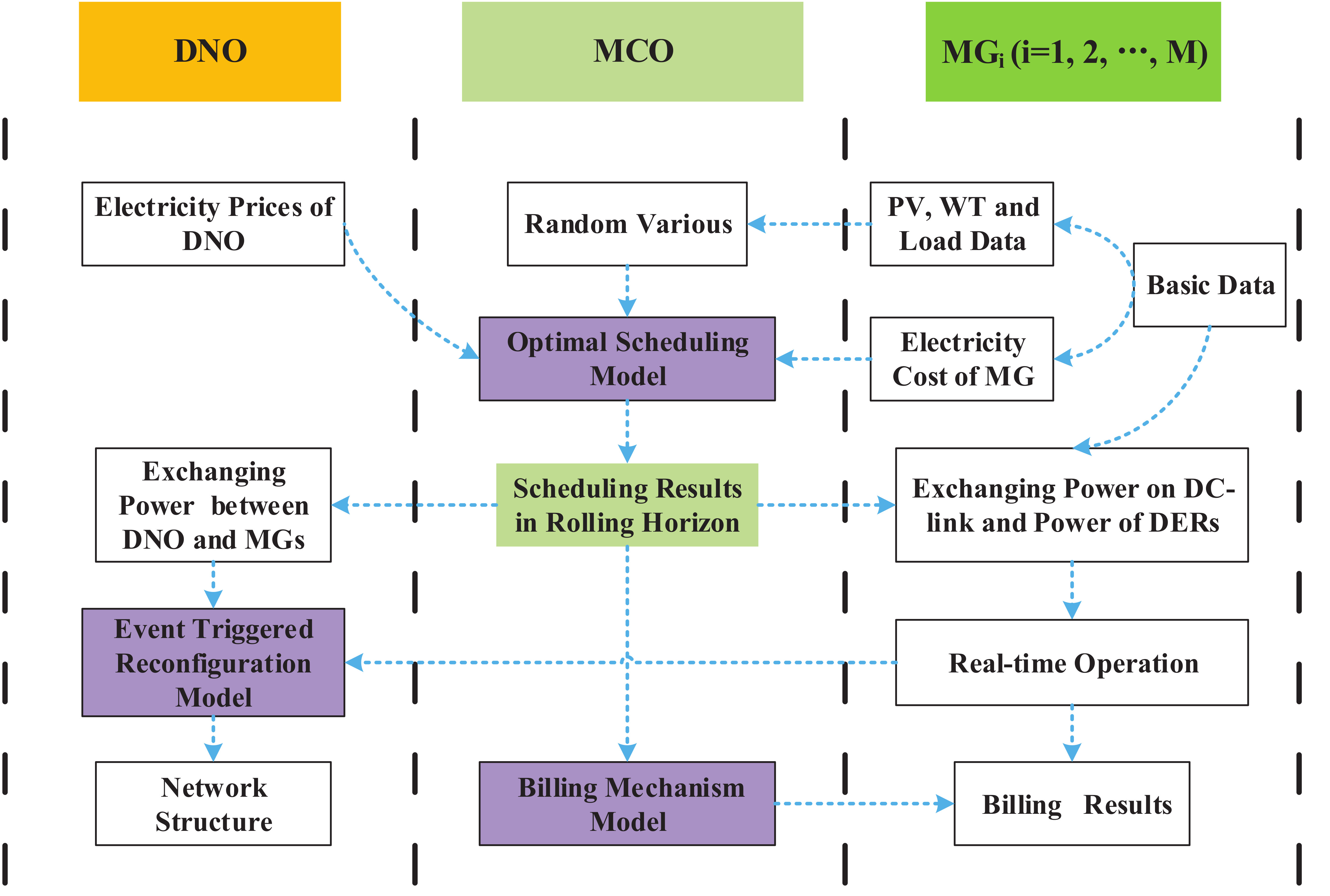
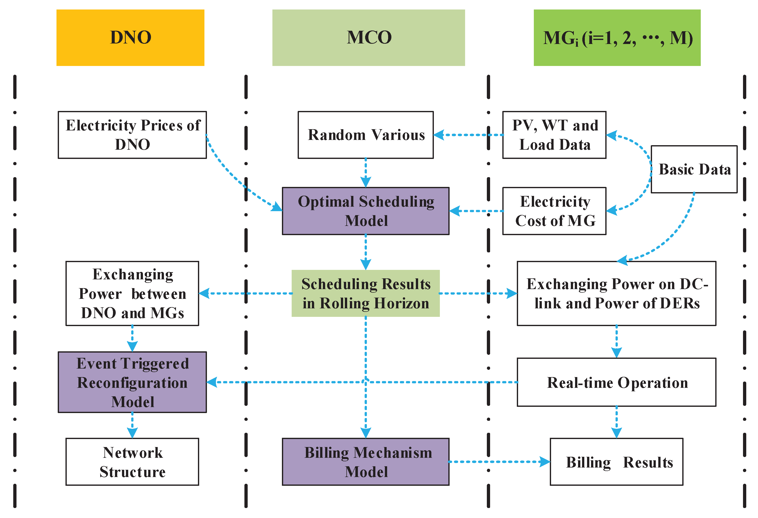
In the framework, there are three entities involved. First, the DNO, it is responsible to make the decisions of distribution network reconfigurations, aims to keeping the network power loss within a low level. Second, the MG operators, they are responsible for controlling their own DERs, and providing electricity services to the end customers. Third, a new entity, namely as Multi-MG Coalition Operator (MCO), who is responsible to act as a bridge between DNO and MG operators.
The interactions among DNO, MCO, and MG operators are shown in Figure 1. Briefly, the overall process can be classified into three different stages: (i) The MCO collects basic information from the MG operators and price information (i.e., importing and exporting energy prices between DNO and MGs) from the DNO, and makes optimal scheduling in a rolling horizon manner for all the controllable DERs in the coalition, considering the uncertainties of PV, wind and load power; (ii) After receiving the expected exchange power and real-time exchange power between MGs and distribution network, the DNO decides the reconfiguration scheme using an event triggered dynamic reconfiguration model; (iii) After each day’s operation, the MCO distributes the operation cost based on the billing mechanism and metering data.
3. Stochastic Scheduling Model of DC-Linked MGs
3.1. Basic Model
Load, RES and synchronous generator are typically integrated to constitute a MG. Generally, there are stochastic errors in the day-ahead prediction values of load demand and RES.
3.1.1. Load
Load can be denoted as a form of forecasted value and errors
where is the actual value of load demand at time t, is the predicted value of load demand at time t, is the prediction error at time t which obeys normal distribution with the mead of 0 and standard deviation of [28].
3.1.2. RES
In the MG, the RES is uncontrolled DERs, which should be consumed as much as possible. Considering the forecasting errors, the power of PV and WT generations can be denoted as follows:
where , and are the actual value, predicted value, and prediction error of PV at time t, respectively; , and are the actual value, predicted value and prediction error of WT at time t, respectively. Generally, the prediction errors can be assumed that obey normal distributions with the mead of 0 and standard deviation of and [29].
3.1.3. Synchronous Generator
Synchronous generators are controlled DERs in the MG, i.e., diesel generator, microturbine, etc. Generally, the operation cost can be defined as:
where is the operation cost of the synchronous generator at time t; is the output power of synchronous generator at time t; a, b, c are the cost coefficients [30].
3.2. Objective Function
The objective function of scheduling cost of DC-linked multi-MGs is formulated as:
where is the unit generation cost of RES; and are the prices of purchasing electricity from DNO and selling to DNO, respectively; is the exchanging power between MG and DNO at time t (positive for purchasing and negative for selling); T is the scheduling time horizon; V, W, G and M are the numbers of PVs, WTs, synchronous generators and MGs, respectively.
In order to deal with the uncertainties, the output powers of PV, WT and load demand are modeled as random variables , and . In stochastic programming, , and are denoted using a finite set of scenarios . Each scenario consists of a vector of PV, WT, and load:
where , and are the power values of PV, WT and load in scenario at time t, respectively.
Each scenario has a probability of occurrence , in such a way that the sum of the probabilities over all scenarios is equal to 1, i.e., .
Using the stochastic programming, the objective function can be reformulated by adding random variables and conditional value-at-risk ():
where is the expected cost of scheduling, and the is multiply a risk coefficient . Due to the cost of the scheduling is related to the value of , the system operator can make reasonable operating scheduling decision according to the risk preference degree.
where is an auxiliary variable; is the confidence level.
3.3. Constraints
3.3.1. Power Balance
At any time, the power generation and consumption, as well as the exchanging power with distributed network in scenario should be balanced:
3.3.2. Power Constraints of Generators
The output of synchronous generators and RESs have their own feasible range:
where , and , are the highest and lowest output of PV and WT, respectively; the output of synchronous generator ranges from to ; is the reserve capacity.
3.3.3. Exchanging Power Constraints
Considering the power line capacity , the exchanging power between MGs and DNO is limited by
Considering the capacities of DC-line and converters, the exchanging power on DC-link is limited by
where is the maximum DC power.
3.3.4. Constraints
constraint is used to measure risk of scheduling cost caused by the uncertainties such as the prediction errors of RESs and load demands. constraints can be transformed into the following expression
3.4. Solution
Based on the distribution of random variables, we can generate a vector of random various including PV, WT and load demand in scenario as the input data. Decision variables for Function (7) include:
4. Dynamic Reconfiguration of Distribution Network
4.1. Power Loss Model
The reconfiguration of distribution network is a traditional operation problem, which is a process of shifting the state of sectionalizing switches and tie switches to minimize the power losses. Power flows in a distribution network are computed by the following equations and the related topology are shown in the blue dashed box of Figure 2.
where and are the injection active and reactive power of upstream branch of node i; is the set of subnode of node i; and are the active power and reactive power of load of node i, respectively; , and are the unit resistance, unit reactance and length of branch j, respectively.
Thus, the power loss at time t can be expressed as follows
where N is the total number of branches.
4.2. Power Loss Model Considering the DC-Linked MGs
As shown in Figure 2, DC-link placed between two MGs can serve as additional sources of active and reactive powers. Active power is transferred from an exporting MG to an importing MG to serve as an extra generator [7]. In order to control the exchanging energy, the voltage regulation method can be applied to control the active and reactive power of the AC-DC-AC convertor [9]. Therefore, DC-link within a MG coalition does not have impact on the open loop operation of distribution network, and the MGs can be equivalent to a PQ node with constant power factor in the power flow calculation.
Thus, the power flow of the distribution network containing DC-linked MGs can be reformulated as follows.
where and is the active and reactive power exchanging between MGs and DNO, respectively.
Thus, the power loss at time t is:
4.3. Event Triggered Dynamic Reconfiguration Model
Aiming at minimizing the power losses of a certain time period in the future, the reconfiguration problem is to decide the open or close status of every switch, which finally change the topologies of a distribution network. Thus, the dynamic reconfiguration model can be represented as:
where is time horizon for calculating power losses, is the selected topology of a distribution network for time period , is the set of total possible topologies of the distribution network.
Generally, it can be assumed that each branch is equipped with a switch, thus a topology can be further defined as the status of switches in the distribution networks.
where is the status of the i-th switch, i.e., 1 for close, 0 for open.
In order to cooperate with the scheduling of the MG coalition, the DNO can make decisions after receiving the expected exchanging energy . However, due to the forecasting errors, the errors of expected exchanging energy are also cannot be omitted, even with the utilization of stochastic programming. Finally, the errors may influence the efficiency of reconfiguration model. Thus, the power flow of the distribution network containing DC-linked MGs can be updated as follows.
where and is the exchanging power deviation of active and reactive power exchanging between MGs and DNO, respectively.
As a result, the actual power loss at time t is:
Furthermore, considering the real-time errors, the dynamic reconfiguration model can be updated as follows:
By solving (29) at time t, is the optimal decided topology of a distribution network for time period . However, with the time progress, may not be the optimal solution for time period due to the real-time operation errors at time . Extremely, if the DNO choose to update the reconfiguration scheme every time slot, the switches could be operated very frequently to change the network topologies, which is also not economical considering the cost of switch operations. To address this problem, a event triggered model is formulated as follows.
where is the current topology of distribution network, is the unit cost of changing switches, and is the total number of switches changed; is the unit cost of power loss.
At time t, if , that means the current topology is already the optimal solution, which don’t need to make any change; otherwise, if , the current topology is not the optimal solution, the DNO should compare the benefit with the cost caused by switch operations, as expressed in (30). Thus, the DNO can finally achieve a trade-off between optimal solutions and complicated switch operations.
4.4. Constraints
4.4.1. Voltage Constraints
The inequality constraint on voltage of each node is
where , is the upper limit and lower limit of node voltage.
4.4.2. Branch Power Limit
The power limit of branch can be described as
where is the maximum power of branch j when the distribution network operates normally.
4.4.3. Network Structure Constraints
According to the operation requirements of media voltage distribution networks, the topology must be open loop. In the reconfiguration, this requirement should be guaranteed, which is described as follows.
4.5. Solution Algorithm
The dynamic reconfiguration of distribution network is a complex non-convex, mixed-integer programming and typical non-linear problem, which appropriately involves the use of the evolutionary algorithms such as genetic algorithm (GA). Figure 3 shows the flowchart of reconfiguration model. To preserve the radial structure of the network, each loop can only have one switch open at a time. Thus, a gene in the chromosome represents the ID of opened switch in a loop. Based on the total number of loops in the network, the decimal coding is used to represent the chromosome by sequencing the opened switches of all the loops [30].
5. Billing Mechanism
Multi-MG combines as a cooperative coalition via DC-link to make a deal with DNO in order to minimize the scheduling cost. After everyday’s operation, the coalition needs a suitable and fair mechanism to distribute the total operation cost. Generally, each MG has its own DERs and loads, and the unit energy costs of its DERs are different. Basically, the principle is that each MG provides the own customers with the low cost DERs. That is, we should sort the DERs from the low cost to the high cost. Let DERs in a MG indexed as , respectively, and to simplify the problem explanation, we omit t for the following equations (i.e., C denotes , P denotes etc.).
Firstly, the cost of DERs in a MG can be denoted as a cost set C:
where is the generation cost of DERs.
The output energy of DERs in the MG can be denoted as a energy set P:
where is the output energy of DERs.
After sorting from low to high, the cost of DERs are updated as follows:
And the corresponding energy set can be updated as well:
Moreover, the cost trading between two MGs can be expressed as:
where is the cost of power consumed by MG’s own load.
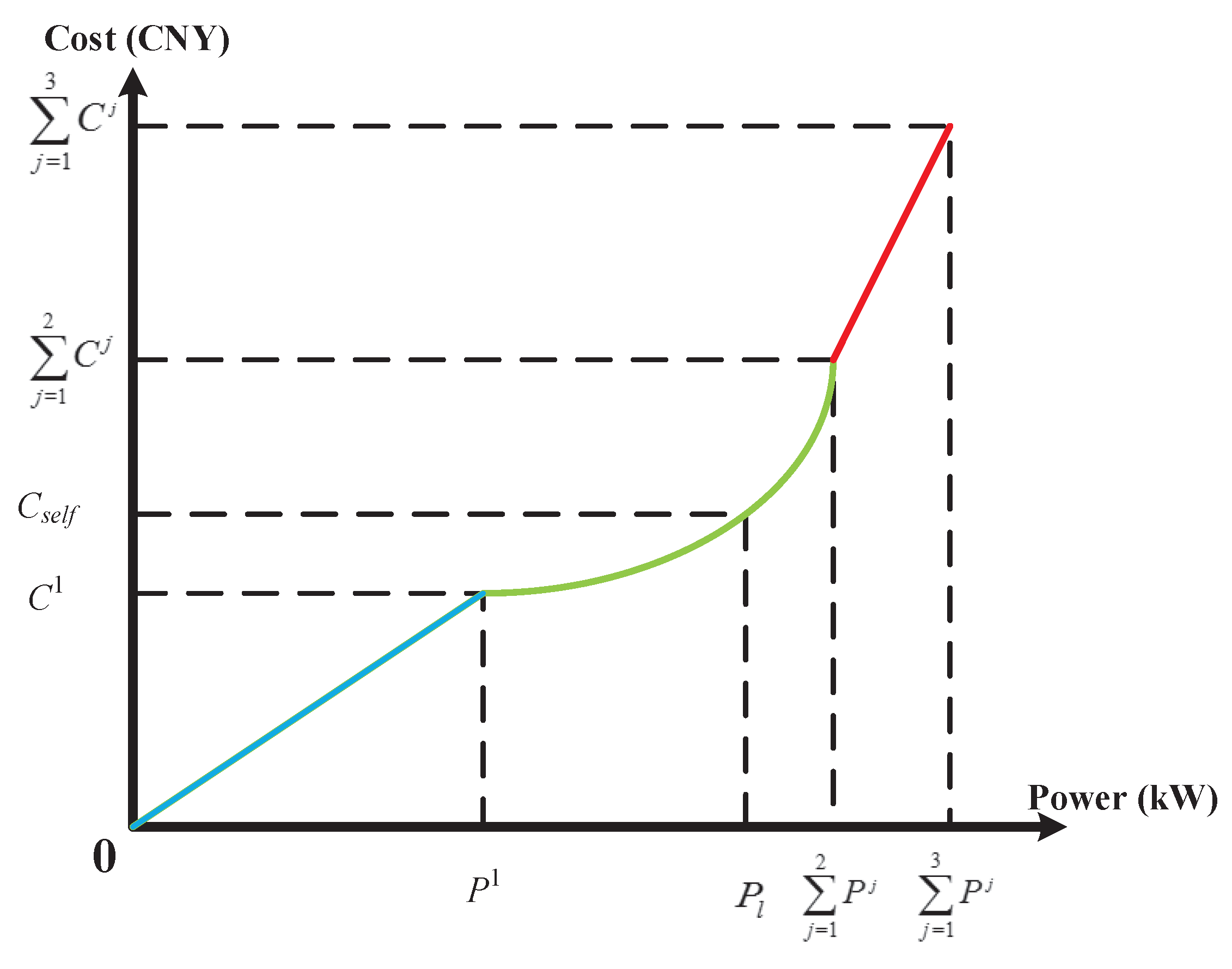
According to the principle that the low cost DERs should meet the load demand of local customers in each MG, can be defined as a piecewise function:
Take 2 MGs named and as an example, the cost function of can be seen in Figure 4. It is assumed that there are three types of DERs within . The unit energy costs of its DERs combined as a cost set named , the corresponding power set is . After sorting from low to high, the cost and power set of DERs are updated as follows: , . is the power generated by PV and WT, and is the power generated by microturbine, and the MG exchanges power of with DNO.Therefore, the cost which ought to pay can be expressed as follows:
As can be seen from Figure 4, can be denoted by
6. Case Study
The IEEE 33-bus test system [32] is used to validate the performance of the proposed method (as shown in Figure 5). The test system is composed of 32 branch lines and 5 tie lines, and each line has a switch as well. The system voltage is 12.66 kV, the maximum capacity is 10 MVA, and the maximum load is kVA. In order to fit the testing of the proposed method, three MGs, named as , and , are respectively connected to node 15, 31 and 28, which are tied by two separated DC-links. In the three MGs, the DERs include microturbines, PVs and WTs, which provide electricity services for residential, industrial and commercial users.
The capacity of DERs are shown in Table 1 and the power limit on DC-link converters are set as 200 kVA. The parameters of the GA are: , , generation = 20, population = 50. As shown in Figure 6, 24 h of actual data of PV, WT and load in a day are collected to test the method. For the sake of tractability, the original scenario set is adequately trimmed down to 5 scenarios via scenario-reduction techniques [33].
6.1. Results of Stochastic Scheduling
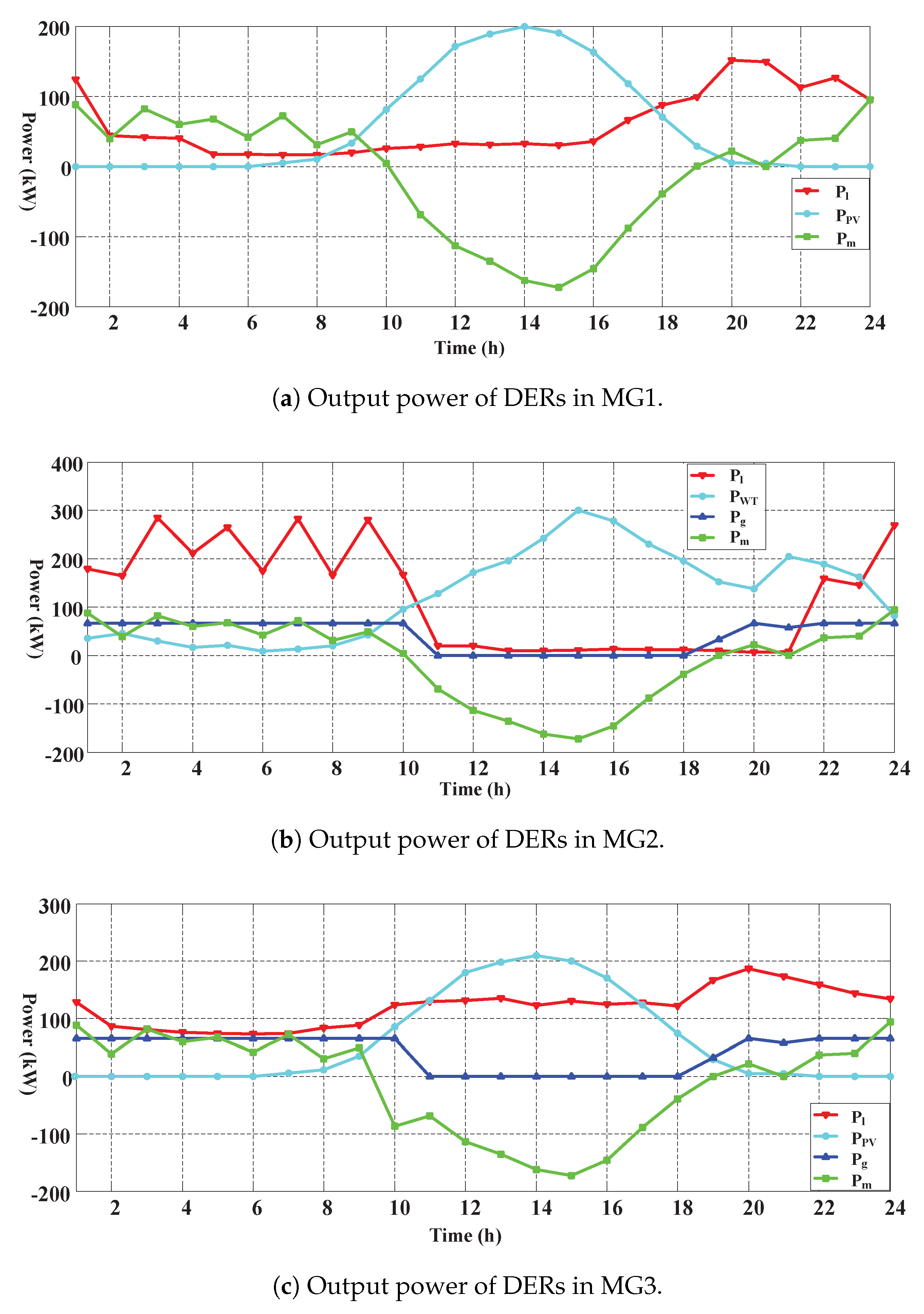
Results of a stochastic scheduling of 3 MGs are shown in Figure 6. Within the coalition, each MG has an equivalent position regardless of its own load demand and DERs’ output. The exporting and importing power are exchanged via DC-links.
In Figure 6, the scheduling results can be divided into three time periods. Firstly, in the early morning, the RES is insufficient, the MCO has to purchase electricity from the DNO at a higher price and maximize the output of microturbines to meet its load demand. There is an industrial shock load in which causes the fluctuating electricity purchasing from the DNO from 2:00 to 10:00. Secondly, from 11:00 to 19:00, with the increasing solar and wind energy, the MCO sells its extra electricity to DNO and even turns off the microturbines to minimize the operation cost. Finally, from 20:00 to 24:00, the amount of purchasing electricity from the DNO has been gradually increased, and the microturbines have been operated at the rated power, due to the reduction of RES and increased load demand.
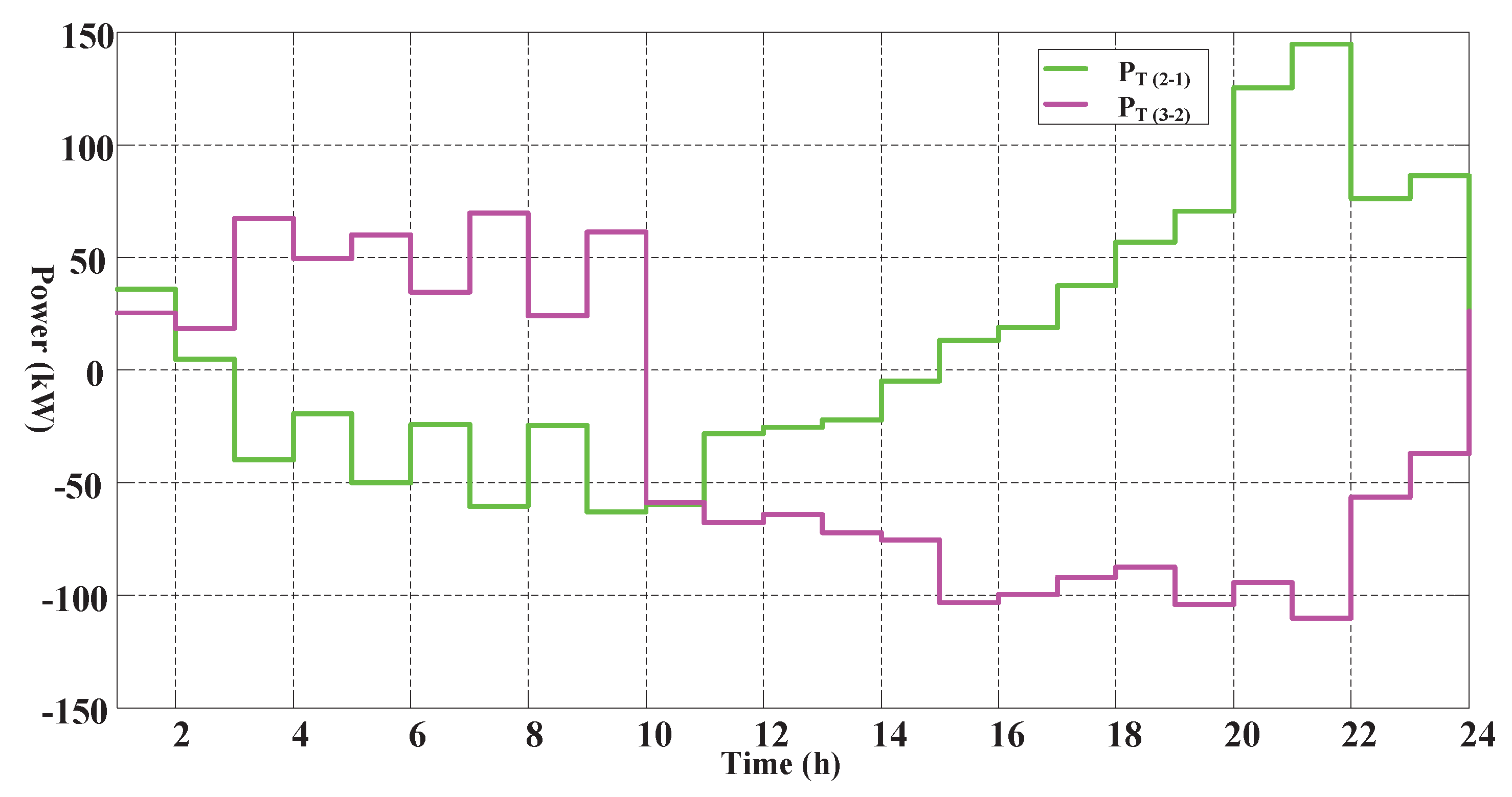
Exchanging powers via different DC-links are shown in Figure 7. (2-1) and (3-2) are respectively denoted the exchanging power between and (positive means energy transmitted from to ) and exchanging power between and (positive means energy transmitted from to ). In Figure 7, the results show that the DC-links have acted as efficient bridges for the inner energy sharing between the MGs. In the first two hours, energy is transferred from to due to the heavy load in . Furthermore, from 3:00 to 10:00, both and have transferred energy to to satisfy the fluctuating heavy load. After that, with surplus solar and wind energy and light load in , the power flow directions of DC-links have been changed at 10:00 and 15:00 to meet the growing load demand in and . Finally, after 21:00, the growing load demand in results in decreasing the exchanging power transferred from .
In order to test the effectiveness by using the stochastic programming, the scheduling costs under stochastic and deterministic programming are shown in Table 2. The scheduling cost reduction reaches to 11.82% by using stochastic programming, as taken the uncertainties of RES and loads into consideration.
Furthermore, the added value of co-operation between different MGs should be analyzed. From the viewpoint of MG owners, the network tariff can be ignored and the energy purchased from the adjacent MGs could be cheaper than the one from the distribution network, thus it is more economic for the MGs to work as a coalition via DC-links. The comparison between the separated mode and co-operation mode of MGs is shown in Table 3. In the separated mode, we assume that the DC-links are opened, and each MG trades energy with the distribution network directly when there is plenty or lack of renewable energy. The results show that the scheduling cost of separated MGs is 6.45% higher than the co-operated MGs.
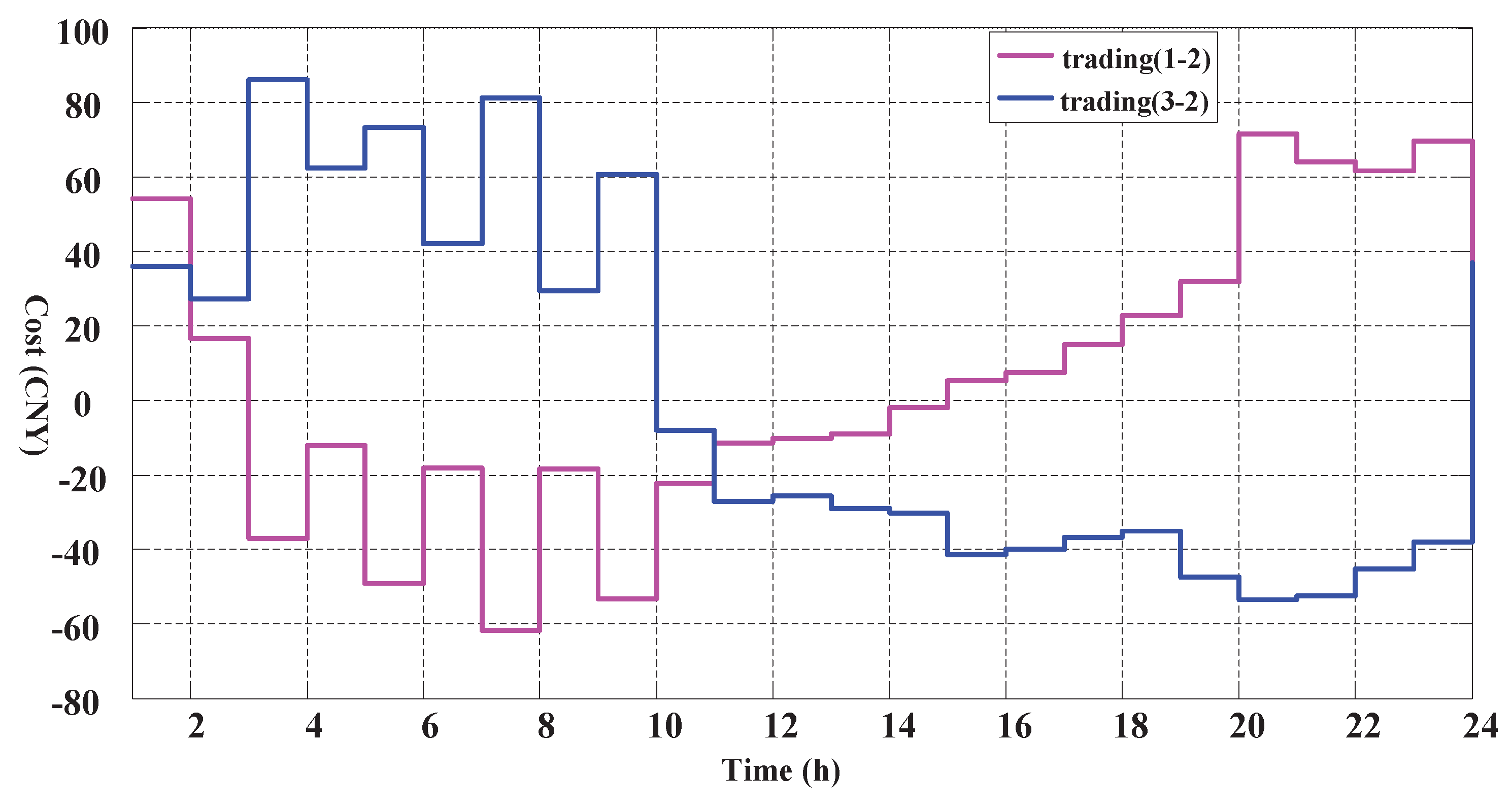
6.2. Results of Billing Mechanism
After a day’s operation, the MCO should redistribute the cost of each MG according to the exchanged energy via DC-links. The results of billing mechanism are shown in Figure 8, where (1-2) represents the cost transacted from to , and (3-2) represents 6205640the cost transacted from to . In the first two hours, has to buy energy from to meet the heavy load demand at a higher price. From 3:00 to 9:00, the fluctuating heavy load demand in leads to a high cost paid to both and . From 10:00 to 18:00, there is plenty of solar and wind energy and light load in , thus and can purchase electricity from to meet their growing load demands. After 21:00, although the exchanged powers are sharply reduced, the transacted cost still maintain on a high level due to higher generation cost in this time period.
6.3. Results of Event Triggered Dynamic Reconfiguration
The results of event triggered dynamic reconfiguration are shown in Table 4. We can see that the states of switches are changed two times and the reconfiguration actions are carried out at 1:00 and 21:00.
In order to test the effectiveness of the event trigger, two scenarios are taken as comparison objects: (i) fixed time period for each 8 h (i.e., 3 times per day), (ii) fixed time period for each 24 h (i.e., 0 time per day). As can be seen in Table 5, the results of two indicators (power loss and cost of power loss) show that the event trigger method has better performance, in which the power loss reductions reach to 23.75% and 33.80%, as compared to the two scenarios.
7. Conclusions
In this paper, we have proposed a multi-party optimal operation method for distribution networks containing DC-linked MGs, which has integrated the reconfiguration problem of distribution network and the optimal scheduling problem of multi-MG in a unified framework. Firstly, we have modelled the energy sharing between MGs as a optimal scheduling in a MG coalition by using the stochastic programming, and have designed a billing mechanism for the energy sharing. Using the three interconnected MGs as a testing case, we have shown that the model can efficiently deal with the uncertainty features of RES and loads, and the billing mechanism can fairly distribute the operation cost among MGs. Moreover, we have further proposed an event triggered method for dynamic reconfiguration of distribution networks. Finally, the method has been tested by using a modified IEEE-33 nodes system with the three interconnected MGs. The results show that event triggered method has better performance compared to the traditional fixed time period reconfigurations, and the power loss has reduced for 33.80% maximally. In the future works, the proposed method can be extended and improved in several aspects. First, the islanding situation of the MGs is a possible scenario for the operation, it would be interesting to consider the island operation and analyze the behavior by using this framework. Second, the types of DERs or other components can be involved, such as energy storage [34], fuel cell [30], heat pump [35], and electric vehicles [36].
Acknowledgments
This work was supported by the Fundamental Research Funds for the Central Universities (No. 2015ZD02).
Author Contributions
The paper was a collaborative effort between the authors. Nian Liu, Bin Guo contributed collectively to the theoretical analysis, modeling, simulation and manuscript preparation.
Conflicts of Interest
The authors declare no conflict of interest.
References
- Capitanescu, F.; Ochoa, L.F.; Margossian, H.; Hatziargyriou, N.D. Assessing the Potential of Network Reconfiguration to Improve Distributed Generation Hosting Capacity in Active Distribution Systems. IEEE Trans. Power Syst. 2015, 30, 346–356. [Google Scholar] [CrossRef]
- Liu, N.; Tang, Q.; Zhang, J.; Fan, W.; Liu, J. A hybrid forecasting model with parameter optimization for short-term load forecasting of micro-grids. Appl. Energy 2014, 129, 336–345. [Google Scholar]
- Cingoz, F.; Elrayyah, A.; Sozer, Y. Optimized Settings of Droop Parameters Using Stochastic Load Modeling for Effective DC Microgrids Operation. IEEE Trans. Ind. Appl. 2017, 53, 1358–1371. [Google Scholar] [CrossRef]
- Che, L.; Zhang, X.; Shahidehpour, M.; Alabdulwahab, A.; Abusorrah, A. Optimal Interconnection Planning of Community Microgrids With Renewable Energy Sources. IEEE Trans. Smart Grid 2015, 8, 1054–1063. [Google Scholar] [CrossRef]
- Liu, N.; Yu, X.; Wang, C.; Li, C.; Ma, L.; Lei, J. Energy-Sharing Model With Price-Based Demand Response for Microgrids of Peer-to-Peer Prosumers. IEEE Trans. Power Syst. 2017, 32, 3569–3583. [Google Scholar]
- Liu, N.; Yu, X.; Wang, C.; Wang, J. Energy Sharing Management for Microgrids With PV Prosumers: A Stackelberg Game Approach. IEEE Trans. Ind. Inform. 2017, 13, 1088–1098. [Google Scholar] [CrossRef]
- Nutkani, I.U.; Loh, P.C.; Blaabjerg, F. Distributed Operation of Interlinked AC Microgrids with Dynamic Active and Reactive Power Tuning. IEEE Trans. Ind. Appl. 2013, 49, 2188–2196. [Google Scholar]
- Koyanagi, K.; Hida, Y.; Yokoyama, R.; Nagata, S.; Nakao, K.; Hirai, T. Electricity Cluster-Oriented Network: A grid-Independent And Autonomous Aggregation of Micro-Grids. In Proceedings of the International Symposium on Modern Electric Power Systems, Wrocaw, Poland, 20–22 September 2010; pp. 1–6. [Google Scholar]
- Chaudhary, S.K.; Guerrero, J.M.; Teodorescu, R. Enhancing the Capacity of the AC Distribution System Using DC Interlinks: A Step Toward Future DC Grid. IEEE Trans. Smart Grid 2015, 6, 1722–1729. [Google Scholar]
- Romero-Ramos, E.; Gomez-Exposito, A.; Marano-Marcolini, A.; Maza-Ortega, J.M.; Martinez-Ramos, J.L. Assessing the loadability of active distribution networks in the presence of DC controllable links. IET Gener. Transm. Distrib. 2011, 5, 1105–1113. [Google Scholar] [CrossRef]
- Cao, W.; Wu, J.; Jenkins, N.; Wang, C.; Green, T. Operating principle of Soft Open Points for electrical distribution network operation. Appl. Energy 2016, 164, 245–257. [Google Scholar] [CrossRef]
- Zhao, B.; Shi, Y.; Dong, X.; Luan, W.; Bornemann, J. Short-Term Operation Scheduling in Renewable-Powered Microgrids: A Duality-Based Approach. IEEE Trans. Sustain. Energy 2014, 5, 209–217. [Google Scholar] [CrossRef]
- Nikmehr, N.; Ravadanegh, S.N. Optimal Power Dispatch of Multi-Microgrids at Future Smart Distribution Grids. IEEE Trans. Smart Grid 2015, 6, 1648–1657. [Google Scholar] [CrossRef]
- Marzband, M.; Parhizi, N.; Savaghebi, M.; Guerrero, J.M. Distributed Smart Decision-Making for a Multimicrogrid System Based on a Hierarchical Interactive Architecture. IEEE Trans. Energy Convers. 2016, 31, 637–648. [Google Scholar] [CrossRef]
- Liu, N.; Wang, J.; Wang, L. Distributed energy management for interconnected operation of combined heat and power-based microgrids with demand response. J. Mod. Power Syst. Clean Energy 2017, 5, 1–11. [Google Scholar] [CrossRef]
- Liu, N.; Wang, C.; Cheng, M.; Wang, J. A Privacy-Preserving Distributed Optimal Scheduling for Interconnected Microgrids. Energies 2016, 9, 1031. [Google Scholar] [CrossRef]
- Farzin, H.; Fotuhi-Firuzabad, M.; Moeini-Aghtaie, M. Enhancing Power System Resilience Through Hierarchical Outage Management in Multi-Microgrids. IEEE Trans. Smart Grid 2016, 7, 2869–2879. [Google Scholar] [CrossRef]
- Gholami, A.; Shekari, T.; Aminifar, F.; Shahidehpour, M. Microgrid Scheduling With Uncertainty: The Quest for Resilience. IEEE Trans. Smart Grid 2016, 7, 2849–2858. [Google Scholar] [CrossRef]
- Rao, R.S.; Ravindra, K.; Satish, K.; Narasimham, S.V.L. Power Loss Minimization in Distribution System Using Network Reconfiguration in the Presence of Distributed Generation. IEEE Trans. Power Syst. 2013, 28, 317–325. [Google Scholar] [CrossRef]
- Esmaeilian, H.R.; Fadaeinedjad, R. Energy Loss Minimization in Distribution Systems Utilizing an Enhanced Reconfiguration Method Integrating Distributed Generation. IEEE Syst. J. 2015, 9, 1430–1439. [Google Scholar] [CrossRef]
- Elmitwally, A.; Elsaid, M.; Elgamal, M.; Chen, Z. A Fuzzy-Multiagent Service Restoration Scheme for Distribution System With Distributed Generation. IEEE Trans. Sustain. Energy 2015, 6, 810–821. [Google Scholar] [CrossRef]
- Koutsoukis, N.C.; Siagkas, D.O.; Georgilakis, P.S.; Hatziargyriou, N.D. Online Reconfiguration of Active Distribution Networks for Maximum Integration of Distributed Generation. IEEE Trans. Autom. Sci. Eng. 2017, 14, 437–448. [Google Scholar] [CrossRef]
- Liu, J.; Chiang, H.D. Maximizing Available Delivery Capability of Unbalanced Distribution Networks for High Penetration of Distributed Generators. IEEE Trans. Power Deliv. 2017, 32, 1196–1202. [Google Scholar] [CrossRef]
- de Quevedo, P.M.; Contreras, J.; Rider, M.J.; Allahdadian, J. Contingency Assessment and Network Reconfiguration in Distribution Grids Including Wind Power and Energy Storage. IEEE Trans. Sustain. Energy 2015, 6, 1524–1533. [Google Scholar] [CrossRef]
- Elmitwally, A.; Elsaid, M.; Elgamal, M.; Chen, Z. A Fuzzy-Multiagent Self-Healing Scheme for a Distribution System With Distributed Generations. IEEE Trans. Power Syst. 2015, 30, 2612–2622. [Google Scholar] [CrossRef]
- Shamsi, P.; Xie, H.; Longe, A.; Joo, J.Y. Economic Dispatch for an Agent-Based Community Microgrid. IEEE Trans. Smart Grid 2016, 7, 2317–2324. [Google Scholar] [CrossRef]
- Li, J.; Wu, L. Optimal Operation for Community Based Multi-Party Microgrid in Grid-Connected and Islanded Modes. IEEE Trans. Smart Grid 2017, PP, 1. [Google Scholar] [CrossRef]
- Xia, S.; Zhou, M.; Li, G.; Liu, Y.; Xiang, M. On Spinning Reserve Determination and Power Generation Dispatch Optimization for Wind Power Integration Systems. In Proceedings of the 2012 IEEE Power and Energy Society General Meeting, San Diego, CA, USA, 22–26 July 2012; pp. 1–7. [Google Scholar]
- Zhang, L.; Tang, W.; Liang, J.; Cong, P.; Cai, Y. Coordinated Day-Ahead Reactive Power Dispatch in Distribution Network Based on Real Power Forecast Errors. IEEE Trans. Power Syst. 2016, 31, 2472–2480. [Google Scholar] [CrossRef]
- Tan, S.; Xu, J.X.; Panda, S.K. Optimization of Distribution Network Incorporating Distributed Generators: An Integrated Approach. IEEE Trans. Power Syst. 2013, 28, 2421–2432. [Google Scholar] [CrossRef]
- Subathra, M.S.P.; Selvan, S.E.; Victoire, T.A.A.; Christinal, A.H.; Amato, U. A Hybrid With Cross-Entropy Method and Sequential Quadratic Programming to Solve Economic Load Dispatch Problem. IEEE Syst. J. 2015, 9, 1031–1044. [Google Scholar] [CrossRef]
- Baran, M.E.; Wu, F.F. Network reconfiguration in distribution systems for loss reduction and load balancing. IEEE Trans. Power Deliv. 1989, 4, 1401–1407. [Google Scholar] [CrossRef]
- Growe-Kuska, N.; Heitsch, H.; Romisch, W. Scenario Reduction and Scenario Tree Construction for Power Management Problems. In Proceedings of the IEEE Bologna Power Tech Conference, Bologna, Italy, 23–26 June 2003; Volume 3, p. 7. [Google Scholar]
- Shi, W.; Xie, X.; Chu, C.C.; Gadh, R. A Distributed Optimal Energy Management Strategy for Microgrids. In Proceedings of the IEEE International Conference on Smart Grid Communications, Venice, Italy, 3–6 November 2014; pp. 200–205. [Google Scholar]
- Angelis, F.D.; Boaro, M.; Fuselli, D.; Squartini, S.; Piazza, F.; Wei, Q. Optimal Home Energy Management Under Dynamic Electrical and Thermal Constraints. IEEE Trans. Ind. Inform. 2013, 9, 1518–1527. [Google Scholar] [CrossRef]
- Liu, N.; Chen, Q.; Liu, J.; Lu, X.; Li, P.; Lei, J.; Zhang, J. A Heuristic Operation Strategy for Commercial Building Microgrids Containing EVs and PV System. IEEE Trans. Ind. Electron. 2015, 62, 2560–2570. [Google Scholar] [CrossRef]
Figure 1.
Schematic diagram of interactions between different parties.

Figure 2.
Distribution network with Direct Current (DC)-linked Microgrids (MGs).
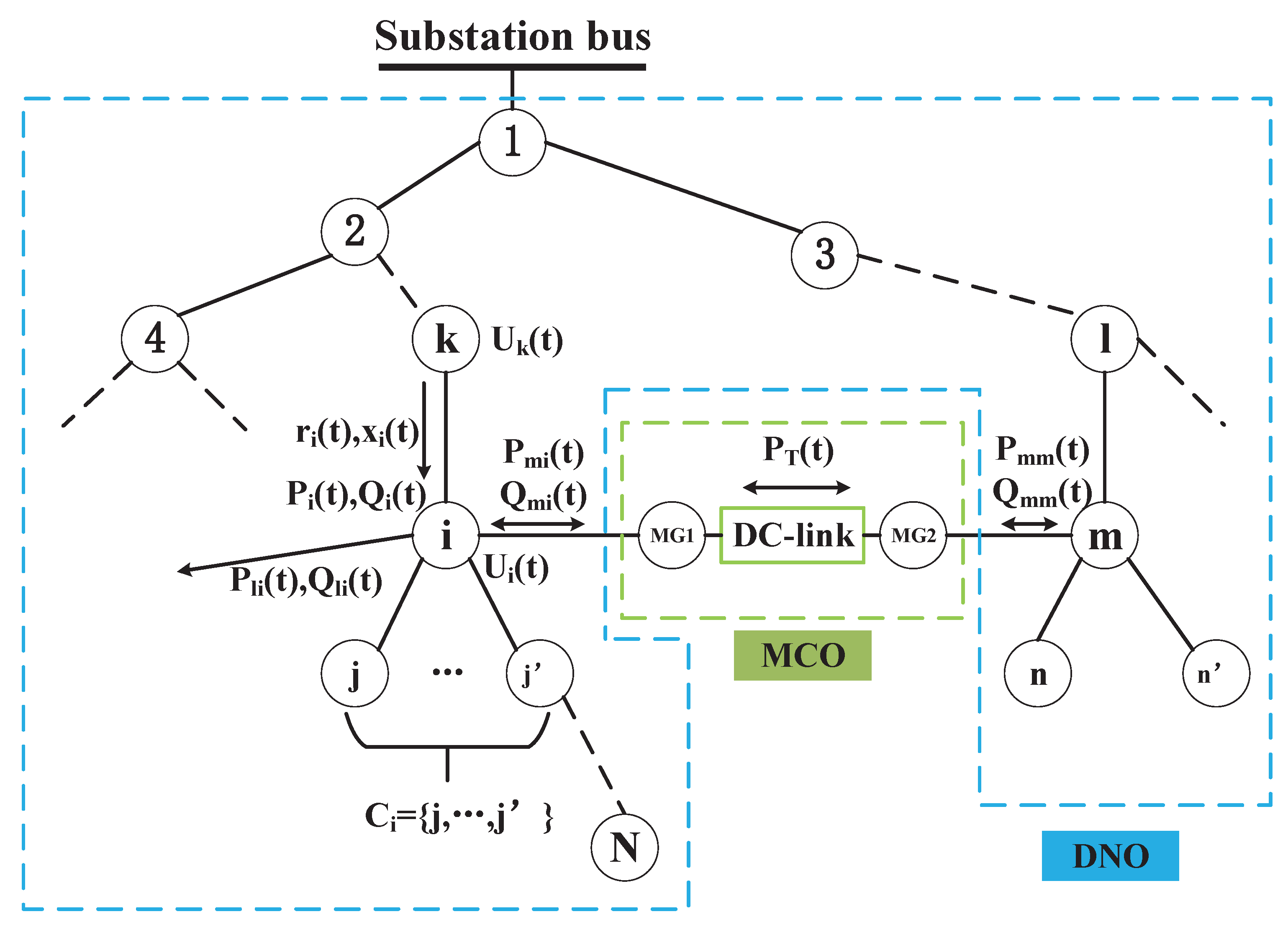
Figure 3.
Flowchart of Reconfiguration Model.
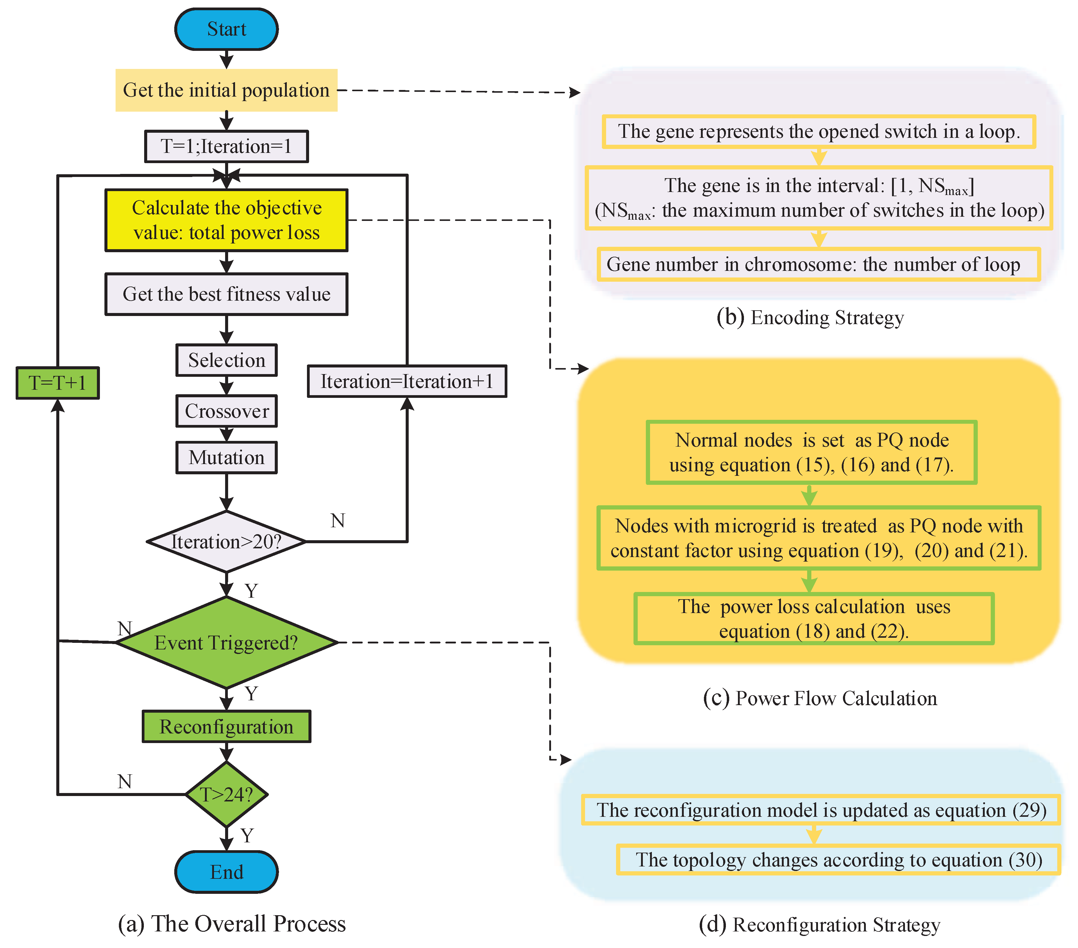
Figure 4.
Example of operation cost of distributed energy resources (DERs) in an MG.

Figure 5.
IEEE 33-node test system containing multi-microgrid connected via DC-link.
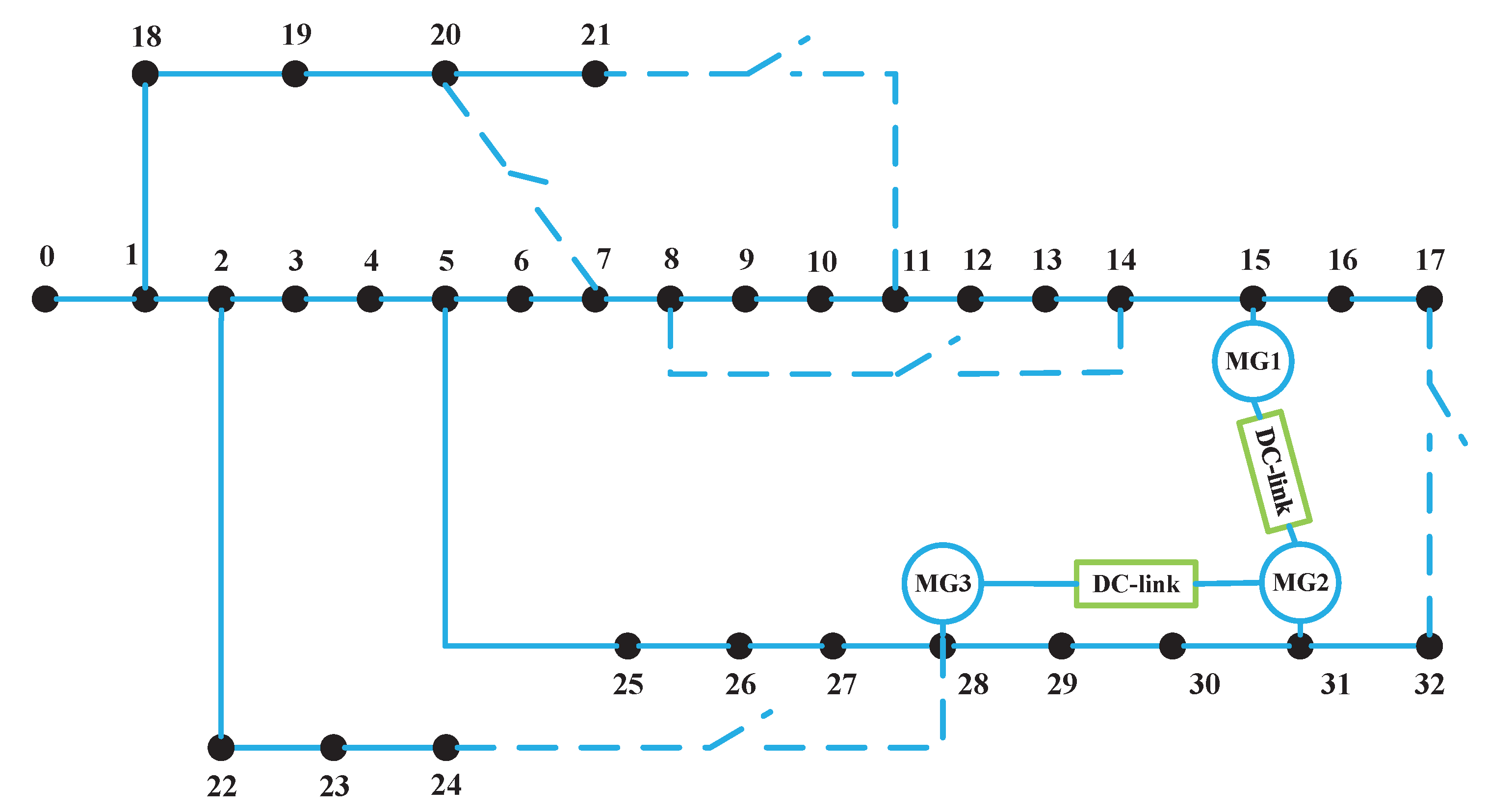
Figure 6.
Results of stochastic scheduling of 3 MGs.

Figure 7.
Exchanging power on DC-links.

Figure 8.
Results of cost transactions between MGs.

Table 1.
Capacity of distributed energy resources (DERs) in each Microgrids (MG).
| Microgrid | Connected Node | Load (kW) | Microturbine (kW) | PV (kW) | WT (kW) |
|---|---|---|---|---|---|
| MG1 | 15 | 60 | — | 0–60 | — |
| MG2 | 31 | 210 | 100 | 0–60 | 0–60 |
| MG3 | 28 | 120 | 100 | 0–70 | — |
Table 2.
Mean scheduling cost using stochastic and deterministic programming.
| Deterministic Programming (CNY/h) | Stochastic Programming (CNY/h) | Reduction Rate (%) |
|---|---|---|
| 220.60 | 194.53 | 11.82 |
Table 3.
Comparison of mean scheduling cost between separated mode and co-operated mode.
| Separated Mode (CNY/h) | Co-Operated Mode (CNY/h) | Reduction Rate (%) |
|---|---|---|
| 207.95 | 194.53 | 6.45 |
Table 4.
Results of event triggered reconfiguration scheme.
| Time Period | Switched Opend |
|---|---|
| 1:00–20:00 | 6–7 11–21 10–11 30–31 26–27 |
| 21:00–24:00 | 6–7 8–9 13–14 30–31 24–28 |
Table 5.
The mean cost and power loss under normal and dynamic reconfiguration.
| Reconfiguration Times | Power Loss Cost (CNY) | Power Loss (kWh) | Power Loss Reduction (%) |
|---|---|---|---|
| 0 | 1173.35 | 182.9549 | – |
| 3 | 894.68 | 139.5038 | 23.75 |
| 2 | 876.94 | 121.1111 | 33.80 |
© 2017 by the authors. Licensee MDPI, Basel, Switzerland. This article is an open access article distributed under the terms and conditions of the Creative Commons Attribution (CC BY) license (http://creativecommons.org/licenses/by/4.0/).
Share and Cite
MDPI and ACS Style
Liu, N.; Guo, B. Multi-Party Optimal Operation for Distribution Networks Containing DC-Linked Microgrids: Integrated Network Reconfigurations and Energy Sharing. Appl. Sci. 2017, 7, 1194. https://doi.org/10.3390/app7111194
AMA Style
Liu N, Guo B. Multi-Party Optimal Operation for Distribution Networks Containing DC-Linked Microgrids: Integrated Network Reconfigurations and Energy Sharing. Applied Sciences. 2017; 7(11):1194. https://doi.org/10.3390/app7111194
Chicago/Turabian StyleLiu, Nian, and Bin Guo. 2017. "Multi-Party Optimal Operation for Distribution Networks Containing DC-Linked Microgrids: Integrated Network Reconfigurations and Energy Sharing" Applied Sciences 7, no. 11: 1194. https://doi.org/10.3390/app7111194
Note that from the first issue of 2016, this journal uses article numbers instead of page numbers. See further details here.