Article

Multidisciplinary Design Optimization of a Swash-Plate Axial Piston Pump

1
School of Mechanical Engineering, Tongji University, Shanghai 200092, China
2
School of Mechanical and Vehicle Engineering, Changzhou Institute of Technology, Changzhou 213002, China
3
College of Environmental Science and Engineering, Tongji University, Shanghai 200092, China
*
Author to whom correspondence should be addressed.
Appl. Sci. 2016, 6(12), 399; https://doi.org/10.3390/app6120399
Submission received: 30 October 2016 / Revised: 22 November 2016 / Accepted: 24 November 2016 / Published: 19 December 2016

Abstract

:
This work proposes an MDO (multidisciplinary design optimization) procedure for a swash-plate axial piston pump based on co-simulation and integrated optimization. The integrated hydraulic-mechanical model of the pump is built to reflect its actual performance, and a hydraulic-mechanical co-simulation is conducted through data exchange between different domains. The flow ripple of the pump is optimized by using a MDO procedure. A CFD (Computational Fluid Dynamics) simulation of the pump’s flow field is done, which shows that the hydrodynamic shock of the pump is improved after optimization. To verify the MDO effect, an experimental system is established to test the optimized piston pump. Experimental results show that the simulated and experimental curves are similar. The flow ripple is improved by the MDO procedure. The peak of the pressure curve is lower than before optimization, and the pressure pulsation is reduced by 0.21 MPa, which shows that the pressure pulsation is improved with the decreasing of the flow ripple. Comparing the experimental and simulation results shows that MDO method is effective and feasible in the optimization design of the pump.

1. Introduction

The piston pump is widely used due to its high power density, high efficiency and controllable flow. The working conditions of a piston pump generally involve coupled-field behaviors [1,2], combining two or more energy domains. Coupling effects have be comprehensively considered. The coupled-field behaviors determine the design complexity of a piston pump [3,4]. The traditional method to develop a piston pump including material preparation, structure design, manufacturing, feedback modification and experiment is a complex and time-consuming process, which makes it hard to produce a highly efficient design. Therefore, it is beneficial to study the design method of piston pump.
Recently, virtual prototyping technology for piston pumps has made great process, becoming a new design approach. Industries have improved design efficiency by using virtual prototyping technology. Modeling and numerical simulation are widely accepted as cost-effective and timesaving alternatives to the experimental approach [5]. Kim et al. [6] proposed a pressure control method to minimize power consumption in supplying constant-pressure oil to a valve-controlled hydraulic cylinder. Xu et al. [7] presented a parametric study on flow ripple for guiding the design of a piston pump, and the computational accuracy is improved for analyzing the parametric effects on flow ripple and optimizing the design of the pump. Lee et al. [8] built a new mathematical model for the analysis and diagnosis of a high-pressure reciprocating pump system. The value of the damage parameter over 300 cycles is calculated by the model, and its probability density function is obtained for diagnosis and prognosis. Cho [9] studied the optimum design for the valve plate of a swash plate-type oil hydraulic piston pump, and the optimum design is realized by analyzing the stress on the valve plate of a hydraulic axial piston pump. Mandal et al. [10] optimized the pressure compensator design for a swash plate axial piston pump using a simulation approach. Bae et al. [11] employed simulation to reduce the pressure/flow pulsation of a swash plate type variable piston pump. Song et al. [12] conducted a multidisciplinary optimization for a butterfly valve, and the accuracy of the optimization is verified by an experiment. Zhao et al. [13] proposed a multi-objective and multidisciplinary optimization of a double-channel pump. Shi et al. [14] studied the design of axial flow pump modification and its effect based on CFD (Computational Fluid Dynamics) calculation. It is seen that design optimization method combining integrated co-simulation and optimization can find effective trade-off solutions for complicated and conflicting design criteria [15], considering the multidisciplinary coupling effects of structural field, temperature field, and working environment [16,17]. Singh and Nataraj [18] proposed a methodology to find the near optimum combination of pump operating variables using the GA and Taguchi method. Kim et al. [19] developed an optimal structure for a high-pressure GDI (Gasoline Direct Injection) pump. Mao et al. [20] optimized the friction coefficient for hydraulic components. Wang et al. [21] proposed an optimization design for a throttle valve based on CFD simulation and the response surface method.
In this work, an MDO (multidisciplinary design optimization) of a swash-plate axial piston pump is conducted based on simulation technology and integrated optimization. The accuracy of the simulation model is improved and coupling analysis is achieved by data exchange among different domains. On the basis of co-simulation, an automatic optimization is done using an MDO approach to improve the pump’s performance. The paper is organized as follows: in Section 1, some related research on MDO and the piston pump is introduced. In Section 2, the working principle of the pump is analyzed in theory, including the motion of pistons and the flow characteristics. In Section 3, AMESim (version 13, LMS Imagine. Lab AMESim, Leuven, Belgium) is employed to define the hydraulic model, while the dynamic model is defined by ADAMS (version 2005, MSC Software Corporation, Newport Beach, CA, USA), then co-simulation is conducted by the two models as the hydraulic-mechanical coupling is taken into consideration. In Section 4, based on the co-simulation model obtained in Section 4, the integrated optimization is conducted, and the flow ripples are optimized by using SQP (Sequential Quadratic Programming) algorithm. In Section 5, according to the optimized results in Section 4, the CFD model is built to analyze the pressure distribution in the flow field. In Section 6, a comparison experiment is performed to verify the result of the MDO of the pump. The experimental and simulation results are compared, which indicate that multidisciplinary design optimization is effective and feasible in the optimization design of piston pump performance. In the last section, the research and its results are summarized.

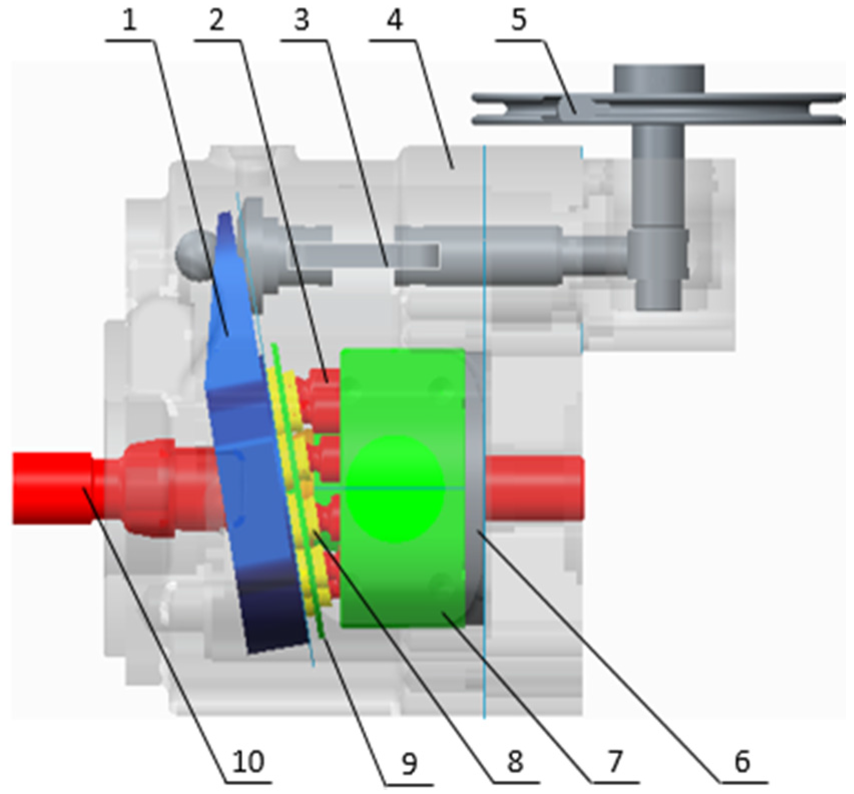
2. Working Principle of the Pump

A swash-plate axial piston pump is focused on in this work, as shown in Figure 1. When a motor drives the spindle, the pistons rotate with the spindle and meanwhile perform reciprocating motion in the cylinder. When a piston rotates from TDC (top dead center) to BDC (bottom dead center), it moves to the right and delivers the oil out of the high-pressure chamber. Then, the piston moves to left and sucks the oil into the low-pressure chamber while it rotates from BDC to TDC. Each piston chamber completes oil absorption and oil expulsion once a cycle. The displacement and working direction can be changed by rotating the angle control valve [22,23].

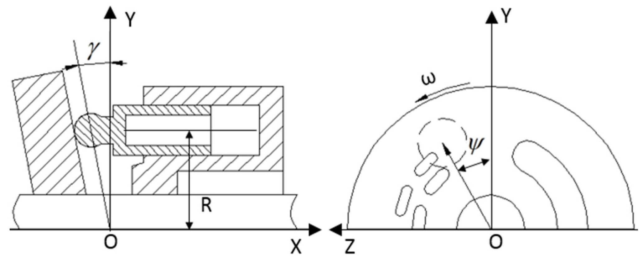
2.1. Motion Analysis

A coordinate system, as shown in Figure 2, is established to analyze the piston motion. When the piston locates on the TDC, the rotation angle ψ of the spindle is defined as 0° and the piston’s displacement in X direction is the minimum displacement X min :
X min = R tan γ
where R is the radius of the piston distribution circle; γ is the swash-plate’s inclination.
When the cylinder rotates with ψ , the piston’s displacement in the X direction is:
X = R cos ψ tan γ
The relative displacement of the piston in the X direction is:
H = X X min = R tan γ ( 1 cos ψ )
where the rotation angle of the cylinder is ψ = ω t ; ω is the angular velocity of the cylinder.
Therefore, the piston’s velocity in the X direction is:
V x = d H d t = R ω tan γ sin ψ
For the pump in this work, R = 29 mm , γ = 12.5 ° , n 0 = 1500 r / min . According to Equations (1)–(4), the motion equations of pistons in the X direction are:
X = 6.43 cos 157 t
V X = 1009.38 sin 157 t

2.2. Flow Analysis

According to Equations (1)–(4), the theoretical flow of a piston chamber is:
q i = S v = S R ω tan γ sin ψ i
where S is the cross-sectional area of the piston, and S = π 4 d 2 ; d is the piston’s diameter.
Therefore, the theoretical instantaneous flow Q of the pump is:
Q = i = 1 n q i = i = 1 n S v i = π 4 d 2 R ω tan γ i = 1 n sin ψ i = π 4 d 2 R ω tan γ i = 1 n sin { ψ 1 + 2 β ( i 1 ) }
The average flow of the pump is:
Q ¯ = S H max N n 0 = π 2 d 2 R tan γ N n 0
where n is the number of pistons in the high-pressure chamber; N is the total number of pistons; H max is the maximum displacement of pistons in X direction; n 0 is the spindle speed, and 2 β = 2 π N .
The swash-plate axial pump that is researched in this work contains 10 pistons. Therefore, N = 10 and β = 18 ° . According to Equation (8), the theoretical maximum flow, minimum flow and average flow of the pump are shown as follows:
Q 10 max = π 4 d 2 R ω tan γ i = 1 n sin { β + 2 β ( i 1 ) } = 10 i = 1 5 sin { 18 + 36 ( i 1 ) } = 32.35 ( L / min )
Q 10 min = π 4 d 2 R ω tan γ i = 1 n sin { 0 + 2 β ( i 1 ) } = 10 i = 1 5 sin { 0 + 36 ( i 1 ) } = 30.76 ( L / min )
Q ¯ 10 = S H max N n 0 = 14.5 2 π 2 × 29 tan ( 12.5 ° ) × 10 × 1500 = 31.83 ( L / min )
According to Equations (10) and (11), the theoretical flow ripple rate of the piston pump is:
Δ Q 10 = Q 10 max Q 10 min = k [ i = 1 n sin { β + 2 β ( i 1 ) } i = 1 n sin { 0 + 2 β ( i 1 ) } ] = k 2 sin 2 ( β 2 ) sin β
σ 10 = Δ Q Q max = k 2 sin 2 ( β 2 ) sin β k i = 1 n sin { β + 2 β ( i 1 ) } = 2 sin 2 ( β 2 ) = 4 . 91 %
where k is a constant, and k = π 4 d 2 R ω tan γ .
The theoretical flow ripple rate obtained from Equations (13) and (14) is not involved in the influence of grooves, damping holes and the compressibility of the oil. Therefore, integrated hydraulic-mechanical modeling and co-simulation are proposed.

3. Integrated Hydraulic-Mechanical Modeling and Co-Simulation

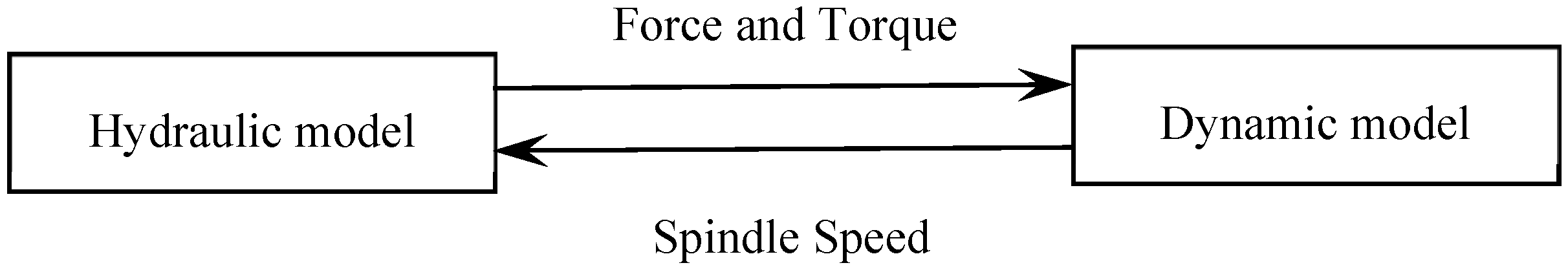
3.1. Hydraulic-Mechanical Coupling Analysis

The hydraulic-mechanical coupling considers the interaction between hydraulic oil and pistons in motion to obtain more accurate simulation results. In the coupling simulation, the mechanical system and hydraulic system transfer related parameters each other, which links the two systems.
The multi-body dynamic model established by the Lagrangian method in mechanical system is:
d d t ( K q i j ) K q i j + i = 1 n Ψ i q i j λ i = F i j    ( j = 1 , 2 , 3 , , 6 )
Ψ i = 0
where K is the kinetic energy; q i j is the generalized coordinate of the system; F i j is the generalized force on the generalized coordinate; λ i is m × 1 array of the Lagrange multiplier, Ψ i is the constraint equation of the system.
Generally, the mathematical model of a hydraulic system can be described by higher order differential equation, block diagram, state space expression and so on. The flow balance equation of hydraulic component is:
Q = C d A 2 ( P 2 P 1 ) ρ
where Q is the flow; C d is the flow coefficient, which is related to the Reynolds number, and C d = 0.7 in this paper; A is the throttling area; P 2 P 1 is the pressure difference of the orifice; ρ is the density of the oil.
As mentioned above, hydraulic-mechanical coupling of the piston pump is described by Equations (15) and (17). The generalized force F i j is the force of the piston in the model, which is calculated by the pressure described in Equation (17) and the cross-sectional areas of pistons. Meanwhile, the flow Q is decided by the motion of pistons described in Equation (15). These data are exchanged in the two models, so that hydraulic-mechanical modeling and co-simulation are achieved.

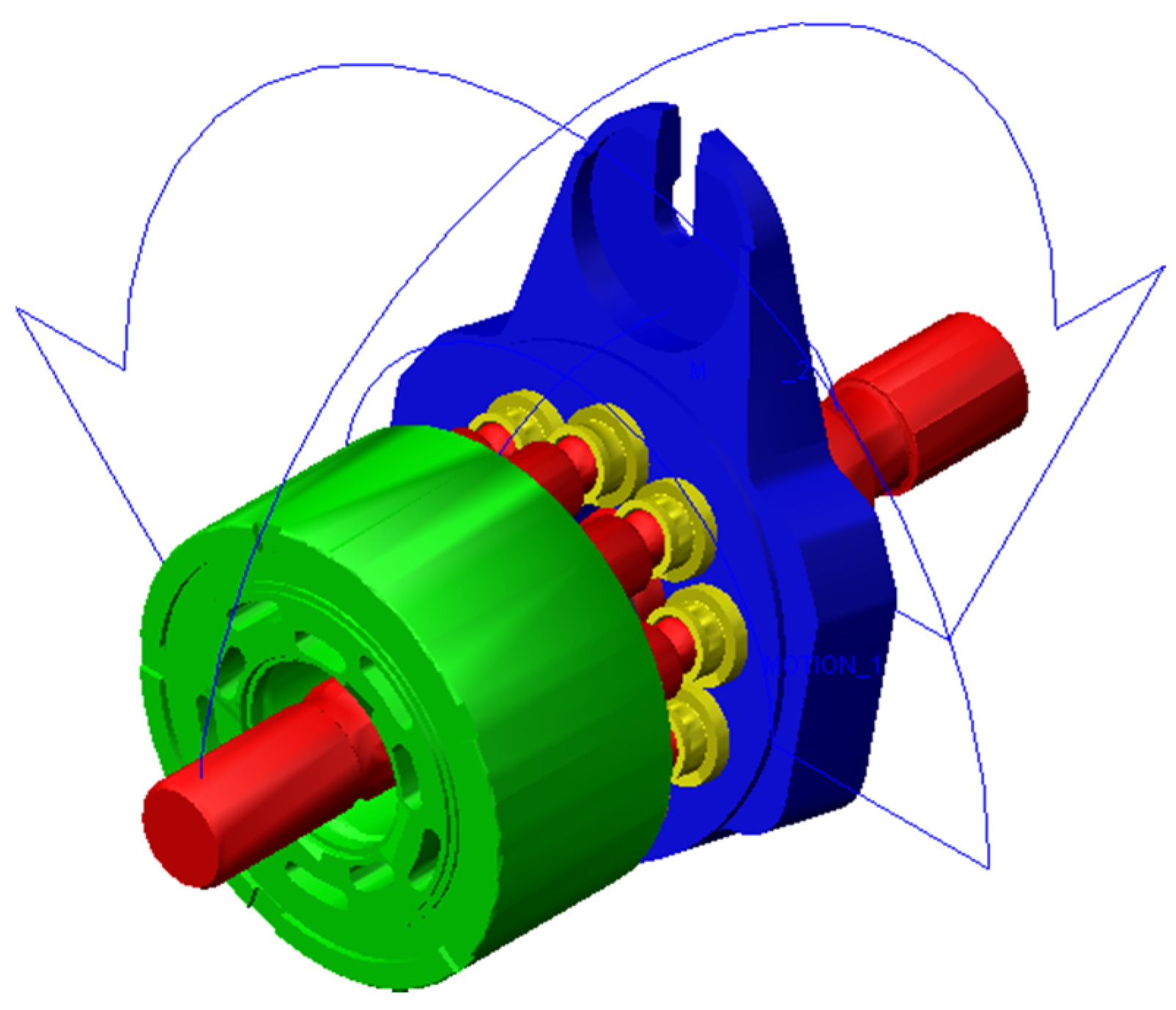
3.2. Integrated Modeling
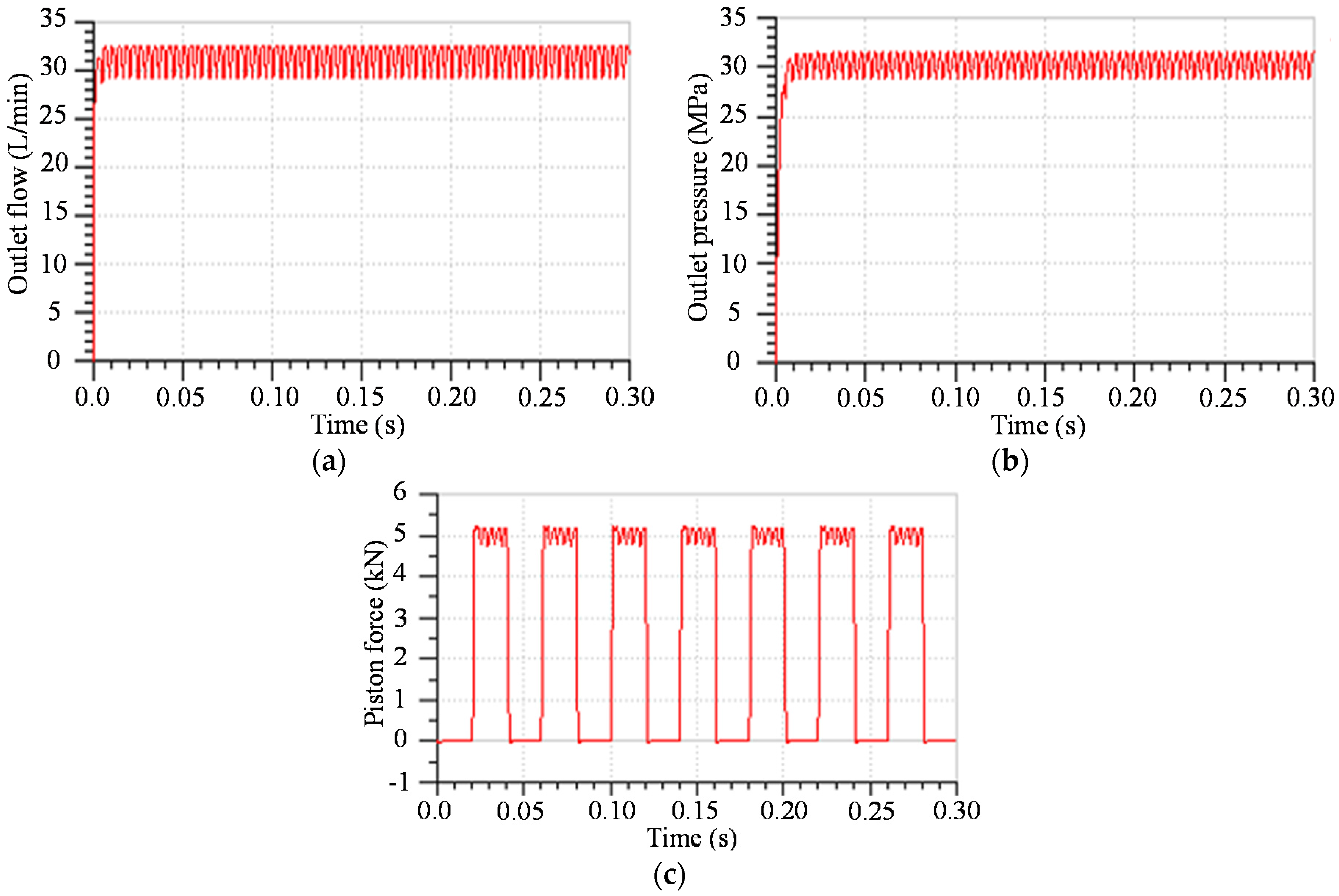
The 3D model of the pump is built to perform a dynamic simulation. In the working process of the pump, the main movement is the spindle’s rotation, and the auxiliary movement is the swash-plate’s rotation. Therefore, two drives are defined. The dynamic model is shown in Figure 3.
Compared with dynamic simulation or hydraulic simulation, co-simulation can exchange real-time data through a data interface between disciplines and link the dynamic model and hydraulic model to realize hydraulic-mechanical coupling simulation. In this work, as far as the hydraulic performance of the pump is concerned, hydraulic model is selected as the control platform of the co-simulation. In order to realize data exchange in co-simulation, axial hydraulic pressures F 1 , F 2 , …, F 10 of the pistons and the load torque T of spindle are defined as the input variables of the dynamic model, and the spindle speed n 0 is defined as the input variable in the hydraulic model, as shown in Figure 4.
The piston’s model is built and packed as a supercomponent. The pistons, load and drive are assembled to be a hydraulic system model of the pump, and data exchange is built to transfer data between two models.

3.3. Co-Simulation

The simulation of the hydraulic-mechanical coupling is conducted. The simulation parameters are shown in Table 1. The results are shown in Figure 5.
It is seen that the maximum flow is 30.60 L/min, the minimum flow is 29.19 L/min and average flow is 30.90 L/min, which are close to the theoretical values calculated in Section 2.2. The flow ripple coefficient is 11.04%, which is far greater than the theoretical value calculated in Section 2.2, as the compressibility of the oil and the ripple coupling of the piston chambers are considered.
As the pump is the power source of the hydraulic system, the flow ripple caused by the pump could result in vibration and decreased life. The influence may be transmitted to subordinate components and affect the whole hydraulic system. Therefore, it is important to improve the working quality of the pump by reducing the flow ripple.

4. Multidisciplinary Design Optimization (MDO) of the Pump
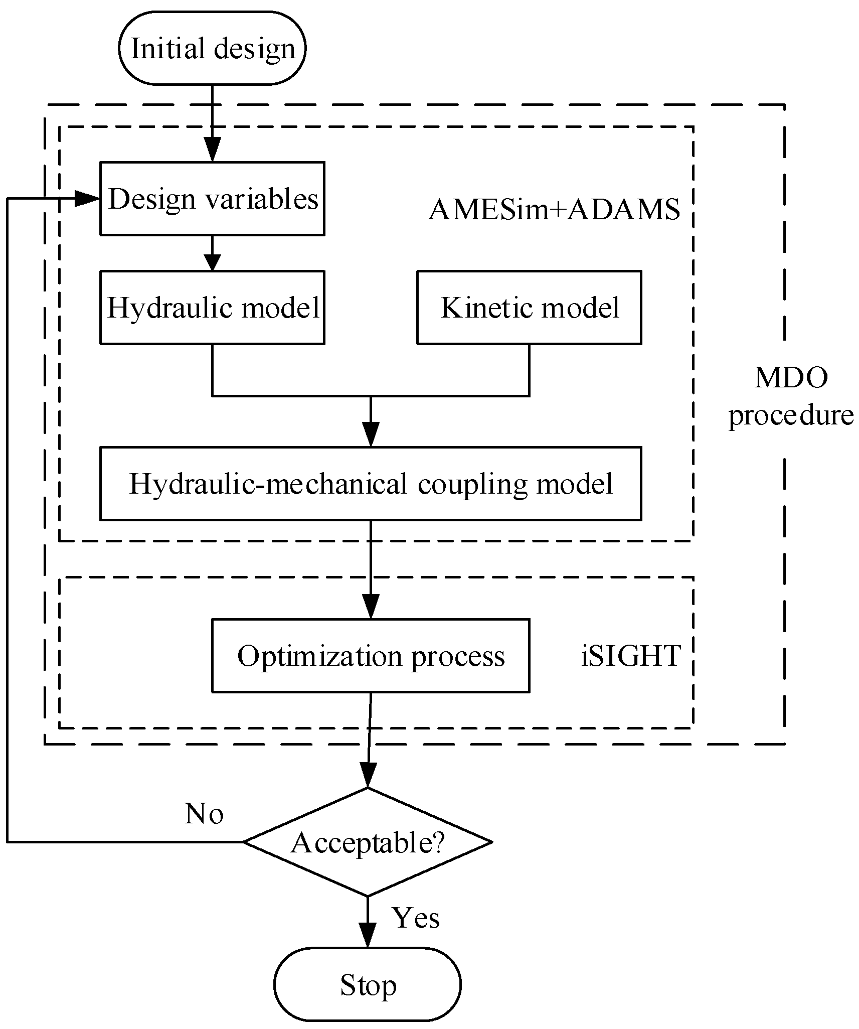
4.1. MDO Procedure

The MDO software iSIGHT (version 5.5, DS SIMULIA, Paris, France) is employed to optimize the pump. The hydraulic-mechanical coupling model can be integrated to form a design optimization framework. The MDO procedure for the pump is shown in Figure 6. AMESim is employed to define the hydraulic model, while the kinetic model is defined by ADAMS. iSIGHT integrates and runs the co-simulation program of AMESim and ADAMS through the AMEPilot tool, which is used to execute co-simulation program in other software environments. The objective function can be solved by reading input file and calculating design variables.
The parameters related to fluid distribution process are selected as design variables, including the wrap angle of the piston chamber, area of the suction port and delivery port, wrap angle of the silencing groove, and opening degree of the silencing groove, as shown in Table 2.
Considering the multi-load conditions, a multi-objective optimization is performed. Six flow ripple rates δ 20 , δ 24 , δ 28 , δ 32 , δ 36 and δ 40 are considered as optimization objectives in load conditions 20–40 MPa, at the interval of 4 MPa. The objective function is:
Min i n δ i = Min i n ( Q i max Q i min ) / Q i ave ( i = 20 ,   24 ,   28 ,   32 ,   36 ,   40 )

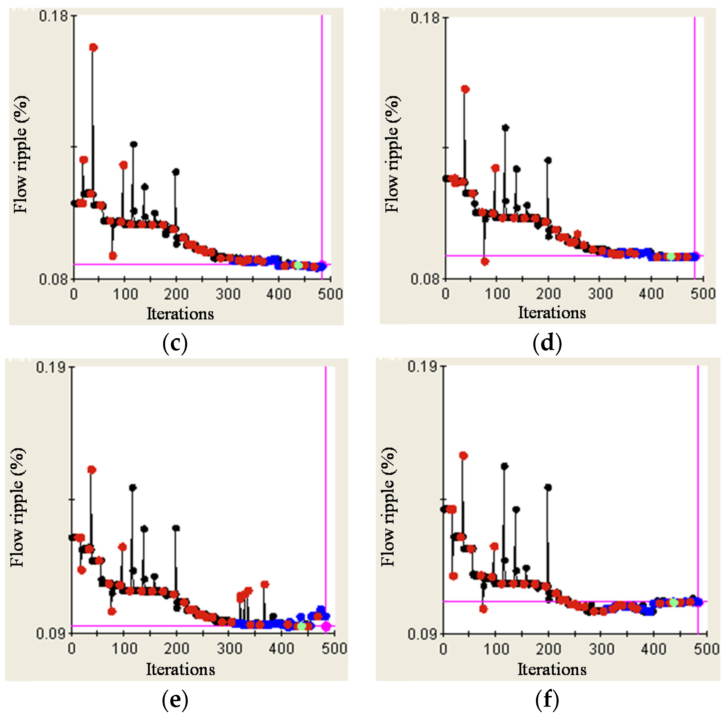
4.2. Integrated Optimization

Sequential Quadratic Programming (SQP), which has good convergence, high precision and good stability, is used to solve the multi-objective optimization. The optimal solution of the objective function is found after 480 iterations. The optimization processes of the flow ripple are shown in Figure 7.
The pump models before and after optimization are run in a co-simulation system, and the flow characteristic curves of the pump are shown in Figure 8.
It is seen that the flow ripple rates have decreased markedly after optimization. Figure 9 shows the comparison of the flow ripple rates before and after optimization. The maximum reducing rate is 25%, which occurs in the load condition of 40 MPa, and the minimum reducing rate is 14.5%, which occurs in the load condition of 20 MPa.

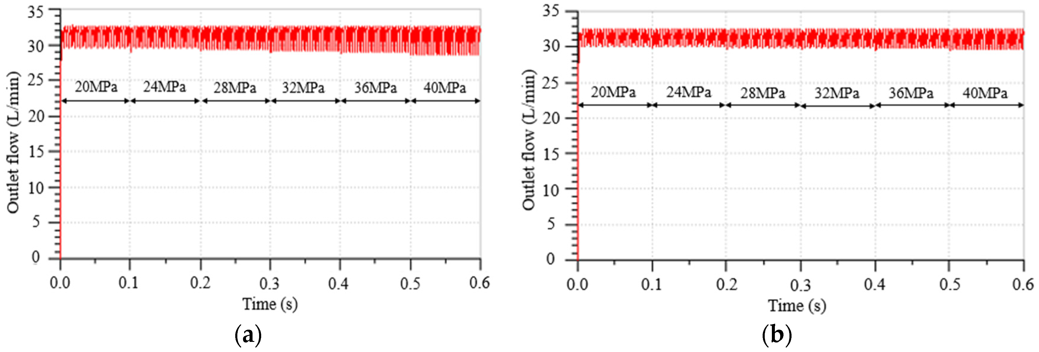
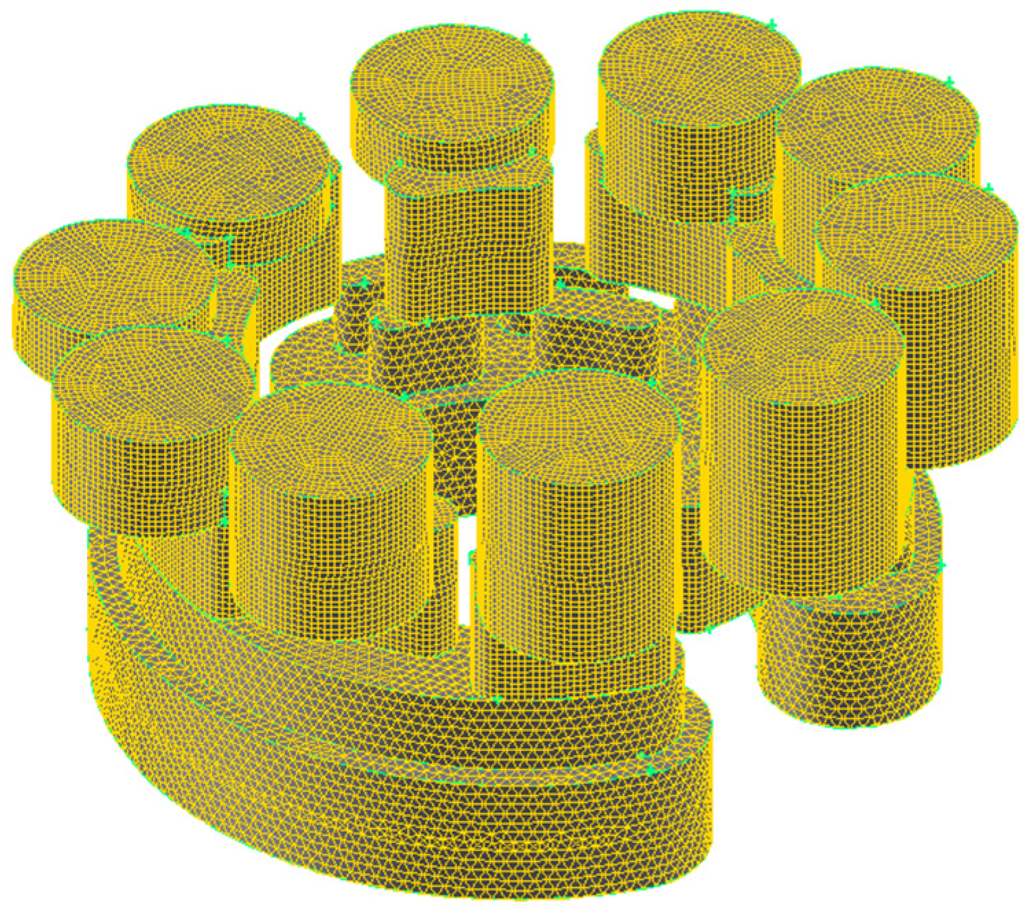
5. Numerical Simulation of Flow Field for the Optimized Pump

The flow fields of the piston pump before and after optimization are simulated using the CFD (Computational Fluid Dynamics) method. According to CFD theory, the state of flow fields can be depicted using the continuity equation, momentum conservation equation and energy conservation equation [18,19], and it is assumed that the properties of oil are viscous and compressible, and the form of flow is 3D transient and turbulent.
The internal flow field models before and after optimization are exported and meshed. Piston chambers are meshed using the Hex method while valve fields are meshed with the Tex/Hybrid method, and the local grids in leakage zones of grooves are refined so that high-quality grids can be obtained. The total number of grid cells is 280,463. The flow is simulated as turbulent, and the k-epsilon model is used in the simulation, as shown in Figure 10.
The relative rotation of pistons and valve plate is achieved by sliding grid, the rotary area is defined to moving mesh and the rotational speed is 105 r/s. The type of boundary condition is defined to pressure boundary. The inlet pressure is 0.2 MPa, and the outlet pressure is 20 MPa. In the CFD simulation, 40# hydraulic oil (SINOPEC, Beijing, China) is used, and its properties are shown in Table 3.
The pressure contours are shown in Figure 11. The values presented are obtained from the CFD simulation, and in Figure 11a, such values are approximately to be seen that the peak pressure in dead zone is up to 23.2–24.4 MPa, the pressure in delivery chambers is 19.5–20.8 MPa, and the pressure in suction chambers is 0.18–1.4 MPa before optimization. In Figure 11b, such values are about to be seen that the peak pressure in dead zone is 21.3–22.4 MPa, the pressure in delivery chambers is 19.0–20.1 MPa, and the pressure in suction chambers is 0.17–1.3 MPa after optimization. The results show that the hydrodynamic shock of the pump is obviously improved by optimization.

6. Experiment

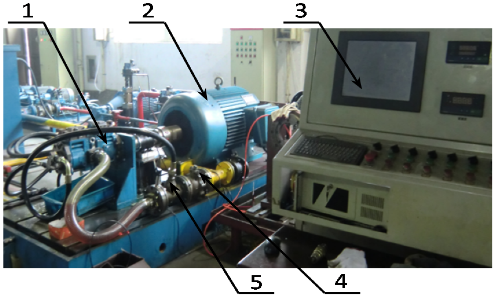
6.1. Experimental Setup

To verify the result of MDO of the pump, an experiment is performed, as shown in Figure 12. The experimental hydraulic circuit is shown in Figure 13, in which flowmeters (HuaKong, Beijing, China) are connected to the inlet and the outlet of the pump (INI hydraulic, Ningbo, China) to measure its working flow. The flowmeter LWGYA-15 (HuaKong, Beijing, China) is used in the experiment. Its measuring range is 0.4~8 m3/h, the precision grade is 0.5%, the repetitive error is about 0.05%~0.2%, and the max working frequency is 4 kHz, and the pressure gauge (HYDAC, Berlin, Germany) is connected to the outlet of the pump to measure the pressure. A relief valve is arranged at the outlet of the pump to ensure the safety of hydraulic circuit and provide appropriate pressure, and the pump is driven by motor (SIMO, Xi’an, China) through a torque meter (XYDC, Changsha, China).
The experiment is performed under the conditions that the spindle speed is 1500 r/min, the swashplate angle is 12.5°, and the load pressure is 20 MPa. The flow sensor and pressure sensor are used to collect flow and pressure data.

6.2. Results and Discussion

According to the experimental data, the comparison of outlet flow of the experiment and simulation after the optimization is shown in Figure 14. The comparison of outlet flow and outlet pressure before and after optimization are shown in Figure 15 and Figure 16, respectively.
Overall, the simulated and experimental curves are similar, and both the changing trend and the amplitude are basically consistent, as shown in Figure 14.
The flow ripple is smaller after the optimization design, and it is reduced by 1.72 L/min, as shown in Figure 15, which shows that the flow ripple can be improved by the MDO procedure.
In Figure 16, the peak of the pressure curve is lower after the optimization design; pressure pulsation is reduced by 0.21 MPa, which shows that the pressure pulsation is also improved with a decrease in the flow ripple.
By comparing the experimental and simulation results, it can be concluded that multidisciplinary design optimization is effective and feasible in the optimization design of the piston pump performance.

7. Conclusions

(1)
The co-simulation system for the pump is established, and a hydraulic-mechanical coupling analysis is realized. The hydraulic-mechanical coupling model is integrated to form a design optimization framework. The MDO procedure is employed to optimize the pump.
(2)
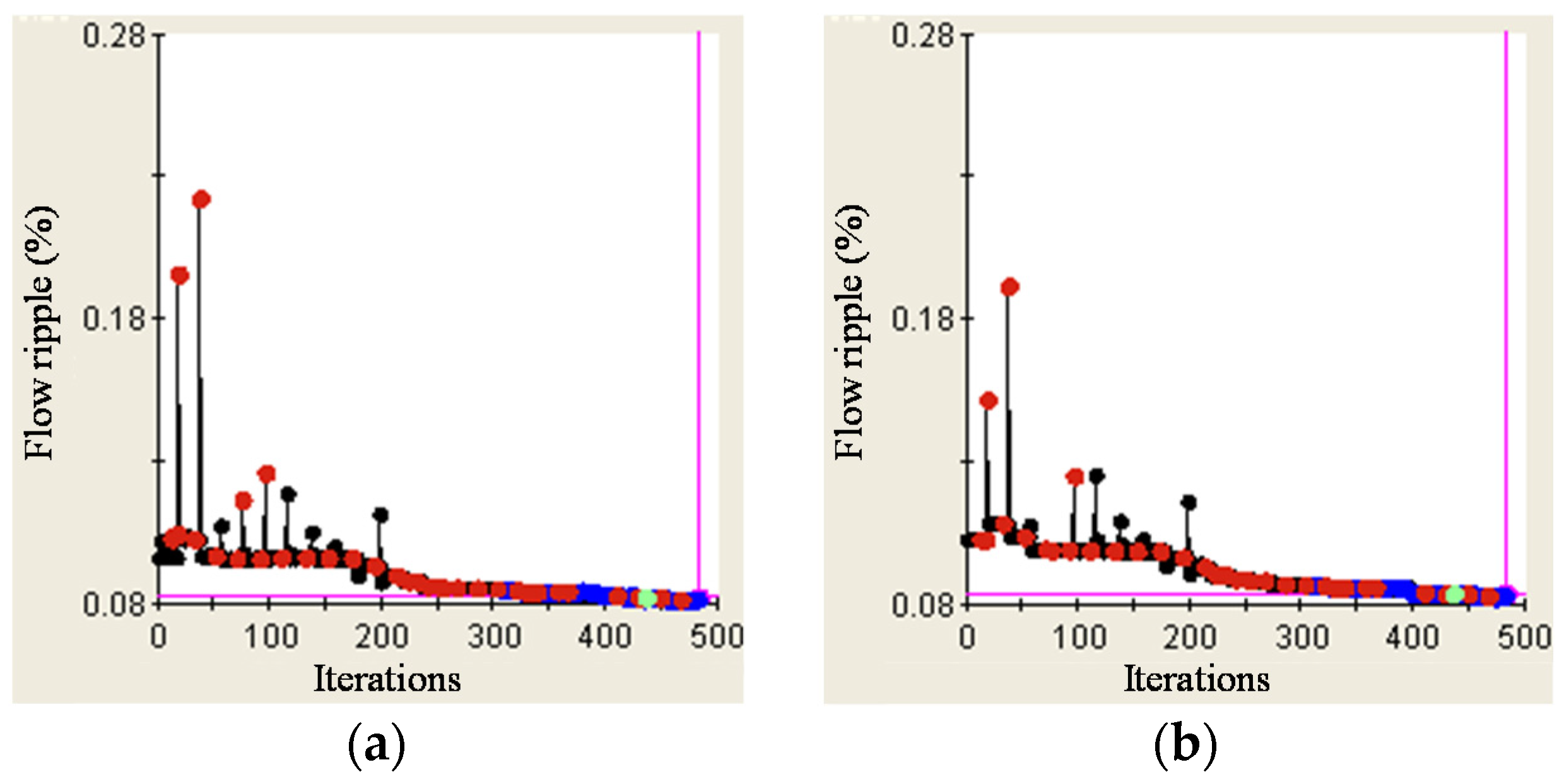
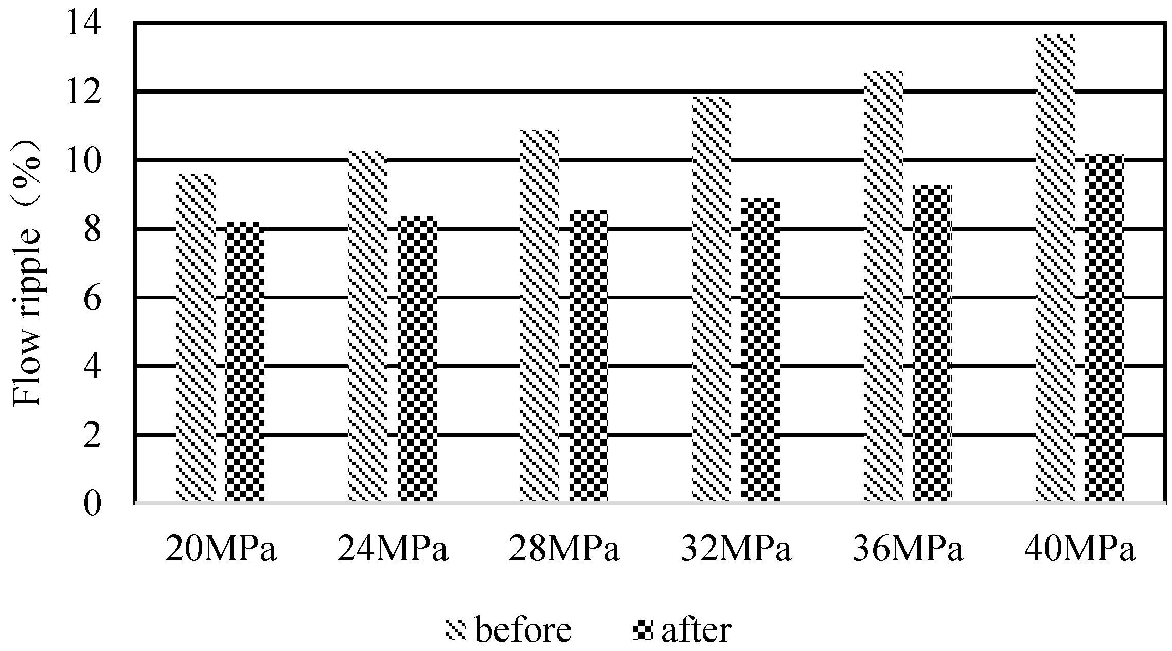
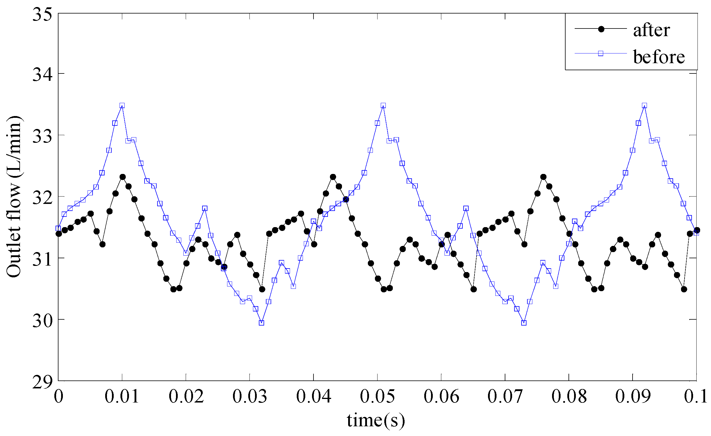
Through the integration and optimization, the flow ripple rates under six load conditions are improved. The maximum reducing rate is 25% in load conditions of 40 MPa, and the minimum reducing rate is 14.5% in load condition of 20 MPa.
(3)
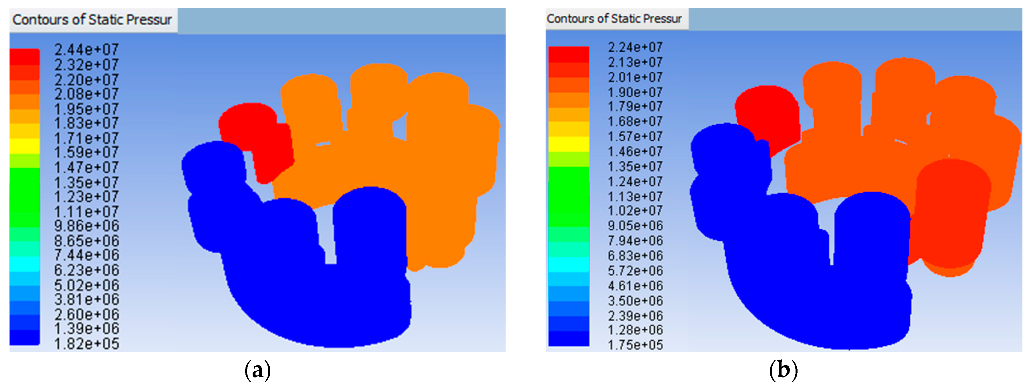
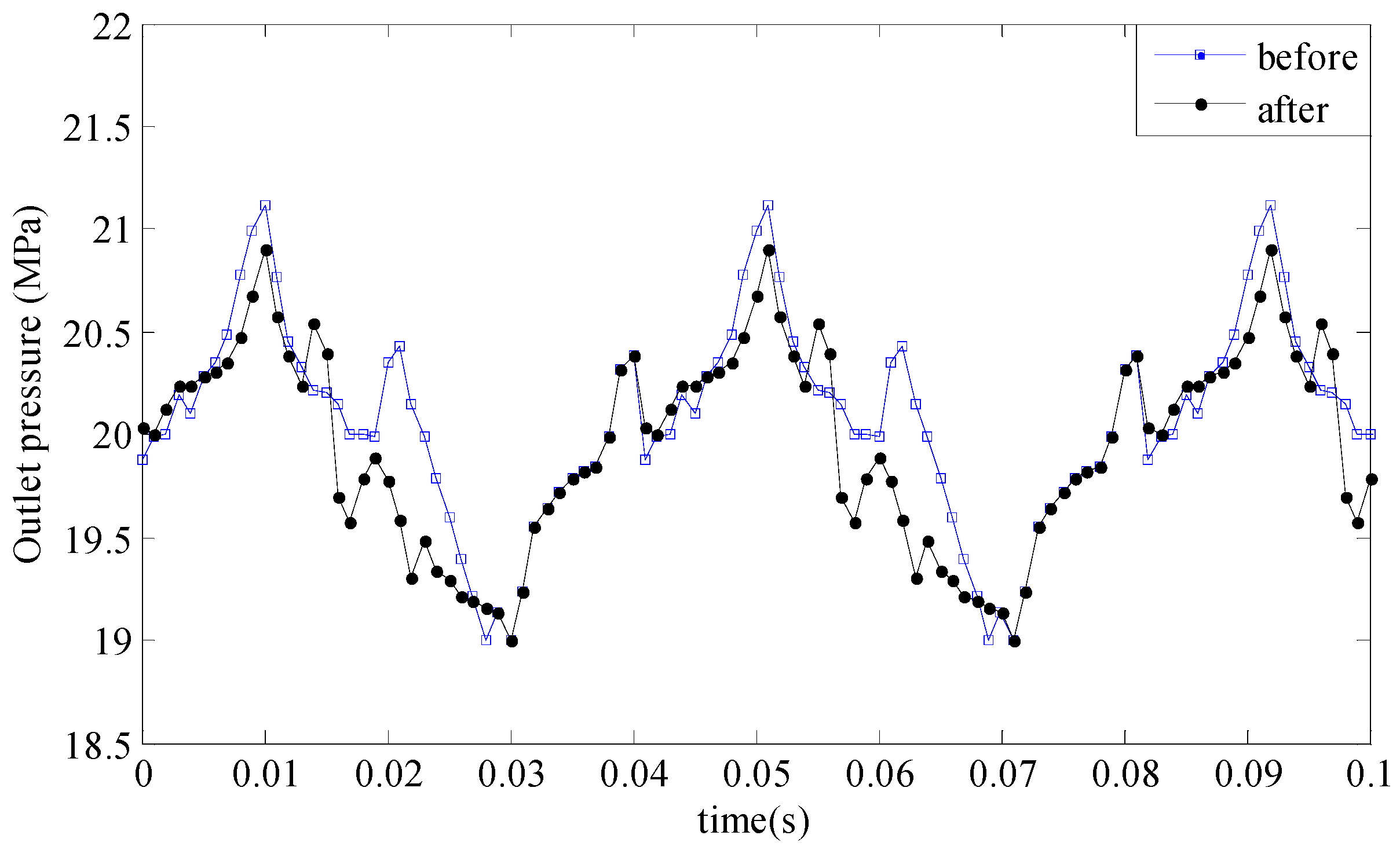
CFD simulation and experimental results show that the distribution of pressure is more uniform in flow field after optimization, which shows that the hydrodynamic shock of piston pump is obviously improved by optimization. It is indicated that the MDO procedure is effective and feasible in the design process for a piston pump.

Acknowledgments

The authors would like to acknowledge the support of the National Natural Science Foundation of China under Grant No. 51305049, the Fundamental Research Funds for the Central Universities, and the National Key Technology Support Program under Grant No. 2015BAF07B05.

Author Contributions

Guangjun Liu and Xiaofeng Wu designed and implemented the optimization procedure proposed in the paper. Zhaocheng Zhou and Xin Qian contributed with modeling and programming code as well as experiment. Weihai Pang analyzed the data.

Conflicts of Interest

The authors declare no conflict of interest.

References

  1. Montazeri, M.J.; Ebrahimi, R. Multidisciplinary optimization of a pump–fed system in a cryogenic LPE using a systematic approach based on genetic algorithm. Aerosp. Sci. Technol. 2016, 49, 185–196. [Google Scholar] [CrossRef]
  2. Cho, I.S.; Jung, J.Y. A study on the pressure ripple characteristics in a bent-axis type oil hydraulic piston pump. J. Mech. Sci. Technol. 2013, 27, 3713–3719. [Google Scholar] [CrossRef]
  3. Mikami, A.; Imoto, K.; Tanabe, T.; Niidome, T.; Mori, Y.; Takeshima, H.; Narumiya, S.; Numa, S. Geometric and kinematic modeling of a variable displacement hydraulic bent-axis piston pump. J. Comput. Nonlinear Dyn. 2010, 5, 2040–2049. [Google Scholar]
  4. Vasiliu, N.; Costin, I.; Călinoiu, C.; Vasiliu, D.; Bontos, M.D. Designing the Controller of a Servo Valve by Simulation. Stud. Inform. Control 2016, 25, 51–58. [Google Scholar]
  5. Wachutka, G. Coupled-field modeling of microdevices and microsystems. In Proceedings of the International Conference on Simulation of Semiconductor Processes and Devices, Kobe, Japan, 4–6 September 2002; pp. 9–14.
  6. Kim, J.H.; Jeon, C.S.; Hong, Y.S. Constant pressure control of a swash plate type axial piston pump by varying both volumetric displacement and shaft speed. Int. J. Precis. Eng. Manuf. 2015, 16, 2395–2401. [Google Scholar] [CrossRef]
  7. Xu, B.; Lee, K.M.; Song, Y.; Wang, Q.; Yang, H. A numerical and experimental investigation of parametric effect on flow ripple. Proc. Inst. Mech. Eng. Part C J. Mech. Eng. Sci. 2015, 229, 1989–1996. [Google Scholar] [CrossRef]
  8. Lee, J.K.; Jung, J.K.; Chai, J.B.; Jin, W.L. Mathematical modeling of reciprocating pump. J. Mech. Sci. Technol. 2015, 29, 3141–3151. [Google Scholar] [CrossRef]
  9. Cho, I.S. A study on the optimum design for the valve plate of a swash plate-type oil hydraulic piston pump. J. Mech. Sci. Technol. 2015, 29, 2409–2413. [Google Scholar] [CrossRef]
  10. Mandal, N.P.; Saha, R.; Mookherjee, S.; Sanyal, D. Pressure compensator design for a swash plate axial piston pump. J. Dyn. Syst. Meas. Control 2013, 136, 167–175. [Google Scholar] [CrossRef]
  11. Bae, J.H.; Chung, W.J.; Kim, S.B.; Jang, J.H. A study on pressure and flow pulsation of swash plate type variable piston pump through analysis of pulsation variables and valve plate notch design for automation of hydraulic system. In Proceedings of the IEEE International Conference on Mechatronics and Automation, Tianjin, China, 3–6 August 2014; pp. 418–423.
  12. Xue, G.S.; Lin, W.; Baek, S.H.; Park, Y.C. Multidisciplinary optimization of a butterfly valve. ISA Trans. 2009, 48, 370–377. [Google Scholar]
  13. Zhao, B.J.; Qiu, J.; Zhao, Y.F.; Zhang, C.H.; Chen, H.L. Multi-objective and multidisciplinary optimization of double-channel pump. Trans. Chin. Soc. Agric. Mach. 2015, 46, 96–101. [Google Scholar]
  14. Shi, L.J.; Tang, F.P.; Xie, R.S.; Qi, L.L.; Yang, Z.D. Design of axial flow pump modification and its effect based on CFD calculation. Nongye Gongcheng Xuebao/Trans. Chin. Soc. Agric. Eng. 2015, 31, 97–102. [Google Scholar]
  15. He, Y.; Mcphee, J. Multidisciplinary design optimization of mechatronic vehicles with active suspensions. J. Sound Vib. 2005, 283, 217–241. [Google Scholar] [CrossRef]
  16. Jang, D.H.; Lee, S.K.; Kwon, J.H.; Park, S.H. A study on pressure, flow fluctuation and noise in the cylinder of swash plate type axial piston pump. Trans. Korea Fluid Power Syst. Soc. 2009, 6, 1–9. [Google Scholar]
  17. Choudhuri, K.; Chakraborty, S.; Chakraborti, P.; Dutta, P. Stress analysis and design optimization of piston, slipper assembly in an axial piston pump. J. Sci. Ind. Res. 2014, 73, 318–323. [Google Scholar]
  18. Ma, J.E.; Xu, B.; Zhang, B.; Yang, H.Y. Flow ripple of axial piston pump with computational fluid dynamic simulation using compressible hydraulic oil. Chin. J. Mech. Eng. 2010, 23, 45–52. [Google Scholar] [CrossRef]
  19. Xu, B.; Hu, M.; Zhang, J. Impact of typical steady-state conditions and transient conditions on flow ripple and its test accuracy for axial piston pump. Chin. J. Mech. Eng. 2015, 28, 1012–1022. [Google Scholar] [CrossRef]
  20. Singh, R.R.; Nataraj, M. Analysis and optimization of pump performance variables using genetic algorithm and taguchi quality concept: A case study. Parasitol. Res. 2016, 115, 1529–1536. [Google Scholar]
  21. Kim, J.; Yoon, G.H.; Noh, J.; Lee, J.; Kim, K.; Park, H.; Hwang, Y.; Lee, Y. Development of optimal diaphragm-based pulsation damper structure for high-pressure GDI pump systems through design of experiments. Mechatronics 2013, 23, 369–380. [Google Scholar] [CrossRef]
  22. Mao, Y.; Zeng, L.; Lu, Y. Modeling and optimization of cavitation on a textured cylinder surface coupled with the wedge effect. Tribol. Int. 2016, 104, 212–224. [Google Scholar] [CrossRef]
  23. Wang, G.R.; Chu, F.; Tao, S.Y.; Jiang, L.; Zhu, H. Optimization design for throttle valve of managed pressure drilling based on CFD erosion simulation and response surface methodology. Wear 2015, 338–339, 114–121. [Google Scholar] [CrossRef]
Figure 1. The swash-plate axial piston pump: (1) Swash plate; (2) Pistons; (3) Connecting rod; (4) Shell; (5) Variable displacement mechanism; (6) Valve plate; (7) Cylinder; (8) Slipper; (9) Slipper retainer; (10) Spindle.
Applsci 06 00399 g001
Figure 2. Piston motion.
Applsci 06 00399 g002
Figure 3. Dynamic model of the pump.
Applsci 06 00399 g003
Figure 4. Data exchange.
Applsci 06 00399 g004
Figure 5. Results of co-simulation: (a) Outlet flow; (b) Outlet pressure; (c) Piston force.
Applsci 06 00399 g005
Figure 6. MDO procedure for the pump.
Applsci 06 00399 g006
Figure 7. Iteration process of flow ripple: (a) 20 MPa; (b) 24 MPa; (c) 28 MPa; (d) 32 MPa; (e) 36 MPa; (f) 40 MPa.
Applsci 06 00399 g007aApplsci 06 00399 g007b
Figure 8. Flow characteristic curves of the pump: (a) Before optimization; (b) After optimization.
Applsci 06 00399 g008
Figure 9. Comparison of flow ripple.
Applsci 06 00399 g009
Figure 10. Mesh of the flow field.
Applsci 06 00399 g010
Figure 11. Pressure contours: (a) Before optimization; (b) After optimization.
Applsci 06 00399 g011
Figure 12. Experimental set-up: (1) Pump; (2) Motor; (3) Data acquisition machine; (4) Flow sensor; (5) Relief valve.
Applsci 06 00399 g012
Figure 13. Experimental hydraulic circuit.
Applsci 06 00399 g013
Figure 14. Comparison of the outlet flow of the experiment and simulation after optimization.
Applsci 06 00399 g014
Figure 15. Comparison of outlet flow in the experiment before and after the optimization design.
Applsci 06 00399 g015
Figure 16. Comparison of outlet pressure in the experiment before and after the optimization design.
Applsci 06 00399 g016
Table 1. Simulation parameters.
ParameterValue
Piston’s diameter14.5 mm
Radial clearance of piston0.02 mm
Working pressure30 MPa
Swash-plate angle12.5°
Radius of pistons distribution circle29 mm
Spindle speed1500 r/min
Table 2. Design variables.
Design VariablesDescriptionConstraints
x 1 Wrap angle of piston chamber (°) 20 x 1 50
x 2 Equivalent diameter of suction port (mm) 2 x 2 14 . 5
x 3 Equivalent diameter of delivery port (mm) 2 x 3 14 . 5
x 4 Wrap angle of silencing groove in inlet zone (°) 0 x 4 50
x 5 Wrap angle of silencing groove in outlet zone (°) 0 x 5 50
x 6 Opening degree of silencing groove in inlet zone 0 x 6 0 . 06
x 7 Opening degree of silencing groove in outlet zone 0 x 7 0 . 06
Table 3. Material’s properties.
ParameterValue
Density ( kg / m 3 )889
Viscosity ( Pa s )0.048
Thermal conductivity ( W m 1 K 1 )0.0264
Specific heat ( J kg 1 K 1 )1006

