
The Development of Piezo-Driven Tools for Cellular Piercing

1
Jiangsu Provincial Key Laboratory of Advanced Robotics, Soochow University, Suzhou 215021, China
2
Collaborative Innovation Center of Suzhou Nano Science and Technology, Soochow University, Suzhou 215021, China
3
Institute of Clinical Immunology, The First Affiliated Hospital of Soochow University, Suzhou 215006, China
4
Jiangsu Province Key Laboratory of Stem Cell Research, Soochow University, Suzhou 215006, China
*
Author to whom correspondence should be addressed.
Appl. Sci. 2016, 6(11), 314; https://doi.org/10.3390/app6110314
Submission received: 21 August 2016
/
Revised: 26 September 2016
/
Accepted: 17 October 2016
/
Published: 26 October 2016
(This article belongs to the Special Issue Biomedical Ultrasound)
Abstract
:Conventionally, intracytoplasmic sperm injection (ICSI) in the mouse is conducted with piezo-drills that use a droplet of mercury for damping. The use of mercury causes concerns of toxicity and contamination. Although Fluorinert can be used as a substitute for mercury to reduce piezo-drill’s lateral vibration, the damping effect is not as satisfactory as mercury. In this work, a modified piezo-drill without using mercury was developed for the cellular piercing of mouse oocytes. Experimentally, appropriate parameters of driving voltage and frequency were obtained for the penetration of the zona pellucida of mouse oocytes. Furthermore, the lateral vibration of the injection pipette is lower than 1 μm in deionized water, which is not observable at 400 magnificence. With the piezo-drill without using mercury, the system performs the cellular piercing of mouse oocytes with a maximum cleavage rate of 94.7% (n = 117).
1. Introduction
Intracytoplasmic sperm injection (ICSI) is routinely used in the treatment of male infertility [1,2,3], husbandry such as in cows [4], and transgenic research using mice [5,6,7,8]. To realize ICSI, many techniques have been developed such as conventional ICSI [2,9,10], piezo-assisted ICSI [4,11,12], and the Ros-drill technique [13]. Conventional ICSI is commonly implemented in humans and domestic animals where the rupture of the oolemma is achieved by largely deforming the oocyte. In order to penetrate the zona pellucida without significantly deforming the oocyte, piezo-driven ICSI and the Ros-drill technique were developed. In the Ros-drill technique, the tip of the injection pipette is rotationally oscillated [13]. This technique produces a cleavage rate of approximately 70% in mouse oocytes. However, due to the eccentricity of pipettes from manufacturing, the pipette tip has a whirling motion resulting in undesirable lateral displacements, which causes damage to the oocyte membrane.
In piezo-drilling, a small droplet of mercury is necessary for successful mouse ICSI [5]. Piezo-drilling employs impulsive signals to drive the injection pipette tip with precise and prompt motions. The use of mercury reduces the lateral oscillations of the injection pipette [14], without which piezo-drilling produces a low cleavage rate and a large lateral vibration. However, mercury causes concerns of toxicity and contamination to the manipulated oocytes [15,16,17]. Although FC-77 can be used as a substitute for mercury, its damping effect is not as satisfactory as mercury [9]. To avoid using mercury, a piezo-driven technique was reported for the puncture of zebrafish embryos [18]. The piezo-drill design produces large lateral vibrations and is not suitable for piercing mouse oocytes that are at least 10 times smaller than zebrafish embryos. In addition, this technology utilizes a high frequency that may result in the agitation of the cytoplasm.
Thus, the objective of this work was to develop new piezo-driven tools for piercing mouse oocytes with low lateral vibration magnitudes and without using mercury. This was achieved by two modified injectors. The first modified injector was developed by placing the piezoelectric actuator close to the injection pipette tip. The second modified injector was constructed by designing accessories to combine the injection pipette holder and piezoelectric actuator using friction force instead of a screw joint. Experimental results demonstrate that the piezo-driven tool produced low deformation on mouse oocytes and was efficient in penetrating the zona pellucida.
2. Materials and Methods
2.1. Preparation of Mouse Oocytes
The mouse oocytes were achieved from the oviducts of B6C3F1 female mice (Shanghai SLAC Laboratory Animal Co., Ltd., Shanghai, China), 6–8 weeks old, conforming to the national relevant regulations of experimental animals. The superovulation of mice was induced by intraperitoneal (i.p.) injection of 10 IU Pregnant Mare Serum Gonadotropin (PMSG, Ningbo Second Hormone Factory, Ningbo, China) for 48 h followed by 10 IU Human Chorionic Gonadotropin (HCG, Ningbo Second Hormone Factory, Ningbo, China). The oviducts of the mice were excised about 16 h after HCG injection. The oocytes were then incubated at 37 °C with 5% CO2 [5].
2.2. Preparation of Pipettes
Holding pipettes, with an inner diameter of ~15 μm and an outer diameter of ~100 μm, were purchased from Eppendorf. The inner diameter of the injection pipettes was custom-made to be 8 μm, and the outer diameter was chosen to be 10 μm. The injection pipettes were prepared with the borosilicate glass capillary tubes (1.0 mm o.d., 0.75 mm i.d., Sutter Instrument, Novato, CA, USA), which were pulled by a micropipette puller (PM-1000; Sutter Instrument, Novato, CA, USA). Flat-ended injection pipettes were generated from the pulled capillaries with the assistance of a microforge (MF-900; NARISHIGE, Tokyo, Japan).
2.3. System Design
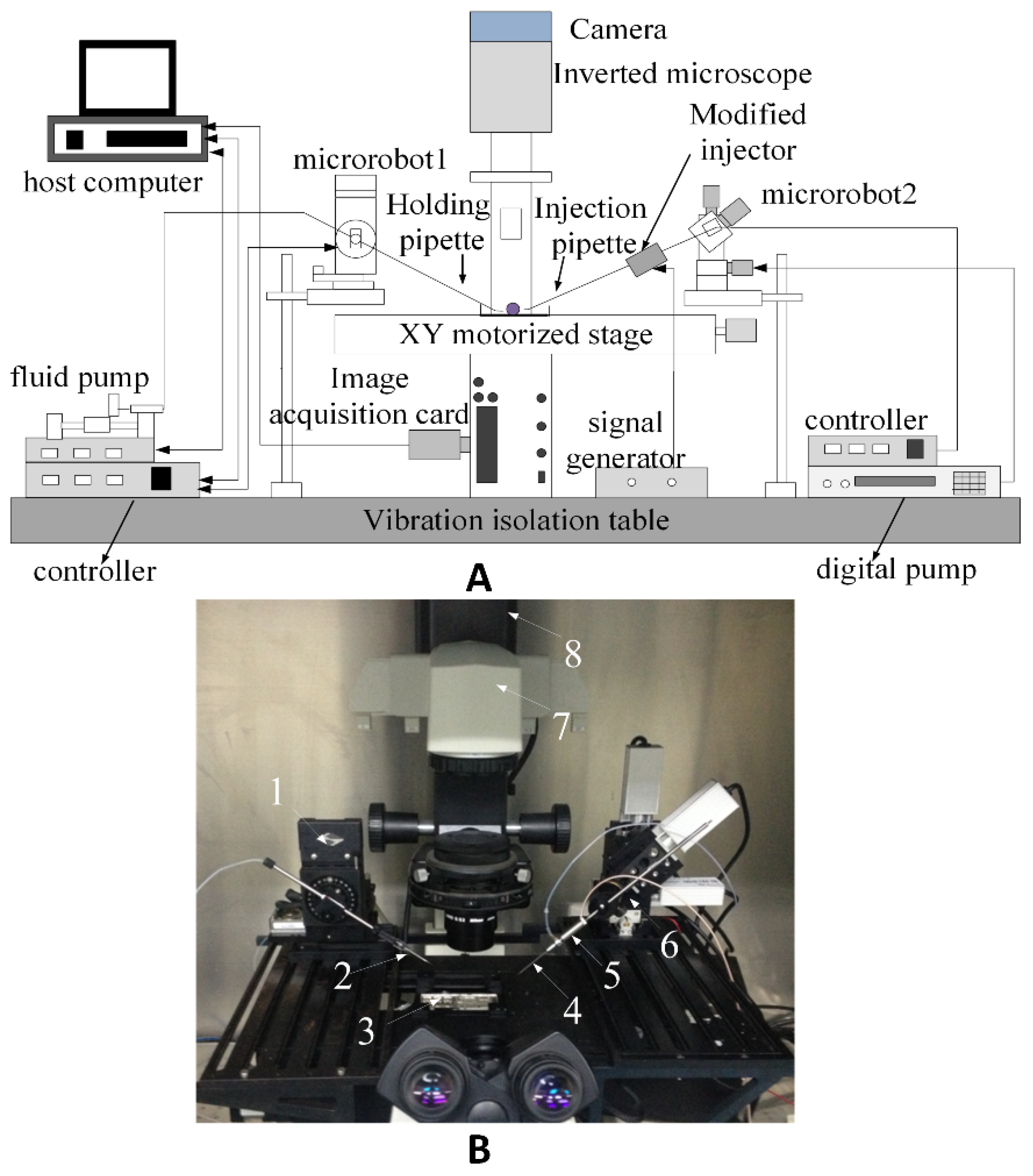
The system, as shown in Figure 1, consists of three parts, including an injection part, an imaging part, and a pressure system. The injection part employs an injection pipette, a holding pipette, a piezoelectric actuator, two pipette holders for clamping the holding pipette and piezoelectric actuator, respectively, and two motorized micromanipulators. The left micromanipulator (MP285, Sutter Instrument, Novato, CA, USA) has a travel distance of 25 mm with three axis motion and a positioning accuracy of 0.04 μm along each axis. The right micromanipulator (MX7600R; Siskiyou Design Instrument, Washington, DC, USA) has a travel distance of 20 mm with four axis motion and a step resolution of 0.04 μm along each axis. An imaging part involves a Charged Coupled Device (CCD) (A601F, Basler, Ahrensburg, Germany) mounted on an inverted microscope (Nikon, Tokyo, Japan). The pressure system includes a microfluid pump (Harvard Apparatus, Holliston, MA, USA) and a digital pump (Sutter Instrument, Novato, CA, USA). The microfluid pump was used to provide negative pressure to immobilize mouse oocytes. The digital pump was used to generate negative and positive pressure to promote the cytoplasm rupture of the oocytes. All equipment was placed on a vibration isolation table.
2.4. Design of the Piezo-Drill
The vibration of a conventional injector is approximately 37 μm and 270 μm in the deionized water and air, respectively, even with the assistance of mercury [19]. In the conventional injector, the piezoelectric actuator is placed behind the holder (Figure 2A). Taking into consideration the inner diameter, outer diameter, and the extent of the pulled section, the pulled section of the injection pipette can be modeled as a flexible beam [19]. This section is connected to the injection pipette’s shoulder, which has a high rigidity. Thus, the conventional injector, except the drawn section, is rigid, and the pulled section is connected to the rigid base.
Installation errors from the front of the piezoelectric actuator generate a slight deviation, θ. Axial force F is produced by the piezo-pulse, as shown in Figure 2B. We analyze the conventional injector in terms of the lateral vibration and kinetic energy. Here, a periodic driving signal is applied to the piezoelectric actuator, and the value of signal is positive. Displacement of the injection pipette generated from piezoelectric actuators is also periodic. When the pipette is placed against an oocyte, the indention force to the oocyte is linear to the displacement of the piezoelectric actuator [20], and the proportionality coefficient is defined as k. In addition, axial output force (F) of the piezoelectric actuator is equal to the indention force, which indicates that the axial output force is also periodic. Due to the existence of the installation error, a periodic point force Fy, inducing lateral vibrations of the injection pipette, is derived from the axial output force F.
where dmax represents the maximum displacement of the piezoelectric actuator when the maximum voltage Vmax is applied to the piezoelectric actuator, and g(t) is a periodic signal applied to the piezoelectric actuator.
Figure 3 shows a coordinate system for the pulled section of the injection pipette. The bending vibration equation of the cantilever is
where is mass per unit length, A is the cross section area of the pulled section, E is the Young’s modulus of the structure of the drawn section, I is the bending moment of inertia, F is the axial force produced by the piezo-pulse, is the deviation generated by the error of installation, w is the deflection of injection pipette tip, and f(x,t) and m(x,t) are the external force and moment both derived from the Fy. Modal coordinate transform is given below:
where describes the form of vibration, and is a function of the time used to describe the motion of the pulled section. The initial condition of the cantilever is
According to the initial condition, we can conclude that
The generated external periodic point force at tip of the pulled section, the coordinate of which is defined as x = xl, is derived as
where .
where l is the length of the pulled section of the injection pipette, and a represents the distance between the front of the piezoelectric actuator and the tip of the pulled section of the injection pipette. The obtained modal force is
Thus, the lateral vibration of the pulled section of the injection pipette is
When r ≥ 3, and ; therefore, and have the same sign. Equation (7) can be changed to the following equation:
where and are always positive when r ≥ 3. When the value of distance a increases, will increase accordingly. If other parameters remain constant, the deflection of the injection pipette tip w will increase. In addition, when the deviation angle generated from the installation error increases, and other parameters remain constant, the deflection of the injection pipette tip w will increase.
Kinetic energy (T) of pipette’s pulled section is
Equation (7) can be changed to
As a single injection pipette, actuator, and voltage are used in different injectors, all parameters are identical in Equation (10) except distance a and deviation angle . Because the pulled pipette is recognized as a cantilever, and have the same sign, and is also positive when r ≥ 3. When a becomes smaller, will become smaller, which will lead to a smaller kinetic energy T. In addition, when the deviation angle generated from the installation error decreases, kinetic energy T will decrease. If the pipette’s kinetic energy from the lateral vibration increases, more energy is required, further complicating the driving circuit.
According to the analysis mentioned above, decreasing the distance a and deviation angle is beneficial not only to the cellular piercing, but also for the simplification of the driving circuit. Here, we introduce two modified injectors where we change the distance a and deviation angle , respectively.
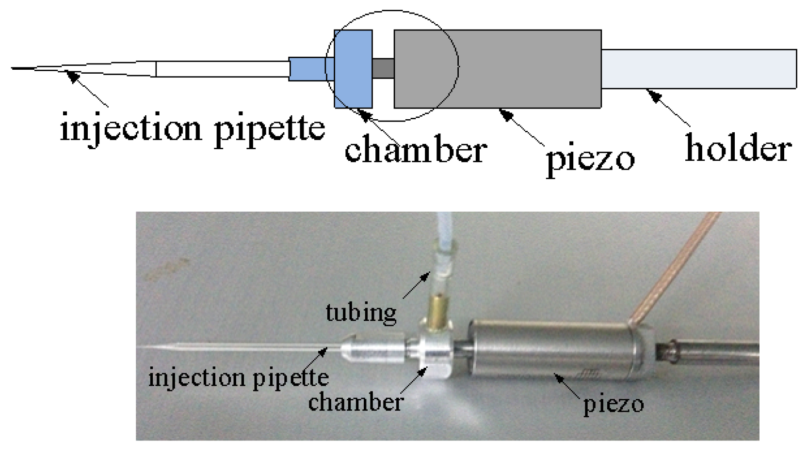
The analysis above reveals that, in order to reduce the lateral vibration of the pulled section of the injection pipette and to avoid wasting energy, distance a needs to be smaller. Hence, we placed the piezoelectric actuator closer to the injection pipette, while other parameters remained the same as the conventional injectors. Figure 4 shows the modified injector designed to reduce the lateral vibration of the injection pipette. In this modified injector, the front of the piezoelectric actuator is linked to a compact chamber rather than a long holder in the conventional injector.
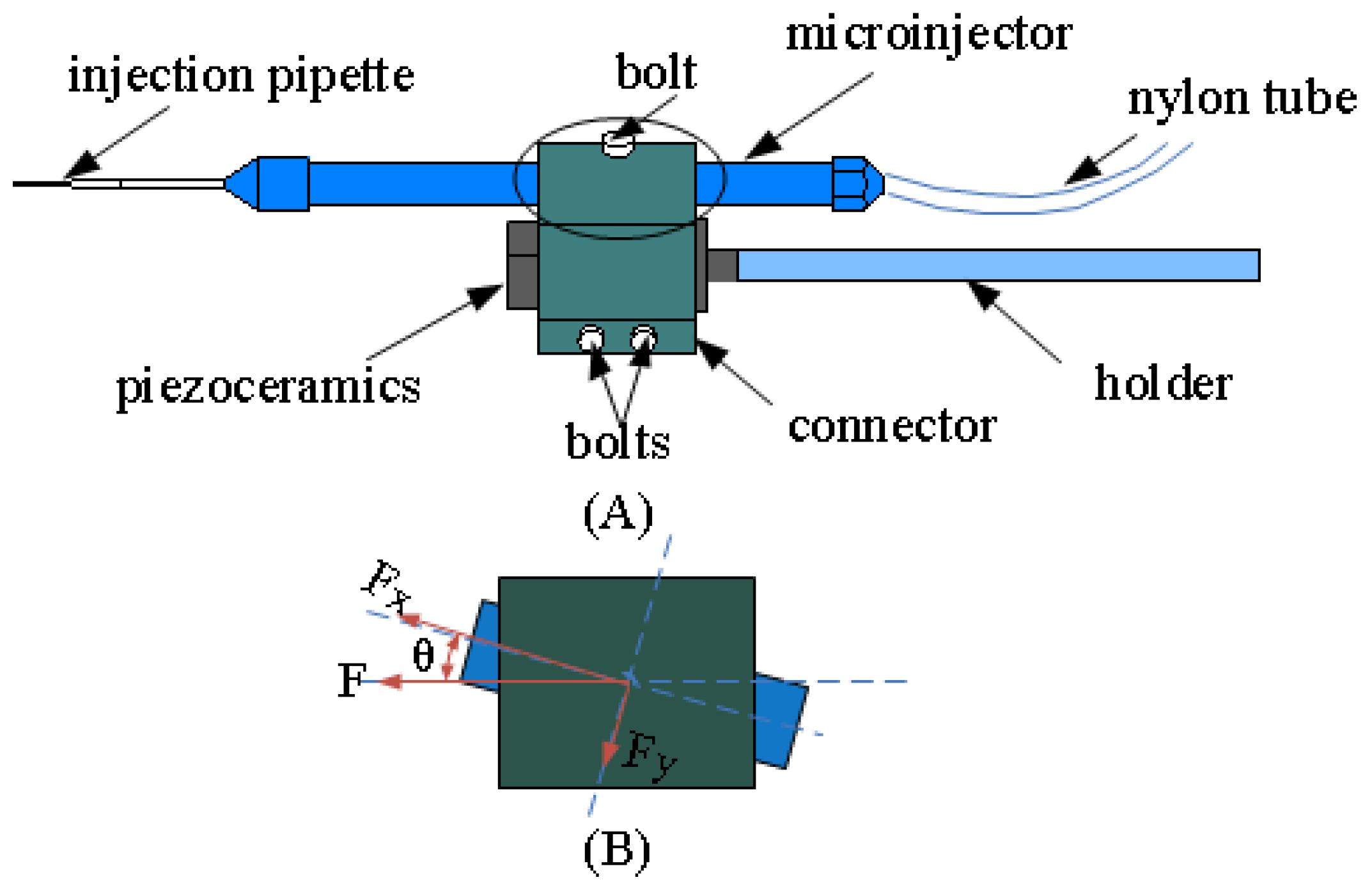
In addition, we restricted the deviation angle to be smaller; correspondingly, the external force in Equation (6a) became smaller. Thus, we developed another modified injector to reduce the lateral vibration. As shown in Figure 5, the piezoelectric actuator and the microinjector are linked together by the connector with the help of friction force. The motion of the piezoelectric actuator is transferred to the injection pipette by the friction force between the connector, the piezoelectric actuator, and the microinjector. Through the adjustment of bolts, the friction force can be adjusted.
In the conventional injector, the piezoelectric actuator is installed behind the chamber (Figure 2A). An installation error, which is presented in Figure 2B, is induced by the joint screw which is used to link the piezoelectric actuator and chamber. In addition, due to the existence of thread clearance, the concentricity of piezoelectric actuator and injection pipette cannot be guaranteed. This installation error can reach the millimeter scale which means the deflection angle , shown in Figure 2B, is rather large. In our injector design, the concentricity of the two cylindrical bores of the connector is restricted to the micrometer scale by precision machining. This concentricity tolerance of two cylindrical bores of the connector reduces the installation error significantly. The deflection angle shown in Figure 5B is far less than that shown in Figure 2B. The injection pipettes, piezoelectric actuators, and the driving signals applied to the actuators in this modified injector are the same as those in the conventional injector. Therefore, the parameters in the former equations remain identical except the deflection angle .
2.5. Procedure of Cellular Piercing
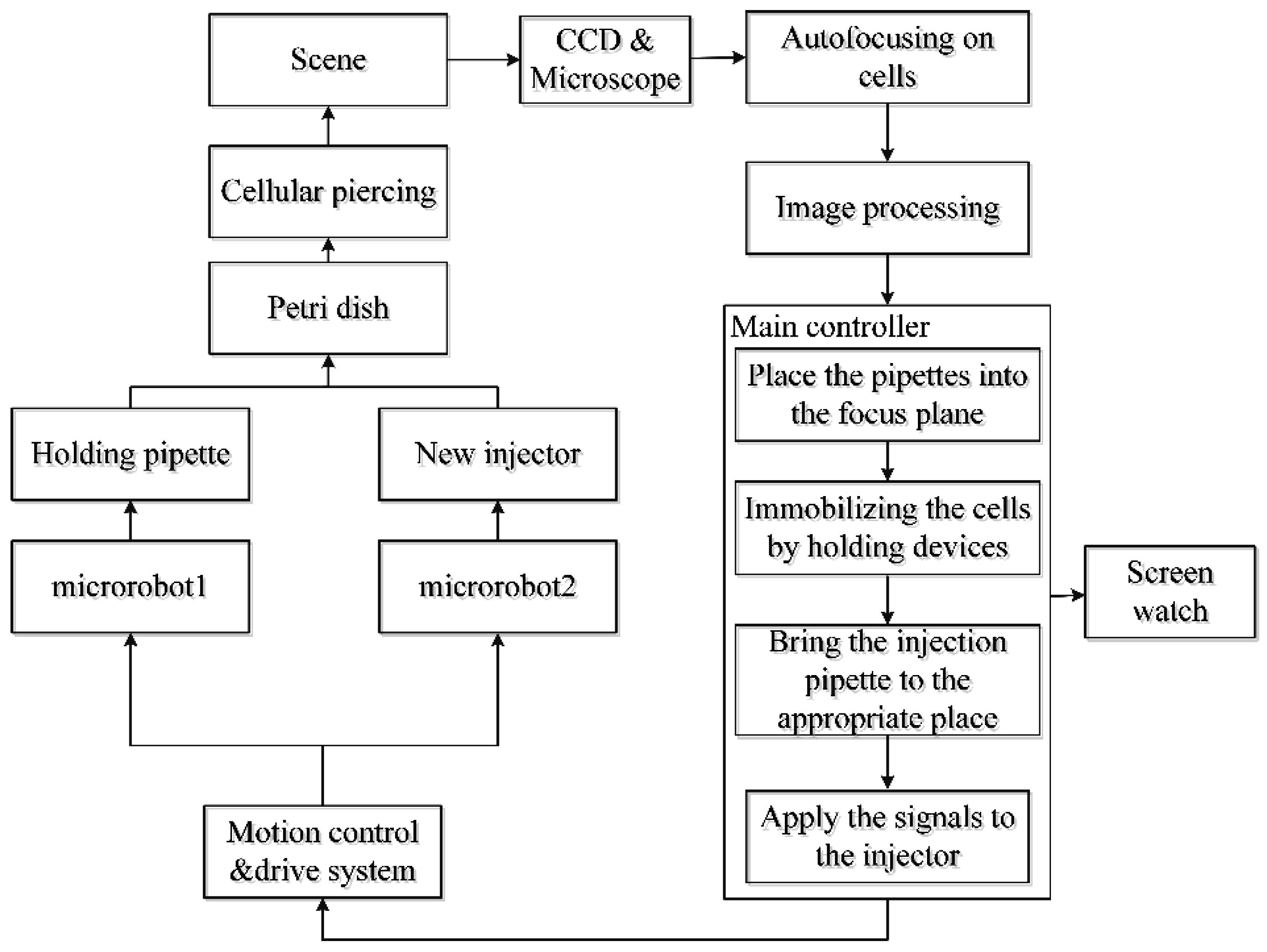
Before cellular piercing, optimal parameters of driving signals used to actuate the piezoelectric actuators should be achieved. The detailed description of the cellular piercing is shown in Figure 6.
3. Results and Discussion
In experiments, the temperature was maintained at 25 °C. To demonstrate the validity of our two modified injectors, a series of experiments were performed. Three measures were defined. (1) Lateral vibration: This measure is defined as the difference between the entire lateral oscillation of the injection pipette tip and the outer diameter of the injection pipette tip. Less lateral vibration causes less damage to mouse oocytes. (2) Cleavage rate: This measure is defined as the ratio between the number of oocytes pierced successfully and the total number of oocytes. (3) Stability: This measure is defined as the statistical analysis on different cleavage rates gained from a series of experiments with optimal parameters, which represents the reproducibility and stability of the modified injectors. Since structures of the membrane and zona pellucida are different, the voltages applied to pierce the membrane and zona pellucida was 30 V and 75 V, respectively. For both modified injectors, the lateral vibration strongly stirred the cytoplasm of the cells after puncturing the mouse oocytes when the frequencies were higher than 120 Hz.
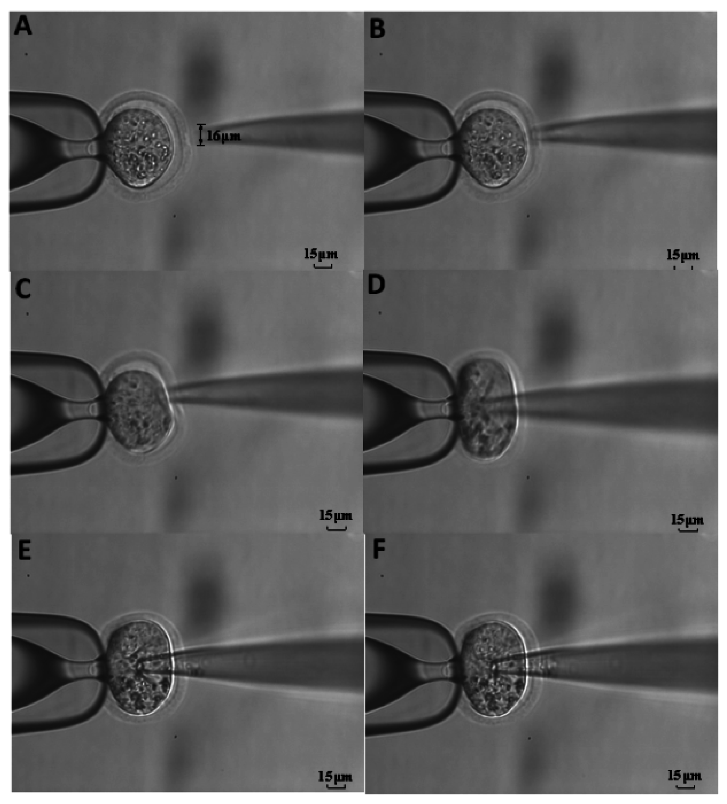
For the first modified injector where only the distance between the front of the piezoelectric actuator and the back of the pulled section of the injection pipette was shortened, we found that 60 Hz was effective in reducing the lateral vibration to 6 μm. The parameters of cellular piercing were U1 = 75 V and f1 = 60 Hz for the rupture of the zona pellucida and U2 = 30 V and f2 = 60 Hz for the rupture of the oocyte membrane, shown in Figure 7. Table 1 shows that the achieved cleavage rate of oocytes varied from 76.9% to 84.2%. On average, 80.1% of the injected oocytes were cleaved. Standard deviation was calculated to be 2.73%, indicating a high cleavage rate was achieved.
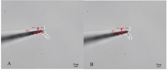
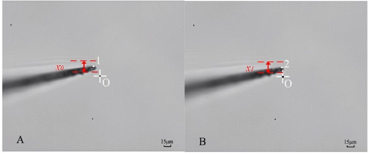
For the second modified injector where the injection pipette and piezoelectric actuator was combined by friction force instead of a screw joint, the reduction of the deflection angle is ensured. Experimentally, we found that the frequencies of 30 Hz and 45 Hz both led to the lateral vibration below 1 μm, which is invisible at 40× (objective) and 10× (eye-piece), shown in Figure 8. Each of the two frequencies was applied to pierce the membrane and zona pellucida on ten mouse oocytes with the same voltages mentioned above. As shown in Table 2, the frequency of 45 Hz was more effective for the rupture of the membrane and zona pellucida. To testify the validity of this frequency, more experiments were performed, and the results are summarized in Table 3. The cleavage rate varied from 88.0% to 94.7% with the average cleavage rate of 91.5%.
Two modified piezo-driven injectors were developed for the piercing of mouse oocytes. The novelty of the first modified injector is the more compact structure. The novelty of the second modified injector is in the connection of the injection pipette and the piezoelectric actuator. Both modified injectors outperform the conventional injector. The second modified injectors provide a smaller lateral vibration as low as 1 μm. Without the use of mercury, a high success rate of cellular piercing was obtained with both modified injectors. In both modified injectors, standard deviation was low, which means a high cleavage rate is reproducible.
A comparison of the two modified injectors reveals that the lateral vibration of the second modified injector is smaller than that of the first modified injector. This is attributed to the characteristics described in Equation (5a). Because the value of the deflection angle is small, a small change in this parameter can result in a large change of the external force f(t). However, a large change in the parameter a only leads to a small change of the external force f(t). In addition, the success rate of the cellular piercing in the first modified injector is less than that of the second modified injector. This can be attributed to the loss of energy. In the first modified injector, the loss of energy is larger than that of the second modified injector. Hence, the second modified injector requires less complicated driving circuits and is more effective for cellular piercing.
4. Conclusions
In this paper, we performed an analysis of conventional injector for cellular piercing. Based on this analysis, two modified injectors without using mercury were presented. Optimal parameters of applied driving signals were experimentally obtained to actuate modified injectors. Both modified injectors can provide smaller lateral vibrations than that of conventional injector. Lateral vibration of second modified injector is as low as 1 μm. When two modified injectors were used to perform the cellular piercing, high success rates of cellular piercing were achieved. Average success rate of the first modified injector was 80.1% and average success rate of the second modified injector was 91.5%. We achieved a lower success rate of the first modified injector than that of the second modified injector, which can be attributed to the larger loss of energy in the first modified injector. Therefore, second modified injector would be more effective for cellular piercing of mouse cells.
Acknowledgments
This work is financially supported by Instrument Development Major Program of National Nature Science of China (Grant No. 61327811), Marie Curie Actions-International Research Staff Exchange Scheme “Biomedical Robotics and Applications” (Grant No. PIRSES-GA-2013-612641), and Nanometer Technology Program of Science and Technology Development Plan of Suzhou (Grant No. ZXG201433).
Author Contributions
Conceived and designed the experiments: Changhai Ru, Peng Pan. Performed the experiments: Peng Pan, Changhai Ru. Analyzed the data: Peng Pan. Contributed reagents/materials/tools: Changhai Ru, Ruihua Chen. Wrote the paper: Peng Pan.
Conflicts of Interest
The authors have declared no conflicts of interest.
References
- Palermo, G.; Joris, H.; Devroey, P.; van Steirteghem, A.C. Pregnancies after intracytoplasmic injection of single spermatozoon into an oocyte. Lancet 1992, 340, 17–18. [Google Scholar] [CrossRef]
- Plachot, M.; Belaisch-Allart, J.; Mayenga, J.M.; Chouraqui, A.; Tesquier, L.; Serkine, A.M. Outcome of conventional IVF and ICSI on sibling oocytes in mild male factor infertility. Hum. Reprod. 2002, 17, 362–369. [Google Scholar] [CrossRef] [PubMed]
- Yanagida, K.; Katayose, H.; Yazawa, H.; Kimura, Y.; Konnai, K.; Sato, A. The usefulness of a piezo-micromanipulator in intracytoplasmic sperm injection in humans. Hum. Reprod. 1999, 4, 448–453. [Google Scholar] [CrossRef]
- Katayose, H.; Yanagida, K.; Shinoki, T.; Kawahara, T.; Horiuchi, T.; Sato, A. Efficient injection of bull spermatozoa into oocytes using a Piezo-driven pipette. Theriogenology 1999, 52, 1215–1224. [Google Scholar] [CrossRef]
- Kimura, Y.; Yanagimachi, R. Intracytoplasmic sperm injection in the mouse. Biol. Reprod. 1995, 52, 709–720. [Google Scholar] [CrossRef] [PubMed]
- Yanagimachi, R.; Wakayama, T. Development of normal mice from oocytes injected with freezes dried spermatozoa. Nat. Biotechnol. 1988, 16, 639–641. [Google Scholar]
- Dozortsev, D.; Wakaiama, T.; Ermilov, A.; Yanagimachi, R. Intracytoplasmic sperm injection in the rat. Zygote 1998, 6, 143–147. [Google Scholar] [CrossRef] [PubMed]
- Olsson, S.B.; Getahun, M.N.; Wicher, D.; Hansson, B.S. Piezo controlled microinjection: An in vivo complement for in vitro sensory studies in insects. J. Neurosci. Methods 2011, 201, 385–389. [Google Scholar] [CrossRef] [PubMed]
- Liu, J.; Lee, G.Y.; Lawitts, J.A.; Toner, M.; Biggers, J.D. Technical note: Mice produced by intracytoplasmic sperm injection using a modified conventional method. J. Anim. Sci. 2012, 90, 3739–3742. [Google Scholar] [CrossRef] [PubMed]
- Yoshida, N.; Perry, A.C. Piezo-actuated mouse intracytoplasmic sperm injection (ICSI). Nat. Protoc. 2007, 2, 296–304. [Google Scholar] [CrossRef] [PubMed]
- Markert, C.L. Fertilization of mammalian eggs by sperm injection. J. Exp. Zool. 1983, 228, 195–201. [Google Scholar] [CrossRef] [PubMed]
- Kawase, Y.; Iwata, T.; Watanabe, M.; Kamada, N.; Ueda, O.; Suzuki, H. Application of the piezo-micromanipulator for injection of embryonic stem cells into mouse blastocysts. J. Am. Assoc. Lab. Anim. Sci. 2001, 40, 31–34. [Google Scholar]
- Ergenc, A.F.; Olgac, N. New technology for cellur piercing: Rotationally oscilating u-injector, description and validation tests. Biomed. Microdevices 2007, 9, 885–891. [Google Scholar] [CrossRef] [PubMed]
- Ediz, K.; Olgac, N. Effect of the mercury column on the microdynamics of the piezo-driven pipettes. J. Biomech. Eng. 2005, 127, 531–535. [Google Scholar] [CrossRef] [PubMed]
- Gan, Y.; Chen, Z.; Montgomery-Smith, S. Improved material point method for simulating the zona failure response in piezo-assisted intracytoplasmic sperm injection. Comput. Model. Eng. Sci. 2011, 73, 45. [Google Scholar] [CrossRef]
- Huang, H.; Hao, S.; Chen, H.; James, K. Piezoelectric driven non-toxic injector for automated cell manipulation. In Proceedings of the Medicine Meets Virtual Reality Conference (MMVR), Laško, Slovenia, 14–15 April 2011; pp. 231–235.
- Liu, J.; Lee, G.; Lawitts, J.; Toner, M.; Biggers, J.D. Mice produced by ICSI using a conventional injection pipette without Piezo. Biol. Reprod. 2011, 85, 731. [Google Scholar]
- Huang, H.; Mills, J.K.; Sun, D. A new piezo-driven ultrasonic cell microinjection system. In Proceedings of the 2010 IEEE International Conference on Information and Automation (ICIA), Harbin, China, 20–23 June 2010; pp. 18–23.
- Ediz, K.; Olgac, N. Microdynamics of the piezo-driven pipettes in ICSI. IEEE Trans. Biomed. Eng. 2004, 51, 1262–1268. [Google Scholar] [CrossRef] [PubMed]
- Wan, K.T.; Chan, V.; Dillard, D.A. Constitutive equation for elastic indentation of a thin-walled bio-mimetic microcapsule by an atomic force microscope tip. Colloids Surf. B Biointerfaces 2003, 27, 241–248. [Google Scholar] [CrossRef]
Figure 1.
Mouse oocytes injection system. (A) Schematic diagram of the injection system architecture. (B) Part of the injection system: 1 is the microrobot-1, which is a three-degrees-of-freedom micromanipulator with a travel distance of 25 mm and a positioning accuracy of 0.04 μm along each axis; 2 is the holding pipette which is used to immobilize the oocytes; 3 is the medium for placing the oocytes; 4 is the injection pipette for cellular piercing; 5 is the injector for cellular piercing; 6 is the microrobot-2, which is a three-degrees-of-freedom micromanipulator with a stroke of 20 mm and a step resolution of 0.04 μm along each axis; 7 is the microscope; 8 is the Charged Coupled Device (CCD). Visual feedback is gained by the microscope and CCD.

Figure 2.
(A) Structure of the conventional injector. (B) Partial enlarged detail of the junction where the front of the piezoelectric actuator is connected to the holders in the conventional injector and a slight deviation θ is generated from installation errors.
Figure 2.
(A) Structure of the conventional injector. (B) Partial enlarged detail of the junction where the front of the piezoelectric actuator is connected to the holders in the conventional injector and a slight deviation θ is generated from installation errors.
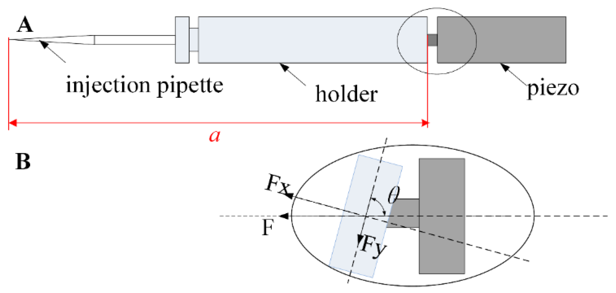
Figure 3.
Schematic of the pulled section of the injection pipette.
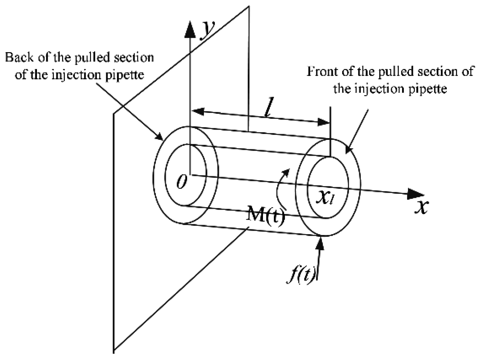
Figure 4.
Structure of the first modified injector.

Figure 5.
(A) Structure of the second modified injector. (B) Partial enlarged detail of the junction where the piezoelectric actuator is connected to the holders in the modified accessories.
Figure 5.
(A) Structure of the second modified injector. (B) Partial enlarged detail of the junction where the piezoelectric actuator is connected to the holders in the modified accessories.

Figure 6.
Cellular piercing flow chart.

Figure 7.
Directions of cellular piercing using the first modified injector. (A) Modulate the injection pipette close to the zona pellucida and ensure that vibration of pipette is small, about 6 μm. (B) Touch the zona pellucida. (C) Pierce through the zona pellucida. (D) Push the tip to the opposite side of the oocytes. (E) Pierce through the membrane of the oocytes. (F) Apply a gentle positive pressure to prevent the intensive suction of cytoplasm. Scale bars = 15 μm throughout.

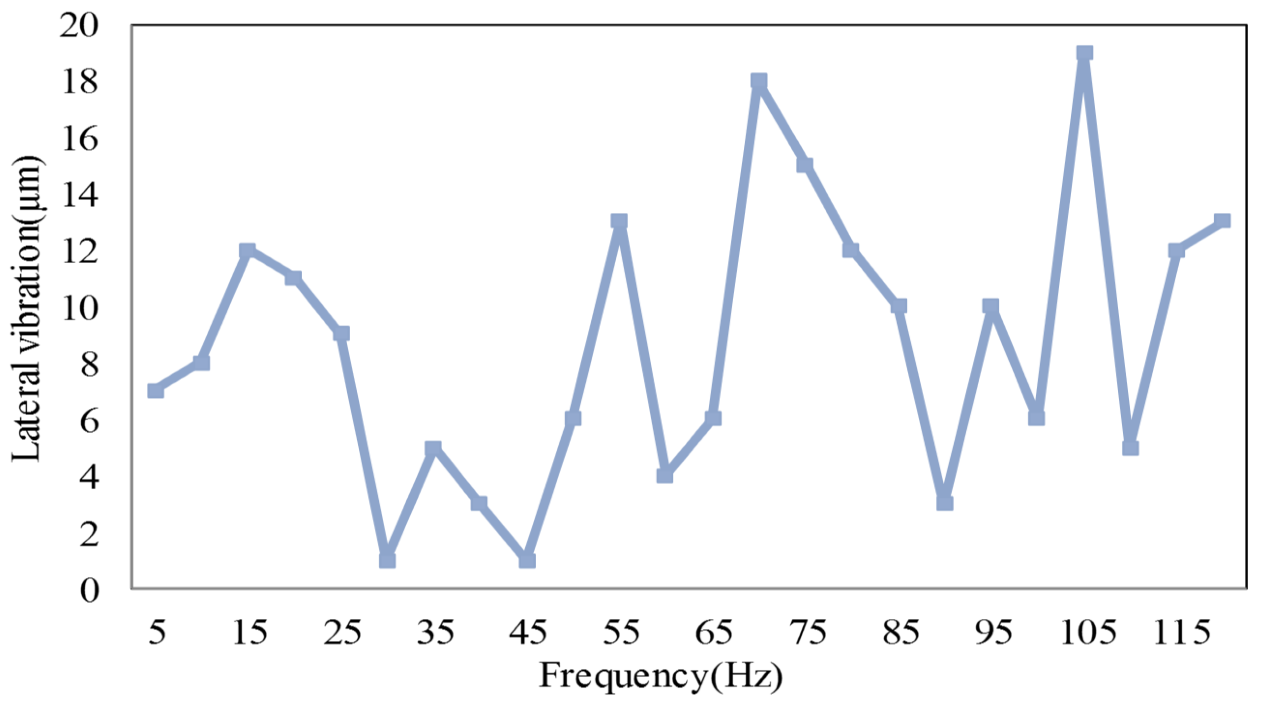
Figure 8.
Comparison between the lateral vibrations of different frequencies of driving signals.

| Replicate | Number of Oocytes Prepared | Number of Oocytes Cleaved | Cleavage (%) |
|---|---|---|---|
| 1 | 13 | 10 | 76.9 |
| 2 | 21 | 17 | 81.0 |
| 3 | 19 | 16 | 84.2 |
| 4 | 25 | 20 | 80.0 |
| 5 | 27 | 22 | 81.5 |
| Total | 105 | 85 | 80.1 |
| Frequency (Hz) | 30 | 45 | ||
|---|---|---|---|---|
| Cleavage (%) | ||||
| Voltage (V) | ||||
| 30 (membrane) | 0 | 90 | ||
| 75 (zona pellucida) | 50 | 100 | ||
| Replicate | Number of Oocytes Prepared | Number of Oocytes Cleaved | Cleavage (%) |
|---|---|---|---|
| 1 | 13 | 12 | 92.3 |
| 2 | 21 | 19 | 90.5 |
| 3 | 19 | 18 | 94.7 |
| 4 | 25 | 22 | 88.0 |
| 5 | 27 | 25 | 92.6 |
| 6 | 12 | 11 | 91.7 |
| Total | 117 | 103 | 91.5 |
© 2016 by the authors; licensee MDPI, Basel, Switzerland. This article is an open access article distributed under the terms and conditions of the Creative Commons Attribution (CC-BY) license (http://creativecommons.org/licenses/by/4.0/).
Share and Cite
MDPI and ACS Style
Ru, C.; Pan, P.; Chen, R. The Development of Piezo-Driven Tools for Cellular Piercing. Appl. Sci. 2016, 6, 314. https://doi.org/10.3390/app6110314
AMA Style
Ru C, Pan P, Chen R. The Development of Piezo-Driven Tools for Cellular Piercing. Applied Sciences. 2016; 6(11):314. https://doi.org/10.3390/app6110314
Chicago/Turabian StyleRu, Changhai, Peng Pan, and Ruihua Chen. 2016. "The Development of Piezo-Driven Tools for Cellular Piercing" Applied Sciences 6, no. 11: 314. https://doi.org/10.3390/app6110314
Note that from the first issue of 2016, this journal uses article numbers instead of page numbers. See further details here.