A Miniature 3D Printed On-Off Linear Pneumatic Actuator and Its Demonstration into a Cartoon Character of a Hopping Lamp


1
Department of Mechanical Engineering, The University of Texas at San Antonio, One UTSA Circle, San Antonio, TX 78249, USA
2
Department of Mechanical and Industrial Engineering, University of Illinois at Chicago, 842 W. Taylor Street, Chicago, IL 60607, USA
*
Author to whom correspondence should be addressed.
Actuators 2019, 8(4), 72; https://doi.org/10.3390/act8040072
Submission received: 23 August 2019
/
Revised: 25 September 2019
/
Accepted: 15 October 2019
/
Published: 17 October 2019
(This article belongs to the Special Issue Pneumatic Actuators for Robotics and Automation)
Abstract
:Although 3D printing has been extensively used to create passive machines and mechanisms, 3D printing of actuators is a relatively new concept. 3D printing of actuators allows greater customization, accelerates the design and development, and consequently saves time and money. We present the design and fabrication of a 3D printed, miniature size, double-acting, On-Off type, linear pneumatic actuator. The actuator has an overall length of 8 cm, a bore size of 1.5 cm, and a stroke length of 2.0 cm. The overall weight is 12 gm and it generates a peak output power of 2 W when operating at an input air pressure of 40 psi ( kPa). This paper demonstrates novel methods to solve the challenges that arise during fabrication that include: (1) chemical post-processing to achieve airtight sealing and a smooth surface finish, (2) strategic placement of a metallic part within 3D printed plastic for higher strength, (3) design of an airtight seal between the cylinder and piston head, (4) chemical bonding of printed parts using adhesive, and (5) use of a lubricant to reduce friction and improve force generation. The power-to-weight ratio of our actuator is comparable to that of high-end commercial actuators of similar size. The utility of the actuator is demonstrated in a series of jumping experiments with the actuator and by incorporating the actuator into a hopping robot inspired by Disney/Pixar Luxo lamp. We conclude that 3D printed pneumatic actuators combine the high power of pneumatics with the low weight of plastics, and structural strength through the selective placement of metal parts, thus offering a promising actuator for robotic applications.
1. Introduction
The traditional use of 3D printing has been to create custom parts with intricate shapes including overhangs, recesses, and interleaved parts. More recently, 3D printing has been used to create kinematic mechanisms with gears, linkages [1,2] and machines that are powered by their natural dynamics and geometry [3]. However, such passive machines and mechanisms have very little utility unless they are endowed with actuators. In this paper, we explore the use of 3D printing to create a pneumatic actuator and its utility on a legged robot.
The most straightforward technique of creating actuated robots is to first 3D print the individual components, assemble them, and then integrate electric motors (e.g., the humanoid poppy [4]). A more subtle approach is to create 3D printed joints that are co-printed within the machine structure and embed actuators by stopping the print process [5]. The benefit of this method is the elimination of the assembly process, thus saving time. However, the approach is more complicated: visual cues need to be set up to stop the printing process to embed actuators and joints need to be designed so that excess material around the joints can be easily removed post-printing. More recently, Maccurdy et al. [6] created a non-assembly hexapod robot that included bellow actuators, gear pumps, and soft grippers, all of which were printed as a single integrated assembly using a multi-material printer. The gear pump forces the fluid through the transmission thus moving the robot legs in a predefined fashion to create forward movement.
There has been considerable research on creating actuators for soft robots. For example, Peele et al. [7] have created a pneumatic bellow type actuator using stereolithography and fabricated an octopus tentacle. Tolley et al. [8,9] created a jumping robot with functionally graded stiffness that is rigid at the core and soft on its exterior. It is powered by an explosive reaction between butane and oxygen that generates a high thrust. Moog Inc. created a compact hydraulic actuator by using a 3D printer that can print metal. They have successfully integrated the hydraulic actuator with a two-stage servo control valve, position and pressure sensors, and onboard electronics [10]. Wei [11] created a pneumatic stepper motor which consists of a central fixed gear and an outer rotary gear. The three air cylinders on the outer side of the rotary gear are able to move the rotary gears either in steps or in a continuous mode. The actuator was used to create a robot that performed a pick and place operation.
Although 3D printing has been used to create soft pneumatic actuators where compressed air moves a springy surface to produce movement, conventional linear pneumatic actuators with sliding joints have not been investigated before and are the main novelty of this work. The fundamental challenges in creating such an actuator are achieving leak-proof, low friction, and a strong actuator that can withstand relatively high air pressure. We address these challenges by using the chemical treatment after 3D printing to achieve a strong and leak-proof cylinder, design of cylinder and the piston head to achieve a tight fit for the O-ring, supplementing plastic with metallic inserts in high-stress areas to improve durability, and the lubrication of surfaces to achieve low friction movement.
The paper is organized as follows. We present the actuator’s design and fabrication in Section 2. Next, in Section 3 we present the actuator’s testing and demonstration as a single leg hopping and jumping robot, and its incorporation into a legged robot inspired by Disney/Pixar Luxo lamp. The discussion is in Section 4 followed by the conclusion in Section 5.
2. Fabrication of the Pneumatic Actuator
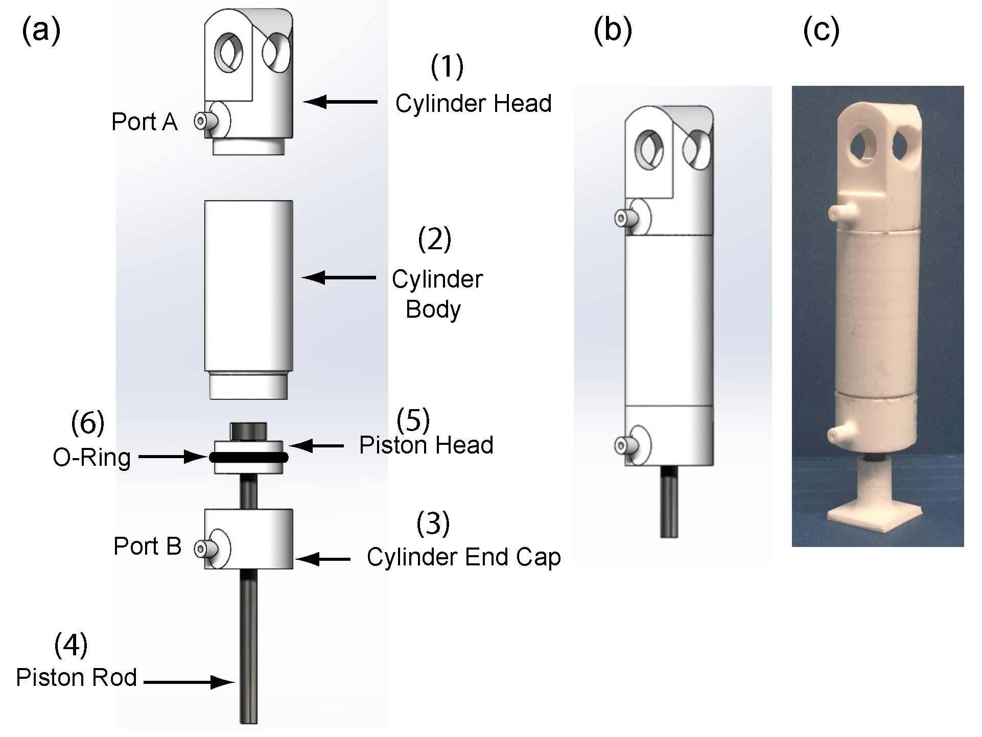
Figure 1a shows an exploded view of the different parts that constitute the actuator. The cylinder head (1), cylinder body (2), cylinder end cap (3), and piston head (5), all of which are 3D printed in the orientation shown in Figure 2a. The piston rod (4), a galvanized steel bolt and the rubber O-ring (5) are off-the-shelf components. The Ultimaker 3 Extended, a hobby-grade Fused Deposition Modeling printer, was used to fabricate the 3D printed components. The print settings were chosen to allow for maximally dense printed components. The critical printer settings included: 100% infill density, extra-fine profile, layer height of mm, and a printing temperature of 225 C. The complete assembly and fabricated actuator are shown in Figure 1b,c respectively.
Our most successful 3D printed actuator had an overall size of cm, bore of cm, stroke of 2 cm, cylinder thickness of cm, mass of 12 gm, and a peak output force and power of 3 N and W, respectively, at an air supply pressure of 40 psi ( kPa).
2.1. Cylinder
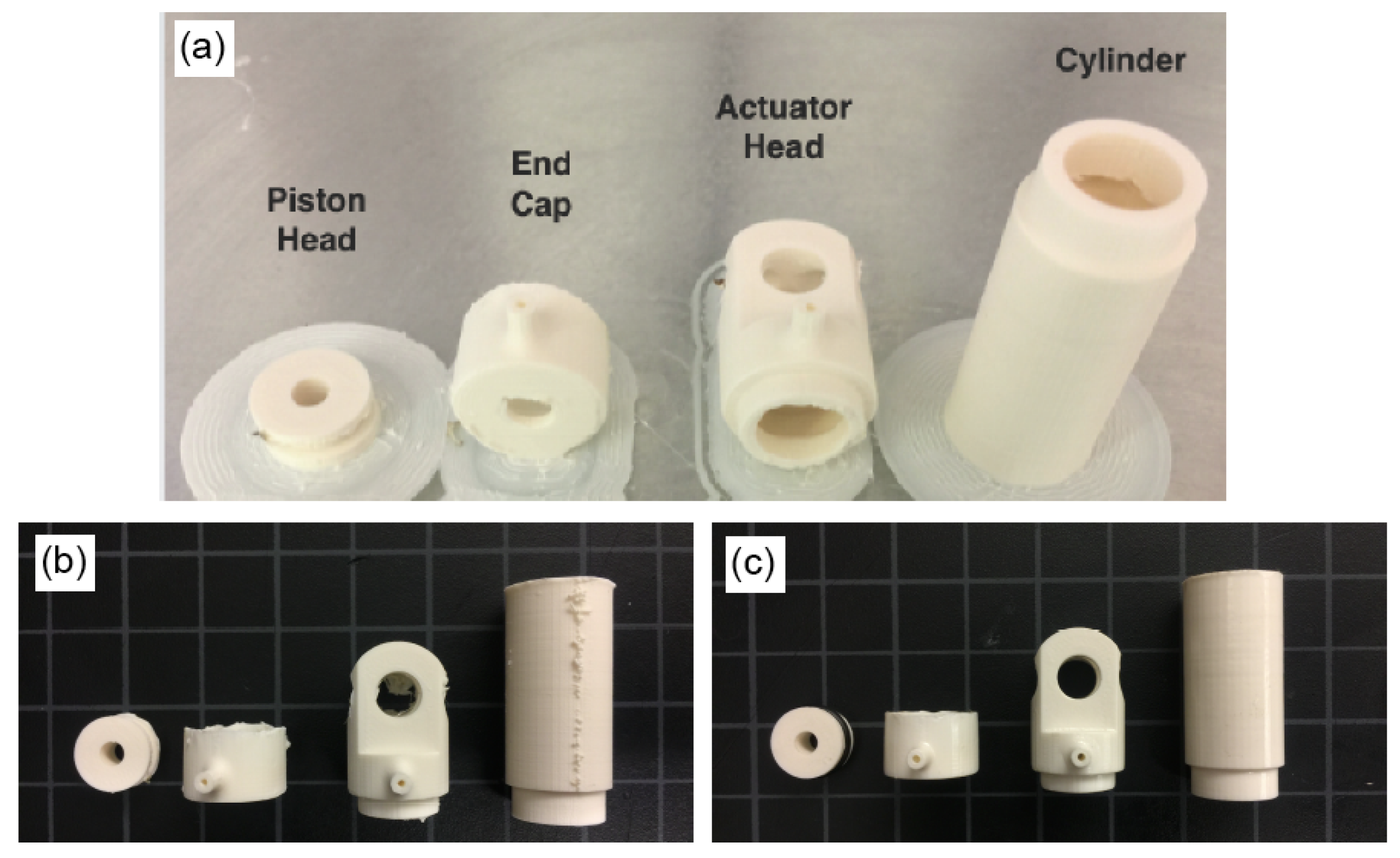
The cylinder body, head, and end cap were 3D printed using ABS (Acrylonitrile Butadiene Styrene) as separate parts. In spite of printing with a fine resolution, the resulting parts have a rough surface finish leading to high friction and a presence of fine pores leading to air leakage. We resolved both of these issues by dipping individual cylinder components in acetone for a short period of time. Acetone is a solvent and has the ability to dissolve the ABS plastic [12]. We have observed that if the ABS part is placed in the acetone for the correct amount of time, it dissolves just enough ABS to provide a smooth surface finish thus sealing the pores. The dipping time is critical as a very short period of time is inadequate while a long period of time would cause a substantial portion of ABS is dissolved, leading to loss of ABS plastic and therefore reducing material strength. More details on determining the optimum dip time is in Section 2.5. Figure 2b,c shows the surface finish of the different components before and after treatment, respectively. Figure 3a,b shows a close of the surface finish before and after acetone treatment The head, body, and end cap were adhered using acrylic-based adhesive (Loctite, Henkel AG and Company, Düsseldorf, Germany).
2.2. Piston Rod
The piston rod is subject to significant compressive stresses during its operation. Our initial attempts at printing the piston rod led to actuator failure due to the breaking of the piston rod. We then used a galvanized steel bolt in place of the 3D printed one and it was found to be very durable.
2.3. Piston Head
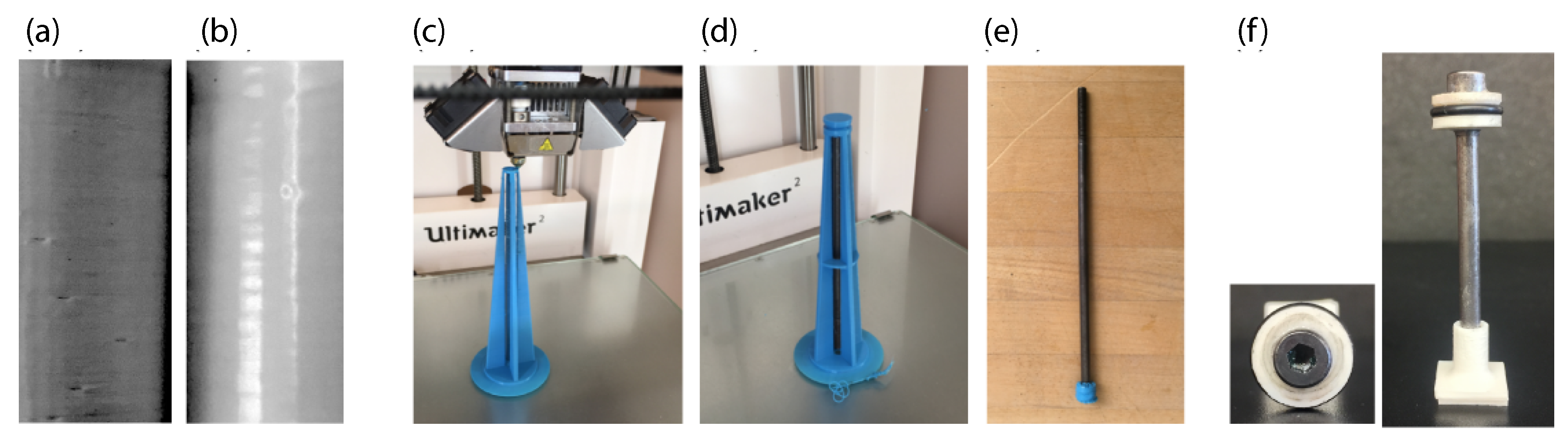
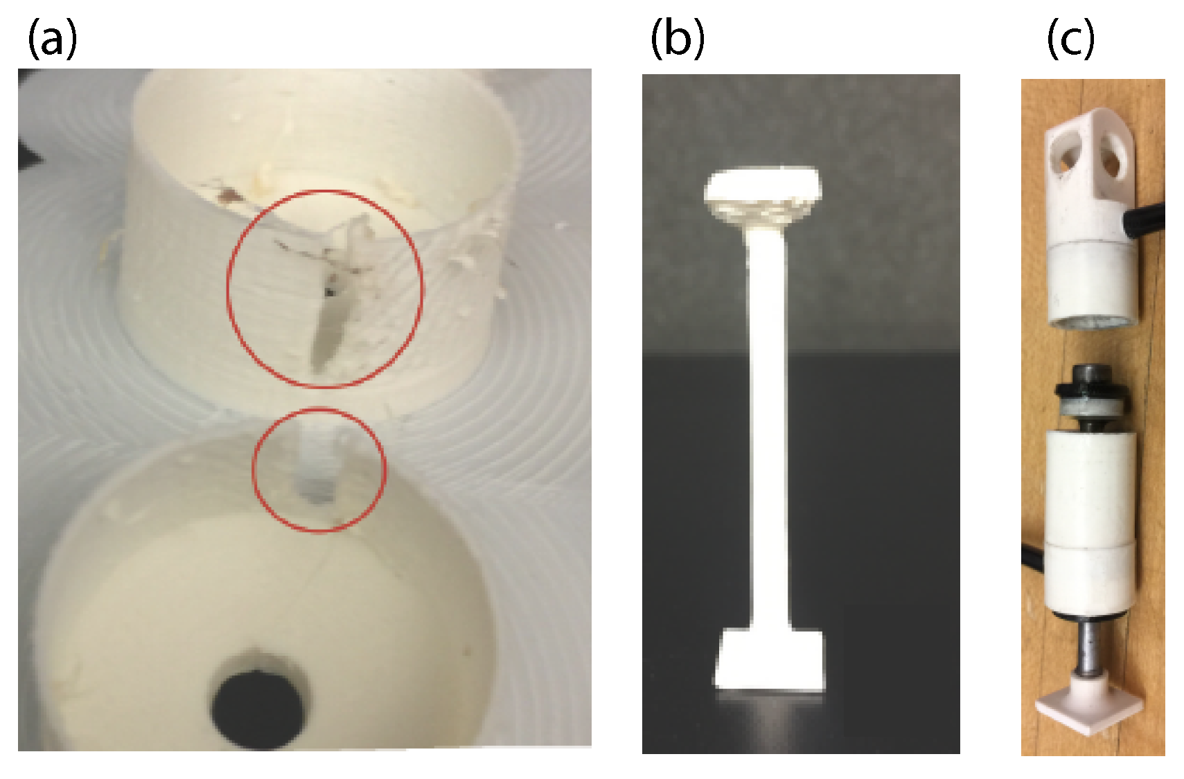
One of the advantages of 3D printing is the ability to embed materials by stopping the print process. We used this feature to 3D print the piston head on the steel bolt as shown in Figure 3b–d. First, we 3D printed a scaffold as shown in Figure 3c. We used visual cues to stop the print process in order to place the steel bolt between the scaffolds. Note that the steel bolt is placed vertically with the bolt head at the top. Then, the piston head is printed on the bolt head using the scaffolds as support material as shown in Figure 3d. Finally, the scaffolds are removed leaving the piston head on top of the steel bolt as shown in Figure 3e. However, the process of embedding takes a long time and results in wastage of significant ABS plastic. We tried an alternate approach of first 3D printing the piston head. Then, we used an acrylic-based adhesive (Loctite, Henkel AG and Company) to attach the piston head to the piston. Loctite has an epoxy resin and a hardener that forms a strong bond between metal and plastic. The primary advantages of using Loctite are providing a bond as well as a seal, there is a marginal increase in the weight, and it provides a means for quick, yet strong assembly. After assembly, we then applied a waterproof grease (Danco, Inc., Irving, TX, USA) on the piston head and the inner surface of the cylinder to provide lubrication between the surfaces (see Figure 3f).
2.4. Assembly between the Piston Head and Cylinder
We used a rubber O-ring (Danco, Inc., Irving, TX, USA) to provide a tight seal between the piston head and the cylinder. We created a groove in the middle of the 3D printed piston head. The diameter of the groove was slightly larger than the inner radius of the O-ring. The diameter of the cylinder was selected to have a compression squeeze of less than 5%, (an empirical choice used in O-ring applications). The compression squeeze is defined as the percentage difference between the original O-ring cross-section before installation and the final cross-section after installation. Our final design had a compression squeeze of %. During O-ring installation design, a stretch greater than 5% is not recommended as it may lead to loss of seal compression. The final piston head and O-ring design are shown in Figure 3f.
2.5. Improving Surface Finish, Reducing Air Leakage Through Acetone Treatment
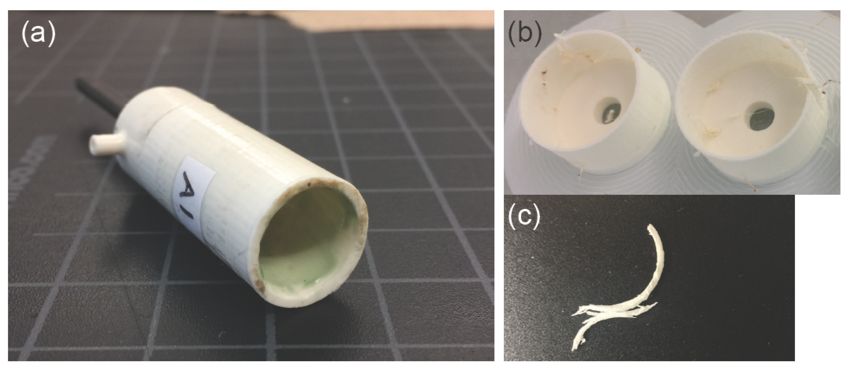
The surface finish of the cylinder is rough because the cylinder is 3D printed in the axial direction along the length as concentric rings stacked on top of each other (see Figure 4a). There is a single ring per layer and the thickness of each ring is equal to the size of the printer nozzle hole. Gravity helps to fuse the concentric layers together. However, occasionally these layers do not fuse properly leading to a defective print as shown in Figure 4b. Furthermore, Figure 4c shows a ring that separated from the cylinder. The lack of a strong contact between adjacent concentric rings is the main reason there is air leakage.
Acetone may be used to improve the surface finish of the rough surface. In addition, acetone should also help to fuse concentric rings more firmly thereby reducing air leakage. Acetone can dissolve ABS plastic and by controlling the dip time it is possible to ensure that the right amount of ABS is dissolved to provide a smooth surface without affecting structural integrity [13]. Thus, it is critical to determine the correct dip time.
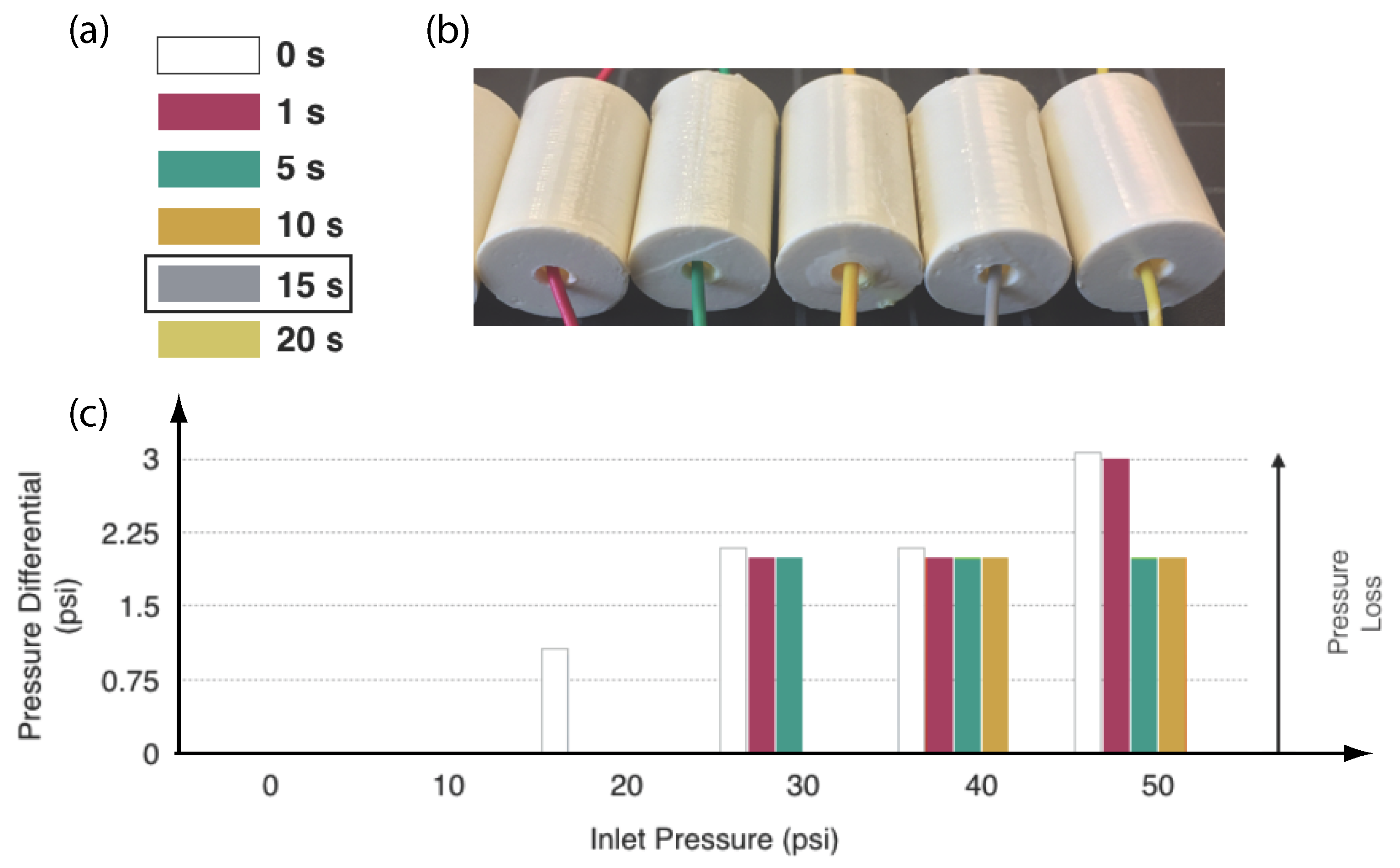
To determine the optimum dip time we prepared 7 identical cylinders. Each of these cylinders were dipped in acetone for different times, 0 s corresponding to no dipping in acetone, 1, 5, 10, 15, and 20 s as shown in Figure 5a,b. One end of each cylinder was attached with tubing to a constant inlet pressure of compressed air ranging from 10 to 50 psi ( kPa to kPa). At each interval of increasing the pressure by 10 psi ( kPa), the value of the pressure gauge also connected via tubing to the opposite end of the cylinder was recorded. The recorded values for the pressure differentials of the various combinations of treated specimens and inlet pressures are shown in Figure 5c. It may be seen that as the inlet pressure is increased, the pressure loss increased. Also, as the treatment time increased, the pressure loss time decreased. At 15 and 20 s, there was no pressure loss. Based on this experiment, we chose the optimum dip time as 15 s as we noticed no pressure loss. The pressure loss may be attributed to the pores in the cylinder surface due to a lack of sufficiently dense filling with our hobby-grade printer.
3. Experimental Methods, Results, and Demonstrations
We present the results of testing the actuator in a series of experiments. First, we constrained the actuator to a sliding rail to measure the force and power generation capabilities. Next, we demonstrate unconstrained hopping and jumping motion by adding supports. Next, the actuator was incorporated on a Disney/Pixar inspired robot, Luxo Junior. A video illustrating the actuator’s performance is in reference [14]. Finally, we end up enumerating various actuator failures during manufacture and testing.
3.1. Experimental Set-Up for the Pneumatic Actuator Testing and Results
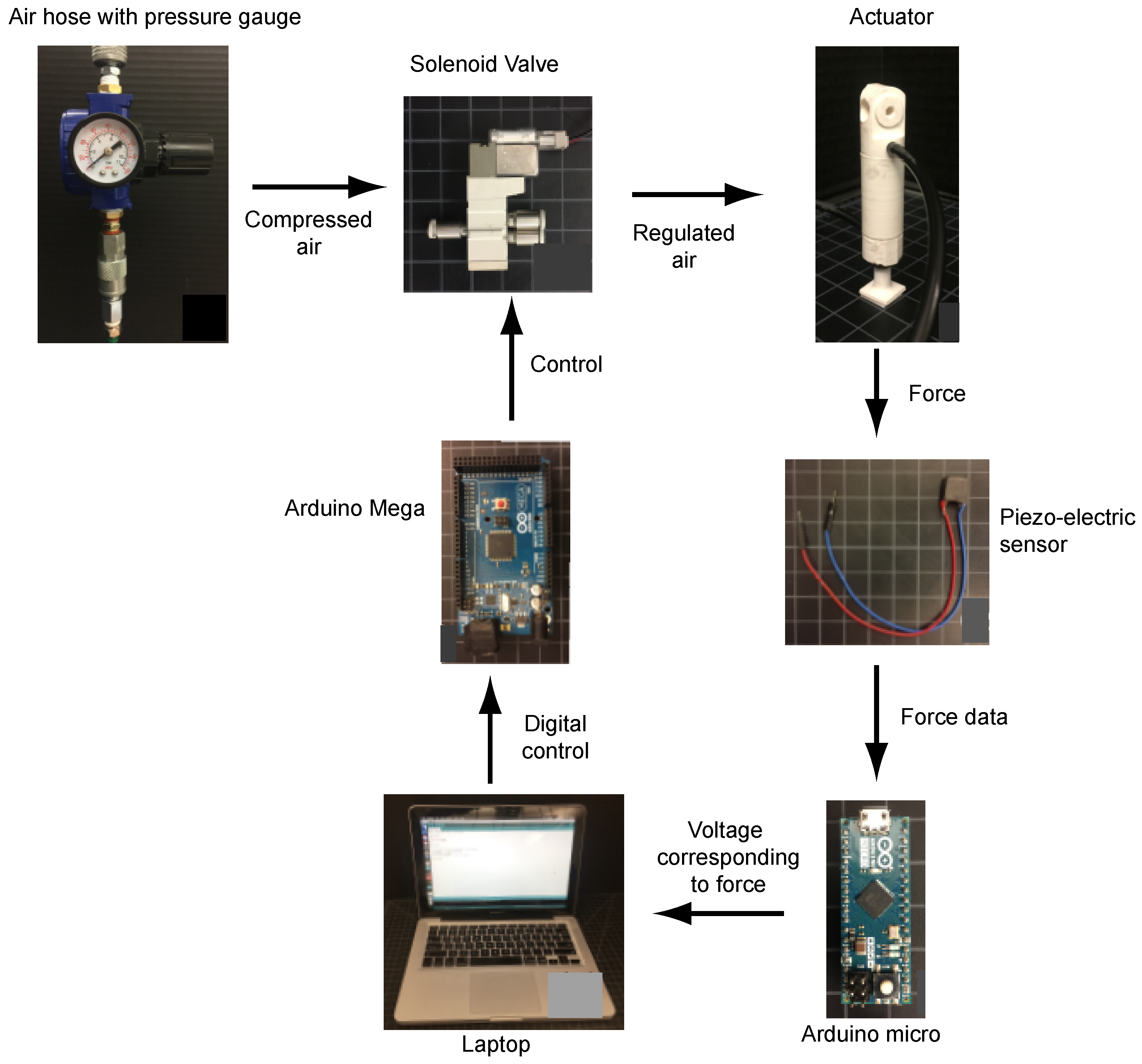
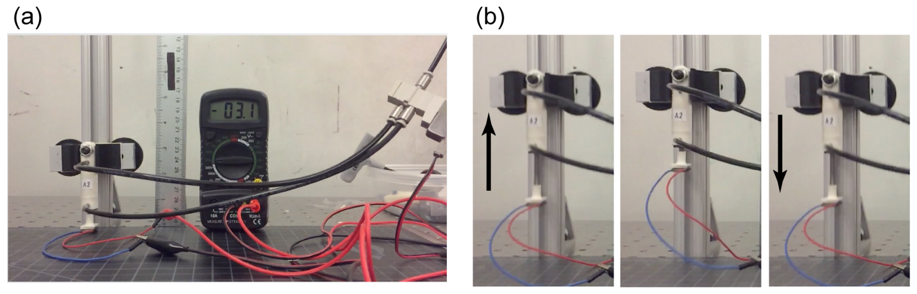
Figure 6 shows the experimental setup to control and measure data from the pneumatic actuator and Figure 7a shows the experimental setup for the pneumatic actuator to constrain motion in a vertical direction to enable easy measurement of the output force and power. A compressed air hose equipped with a pressure gauge was connected to the inlet port of a double-acting solenoid valve (Vex Robotics Inc., Greenville, TX USA) through a 4 mm outer diameter rubber tubing. The two output ports of the double-acting solenoid were connected to ports, A and B, of the 3D printed actuator. The double-acting solenoid valve is controlled by an Arduino Micro that allowed the pressurized air to flow between port A and B, extending and retracting the piston rod. A 3D printed flat square end cap was fixed to the free end of the piston rod to provide ample cross-sectional area for stable actuator-ground interaction. We fabricated a piezoelectric sensor (not 3D printed) and adhered it to the base of the square plate to measure the force produced by the actuator. The piezoelectric sensor consists of Lead Zirconate Titanate as the piezoelectric sensor (a footprint of 1 cm × 1 cm and 0.2 cm thickness) that is sandwiched between two copper electrodes. The calibration equation for a piezo sensor is
where F is the force, C is the capacitance, V is the measured voltage, d is the piezoelectric constant. The capacitance was measured using a multimeter and was found to be nF and the piezoelectric coefficient was measured with a piezometer and was pc/N. In experiments, the voltage V was measured using an Arduino Micro and saved to the computer. The voltage was then post-processed using the above equation to find the peak actuator force . A 240 frame rate camera was used to record the motion of the actuator. From the video, we computed the average speed of the piston rod. The peak output power was computed as, .
The Arduino Micro was controlled to turn the actuator in an open-loop fashion. The only two parameters are the ON and OFF times for the double-acting solenoid valve and were tuned iteratively by trial and error. The successful time delay for the actuator was determined by the ability to achieve a full in-stroke before making ground contact and full out-stroke while being in contact with the ground in order to generate a maximum thrust. Figure 7b shows a successfully tuned actuator moving on the rail.
The peak output power is 2 W at a supply pressure of 40 psi ( kPa), maximum jump height is cm, which is approximately 2 times the stroke length.
3.2. Two Demonstrations of the Actuator: Jumping Robot and Cartoon Character of a Hopping Robot
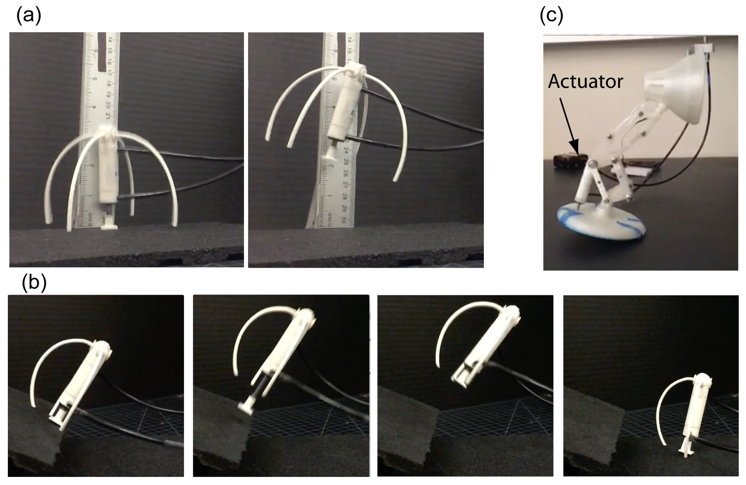
The actuator can be used as a standalone robot by providing external supporting legs. Figure 8a,b show unsupported hops of the actuator with four and three supports, respectively. In Figure 8a, the actuator performs repeated vertical jumps from a horizontal plane. The average jump height is about cm which is about times the stroke length. The maximum jump recorded was cm and is about 4 times the stroke length. These jumps are higher than those achieved using a support rail in part due to the overall lower weight and the elastic energy stored in the supporting legs. In Figure 8b, the actuator takes off from an inclined plane and successfully lands on the ground.
We also created a hopping lamp based on Disney/Pixar Luxo character. Past work has considered actuating the lamp using electric motors [15]. The actuator was connected between the base plate and the vertical post of the lamp at a slight incline to the vertical. The actuator out-stroke timing was adjusted to provide sufficient thrust to the lamp. The thrust provided by the actuator powers the lamp forward by tipping and sliding motion. There was no flight phase, unlike the Pixar animation of the lamp. The speed of the lamp was cm/s.
3.3. Actuator Failures
We list various instances of actuator failure pre- or post-printing and during testing. Figure 9a shows a cracked cylinder. Although the thickness was large enough to be printed properly, it cracked when subject during acetone treatment. Figure 9b shows an attempt to 3D print the piston. After acetone treatment, the piston rubberized and deemed unfit for assembly. This was due to a poor choice of dipping time. In Section 2.5 we indicated an experimental procedure to determine the optimum dip time. Although all tests were done up to 50 psi ( kPa), we wanted to check the limits of our actuator. The actuator was able to bear a static pressure of 100 psi ( kPa), however, when subject to a pressure of 75 psi ( kPa) under relatively low cycling, the cylinder ruptured in the transverse direction as shown in Figure 9c.
4. Discussion
We have successfully demonstrated the development of miniature size, 3D printed linear pneumatic actuator, using a fused deposition modeling printer. We demonstrated both supported and unsupported vertical jumping of the actuator. Due to lightweight and high power capacity, the actuator achieved an average jump height of 2 stroke lengths and maximum jump height of 4 stroke lengths. Furthermore, we incorporated the actuator into a Disney/Pixar Luxo inspired lamp to demonstrate the actuator’s utility in legged robotic applications.
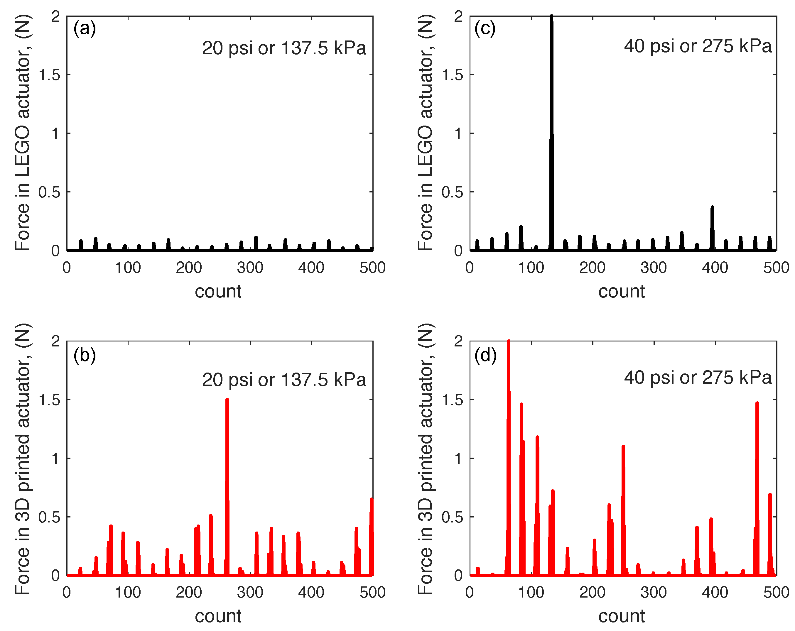
We compared our actuator with a hobby-grade pneumatic actuator by LEGO and an industrial-grade electric actuator by Faulhaber [16]. We repeated the constrained rail test for the LEGO actuator. Figure 10 compares the forces developed in the LEGO actuator and our 3D printed actuator for 2 different input air pressures of 20 psi ( kPa) and 40 psi (275 kPa). It is clear that our 3D printed actuator produces high output pressure than the LEGO actuator. Note that the forces shown are not repeatable due to two factors: (1) the lack of repeatable analog input to the valves by the Arduino due to its limited bandwidth, and (2) the bouncing off of the actuator after landing. We used values reported in the Faulhaber motor specification sheet for our comparison. The results are tabulated in Table 1. The LEGO actuator and our actuator are comparable in both mass and size. However, our actuator produced times the peak force, was about 2 times faster, and consequently had power of times that of the LEGO actuator. The larger power in our actuator compared to the LEGO actuator may be attributed to the low sliding friction in our linear actuator. We achieved a smooth surface by acetone treatment followed by the application of lubricant on the inner surface as well as the piston head. In fact, when we tried to manually move the piston by hand, we found that the LEGO actuator needed substantially large force compared to our actuator, which is probably due to lack of enough lubrication at the piston-cylinder assembly. We believe that the LEGO actuator is produced from injection molding while our actuator is 3D printed. The LEGO actuator costs approximately USD (market price) that includes the cost of materials, labor, and overhead. On the other hand, our 3D printed actuator requires material worth USD (USD for the steel bolt, for 50 gm ABS, and for the O-ring). Since our 3D printed actuator was hand-made versus the LEGO actuator which is mass-produced using injection molding, it is difficult to compare the two based on pricing. Our actuator was comparable in size to the Faulhaber electric motor. The peak power of our actuator was in the range of the continuous power output of the Faulhaber motor.
The surface treatment of ABS plastic performs three important functions. First, it seals the pores of the 3D printed actuator, thus preventing air leakage through the cylinder’s surface. Secondly, it produces a reduced friction surface, allowing for relatively smooth interface motion between the O-ring and the inner surface of the cylinder. Third, the cylinder surface is strengthened due to the acetone treatment. For example, the untreated actuator cylinder failed in the transverse direction when subjected to 70 psi ( kPa) pressure and a relatively low cycle rate. However, the cylinder that was acetone treated did not show any signs of failure at equivalent pressures. For our earlier prototypes, we used Polylactic Acid (PLA), which is the other dominant Fused Deposition Modeling (FDM) filament. Due to printer limitations, PLA, like ABS, produces parts with pores. Since acetone does not dissolve PLA, we were unable to seal the pores and thus unable to create a PLA-based 3D printed actuator.
An outstanding challenge in actuator design is to create a high power-to-weight actuator. The use of plastic material as the main fabrication material allows us to keep the design lightweight while capitalizing on the high force generation capability of compressed air. Furthermore, the use of acetone to smooth the surfaces and the use of waterproof grease on the inner surface of the cylinder provides a low friction surface. This reduces unnecessary losses and allows for high force and power generation. Although the strength of plastic can be an issue, we found that if the actuator is designed properly (i.e., sufficiently thick wall, avoiding kinks or corners to prevent stress concentration corners) and printed in the correct orientation, the actuator can be of sufficient strength. Another less exploited feature is the ability to stop the print process to embed sensors, motors, structural components, and fixtures that can provide additional functionality [5]. We have exploited this feature by using a metallic piston rod, high stress-bearing part, in a fluidic actuator.
There is an increased drive towards creating designs that are 3D printed in a single pass without assembly. Our actuator does not fit this bill and requires substantial post-processing and manual assembly. In addition, the actuator also needed metal inserts (i.e., the piston) to be able to bear the high compressive forces experienced during its operation. However, our actuator is tiny and has the potential for the nontrivial addition of added sensors (e.g., position sensors). It is currently limited to simple On-Off type applications. Ultimately, adding high bandwidth position and force control will expand the utility of such an actuator (e.g., [17]). In our experience, limitations of FDM based 3D printers such as low printer resolution, lack of isotropy of the finished parts, and poor quality control prevent the rapid prototyping of machines and mechanisms where high strength is desired.
5. Conclusions
We conclude that by using judicious design choices, it is possible to 3D print pneumatic actuators that have performance comparable to high-end commercial actuators in terms of power-to-weight ratio. A major benefit of 3D printed pneumatic actuators is that they combine the high power of pneumatics with the low weight of plastics. Furthermore, one may capitalize on the use of chemical treatment post-printing and waterproof grease to reduce friction that can improve force generation, and the ability to selectively place metallic parts to improve strength. With the advent of cheaper and more capable 3D printers, we expect to see the steady rise of high power-to-weight ratio 3D printed actuators, leading to further improvements in robot design and control.
Supplementary Materials
Supplementary File 1Author Contributions
C.L.N. designed the hardware and did all the experiments. C.L.N. and P.A.B. wrote the paper together.
Acknowledgments
This work was funded by the University of Texas at San Antonio, Office of the Vice President for Research.
Conflicts of Interest
The authors declare no conflict of interest.
References
- Thomaszewski, B.; Coros, S.; Gauge, D.; Megaro, V.; Grinspun, E.; Gross, M. Computational design of linkage-based characters. ACM Trans. Graph. (TOG) 2014, 33, 64. [Google Scholar] [CrossRef]
- Coros, S.; Thomaszewski, B.; Noris, G.; Sueda, S.; Forberg, M.; Sumner, R.W.; Matusik, W.; Bickel, B. Computational design of mechanical characters. ACM Trans. Graph. (TOG) 2013, 32, 83. [Google Scholar] [CrossRef]
- Treviño, C.L.; Galloway, J.D., II; Bhounsule, P.A. A Three-Dimensional Printed, Nonassembly, Passive Dynamic Walking Toy: Design and Analysis. J. Mech. Robot. 2018, 10, 061009. [Google Scholar] [CrossRef]
- Lapeyre, M.; Rouanet, P.; Grizou, J.; N’Guyen, S.; Le Falher, A.; Depraetre, F.; Oudeyer, P.Y. Poppy: Open source 3d printed robot for experiments in developmental robotics. In Proceedings of the 2014 Joint IEEE International Conferences on Development and Learning and Epigenetic Robotics (ICDL-Epirob), Genoa, Italy, 13–16 October 2014; IEEE: Piscataway, NJ, USA, 2014; pp. 173–174. [Google Scholar]
- De Laurentis, K.J.; Mavroidis, C.; Kong, F.F. Rapid robot reproduction. IEEE Robot. Autom. Mag. 2004, 11, 86–92. [Google Scholar] [CrossRef]
- MacCurdy, R.; Katzschmann, R.; Kim, Y.; Rus, D. Printable hydraulics: A method for fabricating robots by 3D co-printing solids and liquids. In Proceedings of the 2016 IEEE International Conference on Robotics and Automation (ICRA), Stockholm, Sweden, 16–21 May 2016; IEEE: Piscataway, NJ, USA, 2016; pp. 3878–3885. [Google Scholar]
- Peele, B.N.; Wallin, T.J.; Zhao, H.; Shepherd, R.F. 3D printing antagonistic systems of artificial muscle using projection stereolithography. Bioinspiration Biomim. 2015, 10, 055003. [Google Scholar] [CrossRef] [PubMed]
- Tolley, M.T.; Shepherd, R.F.; Karpelson, M.; Bartlett, N.W.; Galloway, K.C.; Wehner, M.; Nunes, R.; Whitesides, G.M.; Wood, R.J. An untethered jumping soft robot. In Proceedings of the 2014 IEEE/RSJ International Conference on Intelligent Robots and Systems (IROS 2014), Chicago, IL, USA, 14–18 September 2014; IEEE: Piscataway, NJ, USA, 2014; pp. 561–566. [Google Scholar]
- Bartlett, N.W.; Tolley, M.T.; Overvelde, J.T.; Weaver, J.C.; Mosadegh, B.; Bertoldi, K.; Whitesides, G.M.; Wood, R.J. A 3D-printed, functionally graded soft robot powered by combustion. Science 2015, 349, 161–165. [Google Scholar] [CrossRef] [PubMed] [Green Version]
- Murray, C. Smart Actuator Propels Hydraulic Beast of Burden. 2017. Available online: https://www.designnews.com/content/smart-actuator-propels-hydraulic-beast-burden/94019613839303 (accessed on 23 August 2019).
- Wei, Y.; Chen, Y.; Yang, Y.; Li, Y. Novel design and 3-D printing of nonassembly controllable pneumatic robots. IEEE/ASME Trans. Mechatron. 2016, 21, 649–659. [Google Scholar] [CrossRef]
- Garg, A.; Bhattacharya, A.; Batish, A. On surface finish and dimensional accuracy of FDM parts after cold vapor treatment. Mater. Manuf. Process. 2016, 31, 522–529. [Google Scholar] [CrossRef]
- Takagishi, K.; Umezu, S. Development of the improving process for the 3D printed structure. Sci. Rep. 2017, 7, 39852. [Google Scholar] [CrossRef] [PubMed]
- Bhounsule, P.A. A Miniature 3D Printed On-Off Linear Pneumatic Actuator with Application to Legged Robots. 2018. Available online: https://youtu.be/DPUNslHj5VE (accessed on 23 August 2019).
- Paluska, D.J. Let There Be Luxo: A Jumping Lamp Sheds Light on Heavy Legged Locomotion. Master’s Thesis, Massachusetts Institute of Technology, Cambridge, MA, USA, 1997. [Google Scholar]
- Faulhaber. DC-Micromotors Series 1219...G. 2017. Available online: https://www.faulhaber.com/en/products/series/1219g (accessed on 23 August 2019).
- Krause, J.; Bhounsule, P. A 3D Printed Linear Pneumatic Actuator for Position, Force and Impedance Control. Actuators 2018, 7, 24. [Google Scholar] [CrossRef]
Figure 1.
An Overview of the 3D printed actuator: (a) an exploded view, (b) assembled view, and (c) 3d printed and assembled.
Figure 1.
An Overview of the 3D printed actuator: (a) an exploded view, (b) assembled view, and (c) 3d printed and assembled.

Figure 2.
(a) The orientation of the different sub-systems of the actuator during 3D printing, (b) parts before surface finishing, and (c) after surface finishing with acetone.
Figure 2.
(a) The orientation of the different sub-systems of the actuator during 3D printing, (b) parts before surface finishing, and (c) after surface finishing with acetone.

Figure 3.
(a) Surface finish before and after (b) acetone treatment. (c) 3D printed scaffold followed by (d) bolt placement and printing the head and (e) bolt with piston head after removing the scaffold. (f) The 3D printed piston head is bonded to piston rod by an adhesive. The O-ring is manually placed in the groove on the piston head.

Figure 4.
(a) A cross-section view of the the actuator cylinder post acetone treatment, (b) a failed print of the cylinder, (c) a ring from the cross-section from a failed print of a cylinder.
Figure 4.
(a) A cross-section view of the the actuator cylinder post acetone treatment, (b) a failed print of the cylinder, (c) a ring from the cross-section from a failed print of a cylinder.

Figure 5.
(a) Experimental times chosen to determine optimum acetone dip time, (b) cylinders (color coded) after acetone treatment, and (c) pressure loss for different inlet pressure for each of the cylinders.
Figure 5.
(a) Experimental times chosen to determine optimum acetone dip time, (b) cylinders (color coded) after acetone treatment, and (c) pressure loss for different inlet pressure for each of the cylinders.

Figure 6.
Experimental setup for testing the pneumatic actuator.

Figure 7.
(a) Experimental setup to measure peak output force and peak output power for the actuator. (b) Actuator performing a successful jump.
Figure 7.
(a) Experimental setup to measure peak output force and peak output power for the actuator. (b) Actuator performing a successful jump.

Figure 8.
(a) Actuator with supports demonstrating unconstrained hopping. (b) Actuator with supports for jumping from an inclined surface to the ground. (c) Actuator incorporated into legged robot based on Disney/Pixar Luxo lamp character.
Figure 8.
(a) Actuator with supports demonstrating unconstrained hopping. (b) Actuator with supports for jumping from an inclined surface to the ground. (c) Actuator incorporated into legged robot based on Disney/Pixar Luxo lamp character.

Figure 9.
A few failed actuator scenarios: (a) Actuator cylinder cracked after acetone treatment due to too thin wall (b) A 3D printed actuator piston after acetone treatment became rubberized and relatively week after an incorrect dip time, and (c) Actuator cracked in the transverse direction after high pressure but low cycling loading.

Figure 10.
Force generated by the actuator on the constrained rail experiment: (a,c) results for LEGO actuator and (b,d) results for 3D printed actuator. Also, (a,b) are for the same input pressure of 20 psi or kPa and (c,d) are for the same input pressure of 40 psi or 275 kPa.
Figure 10.
Force generated by the actuator on the constrained rail experiment: (a,c) results for LEGO actuator and (b,d) results for 3D printed actuator. Also, (a,b) are for the same input pressure of 20 psi or kPa and (c,d) are for the same input pressure of 40 psi or 275 kPa.


Table 1.
Comparing three actuators: 3D printed pneumatic actuator, LEGO pneumatic actuator, and Faulhaber DC motor.
Table 1.
Comparing three actuators: 3D printed pneumatic actuator, LEGO pneumatic actuator, and Faulhaber DC motor.
| Actuator | 3D Printed | LEGO | Faulhaber |
|---|---|---|---|
| Type | Pneumatic Linear | Pneumatic, Linear Linear | Magnetic Rotary |
| Overall length (cm) | |||
| Stroke length (cm) | − | ||
| Outer dia. (cm) | − | ||
| Bore (cm) | |||
| Wall Thickness (cm) | − | ||
| Mass (gm) | 12 | 10 | 11 |
| Max. Force (N) | 3 | − | |
| Max. Speed (m/s) | − | ||
| Power (W) |
Peak power, Continuous Power.
© 2019 by the authors. Licensee MDPI, Basel, Switzerland. This article is an open access article distributed under the terms and conditions of the Creative Commons Attribution (CC BY) license (http://creativecommons.org/licenses/by/4.0/).
Share and Cite
MDPI and ACS Style
Nall, C.L.; Bhounsule, P.A. A Miniature 3D Printed On-Off Linear Pneumatic Actuator and Its Demonstration into a Cartoon Character of a Hopping Lamp. Actuators 2019, 8, 72. https://doi.org/10.3390/act8040072
AMA Style
Nall CL, Bhounsule PA. A Miniature 3D Printed On-Off Linear Pneumatic Actuator and Its Demonstration into a Cartoon Character of a Hopping Lamp. Actuators. 2019; 8(4):72. https://doi.org/10.3390/act8040072
Chicago/Turabian StyleNall, Christian L., and Pranav A. Bhounsule. 2019. "A Miniature 3D Printed On-Off Linear Pneumatic Actuator and Its Demonstration into a Cartoon Character of a Hopping Lamp" Actuators 8, no. 4: 72. https://doi.org/10.3390/act8040072
Note that from the first issue of 2016, this journal uses article numbers instead of page numbers. See further details here.