1. Introduction
The U-shaped actuator is a typical microelectromechanical (MEM) device, which has been used to design and construct several microgrippers reported in the literature. This basically consists of two joined line-shaped beams, where one of them is thin (hot arm), and the other one is wide (cold arm). They are restricted by two anchors [
1]. A smaller beam, called flexure, is found between the wide beam and its corresponding anchor. The U-shaped actuator operation is based on the differential thermal expansion between a pair of arms of different widths [
2]. When the electrical current flows, the higher electrical current density due to the reduced dimensions of the actuator, causes a dissipation of heat, and the thermal expansion of the hot arm reduces the gap between both arms, through the transverse movement that is produced by a mechanical arching action of the hot arm towards the cold arm.
A microgripper can be defined as a microscopic device used to manipulate microscale objects safely [
1]. The microgrippers or micro-tweezers have opened the opportunity to develop manipulation and transport of micro-objects with high precision and reliability in applications such as micro-assembly, micro-robotics, biology, medicine and micro-optics [
3,
4,
5,
6]. According to their working principle, the actuators for MEM microgrippers can be classified into [
1]: electrostatic [
7], electromagnetic [
8,
9], electrothermal [
10], electrochemical [
11] and piezoelectric [
12], and operated using a shape memory alloy [
13]. A review of the state of the art of microgrippers based on microelectromechanical systems (MEMS) is found in [
13]. According to the principle of the microgripper, a wide variety of materials has been used for its manufacture. For example, the processing SOI wafers, shown in [
14], allows selected features of a microdevice to be constructed using the thin buried oxide layer, while using the bulk of the silicon wafer creates devices with high-aspect-ratio for sensing and actuation applications. A summary of the state-of-the-art of the advance that has been obtained in the development of microgrippers is given in
Table 1.
In addition, a survey of microgrippers design can be found in [
29], where distinction between lumped and distributed compliance is used in the Atlas preparation.
On the other hand, a compliant mechanism can be defined as a flexible device that transforms the forces or movements of entrance towards another port in a set of forces or movements of exit through the elastic deformation of the body [
30]. They can be classified as monolithic (when they are made from a single piece) or jointless structures. Microgrippers are manufactured regularly using compliant mechanisms based on electric actuators.
The modeling of each new device is a necessary task to determine its behavior, before manufacturing it, to achieve an efficient use of it and to know in advance its possible applications. ANSYS is a software used to simulate engineering problems using finite element analysis (FEM). This allows to simulate structures or components of machines to determine mechanical and electrical properties, using the three-dimensional model of the object and the physical properties of the material [
31].
This article is focused on a modified U-shaped actuator, which was designed using as reference the one shown in [
2]. This micro-actuator is implemented in the initial microgripper given in [
2]. Electrothermal actuation is considered in both devices. From initial U-shaped actuator design, thin arm and flexure were modified, considering no uniformly distributed mass. The purpose of this work is to observe the improvement in the U-shaped actuator´s performance when these modifications are implemented.
The performance study was done theoretically using a resistive electrical model, and computationally using ANSYS, with Polysilicon as structural material. The main advantage of the modified microgripper, with non-uniform mass distribution, lies in the increment of displacement value (22.33%), but the considerable decrement in force reduces its range of applications to cases when this characteristic would be useful.
The content of this work is organized as follows. Materials and methods are presented in
Section 2, where the U-shaped actuators and microgripper designs are provided as well as the theoretical bases for the calculation of some parameters of the microgripper. Analytical calculations and results obtained from simulation for all structures under analysis are given in
Section 3.
Section 4 discusses the results shown in
Section 3. Finally,
Section 5 summarizes the findings and provides some concluding remarks.
2. Materials and Methods
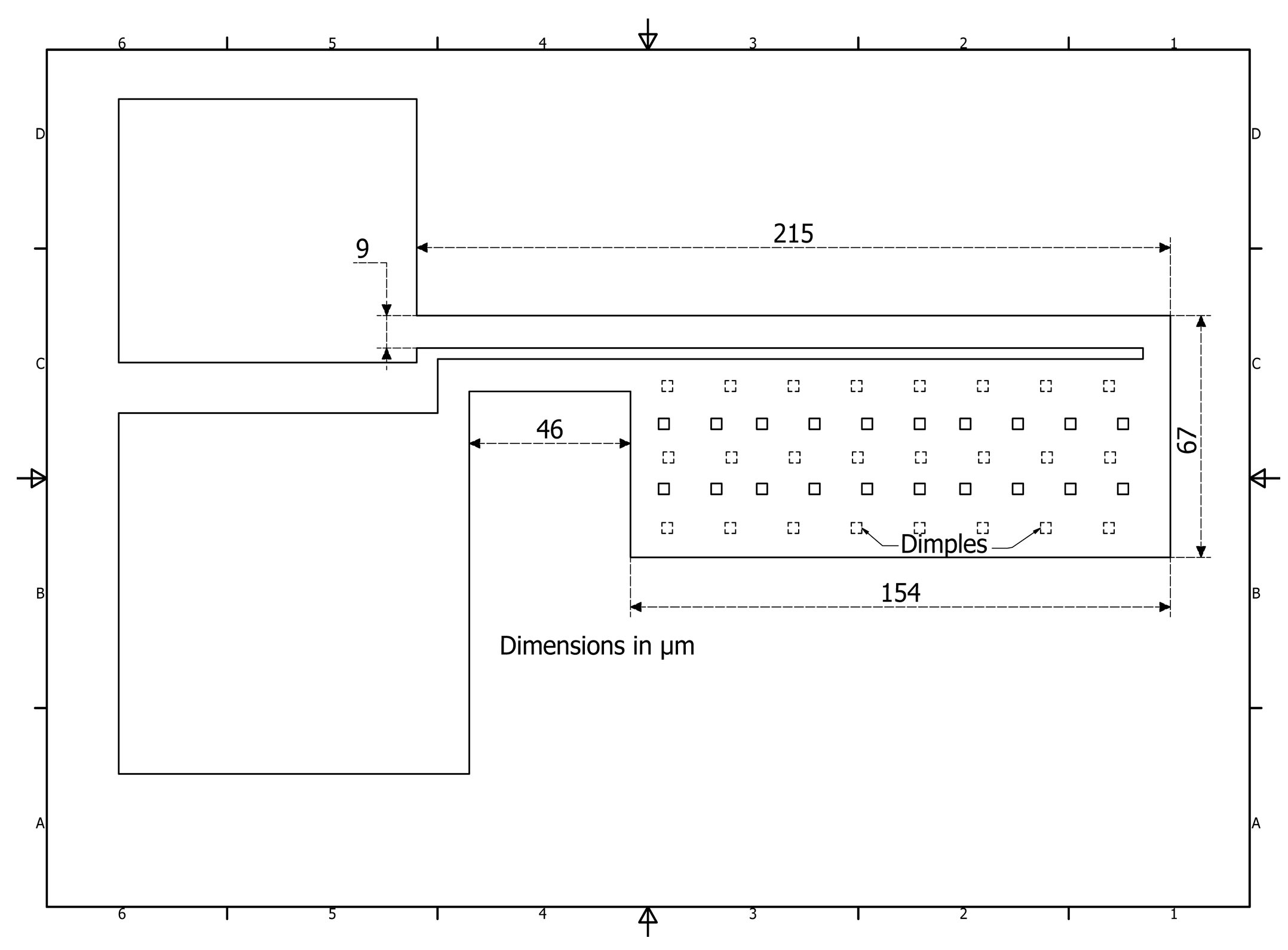
The initial model is the U-shaped actuator given in [
2], (see
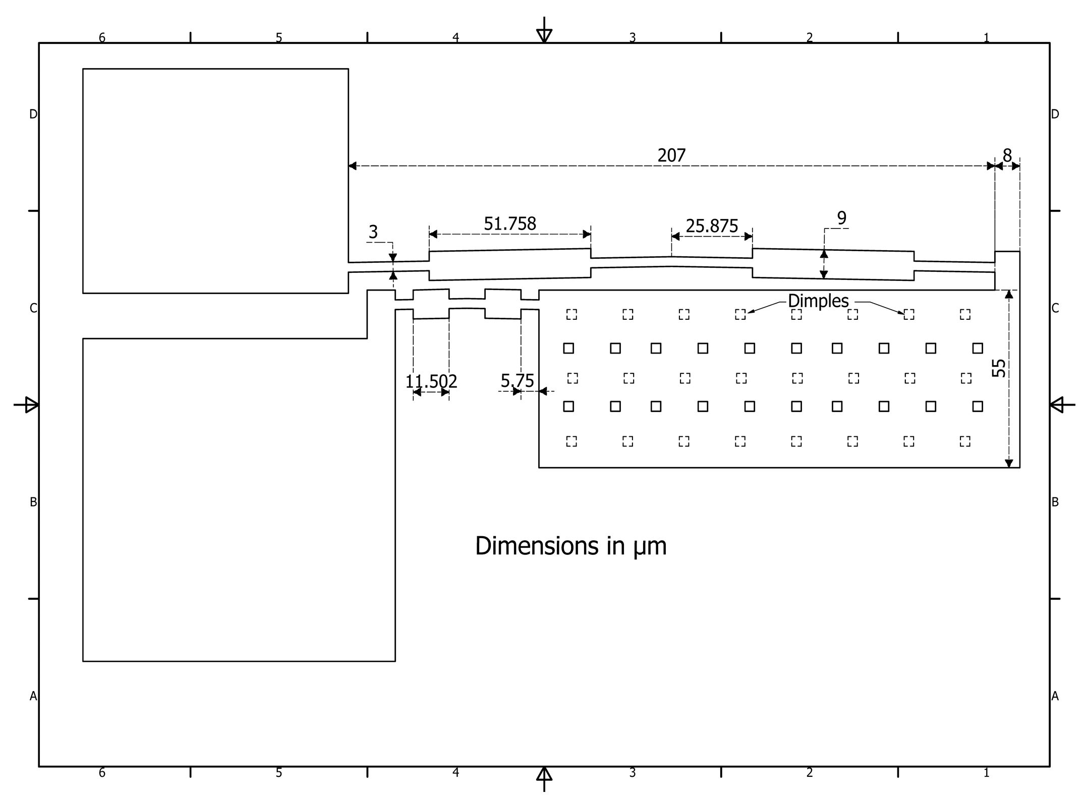
Figure 1). On the base of it, a modified U-shaped actuator (
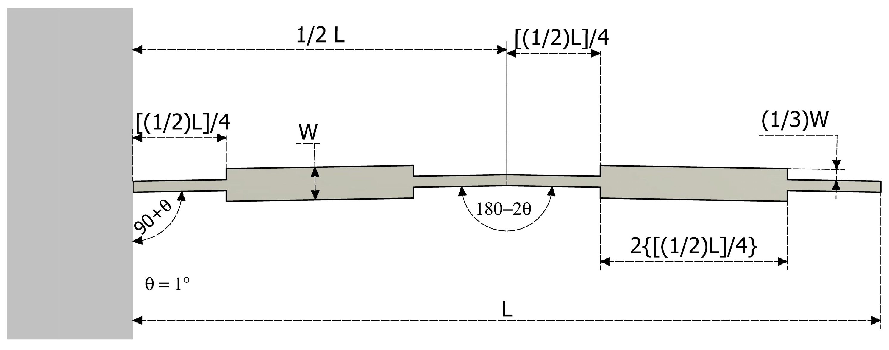
Figure 2) was developed. Proposed modifications were performed in thin arm and flexure, considering an arrangement of mass distribution. A zoom in of the thin beam is shown in
Figure 3, where proportions related to
L, the total length of the modified beam, show the criteria for the length calculation of each segment. In addition, the proportions about the widths are also given.
In all devices under consideration in this work, Polysilicon is used as a structural material with a thickness value of 1.5 µm. It is possible to fabricate all devices presented here using the PolyMUMPS process.
In order to observe the effect of the modified U-shaped actuator, the form of the microgripper is similar to the one presented also in [
2] (
Figure 4).
Next, the mathematical description of the electrical and magnetic properties used in the design of the microgripper is carried out.
The intensity of the electrical current
I can be calculated by using the Equation [
32]:
where
V is the voltage supplied to the device and
R is the resistance that the material opposes to electrical current flow.
The electrical resistance (
R) of a resistor can be determined from the physical dimensions of each device, such as length and area as well as by its inherent electrical properties of the material with which it was manufactured as the electrical resistivity according to the Equation [
32]:
where
ρ is resistivity,
l is the length and
A is the cross-section area, respectively (Ohm law).
The total resistance of each device is calculated in accordance to the number of sections and configuration,
The corresponding electric power can be calculated by Equation (2).
The increment in temperature, caused by the voltage supply, generates an increment in the body’s dimensions. This property is known as thermal deformation and it is mathematically expressed as:
where
α is the thermal expansion coefficient of the corresponding material and
ΔT denotes the temperature change. Room temperature in this paper was considered as 26.85 °C.
The operation frequency was obtained and adapted from [
33] by the mathematical formula
where
E is the Young´s modulus of material,
m is the mass of the system,
t,
w and
l are the thickness, width, and length of the device, respectively.
The stiffness can be calculated using the mathematical expression [
34]:
where
F is the force applied by the tips of the gripper and
ΔYmax represents their maximum deformation.
The mobility of the modified U-shape micro-actuator is calculated using the well-known Gruebler Equation [
35]:
Where L is the number of links, J is the number of full joints and G is the number of grounded links.
In the design of the proposed electromechanical microgripper, several physical properties of the material with which its manufacture is planned should be considered. A summary of the mechanical, electrical and thermal properties involved in the microgripper design is found in
Table 2.
3. Results
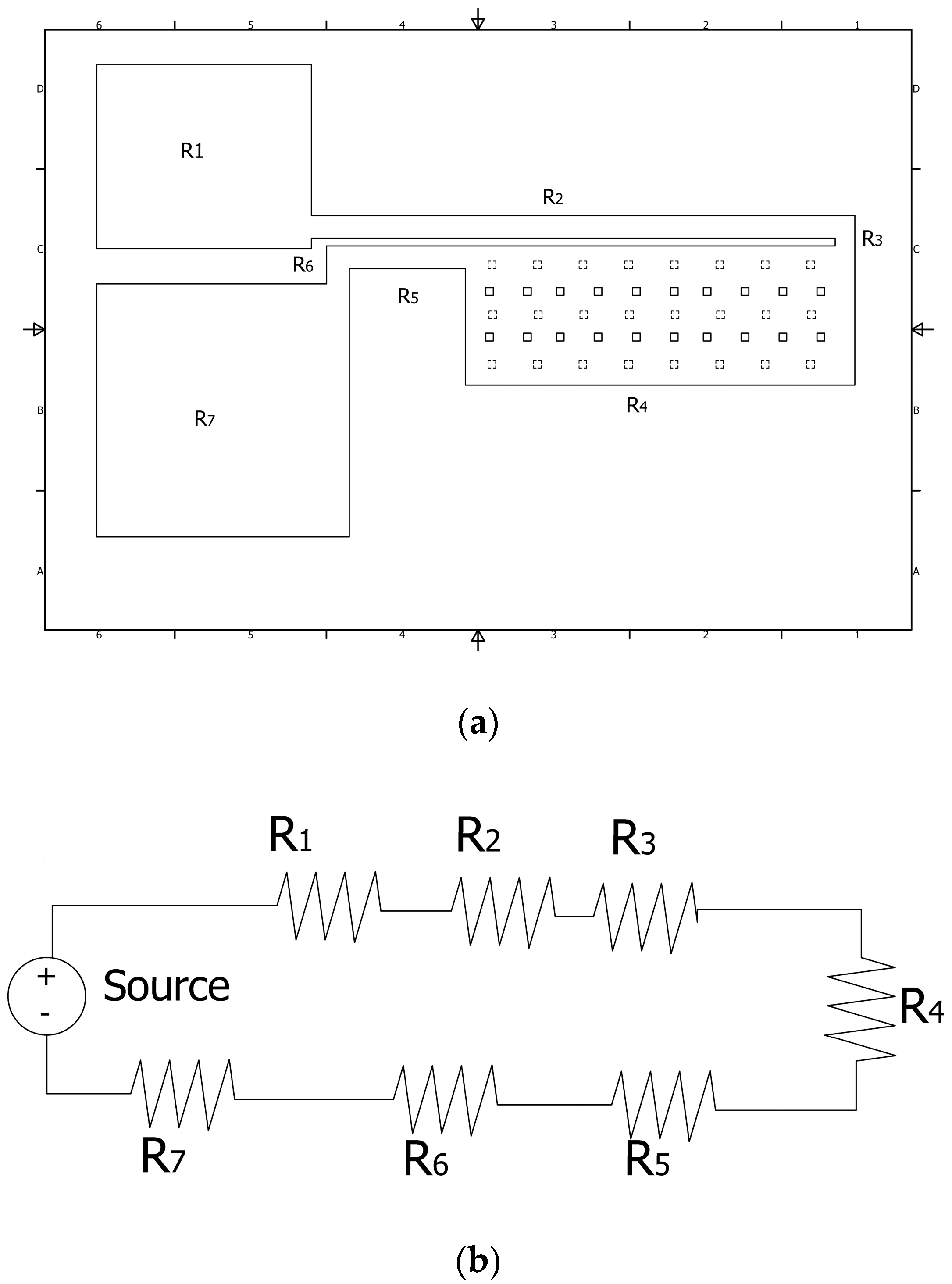
3.1. Results for Initial U-Shaped Actuator
The total electrical resistance
RT is determined as the equivalent resistance of the series connection of the resistors
R1 to
R7, which corresponds to each part of it (
Figure 5). R
T is calculated as:
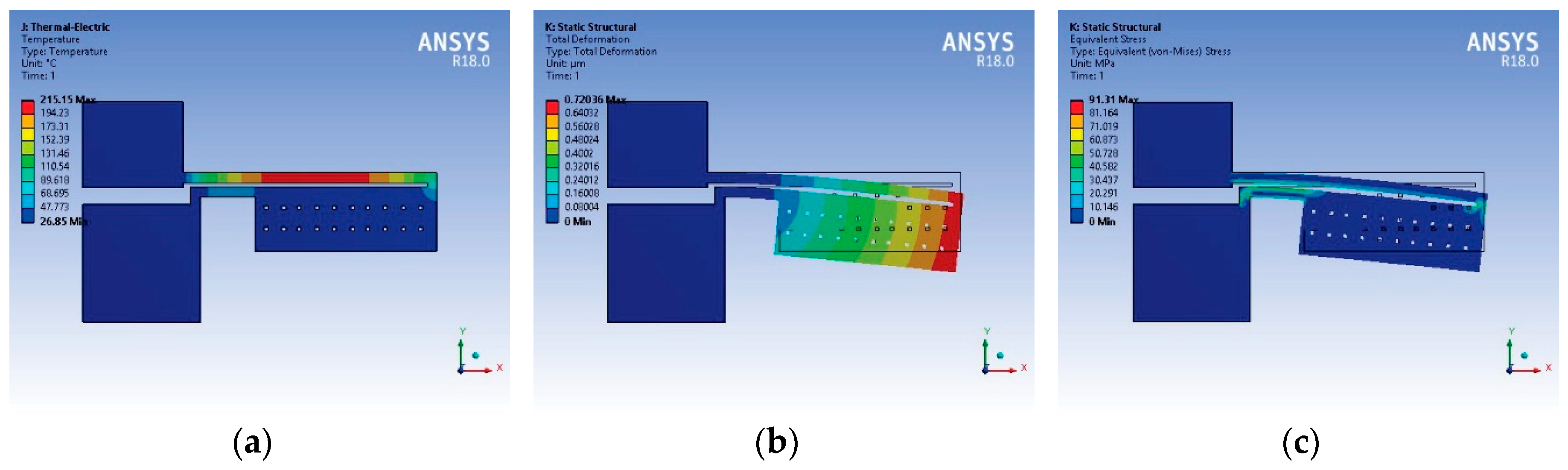
Performance parameters of the initial U-shaped micro-actuator, obtained by simulation, are shown in
Figure 6. A simple approach to characterizing the driving force, and displacement, of Polysilicon U-shaped micro-actuator is provided in [
38].
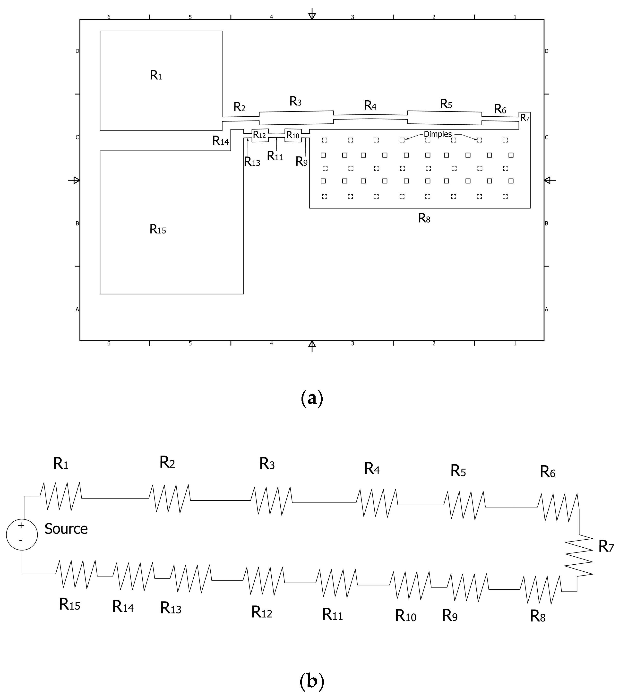
3.2. Results for Modified U-Shaped Actuator
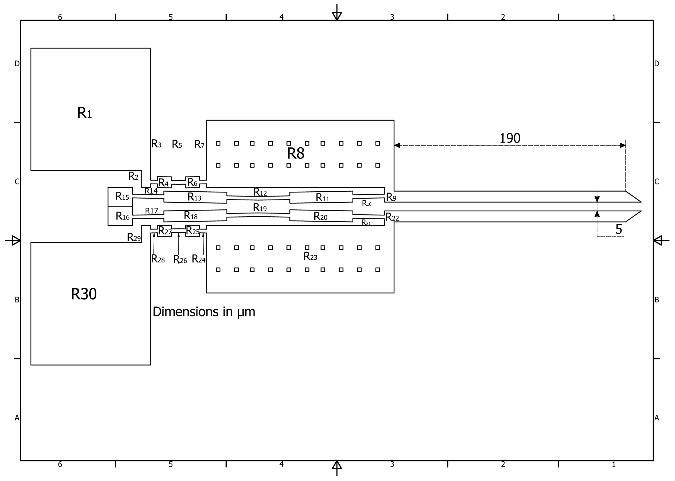
The isometric scheme and resistive electrical model of U-shaped modified actuator is illustrated in
Figure 7.
RT in this case is determined as the equivalent resistance of the series connection of the resistors
R1 to
R15.The mobility of U-shaped micro-actuator is calculated using Equation (7) using the 2G, 5L and 4J (as they can be observed in
Figure 8), given only one DOF.
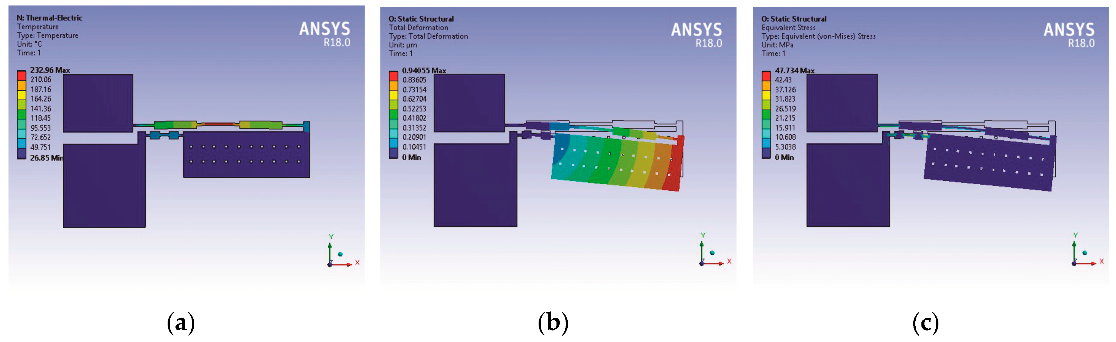
The corresponding performance parameters are shown in
Figure 9.
3.3. Results for Microgripper with Modified U-Shaped Micro-Actuator
The calculation for the case of microgripper based on initial U-shaped actuator is not presented, due to its similarity with the modified case here presented. These results are given in Tables 6 and 7.
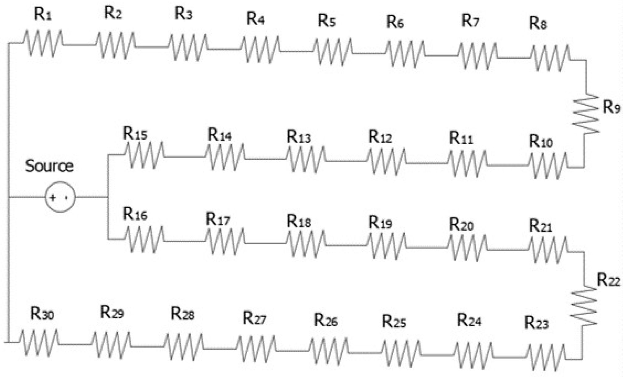
For Microgripper with Modified U-shaped Micro-actuator, the total electrical resistance is calculated as the parallel between the equivalent resistances of each U-shaped actuator [
39], as shown in
Figure 10, and in Equation (9), where it is considered that both sides are equal.
=
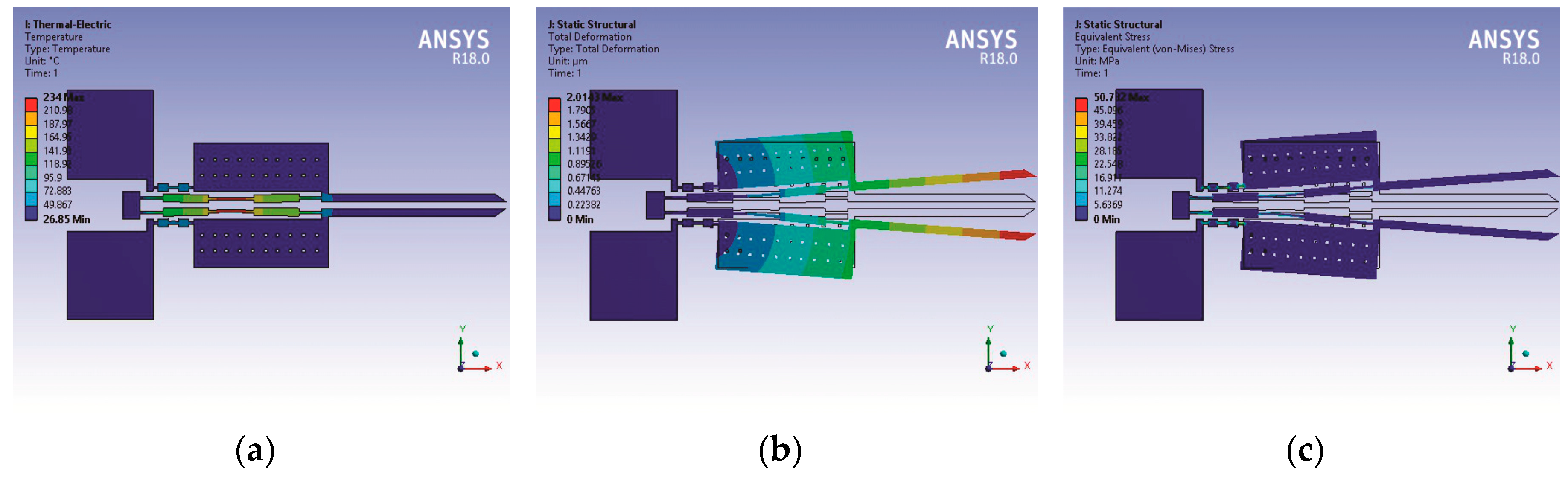
Performance parameters of the microgripper based on modified U-shaped micro-actuator (total deformation, temperature distribution and normal stress) were obtained by simulation (
Figure 11).
4. Discussion
Simulation results for U-shaped actuators and microgrippers were obtained with the following models with ANSYS Workbench: thermal electric, static structural, and modal module. About the mesh characteristics, some differences were considered (see
Table 3).
Three conditions were considered:
Thermal convection is one of the three mechanisms of heat transfer, besides conduction and thermal radiation. The heat is transferred by a moving fluid (e.g., wind or water), and is usually the dominant form of heat transfer in liquids and gases. Convection can be divided into natural convection and forced convection [
40]. Condition number 3, which was considered the rule of thumb, establishes that for dimensions less than 1 mm, there will likely not be any free convective currents [
41]. If the surrounding fluid is a liquid, then the range of the forced heat transfer coefficients are much wider. For free convection in a liquid
is the typical range. For forced convection, the range is even wider
. In this case, air was considered as the fluid.
In
Table 4, total resistance values of the initial and modified U-shaped actuators are given. The values of performance parameters are presented in
Table 5.
In relation to normal stress of initial and modified U-shaped micro-actuators, they can be observed in the corresponding graphs (6c and 9c, respectively). The largest values correspond to all thinnest segments in thin arms and flexures; these values are 91.34 MPa and 47.734 MPa, respectively. The modified U-shaped micro-actuator shows a decrease of 52.25%. Both values are much smaller than the value of the tensile yield strength for Silicon.
Total resistances for initial and modified microgrippers are given in
Table 6.
Table 7 summarizes the values of the performance parameters of the microgrippers under analysis. It is important to point out that only small differences were obtained between the initial model presented here, and those reported values in [
2], but this comparison was not added.
The equivalent stress values for initial and modified microgrippers was 101.6 MPa and 50.732 MPa, respectively, and this was obtained in the same thinnest parts of the hot arms and flexures in the corresponding U-shaped micro-actuators. Again, this stress has a lower value for the case of the modified microgripper in 49.93%.
From
Table 4, it is established that for the case of the U-shaped actuators (initial and modified), the theoretical and simulated values of total resistance are close, since the largest error is 4%. The total resistance of the modified structure is approximately two times, when it is compared with those of the initial structure. In the case of microgrippers based on initial and modified U-shaped micro-actuators, the performance is similar, as it can be seen in
Table 6.
For the case of the performance parameters of the U-shaped actuators, shown in
Table 5, it can be observed that the improvements obtained with modified thin beam and flexure, reside in a displacement increment of 25%, with an increment in temperature at the middle part of the modified part of the thin beam of 8.27%. Equivalent stress, current and force have lower values. From
Table 7, it is possible to deduce that for the case of the microgrippers based on these actuators, they have a similar response. The modified microgripper shows a displacement increment of 22.33%, and an increment in temperature of 10.8% at the middle part of the modified thin beam. Force, current and stress also show notable decrements.
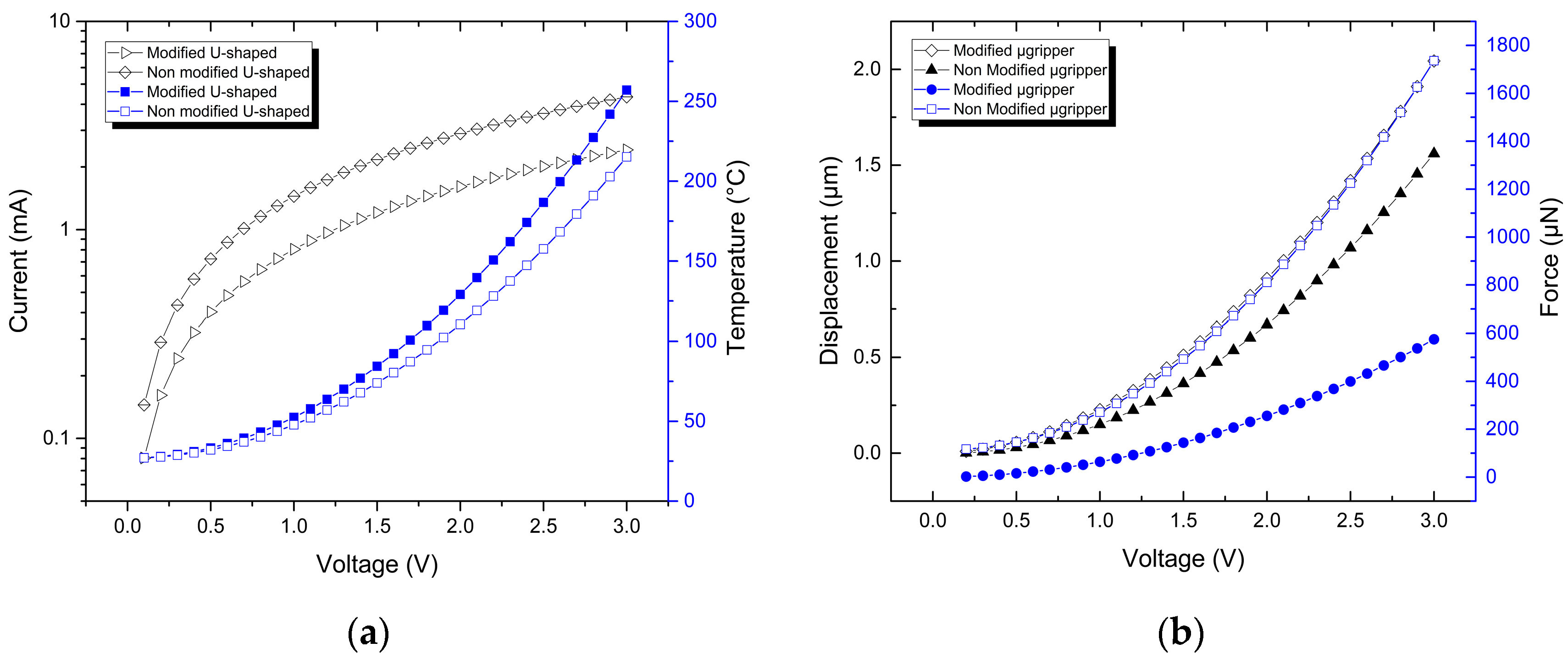
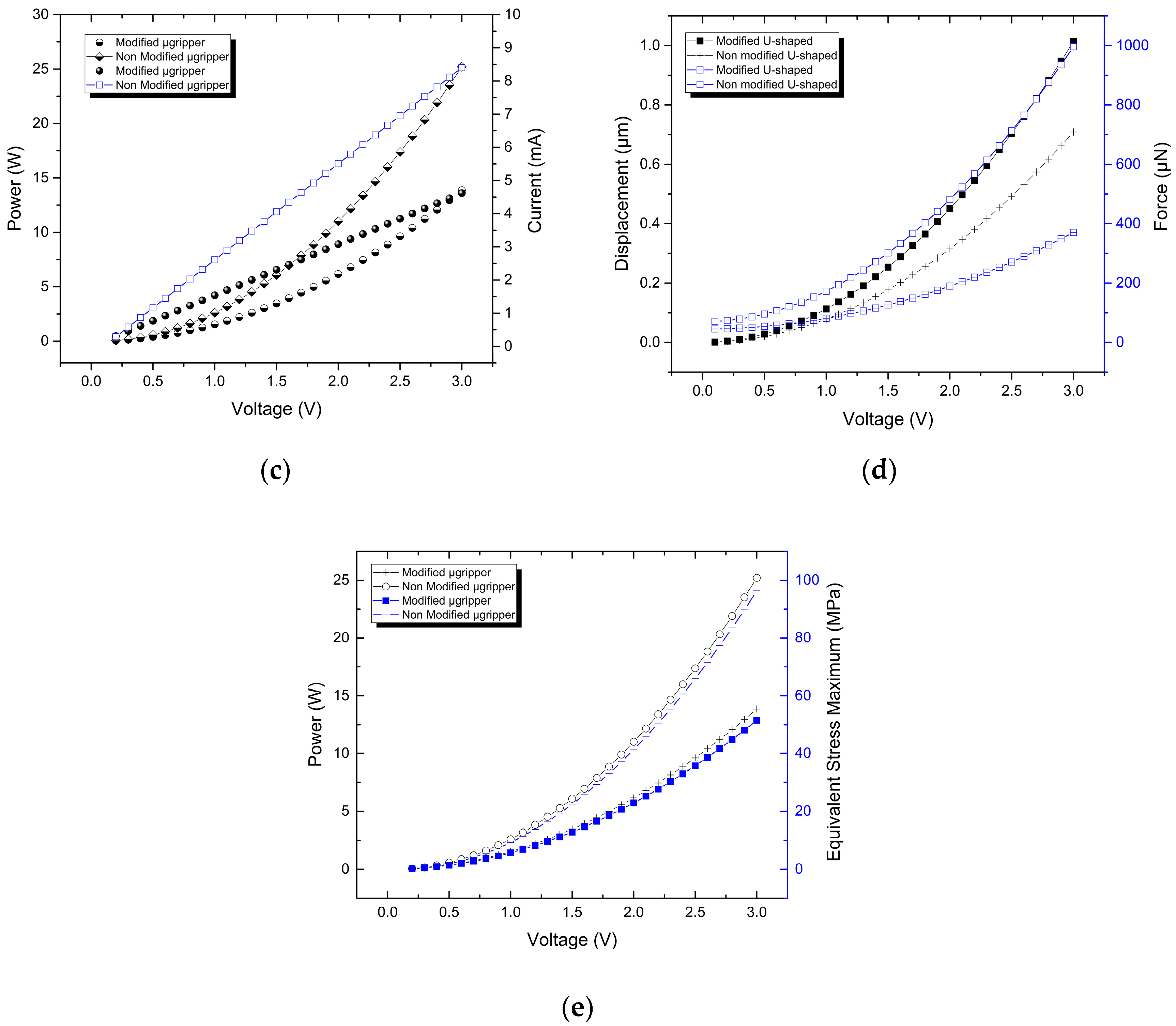
A graphical representation of the performance parameters corresponding to the initial and modified U-shaped micro-actuators and the microgrippers based on them, respectively, was obtained by means of parametric simulation, as shown in
Figure 12. It can be observed that there are similar tendencies between the response of the corresponding initial and modified structures, but the values for the cases of force, current, power and total stress are relatively far.
5. Conclusions
In this paper, a new topology of a U-shaped micro-actuator has been presented on the base of lumped compliant mechanisms, designed by means of a mass distribution applied to thin beam and flexure. Fundamental changes in performance parameters are given on displacement, where an increase of 25% is given, but with a notable decrease in force. A reduction in normal stress of 52.25% is also shown. An analogous response is observed for the case of the microgripper based on this modified actuator. In this case, an increase of 22.33% is obtained, but current, power and stress decrease. Force has also the most notable decrement.
The performance parameters considered as fundamental in the electrothermal performance analysis of the microgripper were displacement, force and normal stress (Equivalent Stress Von-Misses). They were obtained by simulation. In addition, current, power and temperature were also analyzed.
The total resistance values obtained from theoretical calculations and simulation were close, since the maximum difference was 4%. Theoretical values of resistance were used for the calculation of current and power, showing good agreement with the corresponding values obtained by simulation.
For the modified microgripper, the reduction in current and power values favors applications which require low values of these parameters. Its lower clamping force facilitates its use when sensitive objects need to be manipulated.
Author Contributions
P.V.-C.: Simulation, validation, collaboration and microgripper design. M.T.-T.: Conceptualization of research, collaboration in microgripper design, formal analysis, supervision and editing. R.C.-R: Resources, methodology and formal analysis. J.A.R.-R.: Supervision. R.V.-B.: Research, writing review and editing.
Funding
This research was funded by CONACyT, grant number “A1-S-33433”.
Acknowledgments
Pedro Vargas-Chable expresses his sincere gratitude to CONACyT for the scholarships with grant reference 484392.
Conflicts of Interest
The authors declare no conflict of interest.
References
- Leondes, C.T. MEMS/NEMS Handbook: Techniques and Applications; Springer: New York, NY, USA, 2006; Volume 4, ISBN 978-0-387-25786-2. [Google Scholar]
- Cauchi, M.; Grech, I.; Mallia, B.; Mollicone, P.; Sammut, N. Analytical, Numerical and Experimental Study of a Horizontal Electrothermal MEMS Microgripper for the Deformability Characterisation of Human Red Blood Cells. Micromachines 2018, 9, 108. [Google Scholar] [CrossRef]
- Kaźmierski, T.J.; Beeby, S. Energy Harvesting Systems: Principles, Modeling and Applications; Springer: New York, NY, USA, 2011; ISBN 978-1-4419-7566-9. [Google Scholar]
- Chronis, N.; Lee, L.P. Electrothermally Activated SU-8 Microgripper for Single Cell Manipulation in Solution. J. Microelectromech. Syst. 2005, 14, 857–863. [Google Scholar] [CrossRef]
- Solano, B.; Wood, D. Design and Testing of a Polymeric Microgripper for Cell Manipulation. Microelectron. Eng. 2007, 84, 1219–1222. [Google Scholar] [CrossRef]
- Yang, S.; Xu, Q. A Review on Actuation and Sensing Techniques for MEMS-based Microgrippers. J. Micro-Bio Robot. 2017, 3, 1–14. [Google Scholar] [CrossRef]
- Jia, Y.; Jia, M.; Xu, Q. A Dual-Axis Electrostatically Driven MEMS Microgripper. Int. J. Adv. Robot. Syst. 2014, 11, 187. [Google Scholar] [CrossRef] [Green Version]
- Kuo, J.-C.; Huang, H.-W.; Tung, S.-W.; Yang, Y.-J. A Hydrogel-based Intravascular Microgripper Manipulated using Magnetic Fields. Sens. Actuator A-Phys. 2014, 211, 121–130. [Google Scholar] [CrossRef]
- Breger, J.C.; Yoon, C.; Xiao, R.; Kwag, H.R.; Wang, M.O.; Fisher, J.P.; Nguyen, T.D.; Gracias, D.H. Self-Folding Thermo-Magnetically Responsive Soft Microgrippers. ACS Appl. Mater. Interfaces 2015, 7, 3398–3405. [Google Scholar] [CrossRef] [PubMed]
- Piriyanont, B.; Moheimani, S.O.R. MEMS Rotary Microgripper with Integrated Electrothermal Force Sensor. J. Microelectromech. Syst. 2014, 23, 1249–1251. [Google Scholar] [CrossRef]
- Daunton, R.; Gallant, A.; Wood, D.; Kataky, R. A Thermally Actuated Microgripper as an Electrochemical Sensor with the Ability to Manipulate Single Cells. Chem. Commun. 2011, 47, 6446–6448. [Google Scholar] [CrossRef] [PubMed]
- Shi, H.; Shi, W.; Zhang, R.; Zhai, J.; Chu, J.; Dong, S. A Micromachined Piezoelectric Microgripper for Manipulation of Micro/Nanomaterials. Rev. Sci. Instrum. 2007, 88, 065002. [Google Scholar] [CrossRef]
- Jia, Y.; Xu, Q. MEMS Microgripper Actuators and Sensors: The State-of-the-Art Survey. Recent Pat. Mech. Eng. 2013, 6, 132–142. [Google Scholar] [CrossRef]
- Chen, B.K.; Zhang, Y.; Perovic, D.D.; Sun, Y. MEMS Microgrippers with Thin Gripping Tips. J. Micromech. Microeng. 2011, 21, 105004. [Google Scholar] [CrossRef]
- Park, D.S.-W.; Nallani, A.K.; Cha, D.; Lee, G.-S.; Kim, M.J.; Skidmore, G.; Lee, J.-B.; Lee, J-S. A Sub-Micron Metallic Electrothermal Gripper. Microsyst. Technol. 2010, 16, 367–373. [Google Scholar] [CrossRef]
- Pranonsatit, S.; Holmes, A.S.; Robertson, I.D.; Lucyszyn, S. Single-Pole Eight-Throw RF MEMS Rotary Switch. J. Microelectromech. Syst. 2006, 15, 1735–1744. [Google Scholar] [CrossRef]
- Iamoni, S.; Soma, A. Design of an Electro-Thermally Actuated Cell Microgripper; Springer: Berlin/Heidelberg, Germany, 2014. [Google Scholar]
- Chu, J.; Zhang, R.; Chen, Z. A Novel SU-8 Electrothermal Microgripper based on the Type Synthesis of the Kinematic Chain Method and the Stiffness Matrix Method. J. Micromech. Microeng. 2011, 21, 1–15. [Google Scholar] [CrossRef]
- Seidemann, V.; Bütefisch, S.; Büttgenbach, S. Fabrication and Investigation of In-Plane Compliant SU8 Structures for MEMS and Their Application to Micro Valves and Micro Grippers. Sens. Actuators 2002, 97–98, 457–461. [Google Scholar] [CrossRef]
- Tsai, Y.C.; Lei, S.H.; Sudin, H. Design and Analysis of Planar Compliant Microgripper based on Kinematic Approach. J. Micromech. Microeng. 2005, 15, 143–156. [Google Scholar] [CrossRef]
- Kim, K.; Liu, X.; Zhang, Y.; Sun, Y. Nanonewton Force-Controlled Manipulation of Biological Cells using a Monolithic MEMS Microgripper with Two-Axis Force Feedback. J. Micromech. Microeng. 2008, 18, 1–8. [Google Scholar] [CrossRef]
- Jia, Y.; Xu, Q. Design of a Monolithic Dual Axis Electrostatic Actuation MEMS Microgripper with Capacitive Position/Force Sensors. In Proceedings of the IEEE International Conference on Nanotechnology, Beijing, China, 5–8 August 2013; pp. 817–820. [Google Scholar]
- Mackay, R.E.; Le, H. Development of Micro-Tweezers for Tissue Micro-Manipulation. In Proceedings of the 2008 2nd International Conference on Bioinformatics and Biomedical Engineering, Shangai, China, 16–18 May 2008; pp. 1551–1555. [Google Scholar]
- Feng, Y.Y.; Chen, S.-J.; Hsieh, P.-H. Fabrication of an Electro-Thermal Micro Gripper using Silver-Nickel Ink. In Proceedings of the IEEE 29th International Conference on Micro Electro Mechanical Systems (MEMS), Shangai, China, 28 July 2016. [Google Scholar]
- Bazaz, S.A.; Khan, F.; Shakoor, R.I. Design, Simulation and Testing of Electrostatic SOI MUMPs based Microgripper. Sens. Actuator A-Phys. 2011, 167, 44–53. [Google Scholar] [CrossRef]
- Shivhare, P.; Uma, G.; Umapathy, M. Design Enhancement of a Chevron Electrothermally Actuated. Microsyst. Technol. 2015, 22, 2623–2631. [Google Scholar] [CrossRef]
- Velosa-Moncada, L.; Aguilera-Cortés, L.A.; González-Palacios, M.; Raskin, J.-P.; Herrera-May, A.L. Design of a Novel MEMS Microgripper with Rotatory Electrostatic Comb-Drive Actuators for Biomedical Applications. Sensors 2018, 18, 1664. [Google Scholar] [CrossRef]
- Fu, Y.; Du, H. Fabrication of micromachined TiNi based microgripper with compliant structure. Proc. SPIE 2003. [Google Scholar] [CrossRef]
- Verotti, M.; Dochshanov, A.; Belfiore, N. A Comprehensive Survey on Microgrippers Design: Mechanical Structure. J. Mech. Des. 2017, 139, 1–26. [Google Scholar] [CrossRef]
- Stolarski, T.; Nakasone, Y.; Yoshimoto, S. Engineering Analysis with ANSYS Software; Butterworth-Heinemann: Oxford, UK, 2006; ISBN 0-7506-6875-X. [Google Scholar]
- Feng, Y.Y.; Chen, S.J.; Hsieh, P.H.; Chu, W.T. Fabrication of an Electro-Thermal Micro-Gripper with Elliptical Cross-Sections using Silver-Nickel Composite Ink. Sens. Actuator A-Phys. 2016, 245, 106–112. [Google Scholar] [CrossRef]
- Askeland, D.R.; Wright, W.J. The Science and Engineering of Materials, 7th ed.; Cengage Learning: Boston, MA, USA, 2016; ISBN 978-1-350-07676-1. [Google Scholar]
- Cabello-Ruiz, R.; Tecpoyotl-Torres, M.; Torres-Jacome, A.; Grimalsky, V.; Vera-Dimas, J.G.; Vargas-Chable, P. A Novel Deformation-Amplifying Compliant Mechanism Implemented on a Modified Capacitive Accelerometer. Int. J. Electr. Comput. Eng. 2017, 7, 1858–1866. [Google Scholar] [CrossRef]
- Johnstone, R.W.; Parameswaran, M. Modelling Surface-Micromachined Electrothermal Actuators. Can. J. Elect. Comput. Eng. 2004, 29, 193–202. [Google Scholar] [CrossRef]
- Abu-Zarifa, A. Theory of Machines. Islamic University of Gaza. Department of Mechanical Engineering. 2012. Available online: http://site.iugaza.edu.ps/wp-content/uploads/file/IUGAZA%20TOM2012_CH1-2.pdf (accessed on 4 March 2019).
- Ghodssi, R.; Lin, P. MEMS Materials and Processes Handbook; Springer: New York, NY, USA, 2011; ISBN 978-0-387-47318-5. [Google Scholar]
- Sharpe, N.J.; Yuan, B.; Vaidyanathan, R.; Edwards, R.L. Measurements of Young’s Modulus, Poisson’s Ratio, and Tensile Strength of Polysilicon. In Proceedings of the Tenth IEEE International Workshop on Microelectromechanical Systems, Nagoya, Japan, 26–30 January 1997. [Google Scholar]
- Huang, Q.A.; Leer, N.K. A simple approach to characterizing the driving force of polysilicon laterally driven thermal microactuators. Sens. Actuators 2000, 80, 267–272. [Google Scholar] [CrossRef]
- Nilsson, J.W.; Riedel, S.A. Electric Circuits, 10th ed.; Pearson: Harlow, UK, 2015; ISBN 978-0-13-376003-3. [Google Scholar]
- Green TEG AG. Convective Heat Flux Explained. Zürich, Switzerland. Available online: https://www.greenteg.com/template/userfiles/files/Convective%20Heat%20Flux%20Explained.pdf (accessed on 18 February 2019).
- Modeling Natural and Forced Convection in COMSOL Multiphysics®. Available online: https://www.comsol.com/blogs/modeling-natural-and-forced-convection-in-comsol-multiphysics/ (accessed on 4 March 2019).
Figure 1.
Geometry and dimensions of the initial U-shaped micro-actuator, based in [
2].
Figure 1.
Geometry and dimensions of the initial U-shaped micro-actuator, based in [
2].
Figure 2.
Geometry with dimensions of the proposed modified U-shaped micro-actuator.
Figure 2.
Geometry with dimensions of the proposed modified U-shaped micro-actuator.
Figure 3.
Geometry of the thin beam with distributed mass.
Figure 3.
Geometry of the thin beam with distributed mass.
Figure 4.
Microgripper based on the modified U-shaped micro-actuator of
Figure 2. Dimensions of the jaws are shown.
Figure 4.
Microgripper based on the modified U-shaped micro-actuator of
Figure 2. Dimensions of the jaws are shown.
Figure 5.
Initial U-shaped actuator: (a) Isometric scheme and (b) Resistive model.
Figure 5.
Initial U-shaped actuator: (a) Isometric scheme and (b) Resistive model.
Figure 6.
Performance parameters of the Polysilicon U-shaped micro-actuator: (a) temperature distribution (b) total deformation, and (c) normal stress.
Figure 6.
Performance parameters of the Polysilicon U-shaped micro-actuator: (a) temperature distribution (b) total deformation, and (c) normal stress.
Figure 7.
Modified U-shaped micro-actuator: (a) Isometric scheme and (b) resistive model.
Figure 7.
Modified U-shaped micro-actuator: (a) Isometric scheme and (b) resistive model.
Figure 8.
Modified U-shape with Grounds, Links and Joints.
Figure 8.
Modified U-shape with Grounds, Links and Joints.
Figure 9.
Performance parameters of the Polysilicon modified U-shaped micro-actuator: (a) temperature distribution (b) total deformation, and (c) normal stress.
Figure 9.
Performance parameters of the Polysilicon modified U-shaped micro-actuator: (a) temperature distribution (b) total deformation, and (c) normal stress.
Figure 10.
Electrical resistance model for the microgripper based on modified U-shaped micro-actuator.
Figure 10.
Electrical resistance model for the microgripper based on modified U-shaped micro-actuator.
Figure 11.
Performance parameters of the Polysilicon microgripper based on Modified U-shaped micro-actuator: (a) temperature distribution, (b) total deformation, (and (c) normal stress.
Figure 11.
Performance parameters of the Polysilicon microgripper based on Modified U-shaped micro-actuator: (a) temperature distribution, (b) total deformation, (and (c) normal stress.
Figure 12.
For U-shaped micro-actuators: (a) current and temperature distribution versus applied voltage, (b) displacement and force versus applied voltage. For microgrippers: (c) current and power versus applied voltage, (d) displacement and force versus applied voltage; and (e) equivalent stress versus applied voltage.
Table 1.
State of the art of advances in microgrippers.
Table 1.
State of the art of advances in microgrippers.
| Description | Displacement or Opening (μm) | Force (μN) | Dimensions (μm) | Material | Feeding | Ref. |
|---|
| Electrostatic microgripper with capacitive force sensor. | 70.88 | 190 | ~6900 × 6500 × 500 | Silicon | 120 V | [7] |
| Thermally actuated polymeric microgripper with bare gold working electrode. | 50–150 | N/A | 1500 × 100 × 50 | SU-8/Gold | 2 V | [11] |
| Microgripper with 6 degrees of freedom. | 5 | N/A | 17000 × 5000 × 150 | SU-8/PZT | 10 V | [12] |
| Electrothermal microgripper with chevron micro-actuator. | 1.39 | N/A | ~102 × 35 × 1 | Nickel | 28 mA | [15] |
| Microgripper with chevron micro-actuator rotated at 90°. | 42 | N/A | ~772 × 350 × 10 | Silicon | 100 mW | [16] |
| Microgripper for cell manipulation. | 37 | N/A | ~1000 × 80 × 7 | SU-8/Gold | 45 V | [17] |
| Microgrippers driven by a chevron electrothermal actuator. | 80 | ~200 | 2900 × 3500 × 45 | SU-8 | 53 mV | [18] |
| Pneumatically operated microgripper. | 120 | 10000 | 75000 × 10,000 × 360 | SU-8-SMA | 400 mbar | [19] |
| Optimization of the compliant elements of a Microgripper. | 40 | N/A | ~ 6000 × 1000 × 100 | Polysilicon | 3 V | [20] |
| Microgripper with controlled force. | 67 | 0.0385 | N/A | Silicon | 10 V | [21] |
| Electrostatic microgripper with capacitive force sensor. | 70 | 190 | ~1125 × 900 × 50 | Silicon | 120 V | [22] |
| Microgripper for tissues. | 14.2–40.8 | | 2000 × 2000 × 80 | Silicon | 1.5–3 V | [23] |
| 30.8–153.4 | | Nickel | 0.05–0.2 V |
| Electrothermal microgripper. | 310.6 | N/A | ~13500 × 2500 × 180 | Silver/Ni-ckel | 0.26 A | [24] |
| Electrostatic microgripper with capacitive sensor. | 17 | N/A | 5003 × 6500 × 25 | Silicon | 50 V | [25] |
| Microgripper design using two in-plane chevron electrothermal actuators, in Polysilicon. | 19.2 | 37000 | ~ 870 × 200 × 10 | Polysilicon | 0-1.2 V | [26] |
| Microgripper with rotating element for biomedical applications. | 40 | N/A | 3860 × 50 × 7 | Polysilicon | 23.4–129.2 V with freq. of 463.8 Hz | [27] |
| TiNi film based micro-gripper with compliant structure. | 200 | N/A | ~4500 × 200 × 150 | TiNi | 100 °C | [28] |
Table 2.
Electrical, thermal and mechanical properties of the structural materials used in microgrippers.
Table 2.
Electrical, thermal and mechanical properties of the structural materials used in microgrippers.
| Parameters | Polysilicon [36,37] |
|---|
| Density, ρ [kg/m3] | 2230 |
| Young’s Modulus, E [GPa] | 158 |
| Thermal expansion coefficient, α [1/°C] | 2.8E-6 |
| Isotropic thermal conductivity, k [W/m °C] | 32 |
| Poisson Ratio, ν [Dimensionless] | 0.22 |
| Specific Heat, Cp [J/kg °C] | 712 |
| Electrical Resistivity, ρ [Ω m] | 3.3E-5 |
| Melting point, [°C] | 1411.85 |
| Tensile Yield strength [GPa] | 1.2 |
Table 3.
Considerations of mesh in ANSYS Workbench.
Table 3.
Considerations of mesh in ANSYS Workbench.
| Microgripper | Mesh | Elements | Physics Preference |
|---|
| With initial U-shaped actuator | Refinement with relevance = 100 | 61212 | Mechanical |
| With modified U-shaped actuator | Refinement with relevance = 100 | 27436 | Mechanical |
Table 4.
Total electrical resistance values of the initial and modified U-shaped micro-actuators.
Table 4.
Total electrical resistance values of the initial and modified U-shaped micro-actuators.
| U-Shaped Structure | Theoretical RT [Ω] | Simulated RT [Ω] | % Error |
|---|
| Initial | 686.87 | 691.24 | 0.63 |
| Modified | 1351.35 | 1299.77 | 3.96 |
| % Increment | 50.82 | 53.21 | |
Table 5.
Values of the performance parameters of U-shaped micro-actuators.
Table 5.
Values of the performance parameters of U-shaped micro-actuators.
| U-Shaped Structure | Total Deformation [µm] | Force [µN] | Max. Temp. in Thin Arm [°C] | Natural Frequency [MHz] | Electrical Current [mA] | Power [mW] |
|---|
| Initial | 0.72036 | 996.05 | 215.15 | 275.65 | 4.34 | 13.02 |
| Modified | 0.90455 | 300.08 | 232.96 | 261.36 | 2.3081 | 6.92 |
| % Increment | 25 | −230.12 | 8.27 | −5.184 | −88.69 | −88.15 |
Table 6.
Total resistance values of the microgrippers based on initial and modified micro-actuators.
Table 6.
Total resistance values of the microgrippers based on initial and modified micro-actuators.
| Microgripper | Theoretical RT [Ω] | Simulated RT [Ω] | % Error |
|---|
| With initial U-shaped micro-actuator | 343.44 | 345.19 | 0.5 |
| With Modified U-shaped micro-actuator | 675.675 | 649.51 | 4 |
| % Increase | 50.82 | 53.14 | |
Table 7.
Values of the performance parameters of microgripper based on initial and modified U-shaped micro-actuator.
Table 7.
Values of the performance parameters of microgripper based on initial and modified U-shaped micro-actuator.
| Microgripper | Total Deformation [µm] | Force [mN] | Max. Temp. in Thin Arm [°C] | Natural Frequency [KHz] | Electrical Current [mA] | Power [mW] |
|---|
| With Initial U-shaped actuator | 1.6466 | 1.825 | 211.19 | 16.7 | 8.691 | 26.07 |
| With Modified U-shaped actuator | 2.0143 | 0.567 | 234 | 12.323 | 4.619 | 13.85 |
| % Increment | 22.33 | −321.86 | 10.8 | −26.2 | −53.146 | −53.126 |
© 2019 by the authors. Licensee MDPI, Basel, Switzerland. This article is an open access article distributed under the terms and conditions of the Creative Commons Attribution (CC BY) license (http://creativecommons.org/licenses/by/4.0/).

 ,
, 


