High-Bending-Stiffness Connector (HBSC) and High-Authority Piezoelectric Actuator (HAPA) Made of Such

1
Department of Mechanical Engineering, National University of Singapore, 21 Lower Kent Ridge Road, Singapore 119077, Singapore
2
Microfine Materials Technologies Pte Ltd., 10 Bukit Batok Crescent, The Spire #06-02, Singapore 658079, Singapore
3
Beijing Crystal Valley Technology Co., Ltd., Room B101, Zhongguancum Dongsheng Technology Park, No. 66, Xixiaokou Road, Haidian District, Beijing 100192, China
*
Authors to whom correspondence should be addressed.
Actuators 2018, 7(3), 61; https://doi.org/10.3390/act7030061
Submission received: 30 July 2018
/
Revised: 10 September 2018
/
Accepted: 10 September 2018
/
Published: 12 September 2018
(This article belongs to the Special Issue Piezoelectric Actuators 2018)
Abstract
:High-authority piezoelectric actuator (HAPA) is a term used to describe high-performance piezoelectric actuators of relatively large displacement (≥50 μm) and high blocking force (≥100 N), but compact in size. One such piezoelectric actuator is described in this paper, which is made possible by means of high-bending-stiffness connector (HBSC) that connects multiple commercial piezoceramic stacks into a stable 2- (or multi-) level actuation configuration. Key design requirements for the HBSC are described. Computer simulation results and experimental verification are presented. A HAPA-(2 + 2) actuator was fabricated from such a HBSC, in which there are two commercial PZT stacks projecting upwards in the upper level and two projecting downwards in the lower lever, all of 5 × 5 mm2 in cross-section and 40 mm in length. The HAPA-(2 + 2) actuator prototype displays about twice the overall stroke and blocking force of individual stacks, being about 90 μm and >1600 N, respectively. This compares favorably with lever-arm, flextensional, and telescopic actuators, of which the blocking force is adversely affected. Using a similar concept, HBSCs and HAPAs of other designs are presented. In addition to being stand-alone actuators, the HAPAs can be used as the active material to drive existing displacement amplification schemes to produce piezoelectric actuators of exceptional performance characteristics.
1. Introduction
High-authority piezoelectric actuator is a term used to describe compact, high-performance piezoelectric actuators of relatively large displacement and high blocking force (say, stroke ≥50 μm and blocking force ≥100 N) [1,2]. Such actuators are needed in many technological applications, including industrial, aerospace, defence, medical, and scientific [3].
Direct push-pull piezoelectric actuators include longitudinal (d33) mode multilayer stacks and transverse (d31) mode tube actuators made of piezoceramics, notably lead zirconate titanate (PZT) ceramics. They are extensively used to-date. However, while piezoceramic stacks are of large blocking force of >500 N, both types of actuator display low axial displacement of <40 µm typically.
Over the decades, various displacement enhancement schemes have been devised to increase the axial displacement of piezoceramic stacks including lever-arm, flextensional, meander-line and telescopic approaches. Lever-arm actuators utilize the lever mechanism to increase the displacement of piezoceramic stacks [4,5,6]. Flextensional actuators comprise a group of actuators in which the motion generated by a piezoceramic stack is converted to a much larger displacement in the transverse direction by means of an elastic flextensional member [7,8], the latter being made of metal typically. They include the oval [9], bow [10], moonie, and cymbal [11,12] actuators. Moonie and cymbal actuators consist of a piezoceramic disk sandwiched by two metallic end caps. Radial displacement of the disk flexes the end caps, producing much enhanced displacement in the axial direction. For both lever-arm and flextensional actuators, the blocking force of the resultant device is reduced accordingly despite the enhanced displacement [4,5,6,9,10,11,12]
Another interesting displacement enhancement scheme is the meander-line approach [13]. The scheme utilizes two symmetrical sets of push-pull mode rectangular piezoceramic bars. The piezoceramic bars in each set are connected with metallic connectors into a meander-line configuration. Electrically, they are so connected such that as one bar extends, the adjacent bar contracts, and vice versa. All of the PZT bars in each set work in unison and contribute to the overall displacement of the device. A total of 22 bars were used in the prototype actuator fabricated, which measured about 135 mm (L) × 6.2 mm (H) × 37.5 mm (D) in dimensions. Experimental results showed that the fabricated meander-line actuator displayed about 100 µm overall displacement in the 37.5 mm (D) direction at 0.67 kV/mm (i.e., 1000 V over 1.5 mm PZT bar thickness). However, due to the large moment arm inherent in such a design, it displayed a low blocking force of <1 N (even with additional stiffening features). Such a design is therefore not suitable for high load application.
Telescopic actuators had been developed and evaluated by a number of researchers [1,2,14]. In such a design, concentric piezoelectric tubes were assembled and connected in a meander-line arrangement, such that as one piezoelectric tube expands, its adjacent tube will contract and vice versa, and all of the tubes work in unison to produce the overall displacement of the device. For the 3-cylinder telescopic actuators fabricated by Alexander and Brei [14], measuring about 26 mm in outer diameter and 80 mm in height, a stroke of up to 28 µm at 300 V (PZT tube thickness being 1.0–1.2 mm), and a reasonably high blocking force of 250−275 N were achieved.
It is evident from the above descriptions that while various schemes are available to-date to increase the axial displacement of piezoceramic stacks or tubes, due to the compliant nature of the displacement amplifiers or mechanical connectors, the blocking forces of the resultant devices are adversely affected as a result, being several times to an order of magnitude smaller when compared with that of an individual stack. Furthermore, although not reported by the authors, the telescopic actuators, when molded or cast out as a single-piece ceramic structure, would be fragile due to the unavoidable local bending in the structure during operation and the brittle nature of PZT ceramics.
2. Design Concept of High-Bending-Stiffness Connector (HBSC) and Resultant High-Authority Piezoelectric Actuator (HAPA)
The main objective of the present work is to develop a mechanical connector-cum-housing, such that it can be used to house multiple units of piezoelectric stacks, and, in so doing, displays double (or triple) the displacement of an individual stack without jeopardizing the blocking force. Such a connector should possess high bending stiffness, i.e., it should display limited bending deflection during operation which in effect counters the axial displacement of the resultant device. Such connectors are hereafter referred to as High-Bending-Stiffness Connector, or HBSC for short.
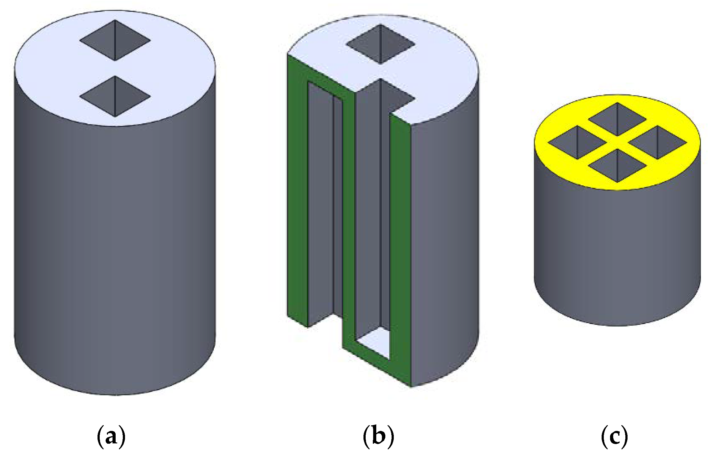
In its simplest form, the HBSC concerned consists of a solid cylindrical block into which two identical sets of interspersing recesses for housing piezoceramic stacks are machined from both end faces, one set having their openings sited at the top end face of the connector body and the other set at the bottom end face. Figure 1a illustrates such a (2 + 2)-HBSC with four square cross-sectioned recesses. Here, “2 + 2” implies that two (2) of the four recesses have their openings at the top end face and the other two (2) have their openings at the bottom end face. Figure 1b shows a longitudinal section (in green), while Figure 1c the cross-section (in yellow) of the HBSC, illustrating the detailed configuration of the four recesses.
Preferably, the solid cylindrical block is made of metal, such that the recess housings can be machined out readily, as shown in Figure 1. The recess housings are of a suitable cross-section having bore dimensions slightly larger than the cross-section of the stack actuator housed in it. Each recess is meant for housing an active element, which can be a piezoceramic stack or any suitable push-pull mode piezoelectric actuator. Figure 2a shows how the four stack actuators (in blue) are inserted into the HBSC. They are secured by bonding them onto the recess bases via epoxy. Figure 2b shows a schematic of a completed (2 + 2)-2-level (2×-) actuator, including the bonded top and bottom end caps (except the wiring, which is not shown for clarify sake).
The working principle of the resultant actuator is quite straight forward. Under the same applied voltage, each piezoceramic stack will extend by a fixed displacement ΔL. In the said design, the two interspersing pairs of piezoceramic stack work in unison to displace both end caps along the axis of the connector. Hence, if the bottom end cap is fixed on a rigid table, the top end cap will extend approximately by 2 × ΔL−ΔLHBSC, where ΔLHBSC is the equivalent axial displacement of the HBSC due to the fact that the recess base would undergo bending deflection during loading. For a highly rigid two-level connector, ΔLHBSC << 2 × ΔL. The overall stroke of the resultant actuator is thus about 2 × ΔL, while its overall length is only fractionally larger than that of a piezoceramic stack.
Since the blocking force of the device is proportional to the overall stack cross-sectional area, the resultant (2 + 2)-actuator will have about 2× the blocking force of an individual piezoceramic stack. Thus, despite its compactness in height, the said device exhibits approximately twice the axial displacement and blocking force. They are hereafter referred to as High-Authority Piezoelectric Actuator, or HAPA for short.
To achieve the above goal, the following unique features must be realized for the design of the HBSC [15]: (1) the interspersing recess housings are arranged circumferentially, as opposed to radially in the earlier works [1,2,13,14]. This is to ensure that all of the stacks have equal and/or reduced moment arms about the central axis of the device; (2) the cross-section of the recess housings should be as close as possible to that of the active element to minimize the load span at their bases; (3) the base of the recesses should be firmly connected to the main body of the connector to eliminate possible cantilever effect; and preferably, (4) the connector also has a relatively thick outer ring or shell to further minimize the bending displacement.
It should be stressed that although similar in appearance, the 2-level HAPA actuator described in this work is a different type of actuator from the three-cylinder telescopic actuator described earlier for the following reasons. (1) In a two-level HAPA, there is no middle PZT cylinder as in a three-cylinder telescopic actuator. This particular PZT tube is under tension in the presence of any pre-load or added load. In the HAPA, the strong and tough unmachined part of the metallic HBSC body is the intermediate layer. As such, all of the stacks in the HAPA are placed under compression during use. (2) In the telescopic actuator, the PZT tubes are disposed radially, giving rise to long moment arms about the actuator central axis, especially for those outer-most tubes. In HAPA, the PZT stacks are disposed circumferentially, hence having equal and/or reduced moment arms about the actuator axis. (3) In HAPA, the cross-section of the recesses in the HBSC is kept close to that of the stack and the recess base is firmly connected to the unmachined HBSC body, the latter being made of strong and tough metal. In contrast, in telescopic actuator, the metallic connectors are unsupported. They are thus relatively compliant under bending during operation. Bending of the connectors not only off-sets the axial displacement of the actuator, but also places the associated epoxy joints and the adjacent PZT ceramic material under large bending stresses. This remains so even if the telescopic actuator is molded or cast out as a single-piece device. These locations are thus the weakest links of the telescopic design. In HAPA, most of the bending is taken up by the strong and tough recess bases of the metallic HBSC, such that the PZT stacks are placed under compression exerted by the pre-load and/or the added load during operation. All of the above features contribute concertedly to the large stroke and high blocking force of the HAPA, as will be shown below.
Based on the above design concept, beside (2 + 2)-HBSC with square cross-sectioned recesses described above, other similar designs like (2 + 2)-HBSC with circular cross-sectioned recesses, (3 + 3)-HBSC with square or circular cross-sectioned recesses, etc., are also possible [15]. In this work, we shall focus on the (2 + 2)-HBSCs with square and circular cross-sectioned recesses and HAPA actuators made of them.
3. Computer Simulation Study on Deformation of HBSC under Load
During operation of a HAPA actuator, the bases of the recesses in the HBSC will deflect under load, causing the overall axial displacement of the HAPA to reduce accordingly. The deflection deformation of the recess base of HBSCs under load was estimated by means of computer simulation. In the present work, the simulation was done using the SolidWorks software (Dassault Systems, SolidWorks 2016 SimulationXpress Analysis Wizard, Velizy-Villacoublay, France).
In the first simulation model, the object is a (2 + 2)-HBSC with square cross-sectioned recesses. The outer dimensions of the HBSC are 22 mm in diameter and 40 mm in height. The four recesses, each measuring 5.5 × 5.5 mm2 in cross-section and 38 mm in depth, are disposed at 10.6 mm P.C.D. at equal angular separation in a two-up and two-down configuration. The base of each recess is thus 2.5 mm thick, which is the unmachined part of the connector body, and hence firmly connected to the latter.
In the simulation, only half of the HBSC was modelled. This is because due to symmetry, the mid cross-sectional plane (marked in blue in Figure 1) of the HBSC will remain relatively undeformed during axial loading of the HAPA. This mid plane, marked blue in Figure 3a, is taken as the undeformed reference surface. The red surfaces at the base of the recesses in this figure mark where the piezoceramic stacks are bonded on. The size of this red surface is 5 × 5 mm2, which is also the cross-section of the piezoceramic stacks used. They are the load bearing surfaces of the recess base during operation.
Tetrahedron elements were used in the simulation. A single mesh size was used and the meshing was accomplished via the auto-mesh mode of the software, with an element size of 0.927 mm and the element tolerance set at 0.046 mm. The material selected for the HBSC body was 6061 aluminium alloy (Young’s modulus = 69 GPa; shear modulus = 26 GPa; Poisson’s ratio = 0.33; yield strength = 55 MPa; tensile strength = 124 MPa). Three different axial loads of 50, 100, and 150 kg were used, equivalent roughly to 500, 1000, and 1500 N, respectively. In the simulation, the load was assumed to spread evenly over the two red 5 × 5 mm2 base surfaces of each set of the recesses (as shown in Figure 3a).
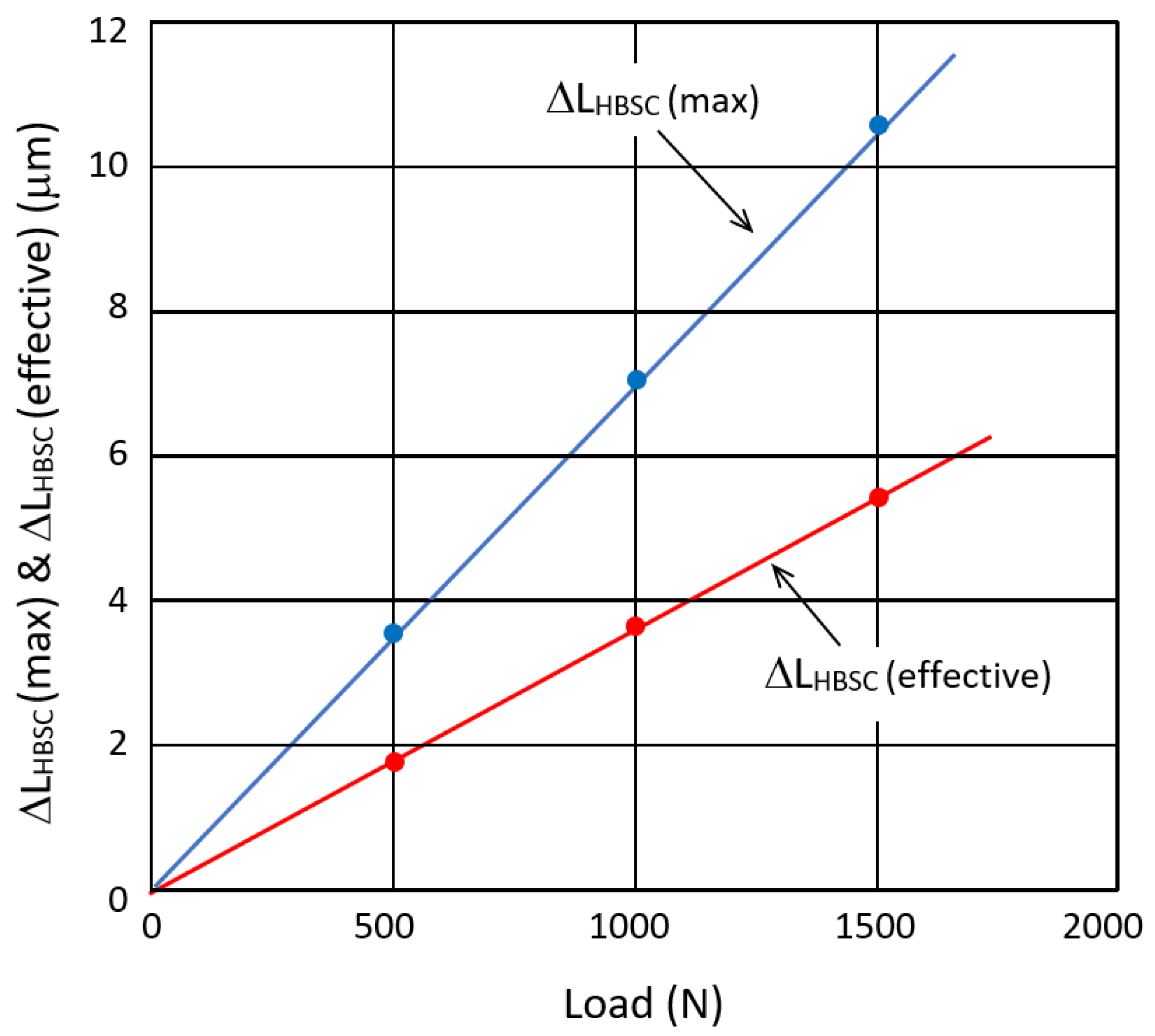
Figure 3b shows the simulation result at 150 kg axial load. It shows that for the half of the HBSC studied, the maximum z-displacement at the top face of the recess base resulting from the bending deformation is about 5.3 µm. This maximum deformation occurs at the central point of the top face of the recess base. Due to symmetry, ΔLHBSC (max) is thus twice this value or 10.6 µm under 150 kg. In reality, the corresponding offset in axial displacement of the HAPA due to the bending effect of the recess base will be determined by the amount of deflection at periphery locations of the 5 × 5 mm2 load bearing area, which is significantly smaller than ΔLHBSC (max). As a conservative estimate, we may take the average z-displacement value in the green zone in Figure 3b as the effective off-set z-displacement, giving a value of about 2.7 µm (Figure 3b) for half of the HBSC. Due to symmetry, the overall contraction of the HAPA actuator due to bending of the recess base, i.e., ΔLHBSC (effective), is thus about 5.4 μm under 150 kg load.
Figure 4 shows the maximum off-set deflection ΔLHBSC (max) at the central point and the effective off-set deflection, ΔLHBSC (effective), due to bending deformation of the recess bases as a function of applied axial load. It shows that ΔLHBSC (effective) ≈ 5.4 µm even under 150 kg axial load, the latter being almost twice the blocking force of individual stacks. The said off-set displacement is <7% of the design stroke (of >80 µm) expected of a 2-level HAPA when commercial PZT stacks of up to 40 mm in length are used.
A check was made to the possibility of local yielding at 150 kg axial load. While two inconspicuous, localized spots with safety factor ≈1 were noted along the periphery of the 5 × 5 mm2 load bearing area at the top face of each recess base, none of such appears at the bottom face. This indicates that the 2.5 mm recess base thickness is sufficient when the axial load is 150 kg. The recess base thickness may be increased accordingly when a larger safety factor is needed.
By applying the same procedure, the deformation of a (2 + 2)-HBCS with circular cross-sectioned recesses was also simulated. It has the same outer dimension of 22 mm, but a slightly longer length of 41 mm. The four recesses have circular cross section of 7.5 mm in bore diameter, 38 mm in depth, and 3 mm in base thickness, and are equally disposed at 12.5 mm P.C.D. The result of z-displacement at the top face of the recess bases at 150 kg is shown in Figure 3c. In this case, the effective off-set displacement, taken again along the periphery area of the 5 × 5 mm2 load bearing area on the top face of the recess base, is represented by a mixture of green-to-yellow colored region and has an average value of about 4.2 μm per half of HBSC. This gives ΔLHBSC (effective) ≈ 8.4 μm for the (2 + 2)-HBSC with said circular cross-sectioned recesses. Safety factor check revealed that no local yielding could be noted at both the top and bottom faces of the recess bases at said axial load.
Our simulation result shows that even at nearly twice the blocking force of individual stacks, the effective off-set displacement of the HBSC remains ≤10% of the overall design stroke of the HAPA actuator, i.e., ΔLHBSC (effective) << 2 × ΔL. The HAPA actuator made from the HBSCs that are described above thus would display nearly twice the stroke of an individual stack and a large blocking force.
4. Experiment Results
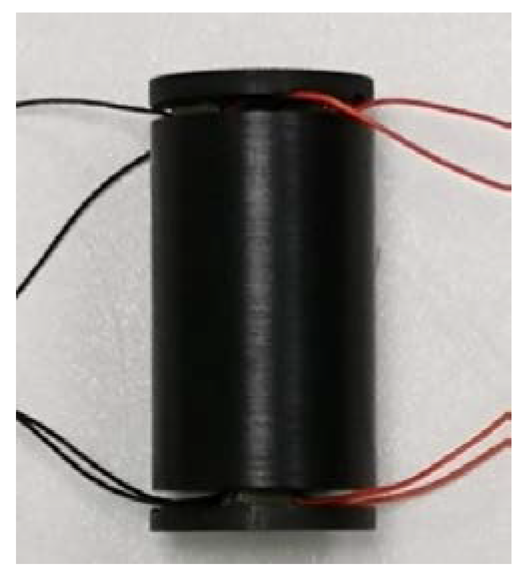
A picture of the HAPA-(2 + 2) actuator fabricated is shown in Figure 5. It has four recesses of 5.5 × 5.5 mm2 in cross-section, each being fitted with one NEC-Tokin stack actuator (Model AE0505D44H40DF; Shiroishi, Japan), of 5 × 5 mm2 in cross-section and 40 mm in length.
The experimental set-up used is the same as that described in [16] but without the polycarbonate heat insulation box. In essence, it consists of a deliberately designed fixture that enables the displacement of the actuator sample to be read off from the digital dial indicator (Mitutoyo 543–561E; Kanagawa, Japan) above and the application of axial compressive loads onto the actuator sample via the addition of weights onto the weight pan below the test bench.
The displacement of a single NEC-Tokin piezoceramic stack actuator (Model AE0505D44H40DF) was first measured under unipolar drive condition. An D.C. power supply was used (Stanford Research PS350/5000V-25W; Sunnyvale, CA, USA). During the measurement, the applied voltage was increased in steps of 20 V each time and the induced displacement was measured by means of the digital dial indicator. The displacement reading was recorded within a few seconds after each voltage step increase. The whole test was completed in less than 10 min.
After which, the axial displacement of a HAPA-(2 + 2) actuator with square cross-sectioned recesses and fitted with four same NEC-Tokin piezoceramic stacks (Figure 5) was measured using the same drive profile and procedure.
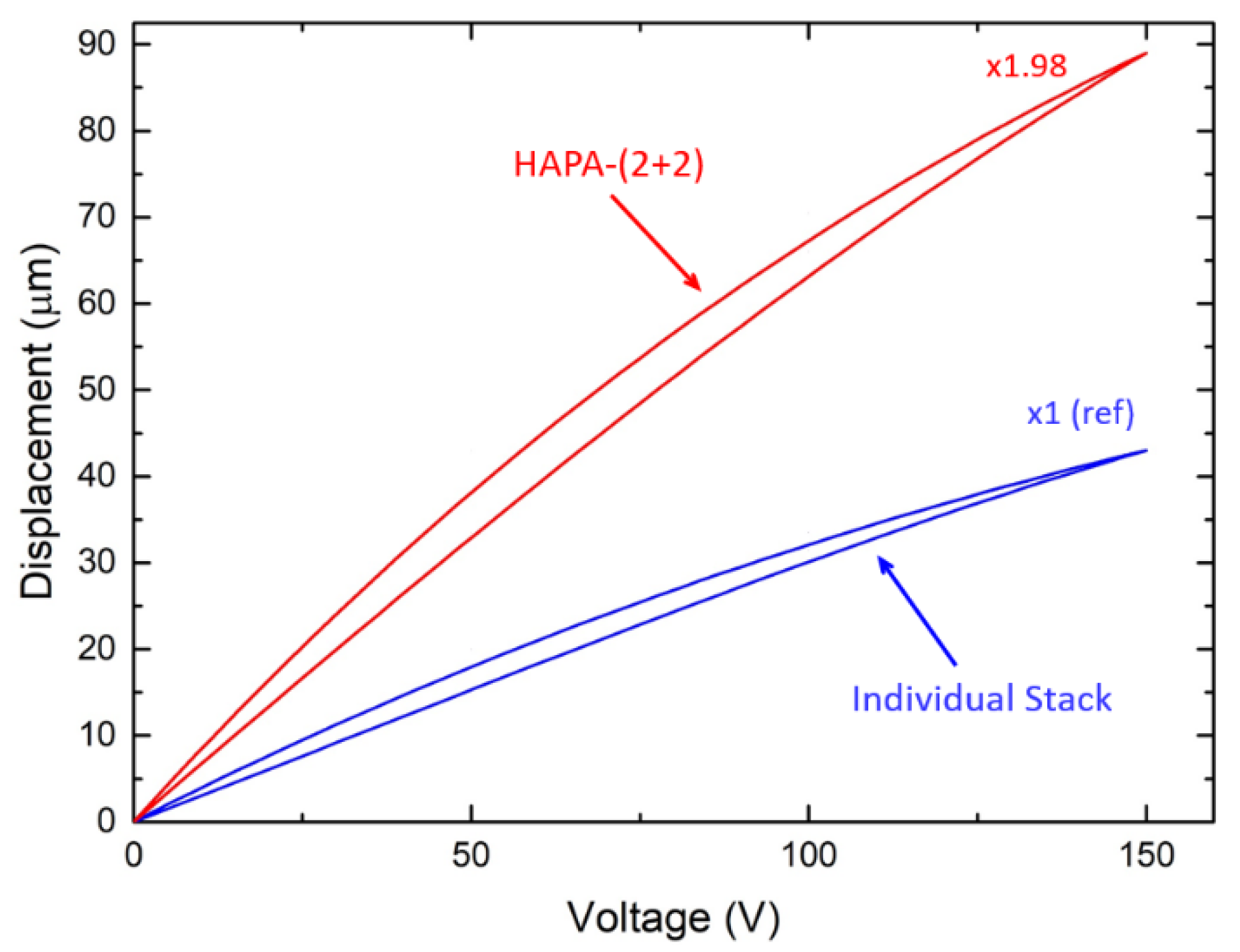
The results of the measurements are shown in Figure 6. It displays two displacement curves, one for the stand-alone piezoceramic stack (in blue) and the other the HAPA-(2 + 2) actuator made of them (in red). It can be seen that, under no added load condition, the HAPA actuator displays an overall axial displacement of 88 μm, as opposed to 44.5 μm for the PZT stack. The experiment results are consistent with the computer simulation result and the design ideology that, when properly designed, the HAPA-(2 + 2) actuator would produce about twice the axial displacement of individual stacks.
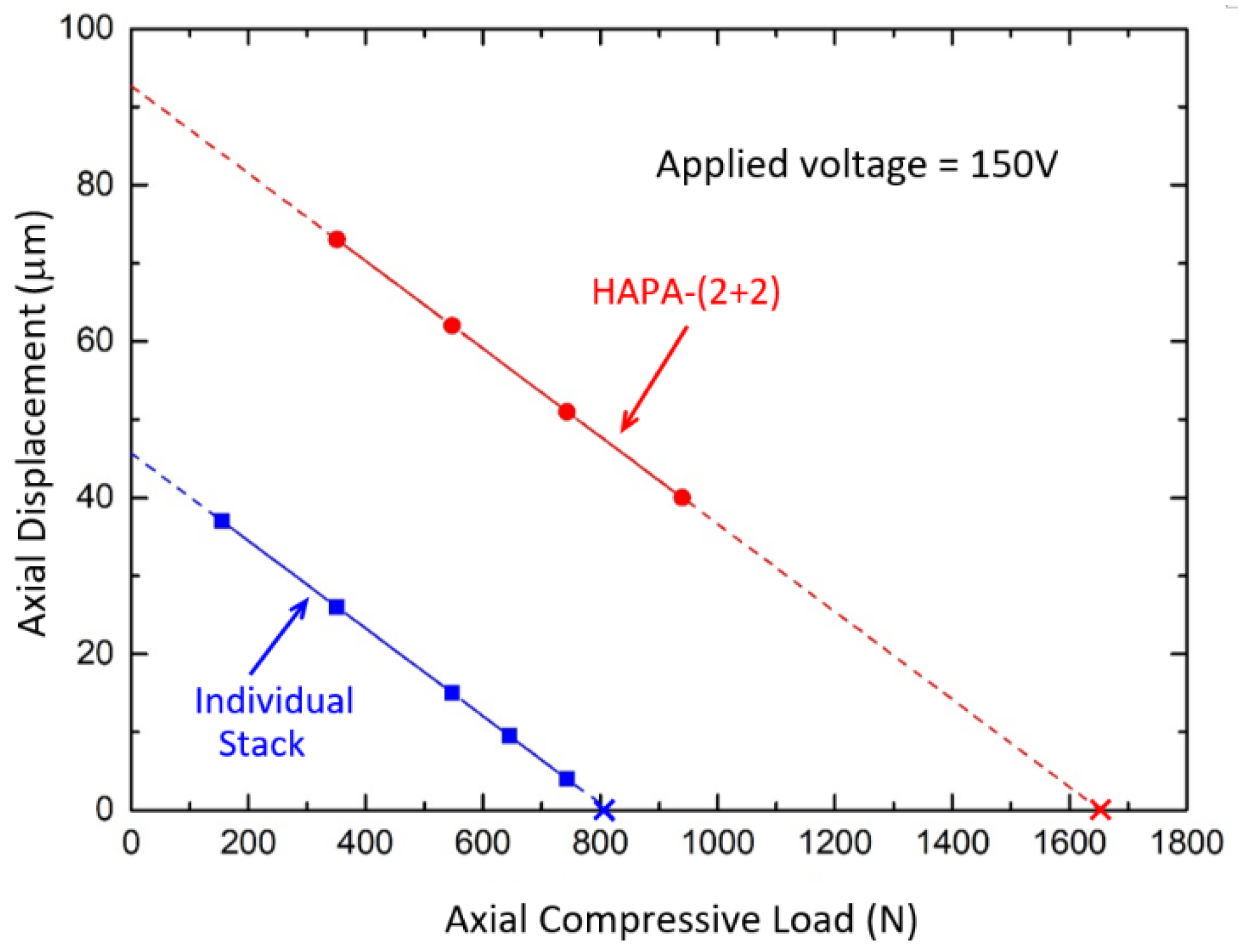
The blocking force diagrams of a NEC-Tokin stack and the HAPA-(2 + 2) actuator sample are shown in Figure 7. In this test, the applied voltage was first increased to 150 V and held there. Increasing load was then applied onto the stack and the HAPA actuator, respectively, by adding dead weights onto the load pan below and the induced contractual displacement was recorded with the aid of the digital dial gage. A special adaptor was designed and fabricated to ensure that the loading was applied evenly onto the cross-section of the stack actuators during the test.
The lower curve of this figure gives a blocking force of about 810 N for the stack actuator. The upper curve is the measurements made on the HAPA sample. Due to weights availability, the maximum load that was applied in this test was 98 kg. Extrapolation of the data gives a blocking force of about 1680 N for the HAPA sample fabricated. The blocking force of the HAPA-(2 + 2) actuator is thus nearly twice that of an individual stack of 800–850 N.
The above results are not surprising considering that the combined load bearing area of the active material in the HAPA-(2 + 2) actuator is twice that of an individual stack. From the simulation results described above, for the HAPA sample, the effective off-set displacement of the HBSC under 150 kg axial load is ≤6 μm, which is ≤7% of the measured stroke of about 88 μm under no added load condition. The HAPA actuator sample thus not only displays about twice the axial displacement but also nearly twice the blocking force of an individual stack. This is possible because four piezoceramic stacks are used in said HAPA actuator and the two-level connector is of high bending stiffness.
Based on the above-described concept, different types of HAPAs, i.e., (1 + 2), (2 + 2), and (3 + 3), have been developed using aluminium-based HBSCs and the same NEC-Tokin piezoceramic stacks as the active elements. The predicted performance of the developed HAPAs are provided in Table 1. For the various HAPAs shown in this table, all the recesses are of circular cross-sections in order to contain the fabrication cost of the HBSC and hence the resultant device.
Table 2 compares the performance of the HAPA-(2 + 2) actuator with other commercially-available displacement amplification mechanisms, including a lever-arm actuator (P.I.-P-601.10; Lederhose, Germany) [17], a flextensional actuator (Cedrat-APA100; Meylan Cedex, France) [18], and a three-cylinder telescopic actuator [14]. It is evident from this table that for actuators of comparable stroke range and size factor, the blocking force of the HAPA-(2 + 2) actuator is many times larger (i.e., >6× to up to 50×). It should be stressed that the HBSCs described in this work are a very simple design and hence cost effective to produce. So are the resultant HAPA actuators when the cost of piezoceramic stack is kept low via quantity order.
Instead of being stand-alone actuators, the various HAPA actuators in Table 1 may be used as the driver of either the lever-arm or flextensional actuator. In so doing, the resultant actuator would display 2× (to 3×) the displacement of its existing counterpart. Although its blocking force may be lowered by a similar ratio, it is still several times larger than the currently available lever-arm, flextensional, and/or telescopic actuators of comparable dimensions.
Our current effort is to fit the HBSCs with “Hi-Fi Stake” piezo single crystal actuators [16,19] to make large stroke (>100 µm) linear actuator of reasonable blocking force (say, >100 N). Tests will also be carried out to evaluate the long-term performance, notably electrical fatigue properties, of the various HAPAs fabricated. The results will be reported elsewhere.
5. Conclusions
In this paper, a high-bending-stiffness connector (HBSC) for housing multiple piezoceramic stacks to form a two-level (2×-) actuation structure is described. Key design requirements for the HBSC are discussed. Computer simulation shows that its effective off-set displacement due to bending deformation of the recess bases remains insignificant even under 150 kg load, the latter being nearly twice the blocking force of individual stack. As a result, the resultant two-level HAPA-(2 + 2) actuator made of such, in which the piezoceramic stacks in respective levels work in unison, displays an overall axial displacement that is about twice that of individual piezoceramic stack despite its length being only fractionally longer. Depending on the design, the HAPA actuators also exhibit high blocking forces, being 1.3× to 3× that of individual stacks. When compared with state-of-the-art amplification mechanisms, like lever-arm, flextensional, and telescopic, the HAPA actuators display many times larger blocking force (say, 7× to 50×) at comparable stroke. In addition to being stand-alone actuators, they can be used as the active material to drive existing displacement amplification schemes to produce piezoelectric actuators of exceptional performance characteristics.
Author Contributions
Conceptualization, L.-C.L. and Y.H.; Methodology, Y.H., D.H.L. and Y.X.X.; Computer Simulation, Y.H. and Y.X.X.; Experimental Investigation, Y.H.; Resources, D.H.L., Y.X.X. and L.-C.L.; Writing-Original Draft Preparation, Y.H.; Editing, L.-C.L.; Project Administration, D.H.L.; Funding Acquisition, nil.
Funding
This research received no external funding.
Acknowledgments
The authors would like to thank Microfine Materials Technologies Pte Ltd., Singapore, for technical support received in the present work including the supply of the HBSC and commercial stack actuators.
Conflicts of Interest
The authors declare no conflict of interest.
References
- Wu, C.C.M.; Lewis, D.; Kahn, M.; Chase, M. High authority, telescopic actuators. Proc. SPIE 1999, 3674, 212–219. [Google Scholar]
- Brei, D.E.; Hallovan, J. Solid State High Authority Telescoping Actuators. Available online: http://www.dtic.mil/dtic/tr/fulltext/u2/ a400693.pdf (accessed on 11 september 2018).
- Niezrecki, C.; Brei, D.; Balahrishnan, S.; Moskalik, A. Piezoelectric actuation: State of the art. Shock Vib. Dig. 2001, 33, 269–280. [Google Scholar] [CrossRef]
- Uchikawa, T. Mechanical Amplification Mechanism Combined with Piezoelectric Elements. U.S. Patent No. US 4,570,095, 11 February 1986. [Google Scholar]
- Asano, H. Piezoelectric Actuator. U.S. Patent No. US 4,783,610A, 8 November 1988. [Google Scholar]
- Xu, W.; King, T.G. Mechanical amplifier design for piezo-actuator applications. In Proceedings of the IEE Manufacturing Division Colloquium on Innovative Actuators for Mechatronic Systems, London, UK, 1–5 January 1995. [Google Scholar]
- Toulis, W.J. Flexural-Extensional Electromechanical Transducer. U.S. Patent No. US 3,277,433, 4 October 1966. [Google Scholar]
- Royster, L.H. The flextensional concept: A new approach to the design of underwater acoustic, transducers. Appl. Acoust. 1970, 3, 117–126. [Google Scholar] [CrossRef]
- Johnson, M.P. Transversely Driven Piston Transducer. U.S. Patent No. US 5,742,561, 21 April 1998. [Google Scholar]
- Joshi, M.; Priya, S. Piezo-bow high displacement and high blocking force actuator. Integr. Ferroelectr. 2005, 82, 25–43. [Google Scholar] [CrossRef]
- Sugawara, Y.; Onitsuka, K.; Yoshikawa, S.; Xu, Q.C.; Newnham, R.E.; Uchino, K. Metal ceramic composite actuators. J. Am. Ceram. Soc. 1992, 75, 996–998. [Google Scholar] [CrossRef]
- Dogan, A.; Uchino, K.; Newnham, R.E. Composite piezoelectric transducer with truncated conical endcaps “cymbal”. IEEE Trans. Ultrason. Ferroelectr. Freq. Control 1997, 44, 597–605. [Google Scholar] [CrossRef]
- Robbins, W.P.; Polla, D.L.; Glumac, D.E. High-displacement piezoelectric actuator utilizing meander-line geometry—Part 1: Experimental characterization. IEEE Trans. Ultrason. Ferroelectr. Freq. Control 1991, 38, 454–460. [Google Scholar] [CrossRef] [PubMed]
- Alexander, P.W.; Brei, D. Piezoceramic telescopic actuator quasi-static experimental characterization. J. Intell. Mater. Syst. Struct. 2003, 14, 643–655. [Google Scholar] [CrossRef]
- Lim, L.C.; Huang, Y.; Xia, Y.X.; Lin, D.H. Displacement Connectors of High Bending Stiffness and Piezoelectric Actuators Made of Such. WIPO/PCT Patent No. WO 2017/176209 A1, 12 October 2017. [Google Scholar]
- Huang, Y.; Zhang, S.; Wang, P.; Xia, Y.X.; Lin, D.H.; Yao, K.; Lim, L.C. Hi-Fi Stake piezo single crystal actuator. Actuators 2018, 7, 60. [Google Scholar] [CrossRef]
- P.I. P-601 PiezoMove Linear Actuator with Guides. Available online: https://www.physikinstrumente.com/en/products/piezoceramic-actuators/linear-actuators/p-601-piezomove-flexure-guided-linear-actuator-202600/ (accessed on 14 August 2018).
- Cedrat Technologies, Amplified Piezoelectric Actuators. Available online: http://www.cedrat-technologies.com/en/products/actuators/apa.html (accessed on 14 August 2018).
- Huang, Y.; Xia, Y.X.; Lin, D.H.; Yao, K.; Lim, L.C. Large stroke high fidelity PZN-PT single-crystal ‘stake’ actuator. IEEE Trans. Ultrason. Ferroelectr. Freq. Control 2017, 64, 1617–1624. [Google Scholar] [CrossRef] [PubMed]
Figure 1.
A (2 + 2)-high-bending-stiffness connector (HBSC): (a) perspective view; (b) a longitudinal cross-section (marked in green); and, (c) mid cross section (marked in yellow) showing the details of the recesses.
Figure 1.
A (2 + 2)-high-bending-stiffness connector (HBSC): (a) perspective view; (b) a longitudinal cross-section (marked in green); and, (c) mid cross section (marked in yellow) showing the details of the recesses.

Figure 2.
Fabrication of high-authority piezoelectric actuator (HAPA) by (a) inserting and bonding 4 piezoelectric stacks (marked blue) at the recess bases of a (2 + 2)-HBSC, and (b) further bonding the top and bottom end caps to complete the construction. The wiring is not shown for clarity sake.
Figure 2.
Fabrication of high-authority piezoelectric actuator (HAPA) by (a) inserting and bonding 4 piezoelectric stacks (marked blue) at the recess bases of a (2 + 2)-HBSC, and (b) further bonding the top and bottom end caps to complete the construction. The wiring is not shown for clarity sake.
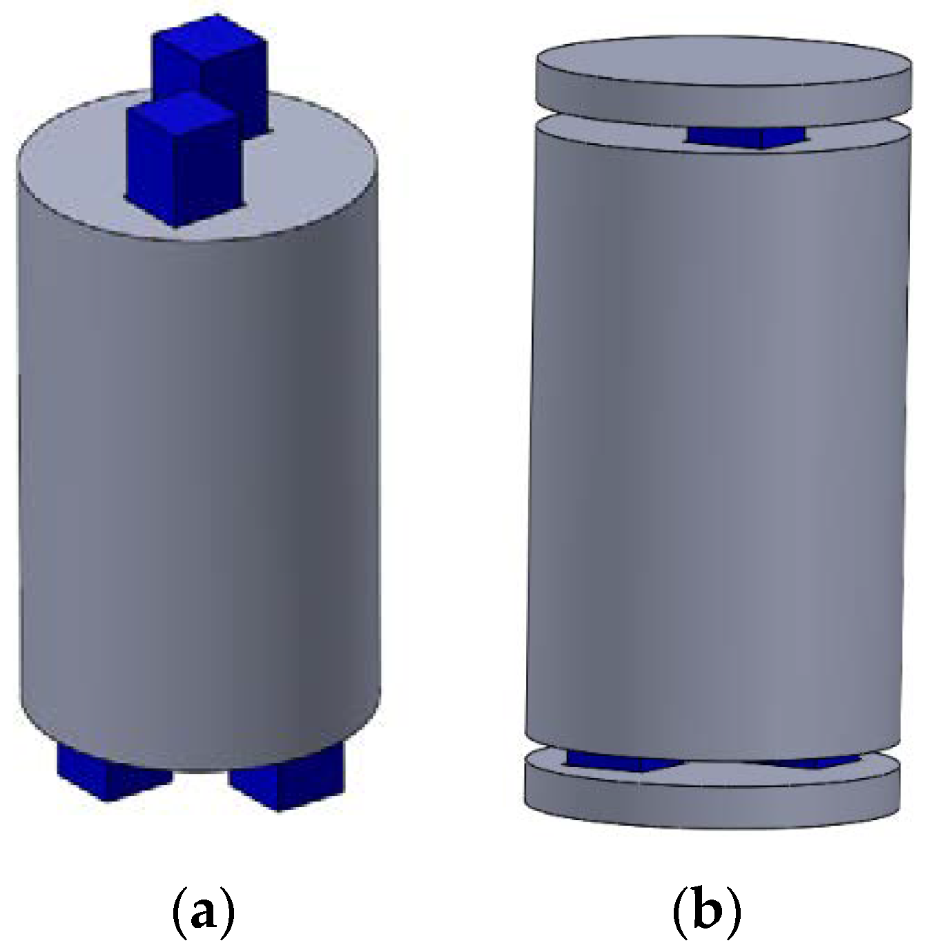
Figure 3.
(a) Top view of a cut (2 + 2)-HBSC showing the reference mid plane (in blue) and the load bearing surfaces (in red) at the base of individual recesses; and, (b) simulation result under 150 kg axial load for (2 + 2)-HBSC with square cross-sectioned recesses of 5.5 × 5.5 mm2 bore dimensions and 2.5 mm base thickness, and (c) for (2 + 2)-HBSC with circular cross-sectioned recesses of 7.5 mm bore diameter and 3 mm base thickness. The color scheme gives the contours of axial (z-) displacement at the top face of respective recess bases.
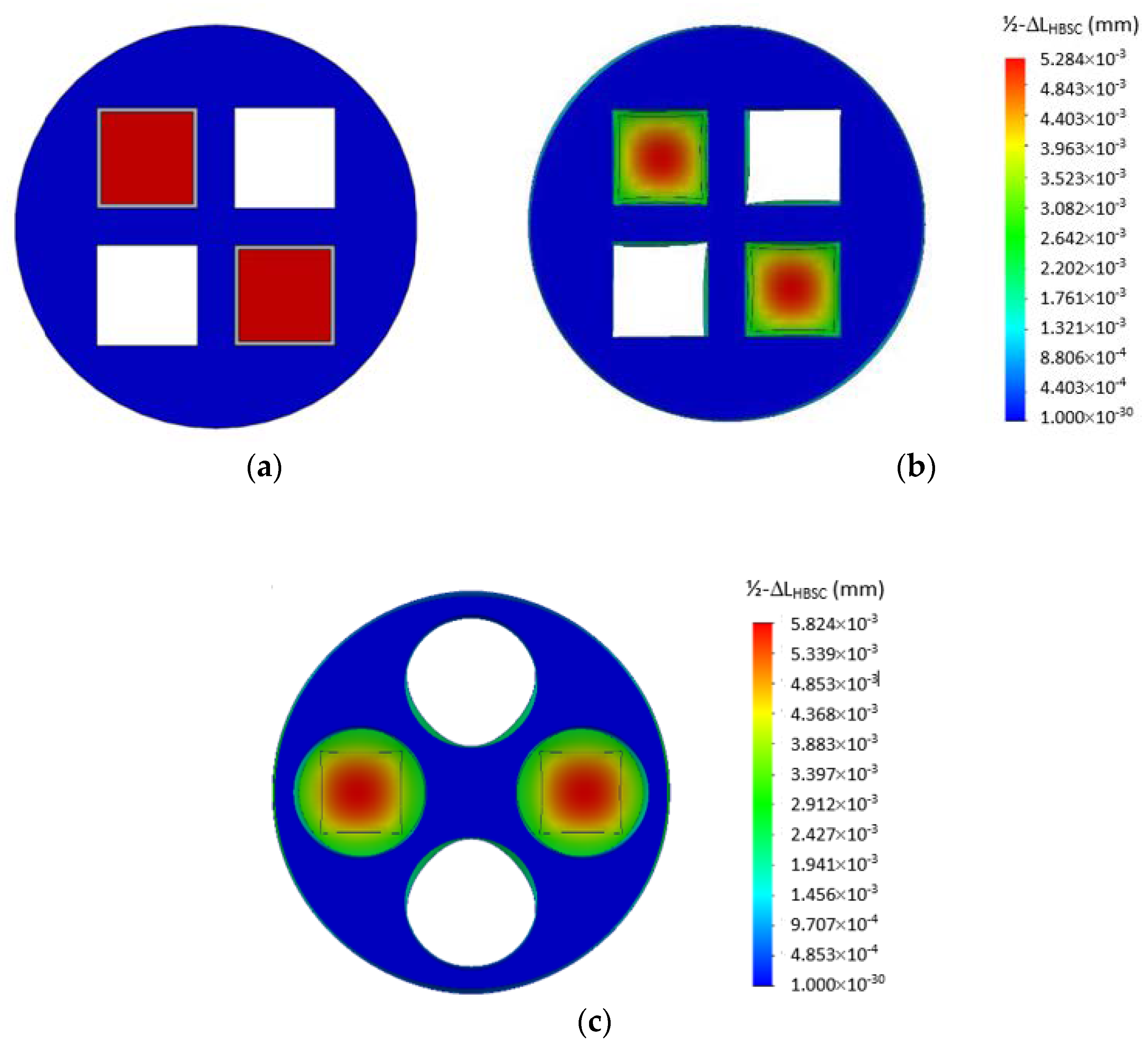
Figure 4.
Maximum off-set deflection ΔLHBSC (max) at the central point and effective off-set deflection ΔLHBSC (effective) around the edge area displayed by the top face of the recess base as a function of applied axial load.
Figure 4.
Maximum off-set deflection ΔLHBSC (max) at the central point and effective off-set deflection ΔLHBSC (effective) around the edge area displayed by the top face of the recess base as a function of applied axial load.

Figure 5.
A picture of the HAPA-(2 + 2) actuator with square-cross-sectioned recesses made from four NEC-Tokin piezoceramic stacks of 5 × 5 mm2 in cross-section and 40 mm in length.
Figure 5.
A picture of the HAPA-(2 + 2) actuator with square-cross-sectioned recesses made from four NEC-Tokin piezoceramic stacks of 5 × 5 mm2 in cross-section and 40 mm in length.

Figure 6.
Unipolar displacement responses for both NEC-Tokin piezoceramic stack (Model AE0505D44H40DF) and the HAPA-(2 + 2) actuator fabricated from the same under no added load condition. The maximum applied voltage used was 150 V.
Figure 6.
Unipolar displacement responses for both NEC-Tokin piezoceramic stack (Model AE0505D44H40DF) and the HAPA-(2 + 2) actuator fabricated from the same under no added load condition. The maximum applied voltage used was 150 V.

Figure 7.
Displacement versus axial compressive load for an NEC-Tokin piezoceramic stack (Model AE0505D44H40DF) and the fabricated HAPA-(2 + 2) actuator, both being driven at 150 V. The crosses on the abscissa mark the blocking forces of respective actuators at said applied voltage.
Figure 7.
Displacement versus axial compressive load for an NEC-Tokin piezoceramic stack (Model AE0505D44H40DF) and the fabricated HAPA-(2 + 2) actuator, both being driven at 150 V. The crosses on the abscissa mark the blocking forces of respective actuators at said applied voltage.


Table 1.
Performance of various HAPAs made from NEC-Tokin piezoceramic stacks of 5 × 5 mm2 in cross-section and 40 mm in length.
Table 1.
Performance of various HAPAs made from NEC-Tokin piezoceramic stacks of 5 × 5 mm2 in cross-section and 40 mm in length.
| Type of HAPA | External Dimensions (mm3) | Stroke @ 150 V (µm) | Blocking Force (N) | Stiffness (N/µm) | Operating Temperature Range (°C) | |
|---|---|---|---|---|---|---|
 | HAPA-(1 + 2) | 29 × 12 × 47 (L) | 85 | 1100 | 13 | −25 to + 80 |
 | HAPA-(2 + 2) | φ 24 × 47 (L) | 1700 | 20 | ||
 | HAPA-(3 + 3) | φ 32 × 47 (L) | 2500 | 30 | ||
Table 2.
Performance comparison of HAPA, lever-arm, flextensional, and telescopic actuators.
| Product/Model | Size (mm3) | Stroke (μm) | Blocking Force (N) |
|---|---|---|---|
| HAPA-(2 + 2) (Present work) | φ24 × 47 (H) * | 88 | 1700 |
| P.I.-P-601.10 [15] (Lever-arm) | 46.5 (L) × 12 (D) × 16.5 (H) * | 100 | 30 |
| Cedrat-APA100 [16] (Flextensional) | 55.2 (L) × 10.5 (D) × 25.2 (H) * | 126 | 235 |
| Telescopic [14] (3-cylinder design) | φ26.5 × 80 (H) * (approx.) | 22–28 † | 257–270 † |
* The height (H) is also the active direction of respective devices. † Measured at 300 V; one sample gave 33 µm stroke and 370 N blocking force when measured at 400 V.
© 2018 by the authors. Licensee MDPI, Basel, Switzerland. This article is an open access article distributed under the terms and conditions of the Creative Commons Attribution (CC BY) license (http://creativecommons.org/licenses/by/4.0/).
Share and Cite
MDPI and ACS Style
Huang, Y.; Xia, Y.X.; Lin, D.H.; Lim, L.-C. High-Bending-Stiffness Connector (HBSC) and High-Authority Piezoelectric Actuator (HAPA) Made of Such. Actuators 2018, 7, 61. https://doi.org/10.3390/act7030061
AMA Style
Huang Y, Xia YX, Lin DH, Lim L-C. High-Bending-Stiffness Connector (HBSC) and High-Authority Piezoelectric Actuator (HAPA) Made of Such. Actuators. 2018; 7(3):61. https://doi.org/10.3390/act7030061
Chicago/Turabian StyleHuang, Yu, Yue Xue Xia, Dian Hua Lin, and Leong-Chew Lim. 2018. "High-Bending-Stiffness Connector (HBSC) and High-Authority Piezoelectric Actuator (HAPA) Made of Such" Actuators 7, no. 3: 61. https://doi.org/10.3390/act7030061
Note that from the first issue of 2016, this journal uses article numbers instead of page numbers. See further details here.