Abstract
Recently, lightweight and flexible soft actuators have attracted interest from robotics researchers. We focused on pneumatic rubber artificial muscle (PAM) as a high-output soft actuator. The high compliance of PAM allows a robot to adapt flexibly to the environment without many external sensors. Although PAM has these characteristics, it is difficult to control because of the nonlinearity between the input and output and the delay of air response. This limits the accuracy of artificial muscles and complicates motion planning. Therefore, we considered that PAM can be driven by simplified control laws, so that the entire system shows emergent motion guided by metaheuristics. We developed a legged robot with two joints driven by PAMs. Each PAM was controlled with a cyclic signal, and the genetic algorithm was applied to optimize these signals. We tested to check whether the behavior of the PAMs is changed by the genetic algorithm using three simple performance indexes. We found out that although the genetic algorithm adjusted the local cyclic inputs appropriately according to each performance index, the time-varying characteristic of PAMs disturbed the monotonic increment of the evaluation values. We also discovered that by only adjusting the input timing, the leg develops a limitation in robustness.
1. Introduction
Recently, soft actuators have attracted interest from robotics researchers for their characteristics of flexibility and light weight. Due to their flexibility, soft actuators can allow high backdrivability in case of collision with humans, thus preventing injury. Therefore, they are regarded as human-friendly actuators. Soft actuators come in a variety of types with various drive mechanisms, materials, and output powers.
This study focuses on pneumatic rubber artificial muscle (PAM) for use as a high-output soft actuator [1,2]. PAM is typically made of rubber tubing and fiber sheaths, and is deformed with air pressure. It can generate hundreds or thousands of Newtons of output force at a contraction ratio of about 40%. In addition, its output characteristics are similar to those of a human muscle. Due to this similarity, PAMs are used often for human-friendly robots or wearable devices such as cooperative working robots, power-assist devices [3], nursing-care robots, and rehabilitation systems [4].
The high compliance of PAMs also makes it possible to build a robot that can adapt constructively to an environment using relatively few external sensors. In a complex environment such as irregular terrain and with many objects, a robot driven by soft actuators can flexibly change its own position and motion. For example, a manipulator can approach and grab a target object with rough position control, and a legged robot can adapt its legs to unpredictable terrain.
Although PAMs have these characteristics, they are difficult to control precisely because of nonlinearity between the input and output, the delay of the pneumatic response, and hysteresis. To linearize characteristics, Nakamura approached feedforward control with a mechanical equilibrium model of the PAM [5]. Furthermore, to apply the position and force feedback control and an internal model of the air pressure response [6], PAM has been controlled theoretically without divergent behavior. Ahn presented a control method using robust time-delay nonlinear (RTN) technique [7]. Compensation of hysteresis based on modeling is also attracting attention [8,9,10]. Generally, these studies intend to control PAM in a more stable and accurate manner.
On the other hand, we hypothesized that PAMs can be driven by simpler control laws so that the whole system shows emergence of motion by metaheuristics. Since metaheuristics does not depend on the problem, we expect it to be applied widely to control systems that use PAMs. In our design, each PAM is driven by a simple law of individuals that has no information about the target task. By adjusting the parameters of these laws according to evaluations of the motion, the robot can achieve the task. Although there are some research studies using PAMs and metaheuristics, their purpose is to construct nonlinear models such as PAM by using algorithms [11,12]. This architecture is inspired by the autonomous decentralized control system proposed by Ishiguro, which controls a cyclic walking robot with motors [13]. In this paper, we describe the development of a control system for a robot leg with two joints driven by PAMs. Each PAM is controlled with a cyclic signal. We applied the genetic algorithm, which is a kind of metaheuristic, in order to optimize the signals. We suppose that this approach can optimize the motion of a robot having nonlinearity response, and can also reduce the delay of PAMs by evaluating consequent motion including these drawbacks. Our goal is optimizing leg motion with the environment, task, and condition of the robot. This paper reports initial tests to verify that the PAM behavior changes according to simple evaluation functions by the genetic algorithm.
2. Straight-Fiber-Type Artificial Muscle
Figure 1 shows photographs of the straight-fiber artificial muscle (SFPAM), which is a specific PAM. It is made from carbon fibers and a latex rubber tube. These carbon fibers run only along the longitudinal direction of the latex rubber tube, which limits the axial length of the tube walls. With this structure, the SFPAM expands in the radial direction and contracts in the longitudinal direction when air pressure is applied. Due to the freedom to expand in the radial direction and the fixed axial length of the fiber sheath, SFPAM can translate radial expansion to axial contraction effectively. Thus, SFPAM has a higher contraction percentage and output than those of the McKibben-type PAM, which is also popular. Figure 2 shows a schematic of the SFPAM tested in this study. The initial length l0 is 210 mm, inner diameter d is 11 mm, outer diameter D is 15 mm, and weight is 0.058 kg.
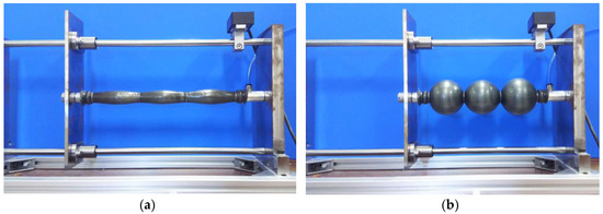
Figure 1.
The straight-fiber artificial muscle ((a) air released, (b) air applied).
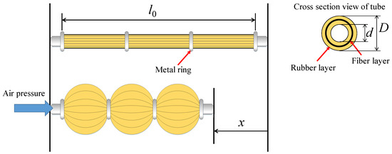
Figure 2.
The schematic of the straight-fiber artificial muscle (SFPAM).
3. Single-Leg Robot with PAM
Figure 3 and Figure 4 show the two-DOF (degree of freedom) leg robot with PAMs that we have developed, and Table 1 lists its specifications. In each joint, two artificial muscles are arranged in parallel and linked with a belt pulley. The belt pulley transmits contractile force from the artificial muscles to the rotation of the joint. By this mechanism, alternate contraction of the PAMs rotates the joint, and the contraction of both PAMs increases joint stiffness. In what follows, we distinguish PAMs with indexes similar to PAMij (i is the number of the joint, and j indicates whether the actuator is the extensor or flexor).
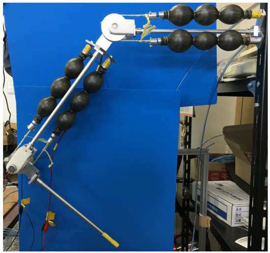
Figure 3.
The two-DOF robot leg with pneumatic rubber artificial muscles (PAMs).
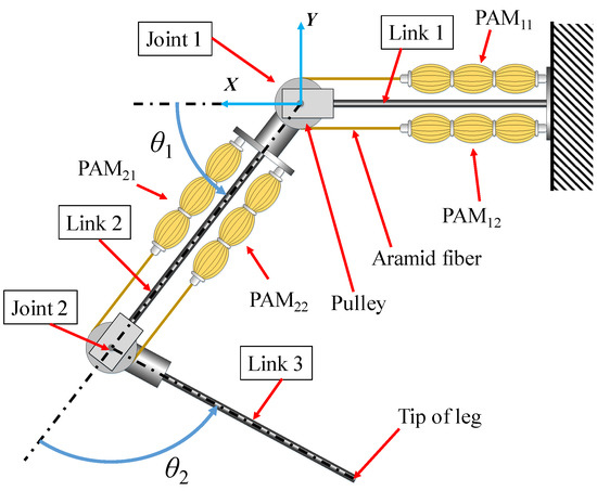
Figure 4.
Schematic of the tested two-DOF robot leg with PAMs.

Table 1.
Specifications of the robot.
The control system of this robot is as shown in Figure 5. We used a digital signal processor (sBOXII, MTT Corp., Tokyo, Japan) to control the robot. Air pressure is applied to each PAM through a solenoid valve (GFAG21-Z-8-12C-3, CKD Corp., Aichi, Japan). This valve has two input (upstream side) ports and one output (PAM side) port. Each input port is connected to an electropneumatic regulator (ITV1050-211L, SMC Corp., Tokyo, Japan). In this study, the two regulators are fixed at low pressure and high pressure. By switching the input ports of the solenoid valve, high or low air pressure is applied to the PAM. The angle of each joint is monitored with a rotary potentiometer. In addition, the motion of the leg is calculated from these sensor values using forward kinematics.
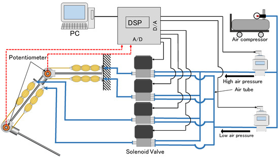
Figure 5.
The control system of the robot.
4. Controller Using Cyclic Input and Genetic Algorithm
In this section, we explain the controller for the leg robot. Natural creatures can walk at an unconscious level. Although humans do not think about motion of each muscle, we can walk on uneven terrain easily. This is accomplished by spinal reflex, and muscles receive only simple nerve pulses. Therefore, we considered that a robot could be controlled by a distributed system of semi-autonomous controllers. Generically, a cyclic motion such as walking is easier to achieve than aperiodic motion. Thus, we chose to attempt cyclic motion as the first step in this research. This section first discusses the local cyclic input controllers for each PAM, and then discusses the global genetic algorithm controller.
4.1. Cyclic Input Controller for PAM
When humans or animals walk, muscles receive oscillating signals from neurons and cyclic motion such as walking is generated because of the collaboration between muscles. Thus, we utilized a rectangular wave generator as the local controller for PAM. This wave signal is sent to the solenoid valve through the amplifier, and switches the input to either high or low pressure. To obtain a versatile solution for generating a cyclic motion with the PAM system, this controller has only two variable parameters and two static parameters, and makes no direct attempt at leg motion. The two variable parameters are the frequency and phase of the rectangular wave, whereas the two static parameters are the pressure of each input port of solenoid valve.
The following equations describe the pressure generated by this local controller. In these equations, Pij is the output pressure from PAMij, Ph is the high input port pressure, Pl is the low input port pressure, ωij is the frequency of the rectangular wave, and φij is the phase shift of the wave. When both PAMs in a joint are driven at high pressure, the angle of the joint is same as when both PAMs are driven at low pressure. However, the joint stiffness is much higher with both actuators at high pressure. To avoid the breakdown of the robot, both PAMs apply low pressure for this neutral joint angle. Here, Figure 6 and Figure 7 are shown to explain the joint motion. Figure 6 shows a joint unit driven by PAM1 and PAM2. Figure 7 shows an example of the signal wave for each PAM and motion of the joint (the high-pressure value is 0.105 MPa, and the low pressure is 0.065 MPa in this example). By this controller, intricate joint motion can be generated as a result of the interworking of PAMs.
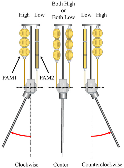
Figure 6.
Relationship between PAM pressure and joint motion.
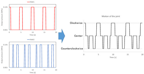
Figure 7.
Examples of rectangular wave signals (ω1 = 0.4 Hz, φ1 = π/2, ω2 = 0.2 Hz, φ2 = 23π/16) (left) and motion of the joint (right).
4.2. Genetic Algorithm
The local controllers discussed in the previous section each have two variable parameters: frequency and phase shift of cyclic input. Thus, one leg has eight parameters (two parameters by four PAMs). Global regularity is required to control the local motions. This control system is aiming to adjust these parameters automatically with trial and error in the field. We suppose that by evaluating the consequent motion including non-linearity response and delay of PAMs, the controller can optimize the motion of the robot by considering these drawbacks. Therefore, we choose a genetic algorithm for the main logic of the global controller. A genetic algorithm is a metaheuristic algorithm inspired by the selection, crossover, and mutation of genes. At first, individuals with a random gene are selected. Then, the selected individuals make new individuals in the next generation by gene crossover. By iterating this process, the gene will be optimized. In addition, mutation occurs to avoid local solutions during the process.
The detailed procedure used in this study is as follows.
- Initialize eight parameters of N genes at random in a fixed range (N is population number).
- Drive the robot using each gene.
- Evaluate the result of each motion with an evaluation function.
- Select the best gene as “gene A”.
- Select the next gene as “gene B” using roulette wheel selection.
- Cross gene A with gene B (crossover rate is 50% and mutation rate is 10%).
- These genes and gene A (elite gene) are set as the next generation, and this procedure is repeated from step 2.
In this study, the coding type of genetic algorithm is real-number coding, whereas the evaluation function is used for the selection of fitted genes (synonymy of cost function and fitness function). Furthermore, we applied the elite selection method and roulette wheel selection method in the selection of genes.
5. Experiment
In this section, experiments with the actual equipment are discussed. Through this experiment, we confirmed that local cyclic input controllers and a genetic algorithm can control a system constructed with PAMs. We also conduct the same experiment, but with applying load. We expect that the proposed control system adjusts the inputs of the PAMs to accommodate different load conditions. Since it is hard to evaluate the walking function with only a single leg, we set simple targets (larger trajectory, horizontal swing, and vertical swing) for evaluation functions. This preliminary experiment aims to demonstrate that the controller can work for a system with PAMs. Therefore, we formulated some simple evaluation functions so that we could easily compare the results of the evaluation functions.
5.1. Evaluation Functions
To control the leg robot with PAMs, three evaluation functions were formulated and are shown as Equations (4)–(6). These equations are expected to work as follows.
- Evaluation function 1 (Equation (4)) makes the trajectory of the leg tip expand horizontally and vertically (larger trajectory).
- Evaluation function 2 (Equation (5)) makes the trajectory of the leg tip expand horizontally and shrink vertically (horizontal swing).
- Evaluation function 3 (Equation (6)) makes the trajectory of the leg tip shrink horizontally and expand vertically (vertical swing).where X and Y are the widths of the trajectory in the horizontal and vertical directions, respectively, and Xmax and Ymax are the mechanistic maximum widths of the trajectory. Then, from C1 to C6 are weight coefficients. In this study, all of the weight coefficients are set at 0.5.
5.2. Demonstration of Driving the Leg Robot without Load
This subsection discusses the demonstration of driving the leg robot. The PAMs of the robot are supplied with air pressure according to the local cyclic input controllers. The parameters of cyclic input are adjusted by the genetic algorithm metaheuristic. The genetic algorithm uses evaluation functions to evaluate and adjust the motion of the leg. Table 2 lists the experimental conditions. The robot leg is driven for 15 s while testing each gene to complete enough cycles of the motion.
Table 2.
Experimental conditions.
The results of the experiments are shown in Figure 8, Figure 9, Figure 10, Figure 11, Figure 12 and Figure 13, and Figure 14 shows the evaluation value of each experiment. From Figure 8, Figure 10, Figure 12 and Figure 14, notice that although the leg tip trajectories changed according to the evaluation function, the evaluation value did not increase monotonically. By applying the elite selection method to select genes, we expected the evaluation values to not decrease. However, because of time-varying characteristic of PAMs, the leg robot could not exert the same performance as previous generations with the same parameter. Evaluations 2 and 3 alter the trajectory more closely to the expected result. Evaluation function 2 was expected to generate horizontal swing, and evaluation function 3 was expected to generate vertical swing. In particular, evaluation function 2 showed a trajectory that was noticeably close to a horizontal line. We suppose that these trajectories were affected by the structure of the leg and the range of each joint. Figure 15 shows the manipulability ellipsoid of the robot leg when the tip is at [0, −600]. From this ellipsoid, this tip of the leg draws horizontal trajectories more easily than vertical trajectories. Therefore, designing an arbitrary trajectory directly with an explicit evaluation function would not be sufficient. We expect that emergent motion plans for specific tasks will be made possible by formulating an evaluation function that relates to the comprehensive behavior of a robot.
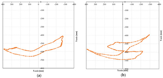
Figure 8.
Trajectory of leg tip using evaluation function 1 without load ((a) first generation, (b) 18th generation).
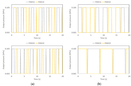
Figure 9.
Cyclic inputs to PAMs using evaluation function 1 without load ((a) first generation, (b) 18th generation).
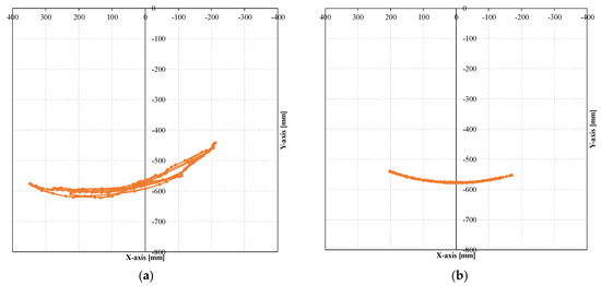
Figure 10.
Trajectory of the leg tip using evaluation function 2 without load ((a) first generation, (b) 18th generation).
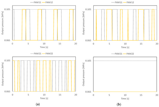
Figure 11.
Cyclic inputs to PAMs using evaluation function 2 without load ((a) first generation, (b) 18th generation).
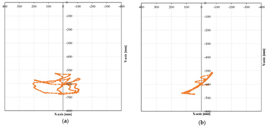
Figure 12.
Trajectory of the leg tip using evaluation function 3 without load ((a) first generation, (b) 18th generation).
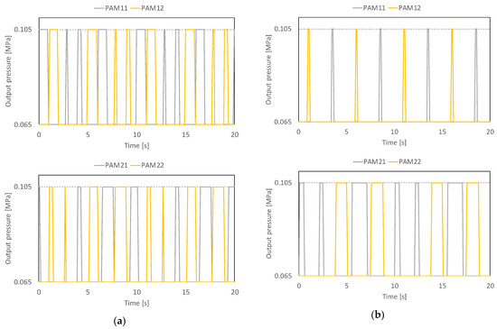
Figure 13.
Cyclic inputs of PAMs using evaluation function 2 without load ((a) first generation, (b) 18th generation).
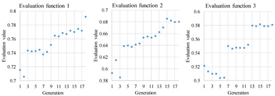
Figure 14.
Evaluation value of each experiment (without load).
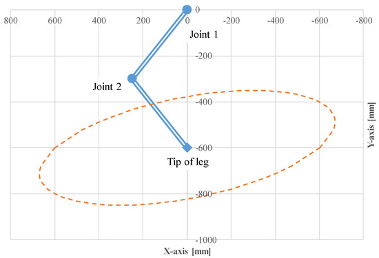
Figure 15.
Manipulability ellipsoid of the leg around [0, −600].
5.3. Demonstration of Driving the Leg Robot with Load
In this subsection, we added a load (0.5 kg) at the tip of leg, and conducted the same experiments as Section 5.2. Figure 16, Figure 17, Figure 18, Figure 19, Figure 20 and Figure 21 show the experimental results, and Figure 22 shows the evaluation values of each experiment. From Figure 16, Figure 18 and Figure 21, the evaluation of the trajectory using evaluation functions 1 and 2 became lower than the results without a load. Although the result of evaluation function 3 obtained a higher evaluation value than the result without a load, it was because that initial parameters were well. In fact, an increment amount of the evaluation value with evaluation function 3 was small. We presume that the leg was affected by the load because of low joint stiffness. This controller fixed maximum and minimum pressure, and thus, the leg has a limitation in robustness with only adjusting input timing.
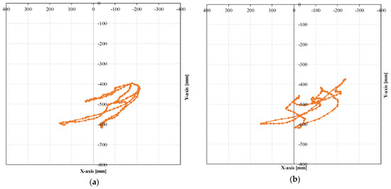
Figure 16.
Trajectory of the leg tip using evaluation function 1 with 0.5 kg ((a) first generation, (b) 18th generation).
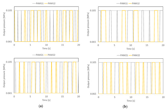
Figure 17.
Cyclic inputs of PAMs using evaluation function 1 with 0.5 kg ((a) first generation, (b) 18th generation).
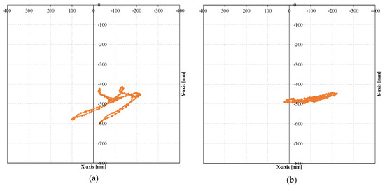
Figure 18.
Trajectory of the leg tip using evaluation function 2 with 0.5 kg ((a) first generation, (b) 18th generation).
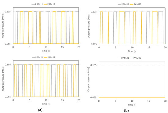
Figure 19.
Cyclic inputs of PAMs using evaluation function 2 with 0.5 kg ((a) first generation, (b) 18th generation).
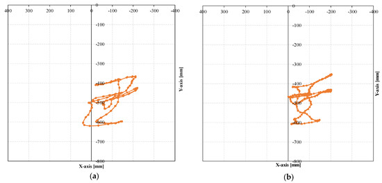
Figure 20.
Trajectory of the leg tip using evaluation function 3 with 0.5 kg ((a) first generation, (b) 18th generation).
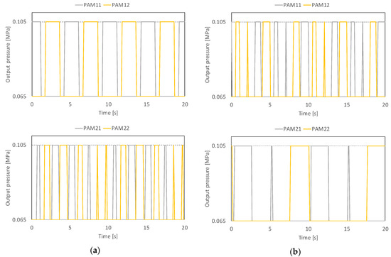
Figure 21.
Cyclic inputs of PAMs using evaluation function 3 with 0.5 kg ((a) first generation, (b) 18th generation).
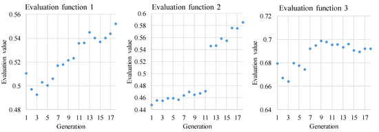
Figure 22.
Evaluation value of each experiment (with 0.5 kg).
6. Conclusions
This research presented a control method for a simple PAM-driven robot that can adjust behavior according to evaluation functions. Emergency motion planning was the focus because re-planning can encourage adaptability in indeterminate environments such as irregular terrain. In this paper, cyclic input controllers and genetic algorithm metaheuristics were applied to control a two-jointed leg. The leg was driven by the proposed method using three evaluation functions. The genetic algorithm global heuristic adjusted the local cyclic inputs according to each evaluation function. However, evaluation values did not increase monotonically because of the time-varying characteristic of PAMs. We also supposed that these trajectories tend to be affected by the manipulability ellipsoid of the robot leg. Then, we added a load (0.5 kg) at the tip of leg and conducted the same experiments. From these results, we presumed that the leg was affected by load because of low joint stiffness. Thus, we found out that the leg has a limitation in robustness with only adjusting input timing. Through this study, we conclude that a new global controller needs to be constructed instead of the genetic algorithm.
In future works, we plan to construct a global controller based on an autonomous decentralized control system that can control the robot in real time. Furthermore, we plan to develop a four-legged robot to conduct a walking experiment.
Author Contributions
Conceptualization, H.T.; Investigation, K.H.; Project administration, H.T.; Software, K.H.; Supervision, H.T.; Validation, K.H.; Writing—original draft, H.T.
Acknowledgments
This research is partially supported by the Program on Open Innovation Platform with Enterprises, Research Institute and Academia (OPERA) from Japan Science and Technology Agency (JST). The joints of the robot leg use aramid fiber provided by TEIJIN LIMITED, for which we would like to express gratitude.
Conflicts of Interest
The authors declare no conflict of interest.
References
- Tomori, H.; Nakamura, T. Theoretical comparison of McKibben-type artificial muscle and novel straight-fiber-type artificial muscle. Int. J. Autom. Technol. 2011, 5, 544–550. [Google Scholar] [CrossRef]
- Nakamura, T. Experimental comparisons between McKibben type artificial muscles and straight fibers type artificial muscles. Proc. SPIE 2007, 6414, 641424. [Google Scholar] [CrossRef]
- Sasaki, D.; Noritsugu, T.; Takaiwa, M. Development of high contractile pneumatic artificial rubber muscle for power assist device. In The Abstracts of the International Conference on Advanced Mechatronics: Toward Evolutionary Fusion of IT and Mechatronics: ICAM; The Japan Society of Mechanical Engineers: Tokyo, Japan, 2010; Volume 5, pp. 774–779. [Google Scholar]
- More, M.; Liska, O.; Kovac, J. Experimental verification of force feedback for rehabilitation robot. Int. J. Eng. Res. Afr. 2015, 18, 123–129. [Google Scholar] [CrossRef]
- Nakamura, T.; Shinohara, H. Position and force control based on mathematical models of pneumatic artificial muscles reinforced by straight glass fibers. In Proceedings of the IEEE International Conference on Robotics and Automation (ICRA 2007), Roma, Italy, 10–14 April 2007; pp. 4361–4366. [Google Scholar]
- Nakamura, T.; Midorikawa, Y.; Tomori, H. Position and vibration control of variable rheological joints using artificial muscles and magneto-rheological brake. Int. J. Humanoid Robot. 2011, 8, 205–222. [Google Scholar] [CrossRef]
- Ba, D.X.; Ahn, K.K. A robust time-delay nonlinear controller for a pneumatic artificial muscle. Int. J. Precis. Eng. Manuf. 2018, 19, 23–30. [Google Scholar] [CrossRef]
- Aschemann, H.; Schindele, D. Comparison of model-based approaches to the compensation of hysteresis in the force characteristic of pneumatic muscles. IEEE Trans. Ind. Electron. 2014, 61, 3620–3629. [Google Scholar] [CrossRef]
- Lin, C.J.; Lin, C.R.; Yu, S.K.; Chen, C.T. Hysteresis modeling and tracking control for a dual pneumatic artificial muscle system using Prandtl–Ishlinskii model. Mechatronics 2015, 28, 35–45. [Google Scholar] [CrossRef]
- Xiea, S.L.; Liua, H.T.; Meia, J.P.; Gub, G.Y. Modeling and compensation of asymmetric hysteresis for pneumatic artificial muscles with a modified generalized Prandtl–Ishlinskii model. Mechatronics 2018, 52, 49–57. [Google Scholar] [CrossRef]
- Song, C.; Xie, S.Q.; Zhou, Z.; Hu, Y. Modeling of pneumatic artificial muscle using a hybrid artificial neural network approach. Mechatronics 2015, 31, 124–131. [Google Scholar] [CrossRef]
- Anh, H.P.H.; Ahn, K.K. Identification of pneumatic artificial muscle manipulators by a MGA-based nonlinear NARX fuzzy model. Mechatronics 2009, 19, 106–133. [Google Scholar] [CrossRef]
- Owaki, D.; Kano, T.; Nagasawa, K.; Tero, A.; Ishiguro, A. Simple robot suggests physical interlimb communication is essential for quadruped walking. J. R. Soc. Interface 2013, 10. [Google Scholar] [CrossRef] [PubMed]
© 2018 by the authors. Licensee MDPI, Basel, Switzerland. This article is an open access article distributed under the terms and conditions of the Creative Commons Attribution (CC BY) license (http://creativecommons.org/licenses/by/4.0/).