
Performance and Applications of L1B2 Ultrasonic Motors

Nanomotion Ltd., 3 Hayetsira St., Yokneam 20692, Israel
*
Author to whom correspondence should be addressed.
Actuators 2016, 5(2), 15; https://doi.org/10.3390/act5020015
Submission received: 13 April 2016
/
Revised: 19 May 2016
/
Accepted: 25 May 2016
/
Published: 1 June 2016
(This article belongs to the Special Issue Piezoelectric Actuators)
Abstract
:Piezoelectric ultrasonic motors offer important advantages for motion applications where high speed is coupled with high precision. The advances made in the recent decades in the field of ultrasonic motor based motion solutions allow the construction of complete motion platforms in the fields of semiconductors, aerospace and electro-optics. Among the various motor designs, the L1B2 motor type has been successful in industrial applications, offering high precision, effective control and operational robustness. This paper reviews the design of high precision motion solutions based on L1B2 ultrasonic motors—from the basic motor structure to the complete motion solution architecture, including motor drive and control, material considerations and performance envelope. The performance is demonstrated, via constructed motion stages, to exhibit fast move and settle, a repeatability window of tens of nanometers, lifetime into the tens of millions of operational cycles, and compatibility with clean room and aerospace environments. Example stages and modules for semiconductor, aerospace, electro-optical and biomedical applications are presented. The described semiconductor and aerospace solutions are powered by Nanomotion HR type motors, driven by a sine wave up to 80 V/mm rms, having a driving frequency of 39.6 kHz, providing a maximum force up to 4 N per driving element (at 5 W power consumption per element) and a maximum linear velocity above 300 mm/s. The described electro-optical modules are powered by small Nanomotion Edge motors driven by voltages up to 11 V AC, providing stall forces up to 0.35 N (power consumption up to 0.75 W) and maximum linear velocity above 200 mm/s.
1. Introduction
Compact ultrasonic motors, first suggested in the 1970s [1], were developed during subsequent decades [1,2] in response to the semiconductor industry’s increasing demand for precise nonmagnetic positioners; this development was supported by the increasing availability of high quality lower cost piezoelectric ceramics. The basic principle of their operation lies in transferring electrical energy into mechanical momentum by frictionally coupling a vibrating elastic stator to a moving stage. While the efficiency of an electromagnetic motor is size-dependent (making electromagnetic motors smaller than 1 cm3 barely efficient in principle), the efficiency of the piezoelectric motor does not change with size, making small piezoelectric motors prime candidates for use in small mechanical systems. The advantages of small piezoelectric ultrasonic motors, as compared to the standard electromagnetic ones with the same size and weight, include high power density and efficiency (both of which are not size sensitive), high torque at low speeds and low power, non-magnetic properties (leading to no generation of electromagnetic noise and no dependence on external electromagnetic fields), quiet drive, no gear mechanism (thereby saving space and reducing complexity), quick response and short settling times, hard brake, no backlash and no energy consumption while holding position.
At present, those advantages allow successful competition with standard electromagnetic solutions in those high-end market segments where a combination of small size, high positioning accuracy and high torque is required. The offered products had evolved from a standalone motor to a complete motion solution consisting of a motor, a moving stage, a closed loop feedback circuit, a driver and a motion controller with programming support, all attuned to provide optimal motion and positioning performance [3].
The typical design of an ultrasonic motor takes advantage of the coupling between the mechanical resonance of a vibrating piezo-ceramic stator and the electrical resonance of an AC driving circuit, which allows for relatively high vibration amplitude while using low supply voltages. This approach allows the otherwise large voltage amplifiers to be reduced, essentially, to the size of a battery. The progress in the fields of materials and compact electronics allows manufacturers to provide compact motion solutions, tailor-made to meet specific demands of size, stiffness, force-velocity profile, shock resistance, temperature range, environmental conditions, outgassing and particle contamination, making ultrasonic motors viable candidates for semiconductor manufacturing and space applications [4].
The types of ultrasonic motor design can be subdivided according to the type of vibration, into standing or travelling wave, and according to the type of motion, into linear or rotary [5,6]. All designs must consider the sensitive aspects of resonant high voltage drive, frequency matching between the driving circuit and stator resonances, the quality factor of the resonance, the material and geometrical properties of a suitable friction pair (to achieve high force on one hand and low wear on the other) as well as other environmental conditions, such as low outgassing for space applications.
Among the various design possibilities, the standing wave linear motor based on the combination of first longitudinal and second bending modes [7,8] (the L1B2 motor) is well suited to industrial production, combining a robust design with a high dynamic range in velocity, high positioning accuracy and low wear, with a correspondingly long life.
Nanomotion Ltd. (Yokneam, Israel) has been developing L1B2 motor based motion solutions since 1992 [9,10]. In this paper we review the structure and characteristics of L1B2 motors along with the performance characteristics of the precise motion solutions, where L1B2 ultrasonic motors had been utilized by Nanomotion during the last decade. To complement the existing literature, which focuses mainly on the subject of basic element design, generally not treating the broader system aspects (e.g., [7,8,11,12,13]), this paper deals with the complete L1B2 motor-based motion solution, including the piezo-ceramic element, motor design, motor drive, motion control, material and thermal aspects, as well as positioning accuracy, to provide end user performance (also in demanding environments). We begin by reviewing the general design of an L1B2 motor based motion solution (Section 2), continue with the aspects of operational conditions (Section 3) and positioning accuracy (Section 4) and conclude with examples of existing industrial motion solutions (Section 5). The discussed applications come from the high-end solutions in the fields of aerospace, semiconductors, biomedical and electro-optics.
2. General Design of a Motion Solution
The complete architecture of a motion solution consists of an ultrasonic motor, motor driver, motion controller with a closed loop position encoder feedback and a moving stage. A schematic representation is shown in Figure 1. The controller uses a pre-programmed control algorithm to accomplish the prescribed (stage) motion profile by applying a suitable voltage command level to the motor driver, which in turn applies a suitable AC drive voltage to the motor, which moves the stage. The position of the stage is continuously corrected, according to the position feedback signal provided to the controller by a position encoder, to minimize the position error between the prescribed and the actual positions. Thus, the magnitude of the position error depends on the motor motional resolution, the motor dynamic response, the encoder resolution and the controller bandwidth.
2.1. The L1B2 Motor
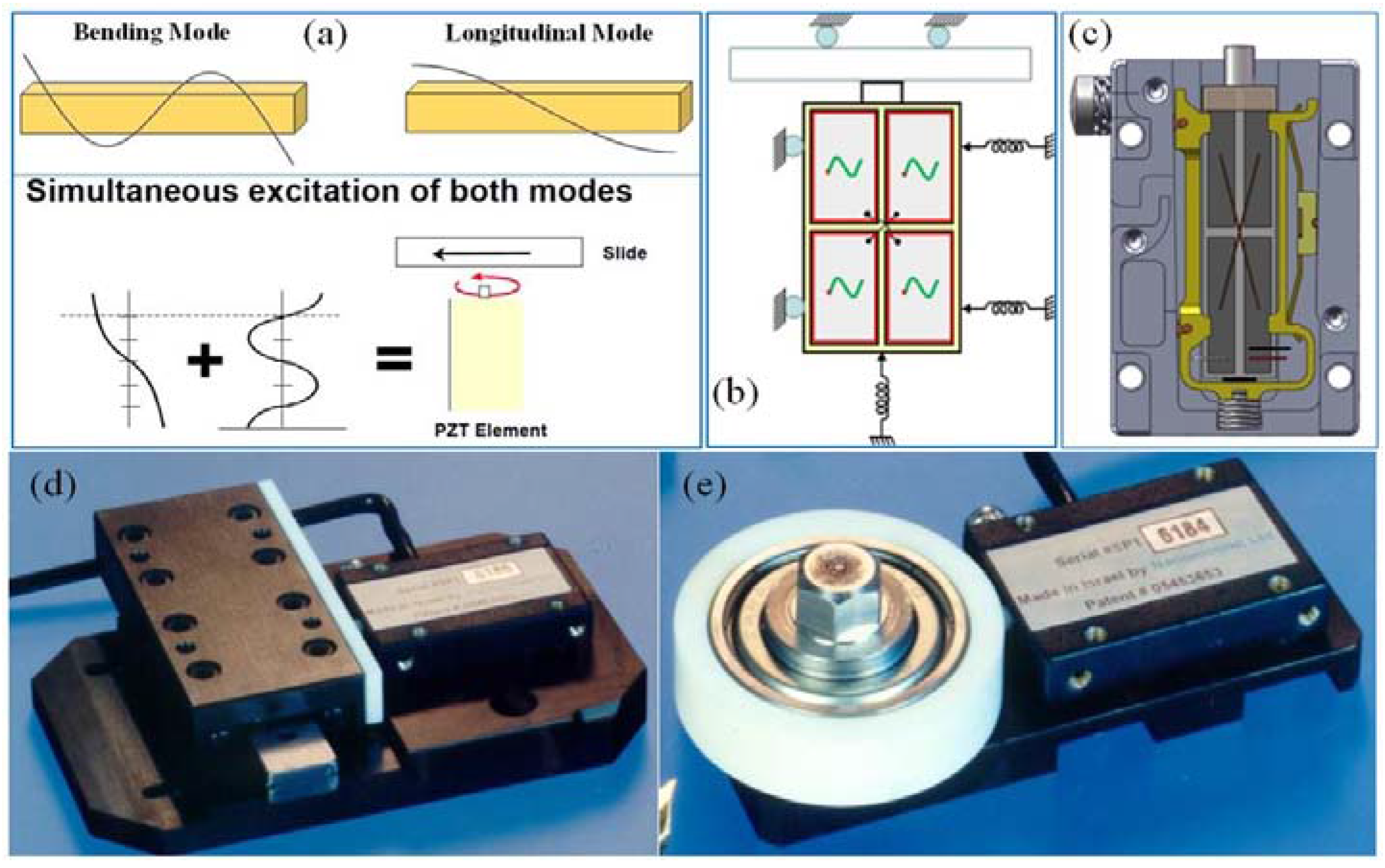
The basic motor design utilizes the length to width ratio of a rectangular piezoelectric bar, poled along the thickness direction, to excite a simultaneous vibration of the first longitudinal and the second bending resonance modes (both dependent on the bar’s length) (see Figure 2a). The vibration is excited in the length-width bar mid-plane (a plane perpendicular to the thickness direction), using the d31 piezoelectric coefficient.
The simultaneous vibration can be produced by two methods. The first method is selectively driving a chosen part of the element, using either one or two driving sources [8,9,10,11,12,13]. The second is adapting the element geometry to produce mode coupling [7]. In this paper we treat the first method only, since it is the one prevalent in industrial applications.
The two modes are excited together via the application of an AC electric field over the bar thickness, using a set of rectangular electrodes applied to the two largest bar faces: four quadrant electrodes (of the same size) over one face and a single large electrode over the other. Applying the field between the bottom electrode and one of the pairs of diagonally positioned electrodes on the top face (so only half of the piezoelectric volume is excited) excites both bending and extension in the bar midplane. Choosing the proper length-to-width ratio, attuned to a suitable excitation field frequency, leads to a constant phase difference between the extension and bending modes (at resonance frequency) where, as a result, each of the smallest bar faces traverses an elliptical trajectory (in the bar midplane). To produce motion, the vibrating element is preloaded onto a moving stage (linear or rotary) using back and side springs, which are chosen to provide required motor force and side stiffness, respectively (Figure 2b). An example of such design is shown in Figure 2c. The choice of one or the other pair of diagonally positioned electrodes on the top face determines the direction of the bar’s elliptical trajectory and hence the direction of stage motion. Thus two-directional motion of the stage can be obtained from a single-phase electrical drive by simply changing the excitation quadrants.
To prevent wear of the piezoelectric element during motor operation, preloading is done through a wear resistant hard ceramic tip, which is attached at the center of the bar’s face that is facing the stage (Figure 2b). The tip can also be attached at other locations on the element; these designs are less common and are not treated in this paper (for example see [11]). A complementary wear-resistant strip is attached on the stage side. The type of motion—either linear or rotary—is determined by choosing, accordingly, either a linear or a rotary stage (Figure 2d,e).
The force-velocity performance of the moving stage is determined by the amplitude and frequency of the tip’s elliptical motion, the element preloading forces, and the frictional properties of the tip-strip friction couple. The amplitude of the tip’s motion is proportional to the product of the electric field’s amplitude, the d31 piezoelectric coefficient, bar length and the mechanical resonance quality factor. Note that the resonance quality is much lower than that of a free body, due to damping caused by the preloading and the frictional energy losses of motor operation. The resonance frequency of motor operation is determined by the geometry, density and the elastic properties of the piezoelectric element.
The electric field driving the piezoelectric element (the motor) is produced via a resonance circuit, which converts a low voltage DC input into a high voltage AC output applied across the element.
Thus when compared to a typical, DC voltage-driven, piezoelectric actuator, the displacement obtained at the tip of the ultrasonic motor’s element, operating at resonance, is enhanced by two quality factors: that of the geometric mechanical resonance and that of the driving circuit electrical resonance. The typical displacements are in the micrometer range, which allows the input DC voltages to be lowered to the level of several tens of volts. The use of multilayer elements [14] allows the required DC input voltages to be further reduced to the level of several volts, allowing the use of batteries as the power source.
2.2. Motor Drive
The motor is driven by an AC sine wave produced using a voltage source resonant converter. The typical motor driver is constructed from several consecutive stages (see Figure 3a): (1) a DC converter, which is fed by an external DC power source; (2) an amplifier circuit which produces a PWM signal and (3) an LC resonant circuit (including the motor element as the capacitor) which produces the final AC sine wave on the element. Either two drive channels or a single channel, with a direction switch, are used to control the direction of motion, being connected to a different set of diagonal electrodes on the top face of the element (see Figure 3b).
Due to the stage static friction an inherent minimum level of AC motor voltage rms is required to initiate stage motion (this is the dead zone motor/driver voltage rms), after which the maximum attainable stage velocity increases linearly with increasing the motor voltage rms.
The above drive configuration exhibits high efficiency in converting low voltage DC input power into a high voltage AC drive, allowing the use of a small sized driver to power a large number of ultrasonic elements in parallel, either in a single motor or in a number of motors connected in parallel. This is especially beneficial for large scale motion solutions, such as the ones used in the semiconductor industry.
2.3. Motion Control
The motion controller provides a command voltage, typically between −10 V and 10 V, to the driver’s amplifier circuit. The driver translates the command voltage into a high voltage AC signal applied to the motor; thus a constant controller command voltage leads to a constant motor voltage rms. The minimum driver rms voltage to produce motion (dead zone driver voltage) translates accordingly into a minimum controller command value to produce motion (dead zone controller command value). The velocity as a function of time (of an initially idle stage) in response to a step function of constant controller command, which is higher than the dead zone controller command value, can be described by a first order differential equation in velocity. The solution yields a conversion to a maximum velocity value as function of time (for the corresponding command level) (see Figure 4) and a linear inverse relationship between stage velocity and available force (see Section 3.3 below). Hence, for a given constant command level (above dead zone) a stage with a moving mass, , can apply a maximum force (for that command level), , at zero velocity or achieve a maximum velocity, , with zero available force. The values of maximum force and maximum velocity increase with increasing command level, where the absolute maximum force (the stall force), , and the absolute maximum velocity, , values are achieved at a maximum command of 10V. The velocity time dependence, , can be well described by the relationship:
where is a time constant relating to motor dynamics. The values of and are determined by the piezoelectric properties, the resonance quality and the amplitude and frequency of the motor drive signal. also depends on: (1) the value of the normal force at the contact point between the hard ceramic tip and the drive strip, which is mainly determined by the preload applied by the back spring; (2) the number of L1B2 elements operated in parallel (in a single motor or several motors operating on the same motion axis). An example of stage dynamics in response to a step function of a constant controller command is shown in Figure 4, which shows the response of a linear stage with a moving weight of 235 g, driven by a Nanomotion HR2 motor, containing two L1B2 HR type driving elements (each providing a stall force () of 4 N), driven by a Nanomotion AB1A driver (see Figure 3). Figure 5a shows an example dependence of on the command level for Nanomotion HR motors.
Nanomotion has also developed a proprietary driver (AB5 driver) which eliminates the minimum motor voltage (and hence the minimum command level) requirement to initiate stage motion [16] and yields a linear relationship between controller command and stage velocity (see Figure 5b).
The typical closed loop motor control is executed using a high bandwidth PIV controller with a nonlinear mechanism. Figure 6 shows an example block diagram of a controller servo loop (Nanomotion XCD [18]), utilizing the following mechanisms to increase the precision of stage motion: (1) Offset mechanism—provides an initial command starting value to overcome the inherent dead zone; (2) Zero Feed Forward mechanism—improves the stage settling time by stopping the velocity control loop (typically 30 to 50 µm before target position) and thereby reducing the speed at which the stage approaches its target position and eliminating overshoot; (3) Dead Zone mechanism—takes advantage of the motor intrinsic friction to prevent jitter and improve settling time. It is realized by defining two position ranges around the target position. The smaller range (DZMIN) defines a small position range around the target. When the motor enters this range, the controller drops the command to zero but continues to monitor position. Only if the position leaves a certain (desired) predefined higher range (the required accuracy) around the target (DZMAX) does the control loop restart to correct.
3. Operational Conditions
3.1. Temperature Range
Since many of the piezoelectric materials suitable for use in high power piezoelectric motors have Curie temperatures above 300 °C, the Curie temperature itself usually does not serve as a temperature limit to motor operation (from a purely piezoelectric properties point of view, as a rule of thumb, the motor should not be operated above half the Curie temperature (in degrees Celsius) to ensure minimal change in the piezo properties). With respect to both high and low temperature operation limits one needs to account for: (1) the changes in the material properties of the piezoelectric element, which may affect the resonance frequency as well as the magnitude of the piezoelectric coefficient; (2) thermal expansion mismatch between the different motor parts and the resulting thermal stress; (3) the change in the mechanical properties of motor components, such as the glass transition temperatures of adhesives and engineering plastics and the solidus temperatures of solder joints. Currently L1B2 motors operating between −20 °C and 50 °C are available (Nanomotion HR motors), where with the use of special materials this range can be expanded further to cover from −55 °C to 80 °C (Nanomotion Edge and Edge4X motors) and more.
3.2. Vacuum Operation
Due to the inherently low outgassing properties of piezoelectric ceramics, piezoelectric ultrasonic motors are well suited to operate in high vacuum. The design of a vacuum motor needs to account for the vacuum outgassing of all motor parts exposed to vacuum conditions, typically employing low outgassing metals and engineering plastics, as well as vacuum compatible adhesives (for example see [19]). In high vacuum motors, it is generally a good practice to limit the use of plastics and adhesives to a minimum. Table 1 shows an example breakdown by weight of a high vacuum compatible L1B2 motor (Nanomotion HR4-1-U-1.5 UHV) into material types. Note that the combined weight of adhesives and elastomers is only 0.14% of the total motor weight. To further increase vacuum compatibility, special cleaning and vacuum baking techniques should be employed.
3.3. Envelope of Performance
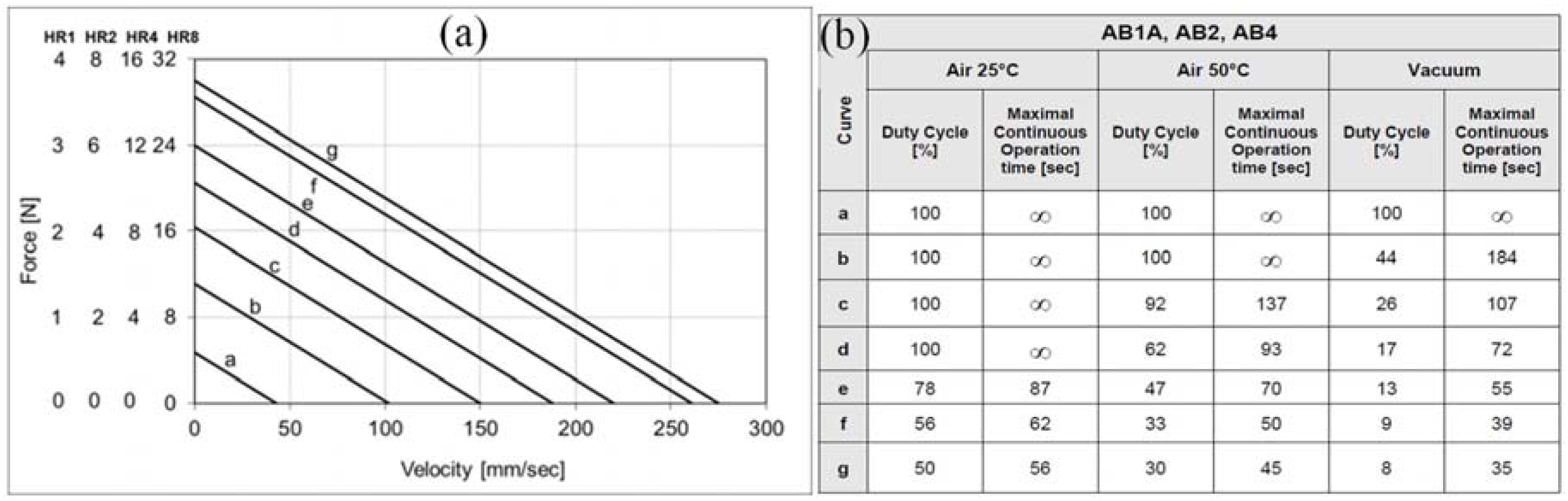
The ergonomic nature of the L1B2 solution allows several L1B2 elements to be combined in a single motor to increase the driving force and motor stiffness in the direction of motion. Nanomotion HR type motors employ this feature, offering 4 N of stall force per a single L1B2 HR type drive element (HR1 motor), 8 N for two elements (HR2 motor), 16 N for four (HR4 motor) and 32 N for eight (HR8 motor) [17]. Their envelope of performance, explained in the following paragraph, is shown in Figure 7.
The duration of the motor’s continuous operation is limited by the need to balance the rate of heat generation by the element, while it operates, with the rate of heat dissipation to the environment; the dissipation rate depends on the element temperature, the environmental temperature and the heat conductivity of motor and stage components. The resulting motor operation temperature must not exceed the material limitations of motor components. When those limits are approached (to within a given safety factor) motor operation must be stopped and the motor given time to cool down. As a result, for each set of operational conditions, consisting of a combination of force, velocity and environment type, there exists a maximal duty cycle, which is defined as a maximal percent of operational time out of the total (operational plus idle) time. An example maximal allowable duty cycle, for Nanomotion HR type motors driven by AB1A driver, is shown in Figure 7b: for air environment at 25 °C and 50 °C, and for high vacuum at 25 °C. The complementing operational conditions are shown in Figure 7a.
3.4. Friction and Wear Considerations
The use of friction drive by the L1B2 motor imposes stringent requirements on the material properties of the friction pair. A high stiffness for both the tip and strip is required to facilitate high positioning precision with a fast move and settle. The friction coefficient must be high enough to provide the forces required by the intended application. It must remain constant to within a small tolerance throughout the lifetime of the application, to facilitate smooth motor operation. The wear rate of both the tip and strip must remain low to negligible throughout the lifetime of the application.
The combination of the above requirements is not straightforward and typically requires a research and development effort into the tribological aspects of the tip-strip contact. For example the use of lubricants to obtain low wear is typically limited by the friction coefficient requirement. This increases the importance of the bulk material parameters in wear prevention. The value of the friction coefficient might also be affected by the chemistry of the environment the motor is operating in (e.g., ambient, high vacuum, vapor deposition chamber, etc.).
In view of the above, the optimization of L1B2 motor operation must be supported by a base of tribological knowledge, gathered through a dedicated research and development effort, focused on the material and environmental aspects of the intended application. To ensure reliability, each chosen friction pair should be tested by motor operation under the conditions of the intended application. Nanomotion has gathered hundreds of months of operating motors, optimizing friction pairs to be used at various environments and operating conditions. The suitable materials are typically chosen from the family of hard ceramics.
4. Positioning Accuracy
Let us consider a linear stage coupled to an L1B2 motor as shown in Figure 2b. The stage moving mass is coupled to the stationary motor casing through the elastic components housing the L1B2 elements (see for example Figure 2c). Thus the stage moving mass effectively acts as a mass on spring along the direction of motion, with a corresponding resonance frequency proportional to the square of the effective stiffness of the elements’ housing. On one hand this setup produces a low pass filter, which, for a typical stage, does not allow stage motion frequencies in the ultrasonic range. Thus, the position error during motion does not directly depend on a single ultrasonic vibration. On the other hand this resonance frequency puts an upper limit on stage dynamics. As a result, a high stiffness of element housing (the effective motor stiffness in the direction of motion) is an important factor in achieving fast move and settle dynamics with high positioning precision.
The positioning accuracy of stages, driven by L1B2 ultrasonic motors via a closed loop control, depends on several factors: the effective motor/s stiffness in the direction of motion, the gains and the frequency of the close loop control algorithm, the position resolution of the feedback mechanism and the magnitude of ultrasonic vibrations. In the next example we show that for a typical 0.5 kg stage an accuracy of several tens of nanometers is readily available.
In addition to stage motion generated by ultrasonic vibrations (AC mode motion) the L1B2 elements can be used in actuator mode—where after switching off the ultrasonic resonance mode, the final position is attained and held by a close loop controlled DC voltage that is applied across the element causing it to bend (DC mode motion), thereby moving the stage in a sub-micron range [20]. This mode allows reaching a sub-nanometer resolution given a suitable resolution of position feedback.
Figure 8 and Figure 9 show examples of linear stage motion via an L1B2 motor—a Nanomotion HR8 motor, with a motor stiffness of 3.5 N/µm. Figure 8 shows an example of a high accuracy AC mode positioning of a 0.5 kg stage. The system performed repetitive back and forth 10 mm movements, repeatably settling within 90 ms, to a 50 nm window. Figure 9 shows an example DC mode actuation of horizontal stage having a 2 kg moving weight, within a maximum actuation range of 600 nm (Figure 9a) as well as an example of a 4 nm step (Figure 9b) with the position held to within 1 nm accuracy before and after the step. The measurements were taken on a very rudimentary vibration suppression table, the environmental vibrations are suppressed by the high motor damping.
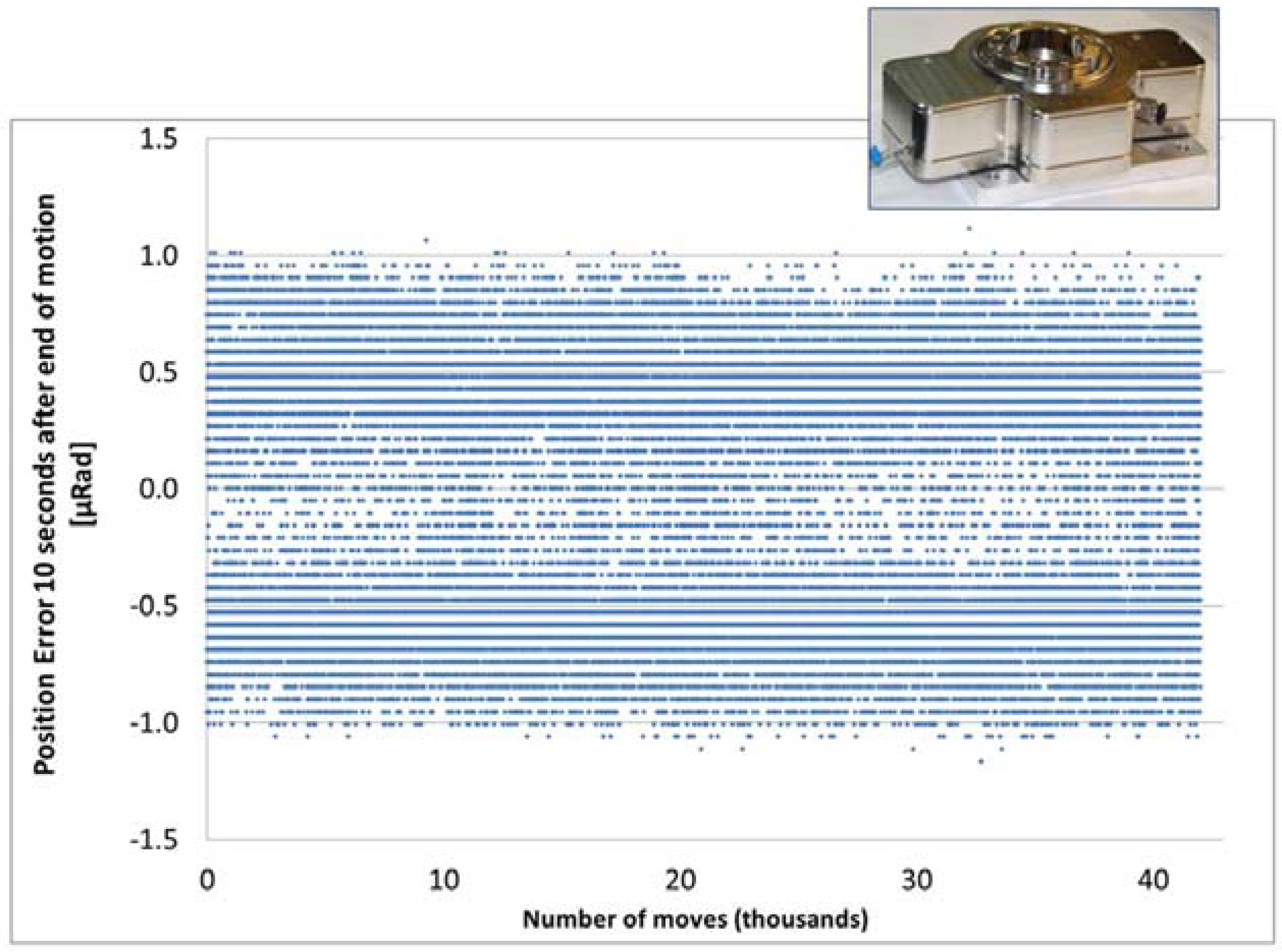
Operating an L1B2 motor over a drive ring equipped with a high resolution encoder allows a rotary axis to be constructed with a very high angular accuracy. An example is shown in Figure 10, which details the position error of a NM FBR60 rotary stage (driven by two Nanomotion HR2 vacuum motors) over more than 42,000 steps of 90°. A typical position error, 10 seconds after the end of motion is less than 1 micro-radian.
5. Examples of Motion Solutions
5.1. Vacuum Stages for Space Applications
The use of L1B2 motors holds several advantages for space applications. Having a direct drive allows L1B2 motors to provide high force/torque at low speeds, eliminating the need for gear (which is typically used in combination with DC motors to obtain high torque at low speeds), freeing up design weight and volume and eliminating backlash. The zero power consumption when holding position eases the power requirements, while low outgassing reduces the risk of contamination.
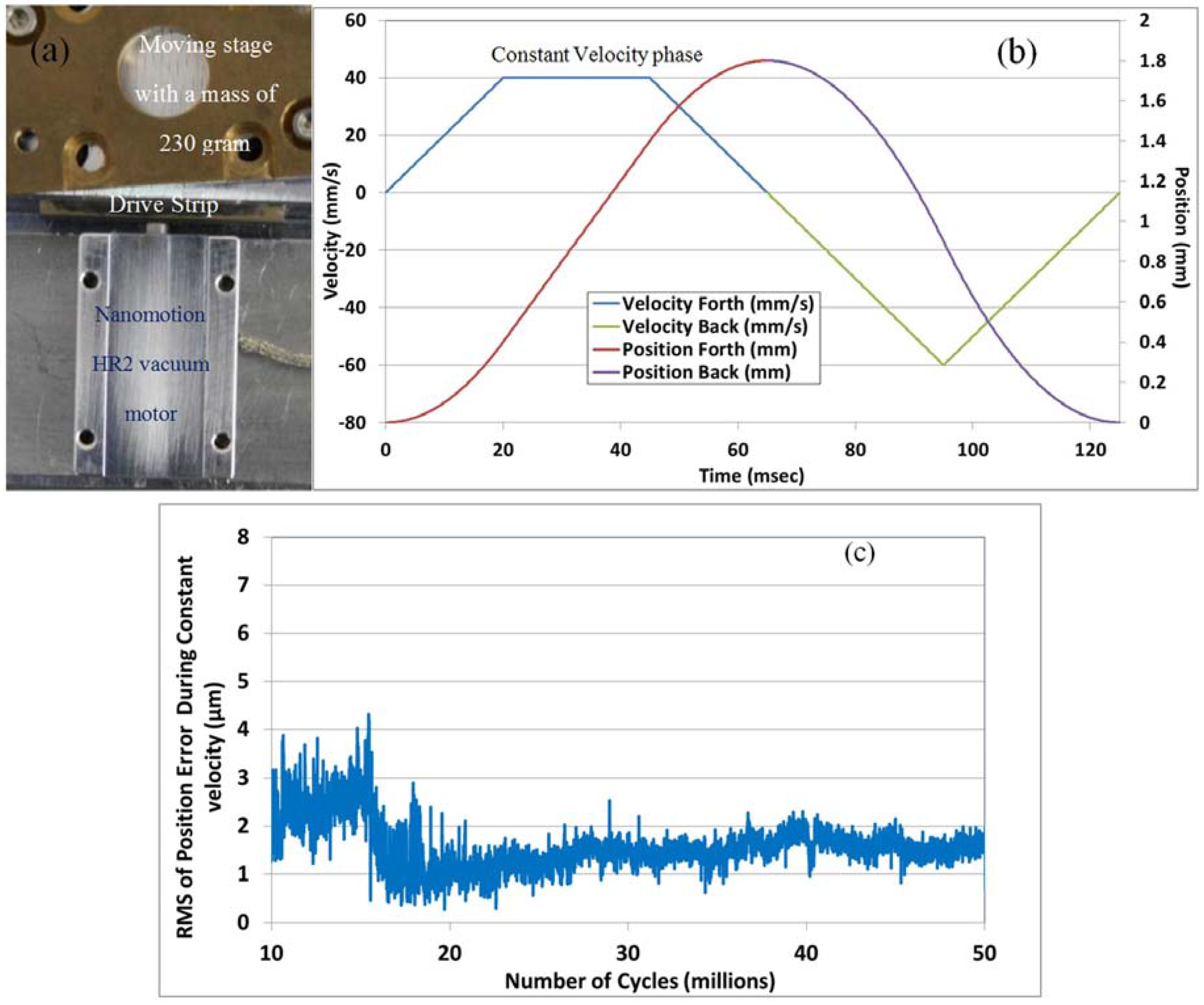
Figure 11 shows an example L1B2 motor based miniature scanning stage, for use in low earth orbit (LEO) conditions. The motor is an HR2 vacuum motor, driven and controlled by an XCD controller driver [21]. The motor drives a linear stage having a moving weight of 230 g. The system has been tested in a high vacuum (10−6 Torr) while continuously performing a periodical motion profile at a frequency of 8 Hz (Figure 11b). The profile presents a high duty cycle operation including accelerations of 2 m/s2. The average position error rms during the constant velocity phase of motion has remained below 4 µm during 50 million cycles of operation in vacuum (Figure 11c). This test simulates 3 years of space operation in high vacuum.
To ensure negligible molecular outgassing, all of the motor and stage components need to pass stringent vacuum cleaning procedures. As an example, Figure 12 presents a residual gas analysis scan of a Nanomotion FBR60-U stage idle in a high vacuum (with active pumping). The scan was performed on an as cleaned stage, 60 h after the start of vacuum pumping. A comparison of the obtained spectrum to that of the chamber baseline does not indicate the presence of any gas partial pressure lines, having a partial pressure above that of test sensitivity (5E-11 Torr), which may be attributable to the stage outgassing.
5.2. Semiconductor Market
L1B2 motors can successfully address the requirements for clean room wafer handling, operating inside production and analytical instruments. The use of a resonant drive method allows the operation of multiple elements in parallel, thereby increasing the available forces to drive heavy loads. For example, a Nanomotion AB1B driver can drive up to 64 elements (or 8 HR8 type motors) per drive axis, reaching a combined stall force of 256 N. Compound multi-axis solutions provide fast move and settle moves over large distances and arbitrary orientations. Examples shown in Figure 13 include stages for metrology and microscopy.
5.3. Biomedical Applications
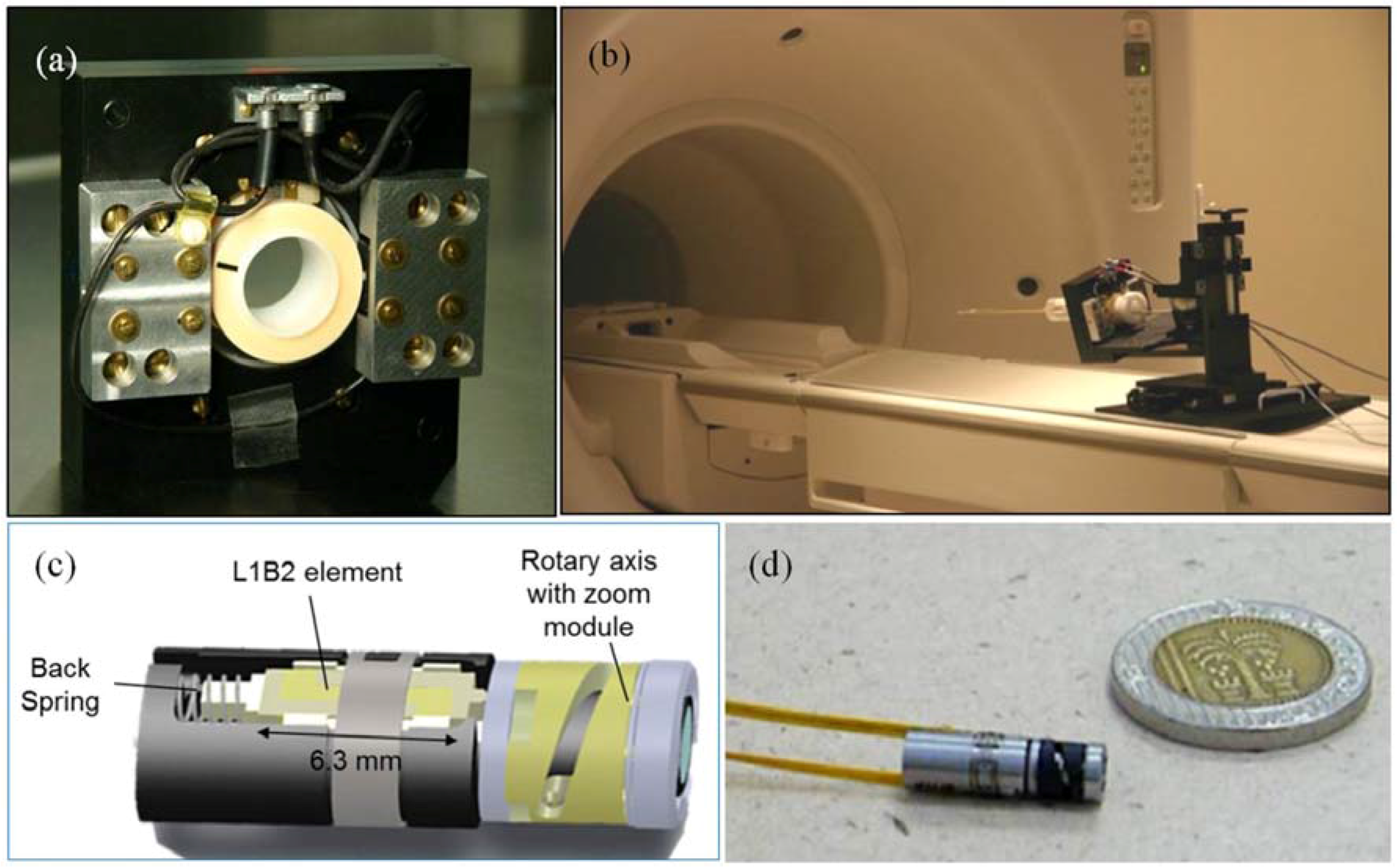
The unique advantages of L1B2 motors make them attractive for use in biomedical devices. The extremely low magnetic signature (0.1 nT and a recovery time of less than 3 ms) allows operation inside MRI instruments. Figure 14a,b shows an example application where two Nanomotion HR2-V motors are used to rotate a shaft operating inside an MRI instrument with a magnetic field of 3 Tesla.
The high torque to size ratio and short response times allow solutions to be designed for moving small medical and electro-optical devices. An example of a miniature zoom module for endoscopy tool is shown in Figure 14c. This module is based on a small, 6.3 mm long L1B2 element, designed to operate at a low motor voltage of 10 V rms, enabling operation in vivo. Maximum rotation torque is 0.5 mN·m. Maximum angular velocity is 30 rad/s. This zoom module has a total weight of 1.4 g and is equipped with a miniature camera with a diameter of 1.2 mm.
5.4. Electro-Optics Modules
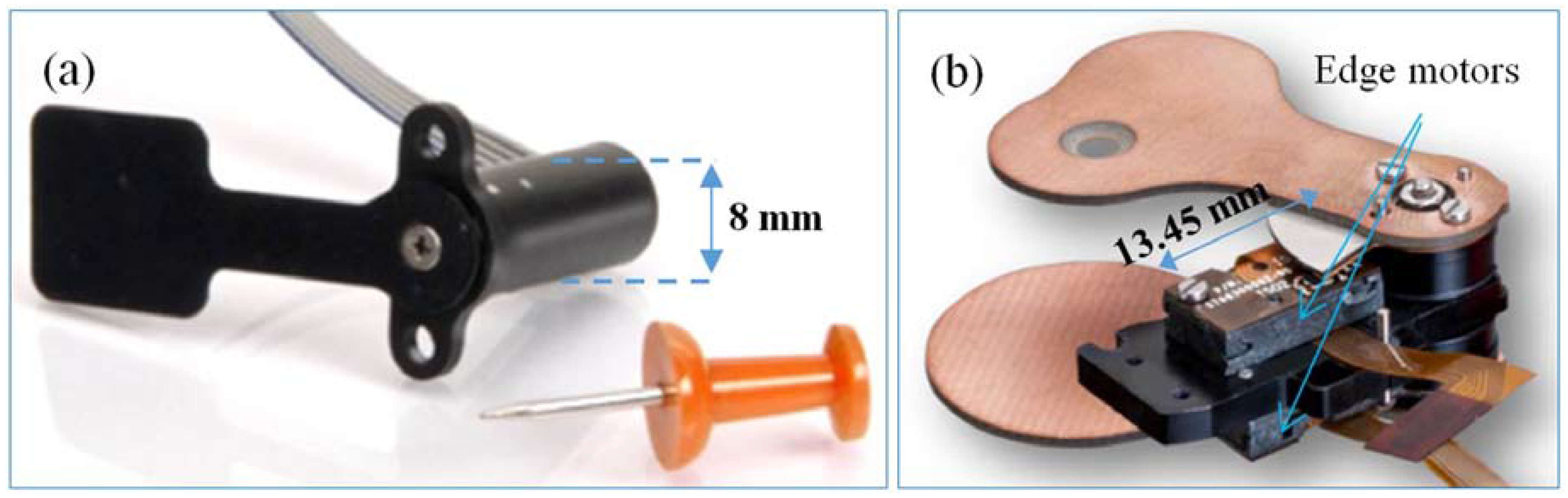
When used in small electro-optical modules L1B2 motors provide fast accurate motion while providing favorable size weight and power (SWaP) characteristics (small size and weight along with low power consumption). Example applications—Non Uniformity Correction (NUC) shutters, for uncooled IR camera and laser applications—are shown in the figures below. All of the shutters are based on a Nanomotion Edge type motor [22], which is based on a 9 mm long L1B2 element providing a maximum velocity above 200 mm/s, a maximum (stall) force above 0.35 N and a motor stiffness above 0.06 N/µm. An example linear shutter is shown in Figure 15. It has a total weight of 15 g (moving weight equals 1.5 g), an aperture area of 14.7 × 17.0 mm2 and a stroke (open/close) time of 150 ms. Rotary shutter modules are shown in Figure 16. A single axis module, shown in Figure 16a, weighs 2 g in total and has the ability to perform a 90° turn in less than 50 ms. A two axis module, shown in Figure 16b can independently rotate each of the two shutter leafs, each weighing about 2 g, performing a 60° turn within 100 ms.
6. Summary
The precise motion solutions based on L1B2 ultrasonic motors are able to provide a positioning accuracy in the nm range, while offering high forces and large dynamic ranges in velocity, thereby accomplishing a fast move and settle throughput, over large travels, in a single mechanism. The complete motion solution consists of a motor, a driver, a moving platform, and a motion controller operating a closed servo loop using a position feedback sensor. All of these parts can be adapted to meet a specific application in the fields of semiconductor metrology, aerospace, biomedical and electro-optics.
In the metrology field, the advantage of a high throughput is key, based on a fast move and settle and an unlimited travel. In multiple motion axes employed to meet 3D positioning requirements, the L1B2 motor yields significant weight benefits. Clean room environmental conditions are feasible, as the core piezo element is UHV compatible and no lubrication is required. The system UHV compatibility is met by using verified materials in combination with advanced cleaning techniques.
In the fields of aerospace and electro-optics, the advantages of inherently high power density, energy efficiency at small size and low power consumption, coupled with ergonomic design and the absence of gear, allow favorable SWaP parameters (size weight and power) to be preserved.
For biomedical applications, low magnetic signature allows operation in medical devices with high magnetic fields, while a small footprint is favorable for endoscopy applications.
Ongoing work on the L1B2 motors at Nanomotion is aimed to broaden the performance envelope and the realm of applications.
Acknowledgments
The authors acknowledge partial support by the Office of the Israeli Chief Scientist and specifically the MAGNET Metro450 consortium.
Conflicts of Interest
The authors declare no conflict of interest.
References
- Uchino, K. Piezoelectric ultrasonic motor: Overview. Smart Mater. Struct. 1998, 7, 273–285. [Google Scholar] [CrossRef]
- Sashida, T.; Kenjo, T. An Introduction to Ultrasonic Motors; Clarendon Press: Oxford, UK, 1993. [Google Scholar]
- Nanomotion Ltd. Motion Systems. Available online: http://www.nanomotion.com/product-type/motion-systems/ (accessed on 11 April 2016).
- Wiwattananon, P.; Bryant, R.G. Performance Comparisons and Down Selection of Small Motors for Two-Blade Heliogyro Solar Sail 6U CubeSat. NASA Technical Report NASA/TM–2015-218784. 2015. Available online: http://ntrs.nasa.gov/search.jsp?R=20150017043 (accessed on 11 April 2016). [Google Scholar]
- Uchino, K. Introduction to Piezoelectric Actuators and Transducers. Defense Technical Information Center Document ADA429659. 2003. Available online: http://www.dtic.mil/cgi-bin/GetTRDoc?AD=ADA429659 (accessed on 11 April 2016).
- Hemsel, T.; Mracek, M.; Twiefel, J.; Vasiljev, P. Piezoelectric linear motor concepts based on coupling of longitudinal vibrations. Ultrasonics 2006, 44, e591–e596. [Google Scholar] [CrossRef] [PubMed]
- Aoyagi, M.; Tomikawa, Y. Ultrasonic motor based on coupled longitudinal-bending vibrations of a diagonally symmetric piezoelectric ceramic plate. Electron. Commun. Jpn. 1996, 79, 60–67. [Google Scholar] [CrossRef]
- Tsai, M.S.; Lee, C.H.; Hwang, S.H. Dynamic modeling and analysis of a bimodal ultrasonic motor. IEEE Trans. Ultrason. Ferroelectr. Freq. Control 2003, 50, 245–256. [Google Scholar] [CrossRef] [PubMed]
- Zumeris, J. Ceramic Motor. U.S. Patent No. 5,453,653, 26 September 1995. [Google Scholar]
- Ganor, Z.; Shiv, L.; Karasikov, N.; Avital, A. Piezoelectric Motors and Motor Driving Configurations. U.S. Patent No. 6,979,936 B1, 27 December 2005. [Google Scholar]
- Tomikawa, Y.; Takano, T.; Umeda, H. Thin rotary and linear ultrasonic motors using a double-mode piezoelectric vibrator of the first longitudinal and second bending modes. Jpn. J. Appl. Phys. 1992, 31, 3073–3076. [Google Scholar] [CrossRef]
- Guo, M.; Dong, S.; Ren, B.; Luo, H. A double-mode piezoelectric single-crystal ultrasonic micro-actuator. IEEE Trans. Ultrason. Ferroelectr. Freq. Control 2010, 57, 2596–2600. [Google Scholar] [PubMed]
- Li, X.; Chen, J.; Chen, Z.; Dong, S. A high-temperature double-mode piezoelectric ultrasonic linear motor. Appl. Phys. Lett. 2012, 101, 072902. [Google Scholar] [CrossRef]
- Ganor, Z.; Rafaeli, I.; Shiv, L.; Karasikov, N. Multilayer Piezoelectric Motor. U.S. Patent No. 7,075,211 B1, 11 July 2006. [Google Scholar]
- Nanomotion Ltd. AB1A Driver User Manual. Available online: http://www.nanomotion.com/wp-content/uploads/2015/01/AB1A458000-00-User-Manual-AB1A1.pdf (accessed on 11 April 2016).
- Nanomotion Ltd. AB5 and AB51 Drivers User Manual. Available online: http://www.nanomotion.com/wp-content/uploads/2015/05/AB05458200-02-User-Manual.pdf (accessed on 11 April 2016).
- Nanomotion Ltd. User Manual HR Motors. Available online: http://www.nanomotion.com/wp-content/uploads/2015/09/HR00458000-00-HR-Motor-User-Manual.pdf (accessed on 11 April 2016).
- Nanomotion Ltd. XCD Software Version 1.4.0.7. Available online: http://www.nanomotion.com/wp-content/uploads/2014/05/XCD-software-version-1-4-0-7.pdf (accessed on 11 April 2016).
- Outgassing Data for Selecting Spacecraft Materials Online. Available online: https://outgassing.nasa.gov/ (accessed on 11 April 2016).
- Ganor, Z. High Resolution Piezoelectric Motor. U.S. Patent No. 7,061,158 B2, 13 June 2006. [Google Scholar]
- User Guide XCD-HR Controller/Drivers. Available online: http://www.nanomotion.com/wp-content/uploads/2015/05/XCDH458002-00-XCD-HR-Contr-Driver-UM_.pdf (accessed on 11 April 2016).
- Nanomotion Ltd. Edge Motor. Available online: http://www.nanomotion.com/motion-product/edge-motor/ (accessed on 11 April 2016).
Figure 1.
Schematic representation of the architecture of a precise motion solution, based on an L1B2 ultrasonic motor.
Figure 1.
Schematic representation of the architecture of a precise motion solution, based on an L1B2 ultrasonic motor.
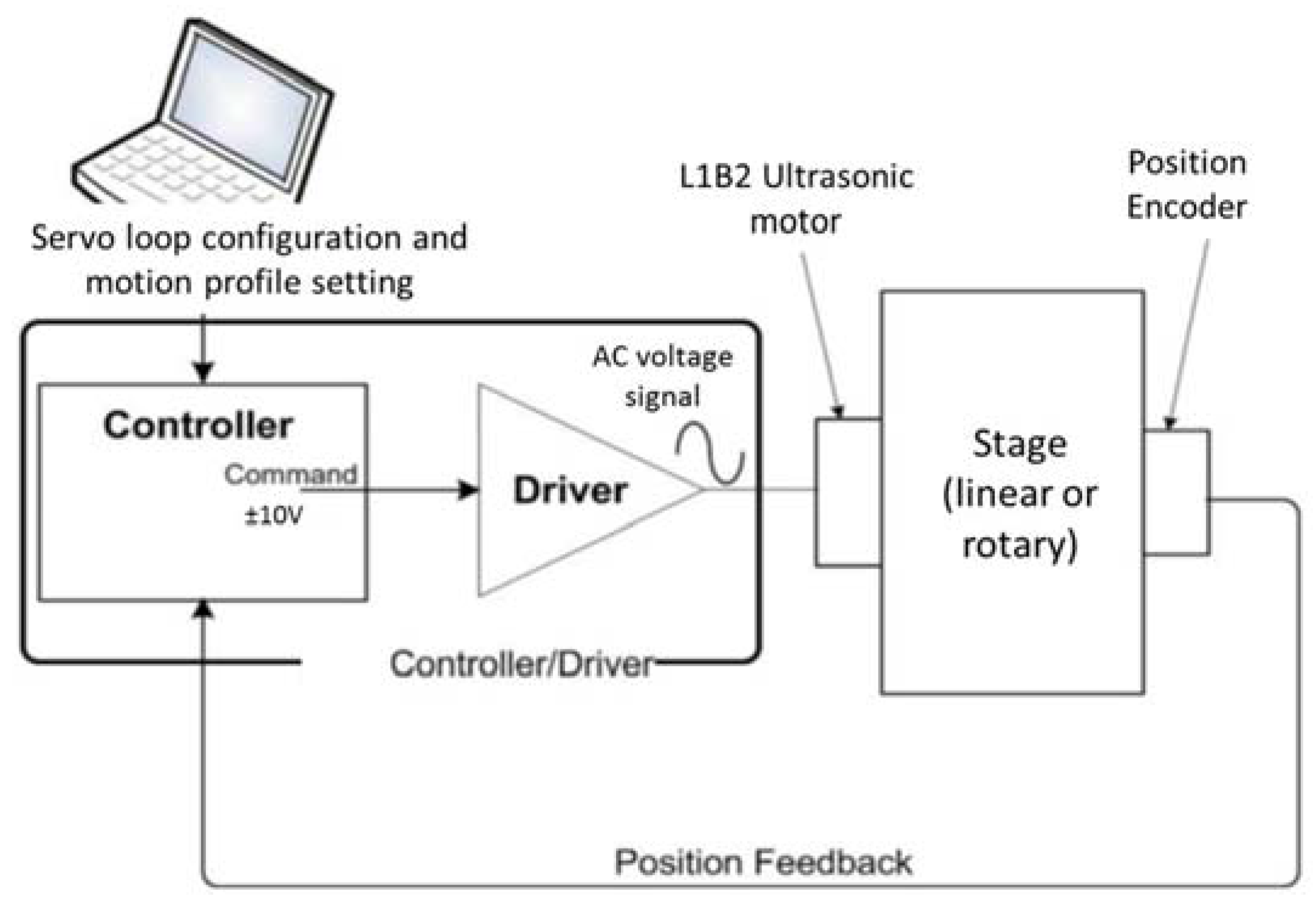
Figure 2.
Basic design of an L1B2 piezoelectric ultrasonic motor: (a) Schematic representation of a simultaneous excitation of longitudinal and bending modes; (b) Schematic drawing of the preloading of a piezoelectric element onto a moving stage; (c) Example drawing of a Nanomotion HR1 type motor, based on a single L1B2 (Nanomotion HR type) piezoelectric element, implementing the element preloading scheme that is schematically shown in (b); (d) Image of a linear stage driven by a Nanomotion HR1 motor; (e) Image of a rotary axis driven by a Nanomotion HR1 motor.

Figure 3.
Schematic representation of an ultrasonic motor driver design (Nanomotion AB1A driver [15]): (a) Main driver stages; (b) Diagram of the output stage with an internal LC card (single channel with a direction switch).
Figure 3.
Schematic representation of an ultrasonic motor driver design (Nanomotion AB1A driver [15]): (a) Main driver stages; (b) Diagram of the output stage with an internal LC card (single channel with a direction switch).
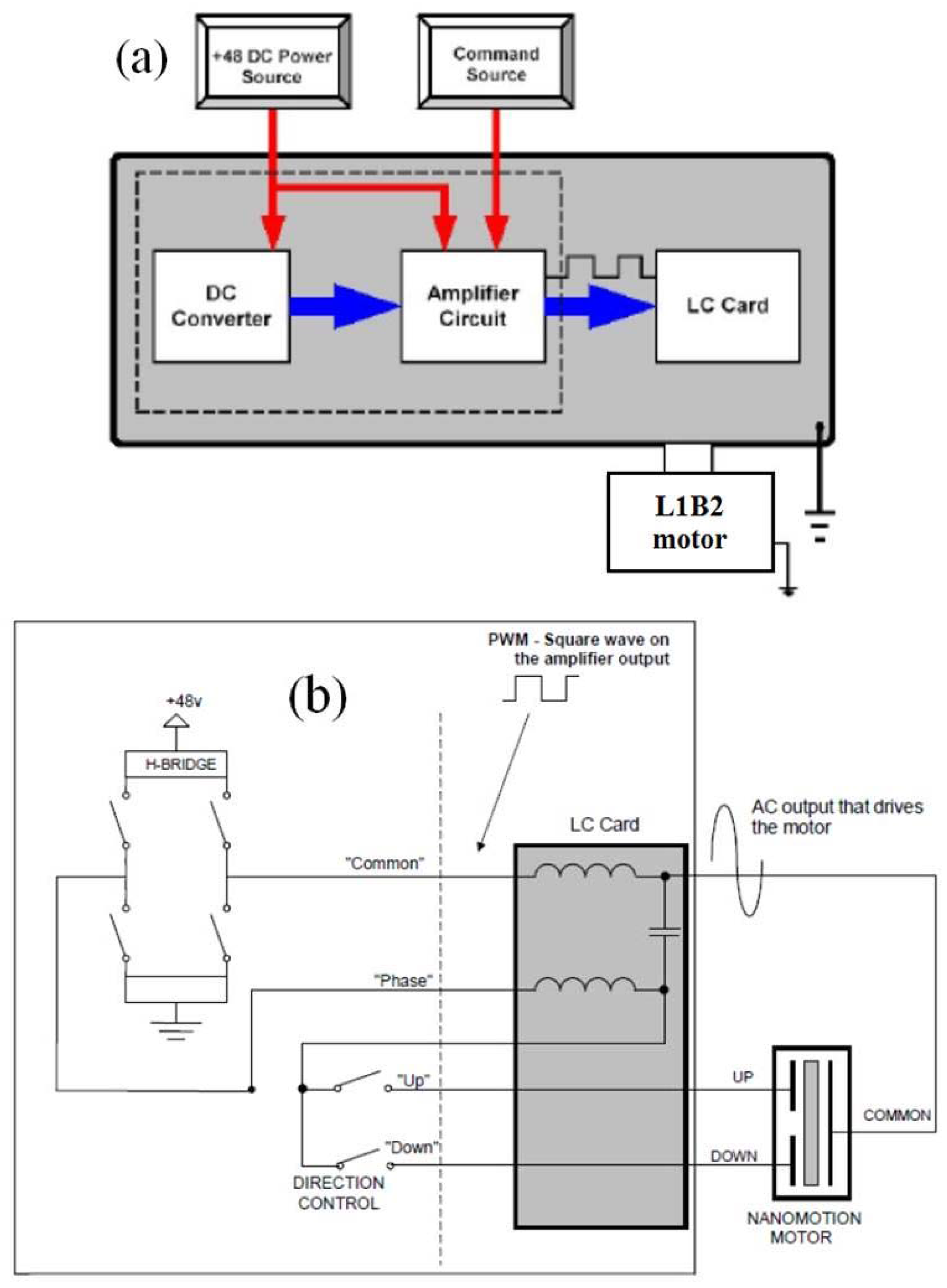
Figure 4.
Stage velocity as function of time for several values of constant controller command applied to the driver; the motor is Nanomotion HR2, moving a horizontal linear stage with a moving mass of 235 g. The driver is Nanomotion AB1A.
Figure 4.
Stage velocity as function of time for several values of constant controller command applied to the driver; the motor is Nanomotion HR2, moving a horizontal linear stage with a moving mass of 235 g. The driver is Nanomotion AB1A.
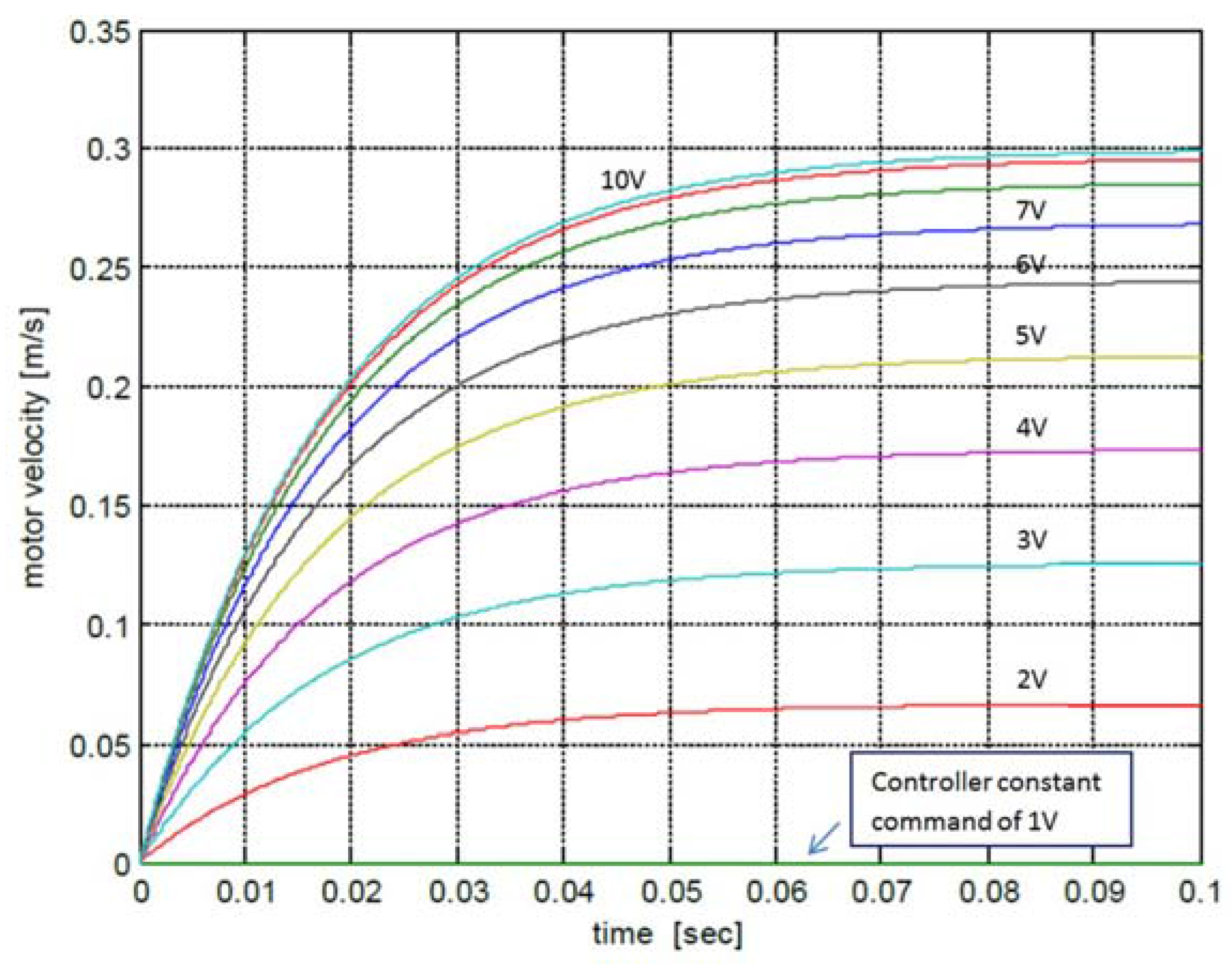
Figure 5.
Linear stage maximum velocity as function of controller command voltage applied to the driver. The values are for L1B2 motors (Nanomotion HR-Type [17]) driven by Nanomotion drivers AB1A (a) and AB5 (b). The motors operate horizontally at room temperature and low duty cycle (<10%). The motor interface is with a ceramic strip and a cross-roller high quality slide.
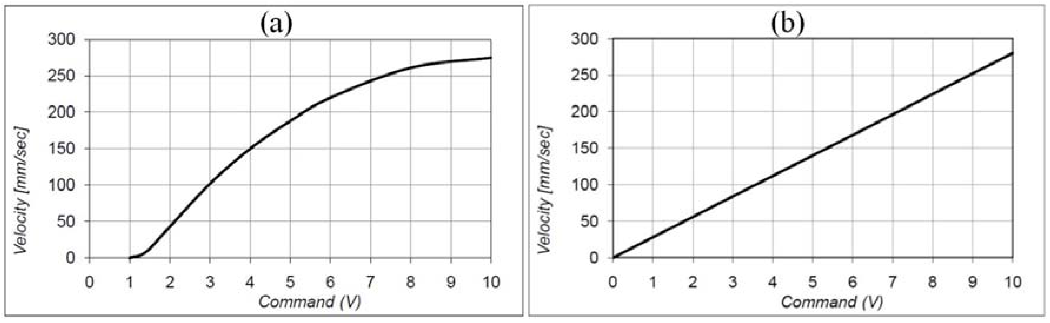
Figure 6.
Motion controller servo loop block diagram (Nanomotion XCD controller [18]).
Figure 6.
Motion controller servo loop block diagram (Nanomotion XCD controller [18]).
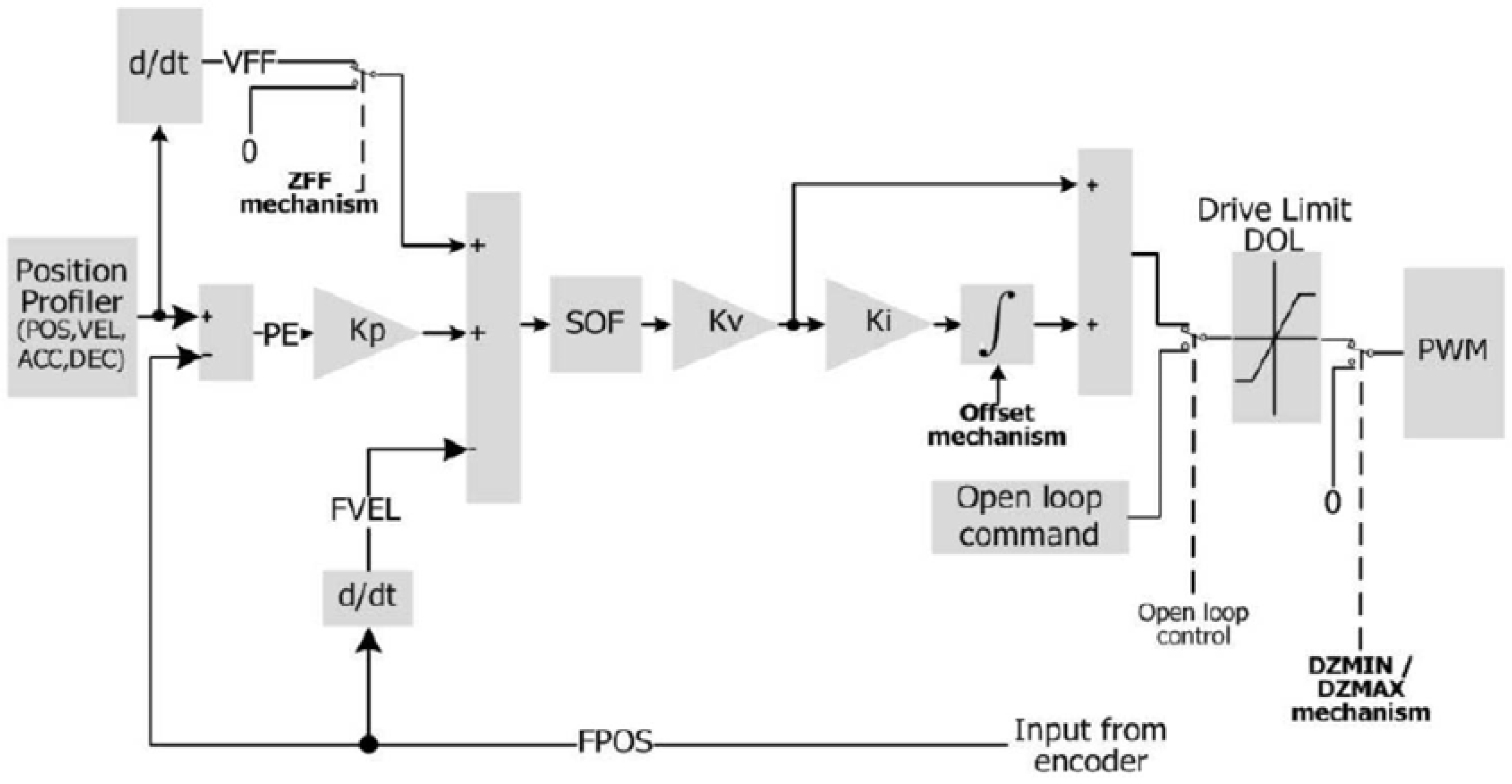
Figure 7.
Envelope of performance of L1B2 motors from Nanomotion HR motor series, when driven by AB1A driver [17]: (a) Force—velocity curves, for Nanomotion HR-type motors; (b) maximal duty cycle for operation in air and vacuum, for operating at force-velocity combinations, located below each of the force velocity curves shown in (a).

Figure 8.
Example of high accuracy fast positioning, using an, L1B2 motor based, linear motion stage, with a moving weight of 0.5 kg. The performance shown is of a NM stage FB75-100-HR8 driven by a NM HR8-V vacuum motor (containing eight L1B2 elements) and equipped with an optical encoder position feedback (encoder resolution is 10 nm). The red colored graphs are all taken with an external reference encoder having a resolution of 0.1 nm. (a) An image of the FB75-100-HR8 stage; (b) Stage position and velocity as function of time, showing a typical 10 mm motion step, accomplished within 300 ms; (c) Feedback position during break, showing a (complete break) settling to a window less than 50 nm from target within 100 ms, followed by a landing drift of less than 15 nm during the next 3 s; (d) Position as function of time during sequential back and forth 10 mm moves. The graph focuses around the landing position at one of the two motion ends, showing a landing repeatability window of less than 50 nm.

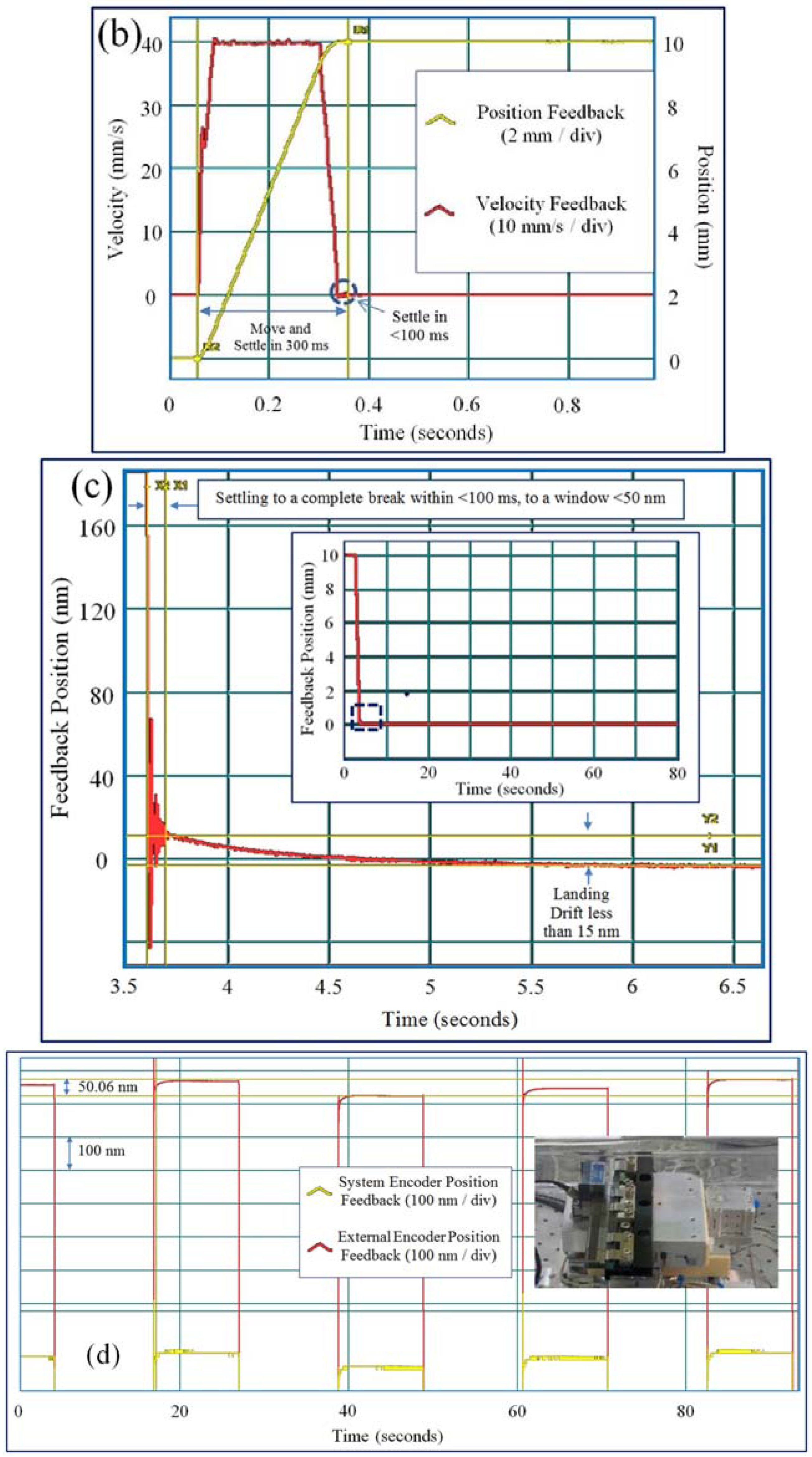
Figure 9.
The use of an L1B2 motor in actuator (DC) mode. (a) The motion of a linear stage with a moving weight of 2 kg, driven by a NM HR8 motor (containing eight L1B2 elements) operating in a DC mode: position and controller command level as function of time; (b) Example of a 4 nm position step, performed with a Nanomotion FB75-100-HR8 stage operating in DC mode, equipped with a NM HR8 motor. The resolution of the feedback position encoder is 0.4 nm.
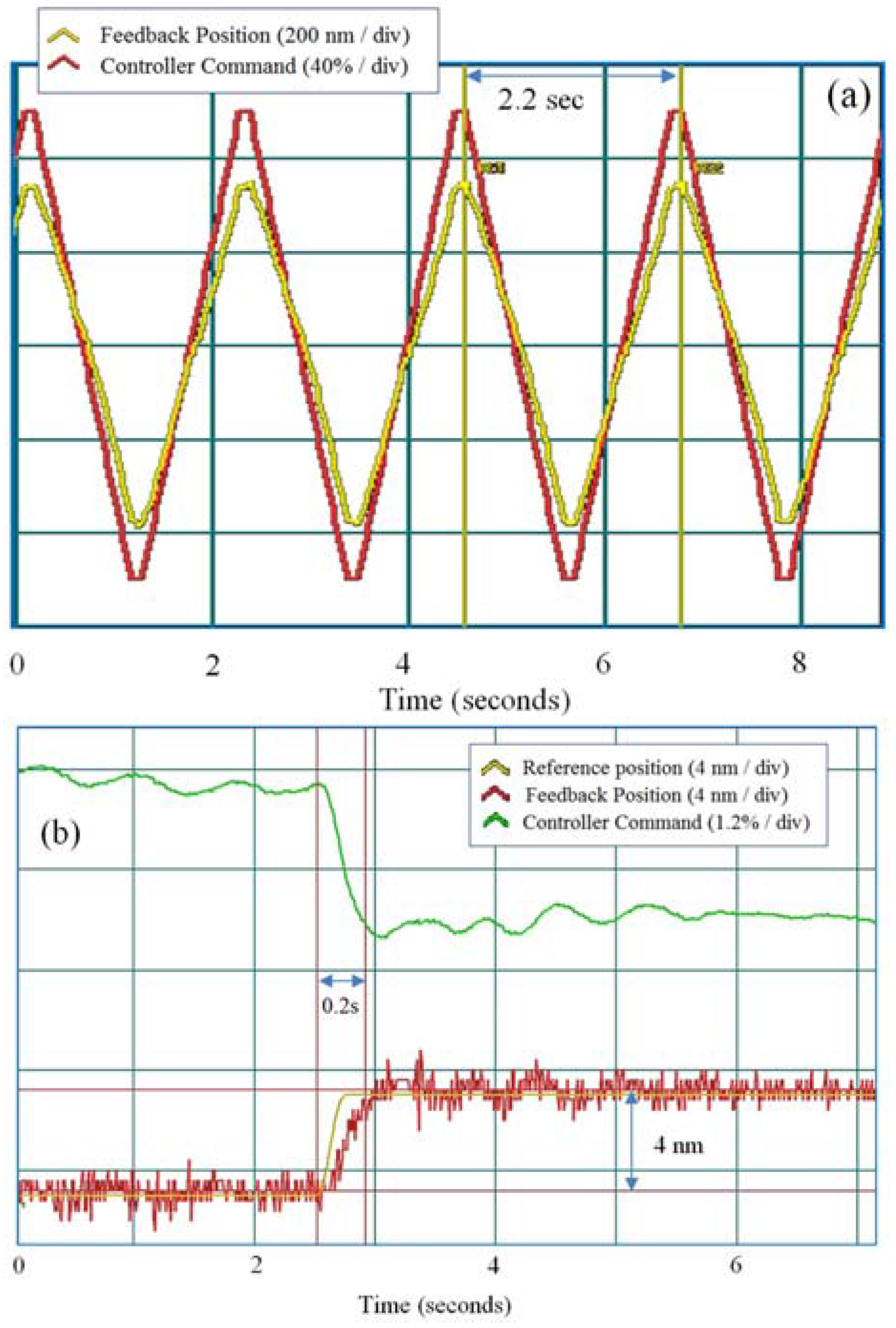
Figure 10.
Positioning accuracy of a rotary stage (Nanomotion FBR60 stage, shown in the inset) operated by two L1B2 motors (Nanomotion HR2 vacuum motors). The stage was operated in consecutive 90° steps (each four steps completing a rotation cycle). The angular position error for each step was recorded 10 s after the end of motion and is represented by a point on this graph that shows the recorded position errors for 42,000 steps.

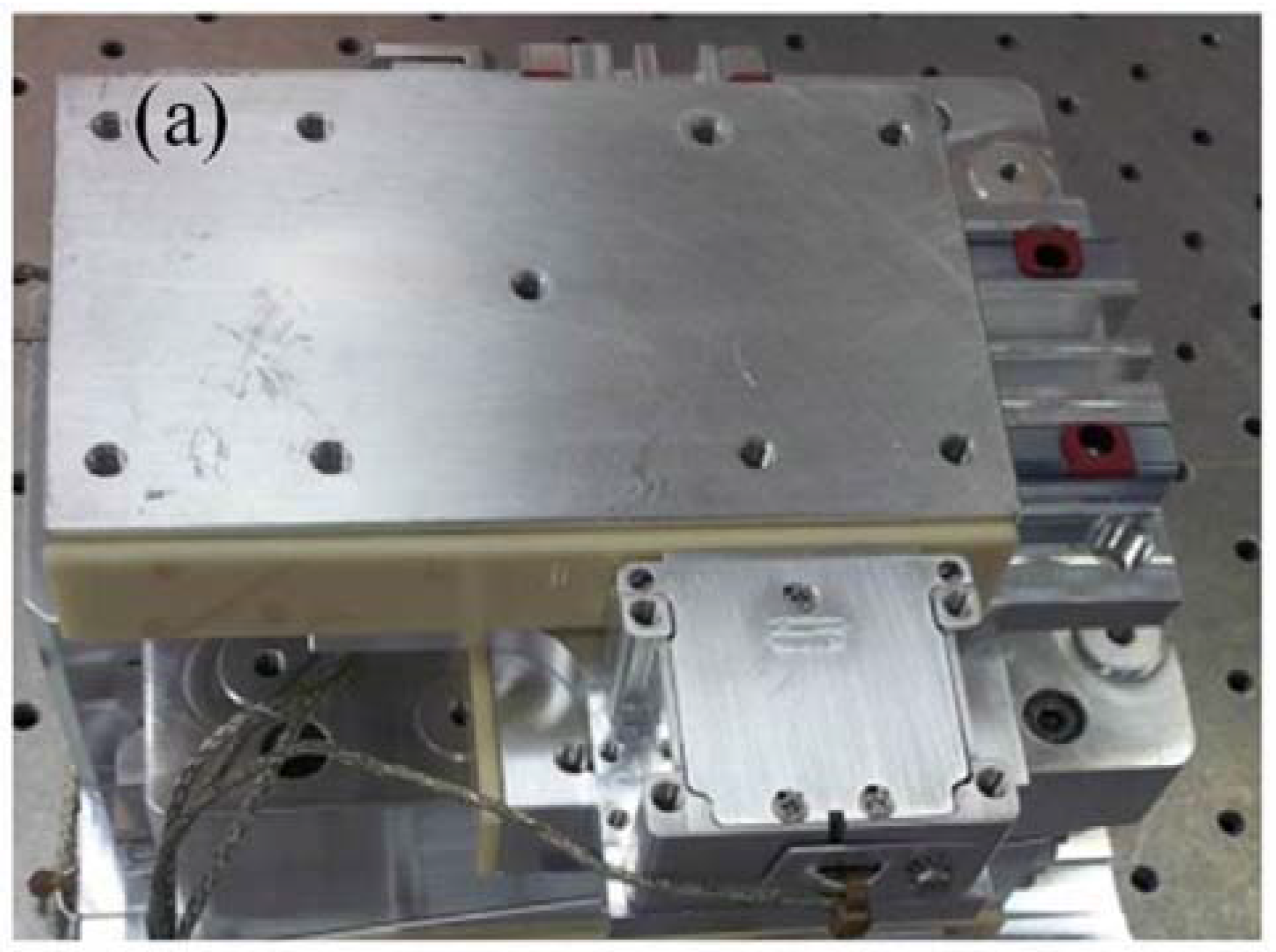
Figure 11.
Vacuum operation of a scanning stage: (a) Image of the setup including an HR2 vacuum motor and a linear stage having a moving mass of 230 g; (b) Motion profile during a single scanning cycle; (c) Position error rms, as function of the number of performed scanning cycles.
Figure 11.
Vacuum operation of a scanning stage: (a) Image of the setup including an HR2 vacuum motor and a linear stage having a moving mass of 230 g; (b) Motion profile during a single scanning cycle; (c) Position error rms, as function of the number of performed scanning cycles.

Figure 12.
Nanomotion FBR60-U rotary stage based on two HR2 vacuum motors: (a) Image of the stage without the encapsulating case; (b) Image of the stage with the encapsulating case; (c) Residual gas analysis analog scan of an FBR60-U high vacuum rotary stage idle in active vacuum (30 L vacuum chamber pumped via a turbomolecular vacuum pump). The scan was performed on an as cleaned stage, 60 h after the start of vacuum pumping.
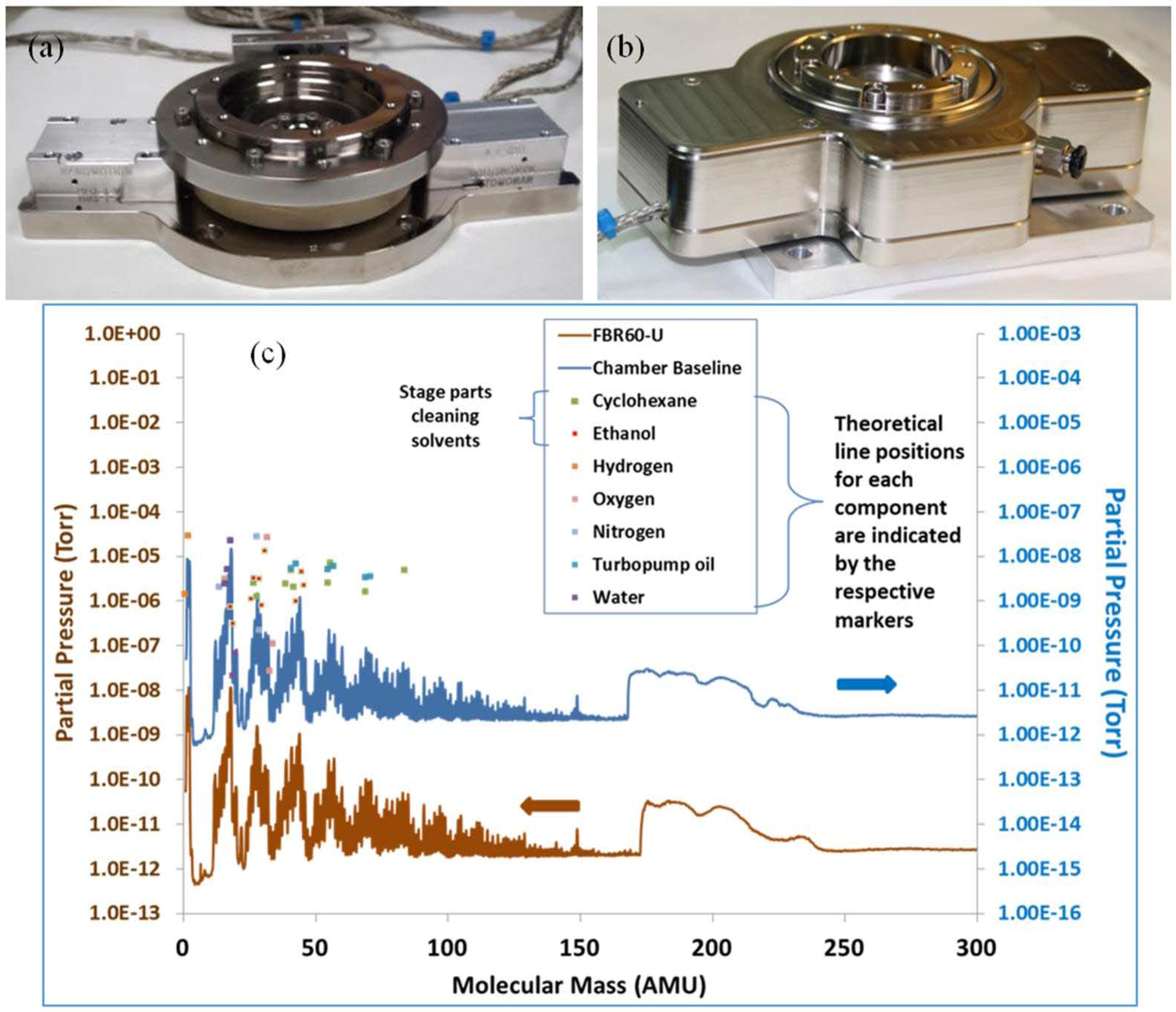
Figure 13.
The use of L1B2 motors for metrology and microscopy applications: (a) Four axis stage for ion beam etching; (b) three axis stage for wafer handling; (c) five axis stage for Nanolithography.
Figure 13.
The use of L1B2 motors for metrology and microscopy applications: (a) Four axis stage for ion beam etching; (b) three axis stage for wafer handling; (c) five axis stage for Nanolithography.
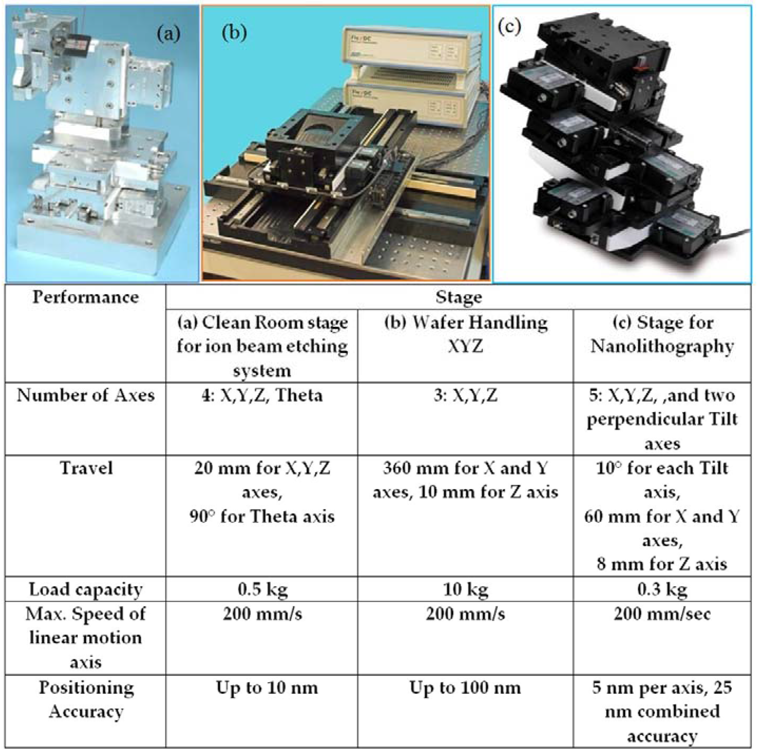
Figure 14.
Examples of L1B2 motor use in biomedical applications: (a,b) Two Nanomotion HR2-V motors are used to rotate a shaft in a tumor ablation instrument operating inside an MRI instrument having a magnetic field of 3 Tesla; (c) Schematic drawing of a rotary module designed to provide zoom capabilities for endoscopy tools; (d) An image of the module that is schematically shown in (c).

Figure 15.
Linear NUC shutter based on Nanomotion Edge L1B2 motor: (a) Schematic drawing of the Edge motor preloaded onto the drive strip; (b) Schematic drawing of the leaf motion mechanism; (c) Image of the linear NUC shutter.
Figure 15.
Linear NUC shutter based on Nanomotion Edge L1B2 motor: (a) Schematic drawing of the Edge motor preloaded onto the drive strip; (b) Schematic drawing of the leaf motion mechanism; (c) Image of the linear NUC shutter.
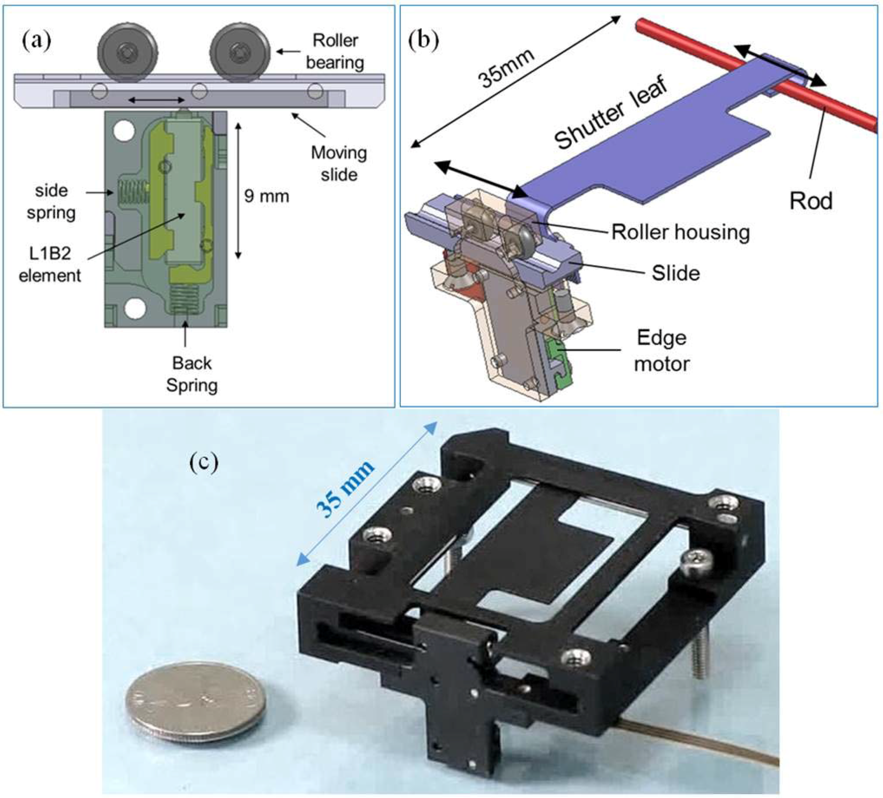
Figure 16.
(a) Image of a rotary NUC shutter based on a 9 mm long L1B2 element. The length of the unit is 20 mm; (b) An image of a shutter module with two rotary axes.
Figure 16.
(a) Image of a rotary NUC shutter based on a 9 mm long L1B2 element. The length of the unit is 20 mm; (b) An image of a shutter module with two rotary axes.


Table 1.
Example breakdown of a high vacuum compatible L1B2 motor (Nanomotion HR4-1-U-1.5 UHV) into material types by weight.
| Material/Part | Weight Percent of the Motor |
|---|---|
| Low outgassing metals | 49.57 |
| Plastic | 2.71 |
| Wiring (insulation + copper strands) | 18.14 |
| Adhesive | 0.06 |
| Elastomer | 0.08 |
| Ceramics | 29.44 |
© 2016 by the authors; licensee MDPI, Basel, Switzerland. This article is an open access article distributed under the terms and conditions of the Creative Commons Attribution (CC-BY) license (http://creativecommons.org/licenses/by/4.0/).
Share and Cite
MDPI and ACS Style
Peled, G.; Yasinov, R.; Karasikov, N. Performance and Applications of L1B2 Ultrasonic Motors. Actuators 2016, 5, 15. https://doi.org/10.3390/act5020015
AMA Style
Peled G, Yasinov R, Karasikov N. Performance and Applications of L1B2 Ultrasonic Motors. Actuators. 2016; 5(2):15. https://doi.org/10.3390/act5020015
Chicago/Turabian StylePeled, Gal, Roman Yasinov, and Nir Karasikov. 2016. "Performance and Applications of L1B2 Ultrasonic Motors" Actuators 5, no. 2: 15. https://doi.org/10.3390/act5020015
Note that from the first issue of 2016, this journal uses article numbers instead of page numbers. See further details here.