
Adaptive Piezoelectric Absorber for Active Vibration Control

Fraunhofer Institute for Structural Durability and System Reliability LBF, Bartningstr. 47, 64823 Darmstadt, Germany
*
Author to whom correspondence should be addressed.
Actuators 2016, 5(1), 7; https://doi.org/10.3390/act5010007
Submission received: 14 December 2015
/
Revised: 31 January 2016
/
Accepted: 15 February 2016
/
Published: 29 February 2016
(This article belongs to the Special Issue Piezoelectric Actuators)
Abstract
:Passive vibration control solutions are often limited to working reliably at one design point. Especially applied to lightweight structures, which tend to have unwanted vibration, active vibration control approaches can outperform passive solutions. To generate dynamic forces in a narrow frequency band, passive single-degree-of-freedom oscillators are frequently used as vibration absorbers and neutralizers. In order to respond to changes in system properties and/or the frequency of excitation forces, in this work, adaptive vibration compensation by a tunable piezoelectric vibration absorber is investigated. A special design containing piezoelectric stack actuators is used to cover a large tuning range for the natural frequency of the adaptive vibration absorber, while also the utilization as an active dynamic inertial mass actuator for active control concepts is possible, which can help to implement a broadband vibration control system. An analytical model is set up to derive general design rules for the system. An absorber prototype is set up and validated experimentally for both use cases of an adaptive vibration absorber and inertial mass actuator. Finally, the adaptive vibration control system is installed and tested with a basic truss structure in the laboratory, using both the possibility to adjust the properties of the absorber and active control.
1. Introduction
Tuned vibration absorbers (TVA) have been used since the beginning of the 20th century to reduce disturbing vibrations [1]. The original development aimed at damping of resonant vibrations with a damped absorber system. To cancel narrowband, forced vibrations, the TVA can be tuned to the excitation frequency, as well. In this case, the device is just lightly damped and often referred to as a vibration neutralizer in the literature [2]. To achieve sufficient performance over a wider bandwidth, the mass of the vibration neutralizer can be increased; alternatively, the vibration neutralizer can be designed to adapt its resonance frequency and to track the excitation frequency. Several basic concepts exist to adjust the resonance by actuation. Overviews can be found in [2,3,4]; also, some concepts will be introduced in the following section.
In previous studies, adaptive absorber concepts were evaluated regarding their performance, range of adaptation and reliability in fatigue tests [5]. It turned out that concepts that utilize piezoelectric actuation for the adaptation are more reliable compared to mechatronic solutions with servo motors due to less parts and no movable parts being used. Furthermore, the TVA can be dynamically excited above its resonance frequency and work as an inertial mass actuator [6], enhancing the bandwidth of the vibration reduction [7].
The work presented in this paper deals with investigations on a dynamic inertial mass actuator that has been developed previously [8] and which can also be used as an adaptive tuned vibration absorber. In the following section, the basic concepts for the adaptation of the resonance frequency are summarized and compared. The design of the adaptive absorber that will be investigated is introduced. Experiments on the performance of the different functions of the device are performed at a truss structure that was already used as an example for other laboratory experiments [8,9]. The structure can be considered a generic example of lightweight structures used in space applications or bridges. Similar experimental set ups have already been implemented and used for the evaluation of vibration control systems [10].
2. Adaptive Absorbers and Neutralizers
The general idea of a vibration neutralizer is to generate counteracting forces on a system that is excited by narrowband disturbing forces. A generic example for the system set up is shown in Figure 1.
The resulting frequency response function can be calculated using mechanical impedance formulations [9]. The admittance formulation for the neutralizer, which can be characterized by the mass m, resonance frequency and damping coefficient θ, reads:
With input admittance of the host structure , the admittance of the coupled subsystems results:
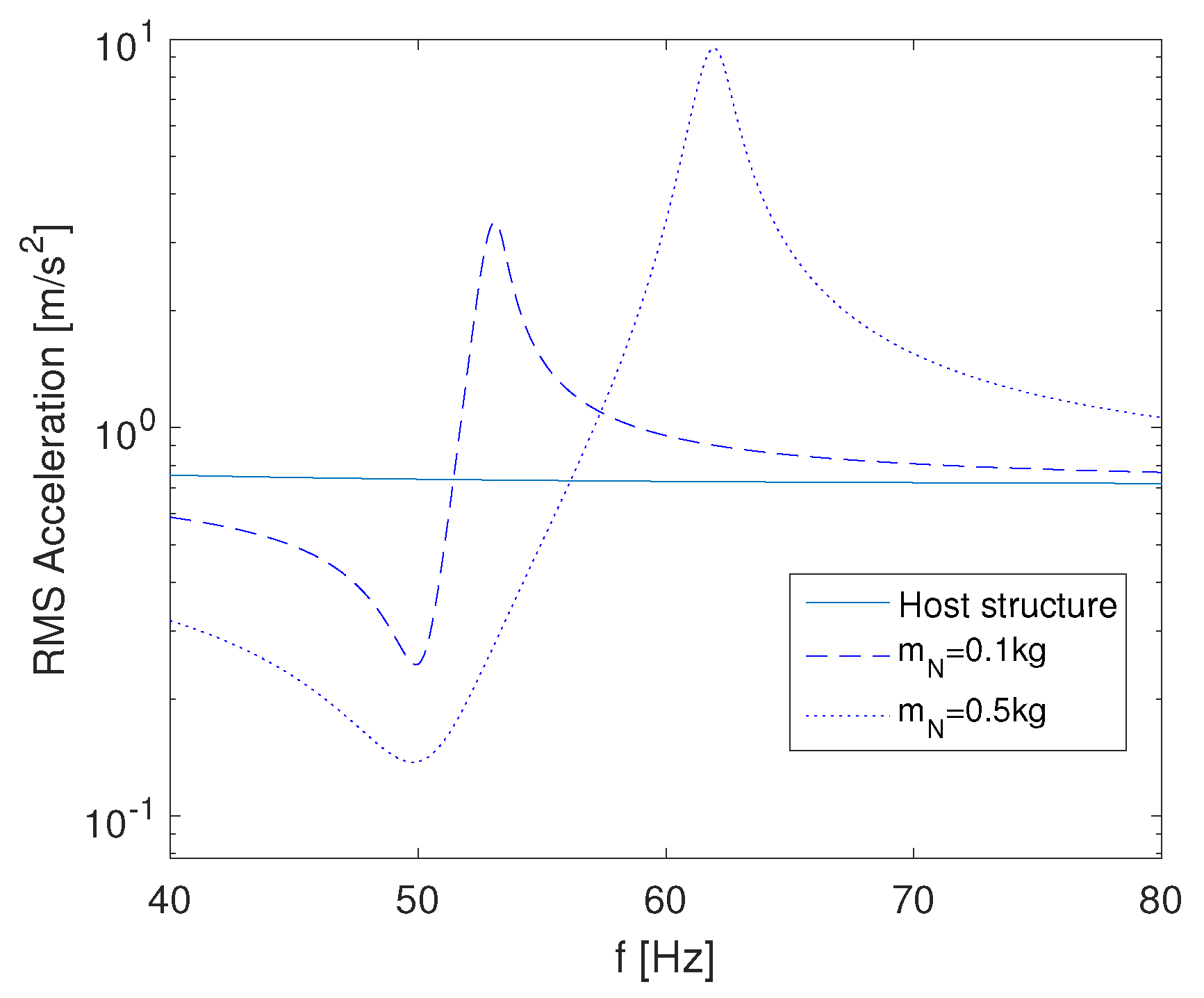
Obviously, the neutralizer causes two conjugate complex zeros in the resulting admittance, but also an additional pair of poles. A simple example with a mass of representing the host structure and an excitation force of illustrates the resulting admittance characteristics (Figure 2). For a neutralizer of tuned to , a significant drop in the vibration amplitude at the resonance is observed, but also a peak at about . If the excitation frequency were to increase above towards this frequency, the neutralizer would cause a deterioration of the vibrations. If a much larger neutralizer mass of is used, the bandwidth of vibration reduction is increased; however, in most practical problems, it is not possible to add another 50% to the host’s mass.
This motivates the integration of active elements to adjust the resonance frequency of the neutralizer. The bandwidth of the vibration reduction can be increased while still maintaining realistic mass ratios. Some basic concepts can be distinguished, here illustrated with the example of a simple vibration neutralizer based on a bending beam spring (Table 1).
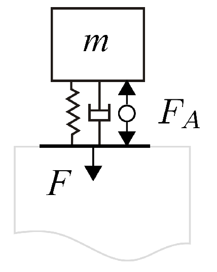
The first option is to induce a pre-stress into the beam in order to change its effective bending stiffness. This requires a static force that has to be steadily applied when the stiffness should be tuned. The most straightforward option is to adjust the geometry, e.g., the effective length of the beam, by moving the inertial mass. The advantage of this concept is that a variety of actuators is available for such a task. However, the movable parts in the system are prone to non-linearities and are sources of mechanical failures. The third way to be introduced here is the utilization of dynamic feedback. A dynamic feedback force (in the picture indicated by a piezo patch transducer on the bending beam) that is proportional to the acceleration of the inertial mass can adjust the effective mass of the absorber. Due to the dynamic feedback loop, this concept requires highly dynamic actuation systems. Furthermore, the feedback loop might have certain stability limits, which restrict the tuning range of the resonance frequency: in most elastic systems, more than a single vibration mode exists. For the acceleration feedback, the stability of the control loop is only guaranteed if the sensor and the actuator are collocated, which includes the minimum-phase behavior of the open loop [11]. However, for higher order modes of the bending beam, the sensor and actuator are not collocated any more, which limits the stability of the controlled system. Still, the main advantage of this concept is that the system can be used as an inertial mass actuator for active control of vibrations at the same time using a second control loop. The mechanical set up is identical to the adaptive absorber (Figure 3), but if the actuator is driven well above the resonance frequency of the system, the device can be considered a nearly ideal force generator. In this case, the generated force equals the actuator force (Figure 4), alleviating the task of control system design for the active control of vibrations.
With the transverse actuator force being , the block force of the inertial mass actuator reads:
Obviously, all concepts introduced possess specific benefits and drawbacks. In this work, an adaptive vibration absorber concept is investigated that can also be used as an inertial mass actuator. However, the resonance is adapted by using static pre-stress forces instead of dynamic actuation. This should enable a wide tuning range for the resonance frequency.
3. Design of the Adaptive Piezoelectric Absorber
The considerations are applied to design an adaptive vibration absorber with integrated piezoelectric transducers. A well-known design concept for vibration absorbers consists of a thin beam with a tip mass, which is used in this paper, as well. To activate the absorber, two piezoelectric stack transducers, working as actuators, are mounted in parallel to the beam (Figure 5).
The application of tensile normal force to the thin beam by the static elongation (in phase) of piezoelectric actuators enables the adaptation of the absorber’s natural frequency. Alternatively, the actuators can be used in dynamic operation (out of phase) to generate transverse forces. Adaptive behavior in this operation mode is obtained introducing a virtual change of the mass or the stiffness of the absorber by acceleration, respectively displacement, feedback control.
3.1. Basic Equations
The integration of the beam and the piezoelectric actuators is simplified in order to enable a modular, reconfigurable adaptive absorber system (Figure 5 and Figure 6). The two piezoelectric actuators are mounted at a certain distance to the neutral axis of the beam. The inertial mass is intended to serve also as a lever for the actuation.
Applying a static voltage to both actuators, a tensile (normal) force is induced at the beam, which is responsible for additional beam stiffness. In general, this effect can be described by the differential equation for the axially-loaded Euler-Bernoulli beam (4).
A solution of the aforementioned differential equation can be obtained by the trial function:
The coefficients can be found by solving a system of Equation (7) defined by the boundary conditions of the system:
This leads to:
In order to include the geometry of the mass, the distance from the end of the beam to the center of gravity of the mass is defined by a (refer to Figure 6). In Equation (8), the displacement is evaluated at this point.
Transforming Equation (8) according to the external transverse load F and dividing the equation by this force, the effective transverse stiffness at of the system depending on the normal force in the beam is derived.
For the investigation, generic piezoelectric actuators are assumed, which are described by their longitudinal stiffness and block force . Both actuators are coupled to the tip of the beam by a lever of length h with respect to the neutral axis of the beam. The beam itself is characterized by its length l, Young’s modulus E and the moment of inertia . Since the actuators are coupled mechanically by spherical end caps, only normal forces are assumed to be transmitted at the mounting points of the actuators. External loads F and M are considered in order to couple the beam to other sub-systems, e.g., the tip mass.
By driving both actuators out of phase, a moment is generated at the tip of the beam, which causes a movement of the mass and, in turn, a transverse reaction force at the mounting. This mode of operation is preferably used for dynamic applications.
Tuning of the actuator by mechanical pre-loading is discussed in [8]. There numerical and experimental results show a good correlation. The static pre-loading by the piezoelectric actuators (electrical pre-loading) is more suitable. It allows for a simple adjusting of the TVA’s resonance frequency during operation. A huge number of contributions discussing piezoelectric actuators have been published in the last decades ([12,13,14,15] and many more). A detailed simplification of the linearized piezoelectric equations for the one-dimensional case is derived, for example, in [16]. In this paper, the force generation of the one-dimensional actuator equation is of special interest:
The actuator force is defined by summarizing the mechanical and the electro-mechanical force. The parameters of the actuator are the Young’s modulus , the cross-section , the length l, the electro-mechanical constant and the number of layers . Mechanical displacement u and electrical voltage are responsible for generating the actuator force. If the displacement u is set to zero, the block force for the piezoelectric actuator can be derived (11).
However, if the actuators are elongating, driven by a voltage, the beam is pre-stressed. For this internal effect, the serial connection of both members defines the effective displacement of the actuator (12).
The effective stiffness of the system is therefore defined by the serial arrangement of the actuator stiffness and the beam stiffness (refer to Equation 12). In this case, the normal force of the beam is identical to the force generated by both actuators. Using this relation, the bending stiffness at can be expressed with respect to the actuator voltage. In Section 4, the analytical and experimental results are compared, and a good match is observed.
3.2. Mechanical Design of the Adaptive Absorber
A thin beam is clamped between two steel blocks, which form the mounting of the inertial mass actuator. The width of the beam is large compared to its length to prevent torsion. The hole pattern of the mounting is suited for a connection to a shaker or a heavy breadboard. On the other side of the beam, the inertial mass is attached. It consists of an equal number of steel blocks on each side of the beam, which can be changed easily for experiments. The mass can be moved on the beam via slotted holes, which is necessary for the assembling of the piezoelectric actuators. These are monolithic multilayer actuators by CeramTec with a base area of × and a length of . On both sides of the piezoelectric actuators, spherical ceramic caps are glued to reduce damaging shear forces. To ensure the force transmission of the actuators and to avoid loosening and, therefore, the non-linear behavior, the actuators have to be pre-loaded. This is done by screws in the two masses next to the beam with a distance of to the beam’s surface. The tips of the pre-loading screws are concave as counterparts of the actuator’s ceramic caps. There are corresponding holes at the mounting at the same distance from the beam. This prevents shifting of the piezoelectric actuators in operation.
4. Experimental Validation
4.1. Analysis of the Adaptive Absorber Characteristics
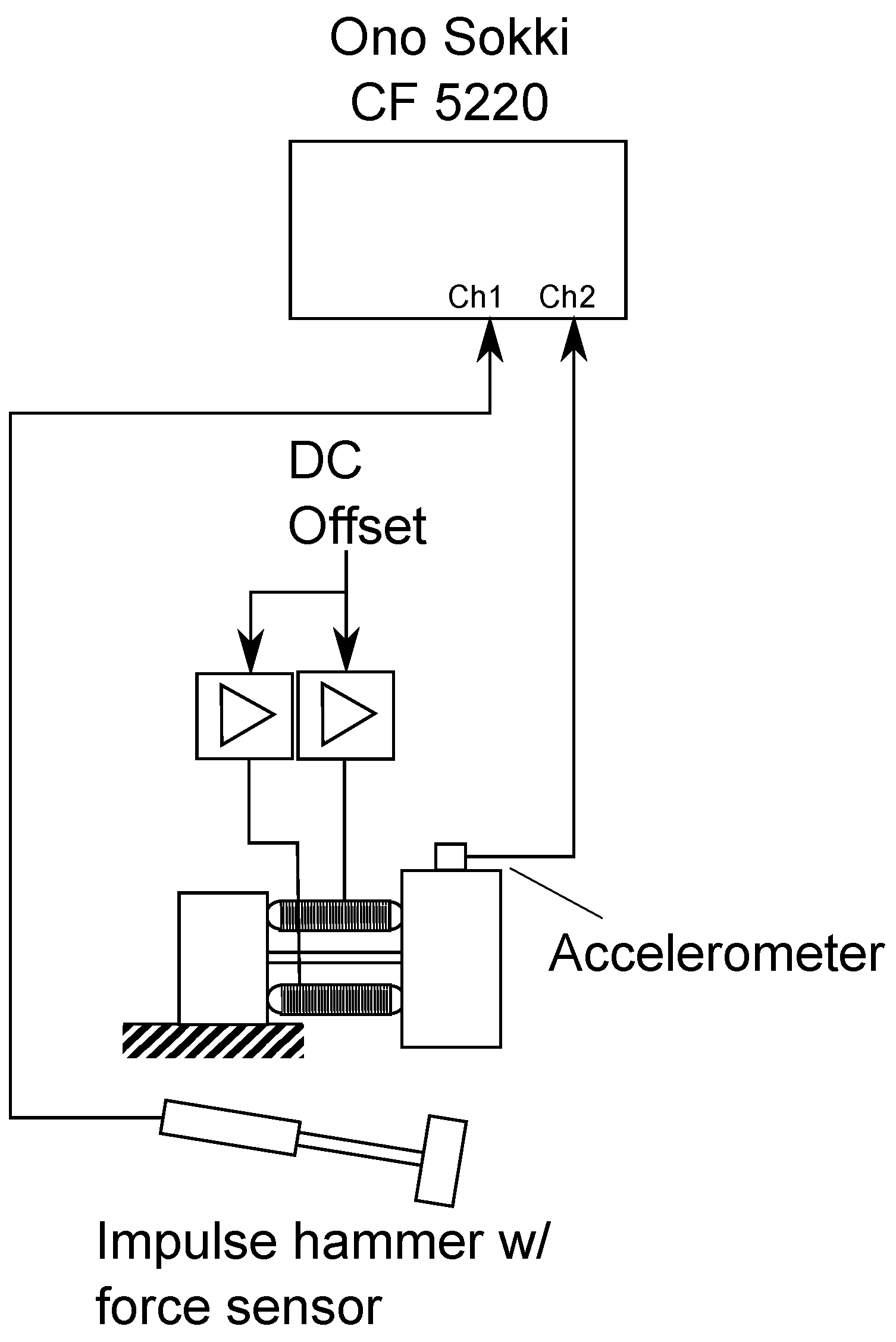
To analyze the dynamic characteristics of the adaptive absorber, tests were performed. The parameters for the actuator system are depicted in Table 2. The whole actuator was mounted to a rigid, heavy base plate, which can be treated as an infinitely small mechanical admittance in the considered frequency range (Figure 8). The tip mass was instrumented with an accelerometer. In order to estimate the resonance frequencies and analyze the tuning capabilities of the adaptive absorber, frequency response functions (FRF) were measured using a dynamic signal analyzer (Ono Sokki CF5220). The excitation force was applied with an impulse hammer, and the acceleration of the mass was measured with the attached sensor. A DC voltage was applied to both piezoelectric actuators by two amplifiers SVR 150 (Piezomechanik) to generate the pre-stress force, which tunes the vibration absorber. FRFs for different DC voltages between and were measured.
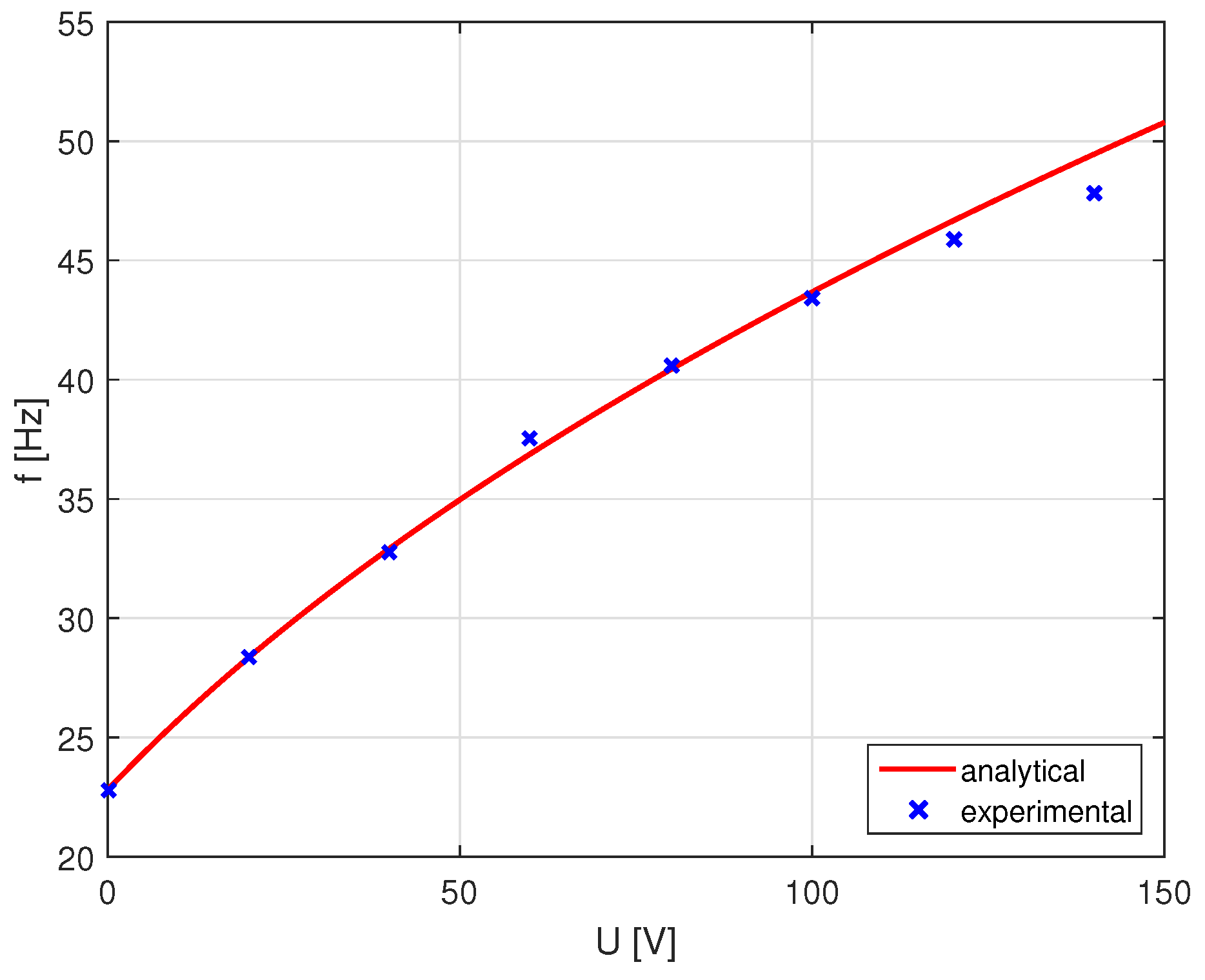
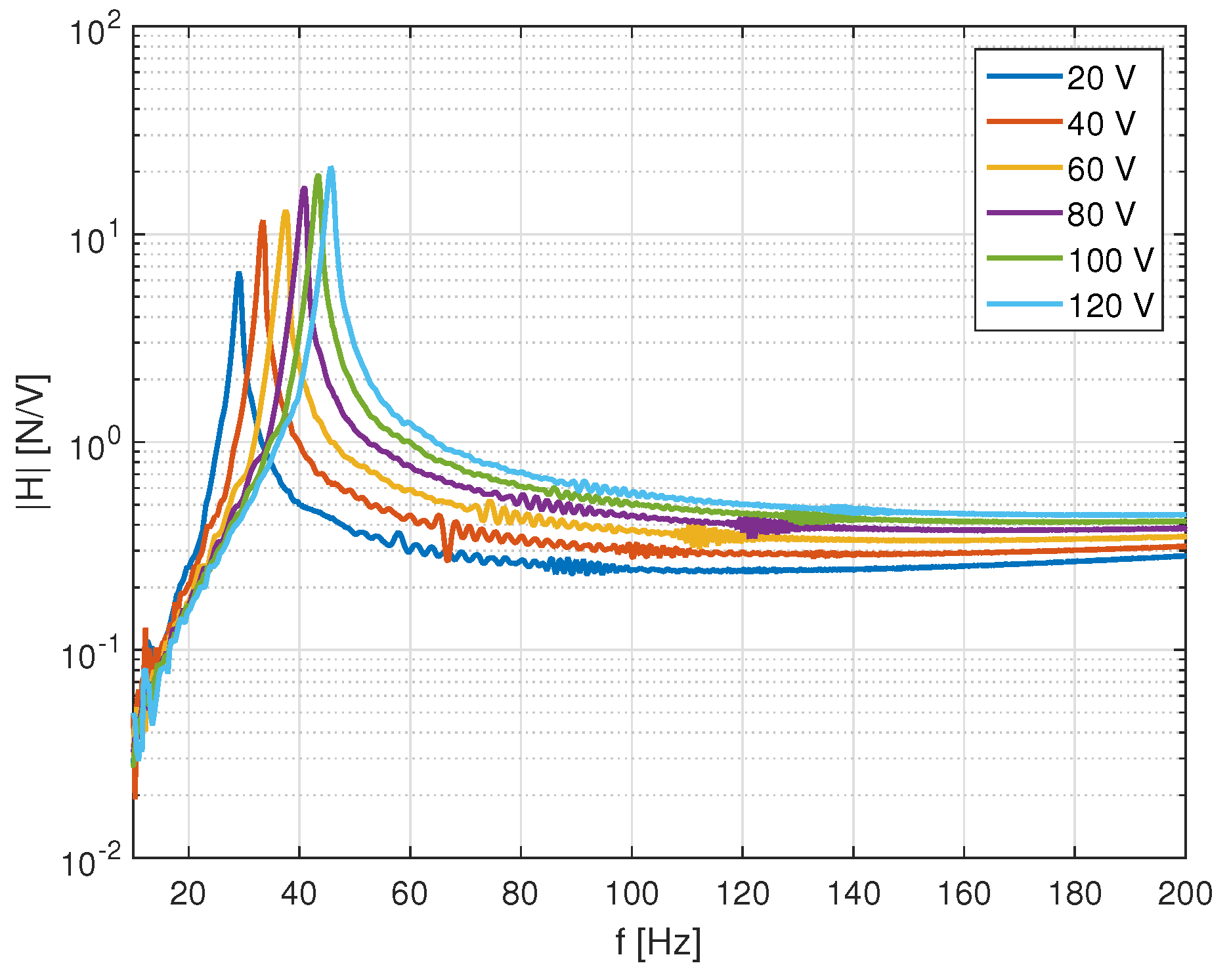
The resulting FRFs show the tuning capabilities of the system (Figure 9). Furthermore, the analytical model introduced in the preceding section is validated. The predicted FRFs by the model match well with the experimental results. Some differences can be observed for very low DC voltages, where the absorber does not exhibit perfect characteristics of an single-degree-of-freedom oscillator. This could be caused by a poor mechanical coupling between the piezo stacks and the structure when no pre-load is applied. For very high pre-loads around , the model predicts higher tuning effects than measured in the experiment (Figure 10). In this case, the analytical model might not perfectly predict the contact characteristics of the ball joints, which can be non-linear for high mechanical loads.
Overall, tuning between and was possible by DC pre-loads. This is equivalent to an adaptive absorber with a center frequency of and a tuning of . This performance is comparable to adaptive absorbers, which use motors for the variation of the spring geometry investigated in preliminary work [5].
4.2. Inertial Mass Actuator Performance
For the evaluation of the generated active force of the device, the piezoelectric actuators were driven with a swept sine signal generated by the analyzer. A simple analogue circuit generates an out of phase driving signal for one of the actuators in order to excite the bending mode of the actuator system, and the acceleration of the tip mass was measured (Figure 11). Since the mounting plate can be assumed not to interact with the active system, the block force can be directly derived from the acceleration and the mass.
For this test, different pre-loads from 20 to were applied to the actuators. The resulting FRFs between applied driving voltage and the generated force show the expected characteristics (Figure 12). In the frequency range above the first resonance and , no further resonances are excited. However, it was observed that the FRFs are influenced by the pre-load. The block force above the resonance increases slightly with the pre-loading voltage. This might be caused by a non-linearity in the piezoelectric elements, i.e., a dependency of the piezoelectric constant to the pre-load.
5. Application to an Active Vibration Control System
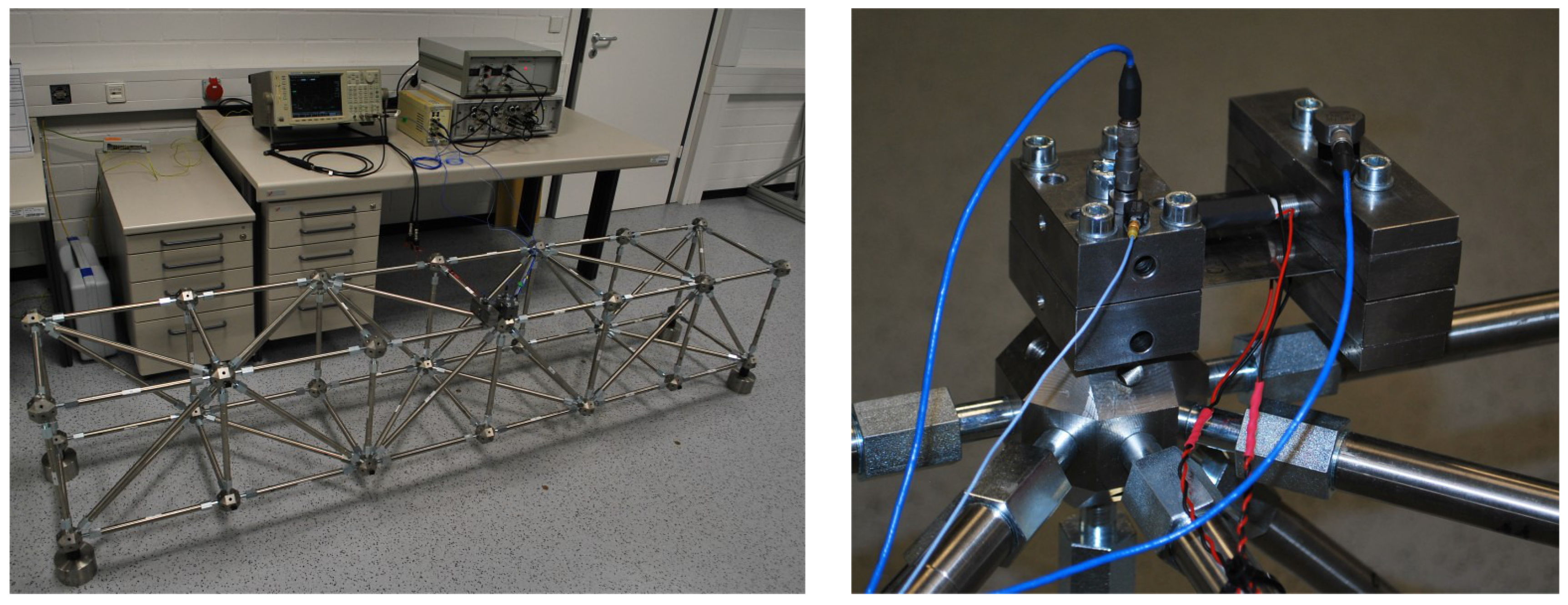
To evaluate the performance in an active vibration control system, the adaptive absorber was mounted to a lightweight truss structure (Figure 13). It was instrumented with accelerometers at its base and at the inertial mass.
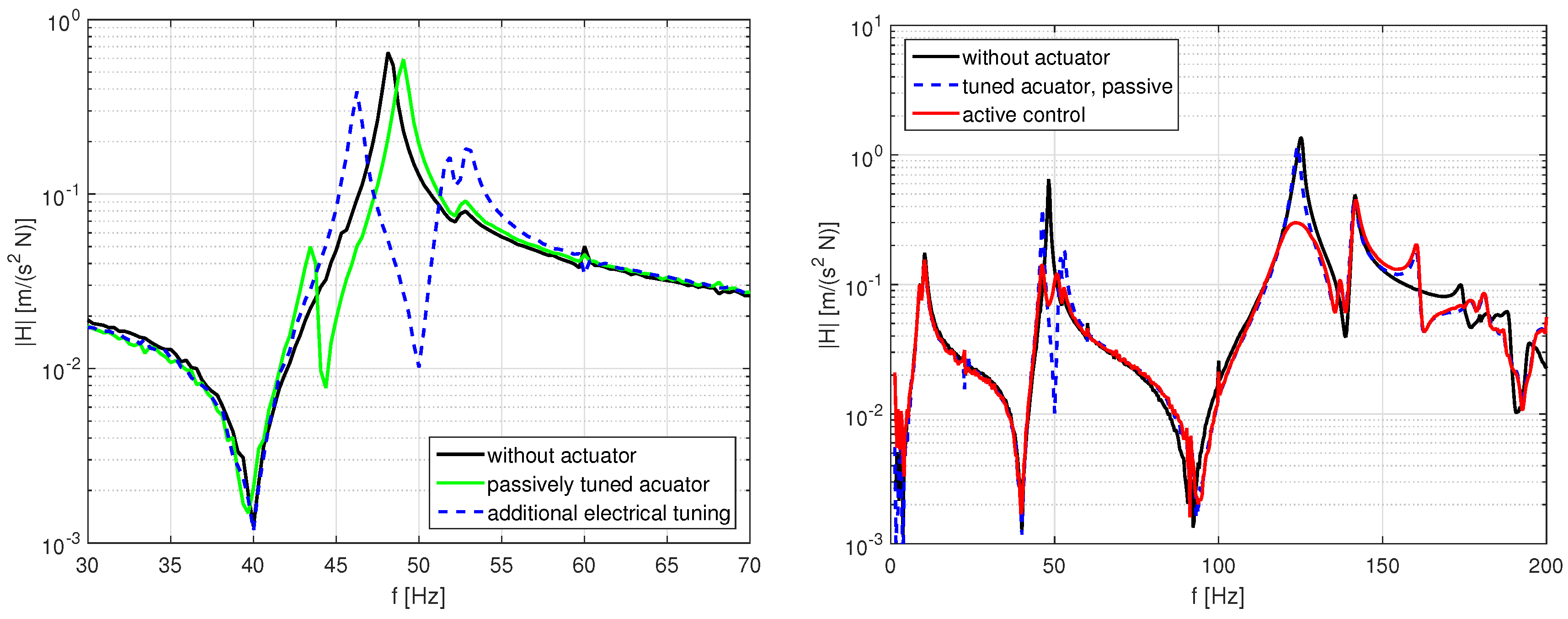
In the first step, the adaptive absorber was tuned by mechanical pre-load to a structural mode, which resulted in a vibration absorption effect at (Figure 14, left). This effect was enhanced by choosing an additional electrical pre-load of , which resulted in an absorption frequency of . Although this frequency does not match the structural resonance at exactly, this configuration served well as a basis for adjusting the active control system.
In the next step, the active control system was set up and tuned. Two control loops were implemented successively and connected (Figure 15). First, an active velocity feedback loop was used to enhance the damping of the inertial mass actuator, which caused the better performance of the absorption at the first mode at 48 Hz and a higher robustness against the interaction between different control loops. In order to derive the dynamic velocity from the measured acceleration at the tip mass, an integrator is used. In a practical control system, this is implemented with a low pass filter:
The cut-off frequency is set well below the resonance of the actuator, here at about 5 Hz, and is chosen appropriately.
Second, an acceleration feedback loop was tuned to the second mode of the truss at 125 Hz (Figure 14, right). The corresponding transfer function is a second order low pass filter:
Here, is the tuning frequency and θ the damping coefficient, while is the control loop gain. The control system was implemented with analogue circuitry.
Since the actuator is not symmetric, a bending moment is exciting at its base additional to the normal force. This results in lowering of a higher resonance frequency from 180 Hz to 160 Hz and a deterioration of the vibration amplitudes there.
6. Results and Discussion
A piezoelectric adaptive vibration absorber was introduced that combines the possibility to tune the resonance frequency by static pre-stress forces with the option to generate dynamic signals, which can be used for tuning of the absorber’s damping, but also for active vibration control in the frequency range above the resonance frequency. The properties were first evaluated by an analytical model and validated by experimental results. A good match between the predictions by the model and the measurements was observed. Furthermore, a relatively wide tuning range for the absorber’s resonance frequency was gained, which is comparable to other concepts using servo motors for tuning [5].
Furthermore, measurements of the generated dynamic force for the utilization as an inertial mass actuator were conducted. While generally, the block force was nearly constant above the resonance frequency, a slight dependency on the applied pre-loading voltage was observed. The vibration control experiments on a laboratory structure demonstrated the versatility of the concept. Tuning was possible using mechanically- and electrically-applied pre-loads. The damping could be adjusted by a velocity feedback loop, which is an interesting alternative to the commonly-used rubber elements in other absorber designs. Furthermore, the possibility for enhancement of the vibration control performance by using the device as an inertial mass actuator was successfully shown.
7. Conclusions
The results have shown that the design presented in this paper possesses the potential for vibration control applications. Generally, a wide tuning range of the adaptive absorber combined with the option to actively influence the absorber characteristics or to implement active control systems make this design an interesting alternative to other concepts.
However, there are also some existing design issues, which limit the performance. A certain level of pre-stress force should be applied in order to keep the properties of a single-degree-of-freedom oscillator, which limits the tuning range of the concept. Furthermore, the dual use as adaptive-passive and active device might be restricted: as the pre-loading voltage reaches the positive or negative maximum values of the used power amplifier, the maximum amplitude of the dynamic actuation should be decreased in order to avoid clipping effects. Furthermore, the dependency of the block force to the pre-load voltage should be considered when designing the active control loop; either adaptive control concepts like the filtered-X-LMS [17], parametric change of the gain with respect to the DC voltage or a design with a certain robustness to gain variations could be used.
Furthermore, further investigations and improvements of the adaptive absorber are necessary in order to enable the application outside the laboratory. The performance of the absorber in case of larger vibration amplitudes of the host structure should be analyzed; the reliability tests already performed with other types of adaptive absorbers should also be conducted with the design introduced in this paper. Finally, the mechanical design could be further improved towards a more compact solution.
Acknowledgments
This work was partly conducted within the framework of the LOEWE center AdRIA. The support by the state of Hesse is gratefully acknowledged. Furthermore, the support by our colleague Tobias Röglin, who conducted the general design of the adaptive absorber, is kindly acknowledged.
Author Contributions
D. Mayer conceived the vibration absorber. S. Herold derived the analytical models. D. Mayer and S. Herold performed the experiments, analyzed the data, and wrote the paper.
Conflicts of Interest
The authors declare no conflict of interest.
References
- Frahm, H. Device for damping vibrations of bodies. US Patent 989,958, 18 April 1911. [Google Scholar]
- Brennan, M.J. Some Recent Developments in Adaptive Tuned Vibration Absorbers/Neutralisers. Shock Vib. 2006, 13, 531–543. [Google Scholar] [CrossRef]
- Wright, R.I.; Kidner, M.R.F. Vibration Absorbers: A Review of Applications in Interior Noise Control of Propeller Aircraft. J. Vib. Control 2004, 10, 1221–1237. [Google Scholar] [CrossRef]
- Bonello, P. Adaptive Tuned Vibration Absorbers: Design Principles, Concepts and Physical Implementation. In Vibration Analysis and Control - New Trends and Developments; Beltran-Carbajal, F., Ed.; InTech: Rijeka, Croatia, 2011. [Google Scholar]
- Mayer, D.; Pfeiffer, T.; Vrbata, J.; Melz, T. Adaptive-passive vibration control systems for industrial applications. Proc. SPIE 2015, 9433. [Google Scholar] [CrossRef]
- Winberg, M.; Johansson, S.; Claesson, I. Inertial mass actuators, understanding and tuning. In Proceedings of the ICSV 11, St. Petersburg, Russia, 5–8 July 2004.
- Konstanzer, P.; Grünewald, M.; Jänker, P.; Storm, S. Piezo Tuneable Vibration Absorber System for Aircraft Interior Noise Reduction. In Proceedings of the Euronoise 2006, Tampere, Finland, 30 May–1 June 2006.
- Herold, S.; Mayer, D.; Melz, T.; Röglin, T. Design and Test of a Piezoelectric Inertial Mass Actuator for Active Vibration Control. In Vibration Engineering and Technology of Machinery; Sinha, J., Ed.; Mechanisms and Machine Science, Springer International Publishing: Cham, Switzerland, 2014; Volume 23, pp. 587–597. [Google Scholar]
- Mayer, D.; Kauba, M.; Herold, S.; Koch, T. Approaches for distributed active and passive vibration compensation. In Proceedings of the ISMA 2010, 24th International Conference on Noise and Vibration Engineering, Leuven, Belgium, 20–22 September 2010; p. 13.
- Hagood, N.W.; Crawley, E.F. Experimental investigation into passive damping enhancement for space structures. J. Guidance Control Dyn. 1991, 14, 1100–1109. [Google Scholar] [CrossRef]
- Preumont, A. Vibration Control of Active Structures; Springer: Dordrecht, Netherlands, 2011. [Google Scholar]
- Crawley, E.F.; Luis, J.D. Use of piezoelectric actuators as elements of intelligent structures. AIAA J. 1987, 25, 1373–1385. [Google Scholar] [CrossRef]
- Benjeddou, A. Advances in piezoelectric finite element modeling of adaptive structural elements: A survey. Comput. Struct. 2000, 76, 347–363. [Google Scholar] [CrossRef]
- Ruschmeyer, K. Piezokeramik: Grundlagen, Werkstoffe, Applikationen; Expert-Verl.: Renningen-Malmsheim, Germany, 1995. [Google Scholar]
- Herold, S.; Mayer, D.; Hanselka, H. Transient Simulation of Adaptive Structures. J. Intell. Mater. Syst. Struct. 2004, 15, 215–224. [Google Scholar] [CrossRef]
- Herold, S.; Atzrodt, H.; Mayer, D.; Thomaier, M. Modeling approaches for active systems. Proc. SPIE 2006, 6173. [Google Scholar] [CrossRef]
- Elliott, S. Signal Processing for Active Control; Academic Press: Cambridge, MA, USA, 2000. [Google Scholar]
Figure 1.
Generic example for a system with a vibration neutralizer.

Figure 2.
Vibration amplitude for a structure without and with neutralizers of different masses.

Figure 3.
Principle of an inertial mass actuator.

Figure 4.
Frequency response function of an inertial mass actuator ().
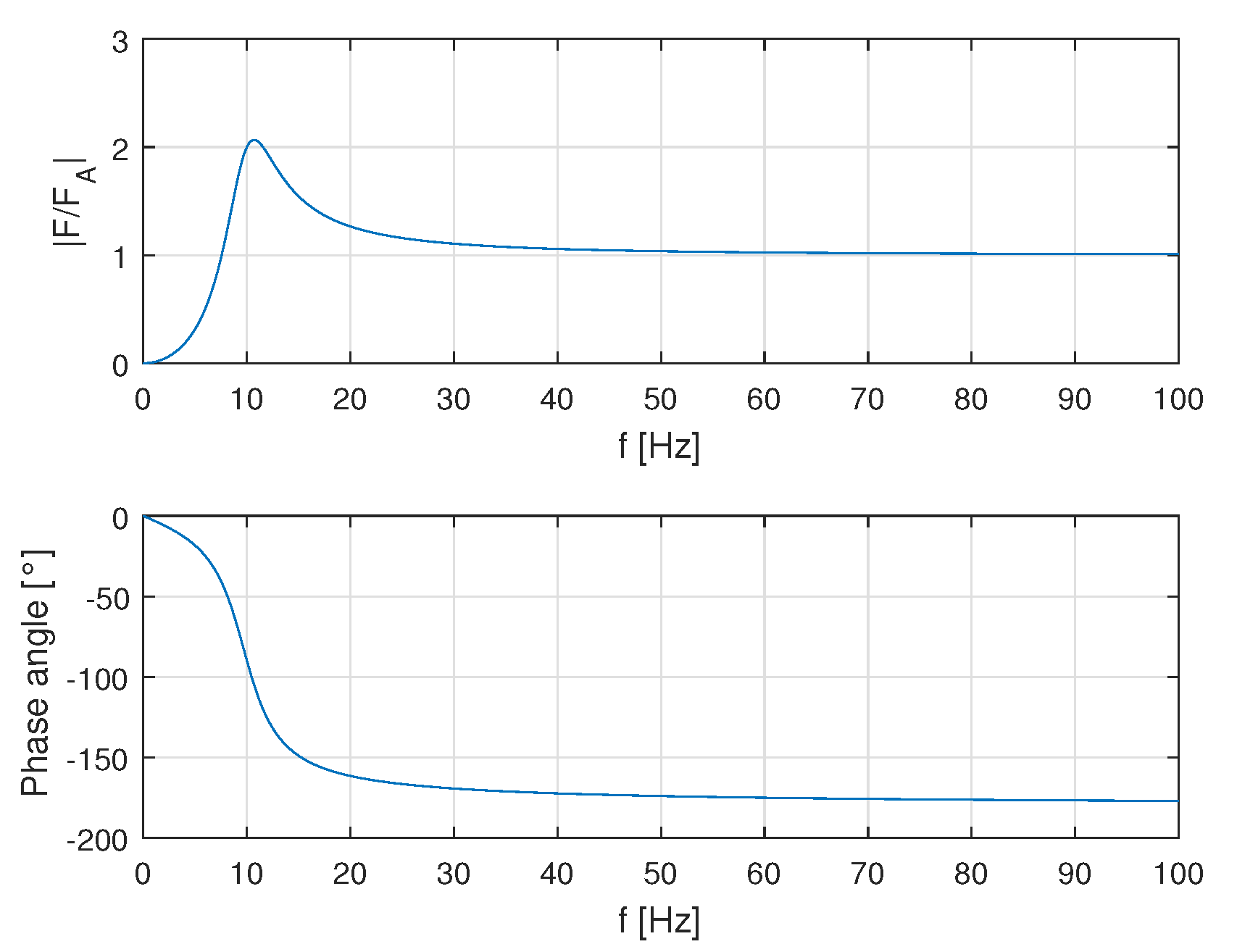
Figure 5.
Basic design of the adaptive vibration absorber.
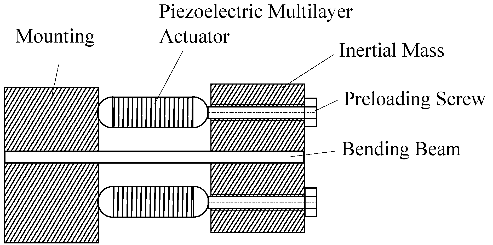
Figure 6.
Mechanical sketch of the adaptive vibration absorber.
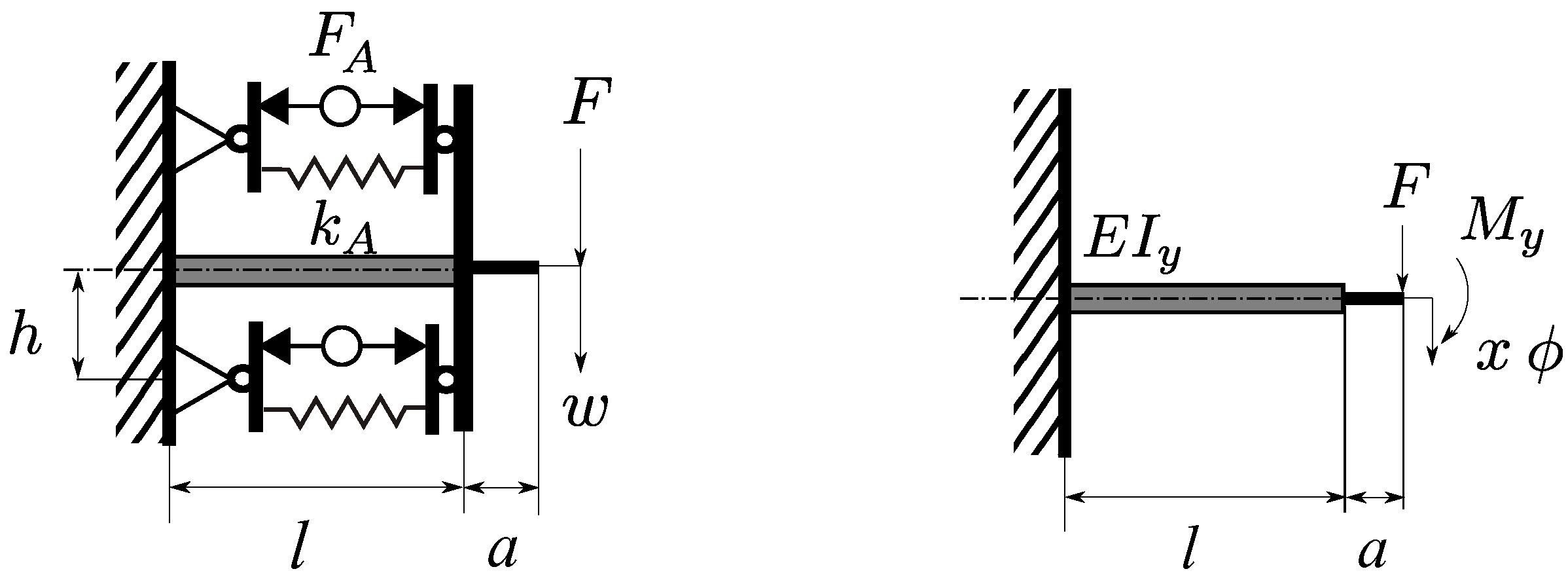
Figure 7.
Implemented prototype of the adaptive vibration absorber.
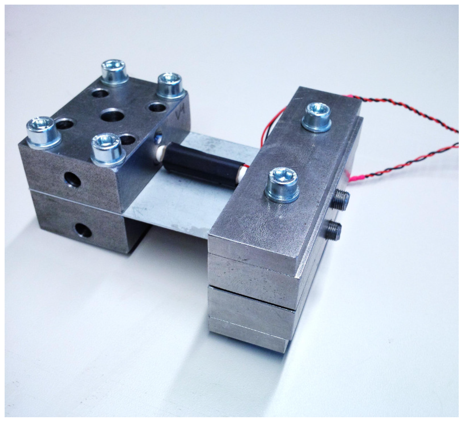
Figure 8.
Test set up for the dynamic analysis of the adaptive vibration absorber.

Figure 9.
Frequency response functions of the adaptive vibration absorber for different DC voltages.
Figure 9.
Frequency response functions of the adaptive vibration absorber for different DC voltages.
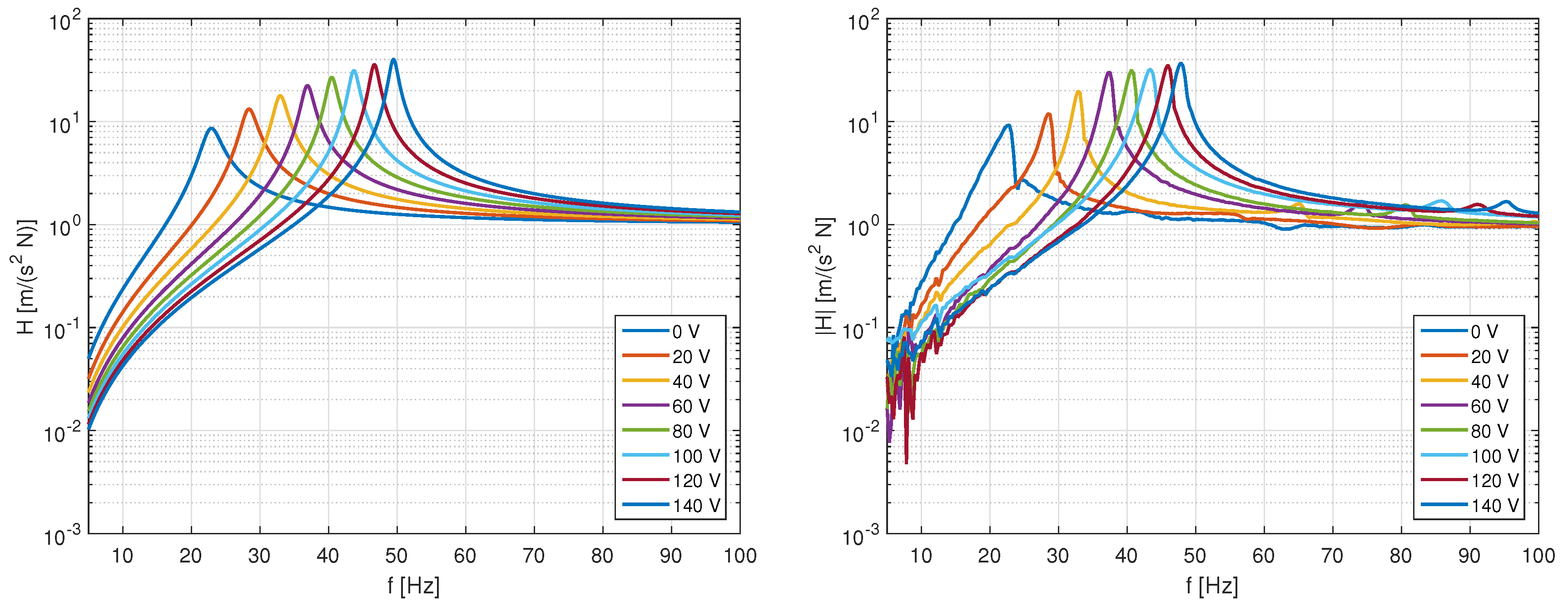
Figure 10.
Comparison of resonance frequencies (analytical and experimental) for the electrical tuning of the adaptive vibration absorber.
Figure 10.
Comparison of resonance frequencies (analytical and experimental) for the electrical tuning of the adaptive vibration absorber.

Figure 11.
Test set up for the measurement of the dynamic block force of the actuator.
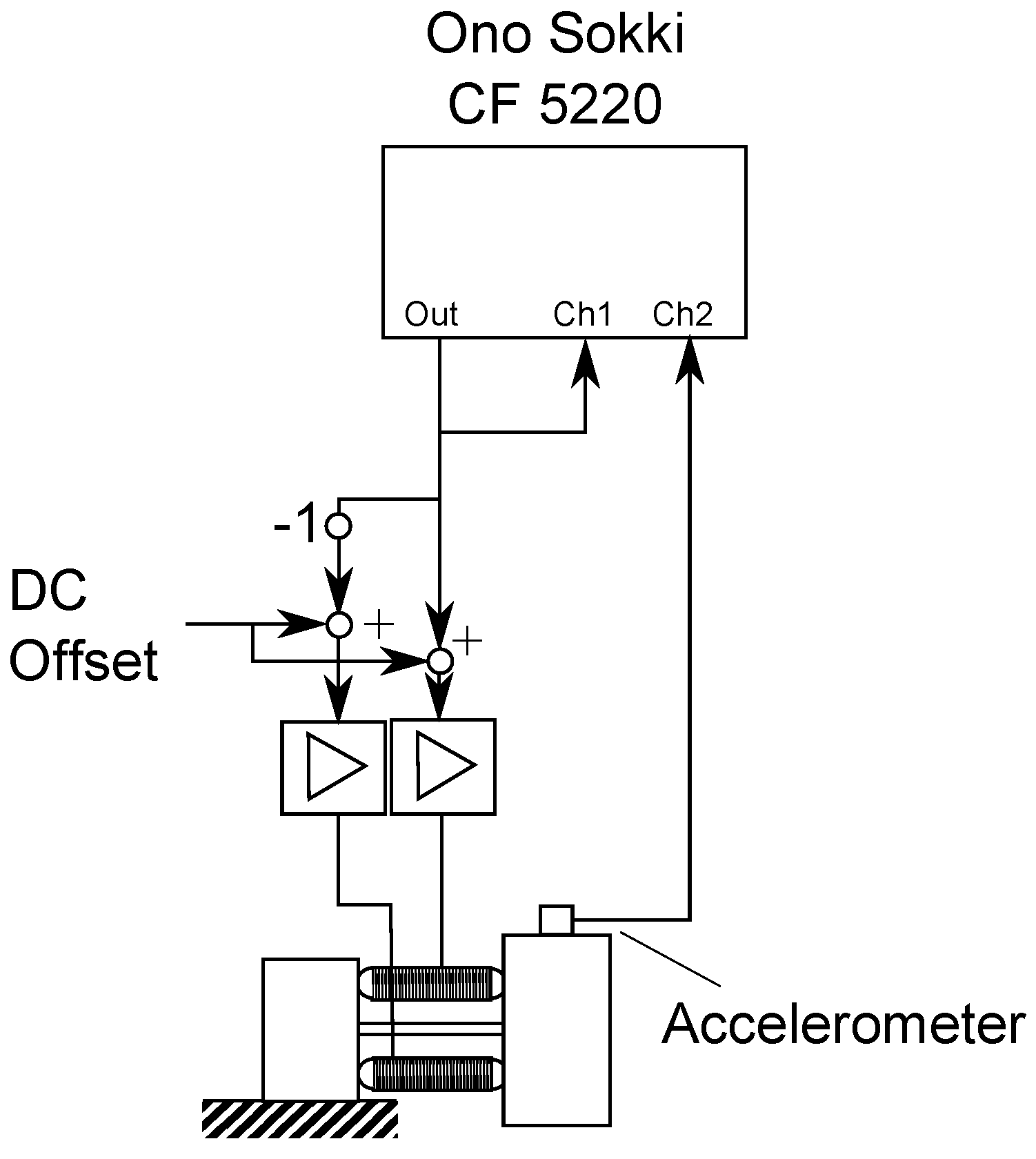
Figure 12.
Measurement of the dynamic block force of the actuator.

Figure 13.
Test set up for the active control experiment (left) and detail of the actuator instrumentation (right).
Figure 13.
Test set up for the active control experiment (left) and detail of the actuator instrumentation (right).

Figure 14.
Tuning of the adaptive absorber to the first elastic mode of the truss and control results.
Figure 14.
Tuning of the adaptive absorber to the first elastic mode of the truss and control results.

Figure 15.
Block diagram of the control system.


Table 1.
Different adaptation concepts for neutralizers [5].
| Concept | Static Pre-Stress | Variable Geometry | Dynamic Forces |
|---|---|---|---|
 |  |  |  |
| Actuator type | Static, high force | Static, high stroke | Dynamic force |
| Examples | Piezoelectric | Motor, shape memory alloys | Piezoelectric, electrodynamic |
| Energy Supply | Continuously | During adaptation | Continuously |
| Quantity | Symbol | Value | Unit |
|---|---|---|---|
| beam | |||
| length | l | ||
| width | b | 60 | |
| thickness | d | ||
| Young’s modulus | E | ||
| mass | |||
| mass | m | ||
| actuator | |||
| stiffness | |||
| max. block force | 2000 | ||
© 2016 by the authors; licensee MDPI, Basel, Switzerland. This article is an open access article distributed under the terms and conditions of the Creative Commons by Attribution (CC-BY) license (http://creativecommons.org/licenses/by/4.0/).
Share and Cite
MDPI and ACS Style
Herold, S.; Mayer, D. Adaptive Piezoelectric Absorber for Active Vibration Control. Actuators 2016, 5, 7. https://doi.org/10.3390/act5010007
AMA Style
Herold S, Mayer D. Adaptive Piezoelectric Absorber for Active Vibration Control. Actuators. 2016; 5(1):7. https://doi.org/10.3390/act5010007
Chicago/Turabian StyleHerold, Sven, and Dirk Mayer. 2016. "Adaptive Piezoelectric Absorber for Active Vibration Control" Actuators 5, no. 1: 7. https://doi.org/10.3390/act5010007
Note that from the first issue of 2016, this journal uses article numbers instead of page numbers. See further details here.