Realization of an Automated Vertical Warp Stop Motion Positioning


Abstract
:1. Introduction

2. State of the Art
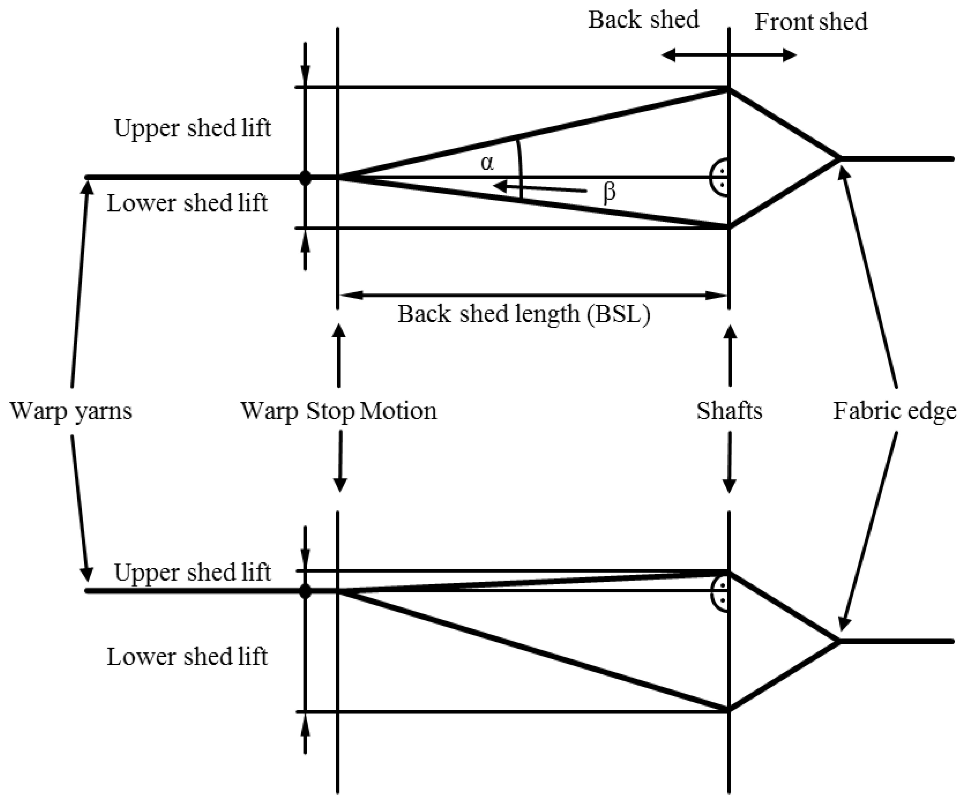
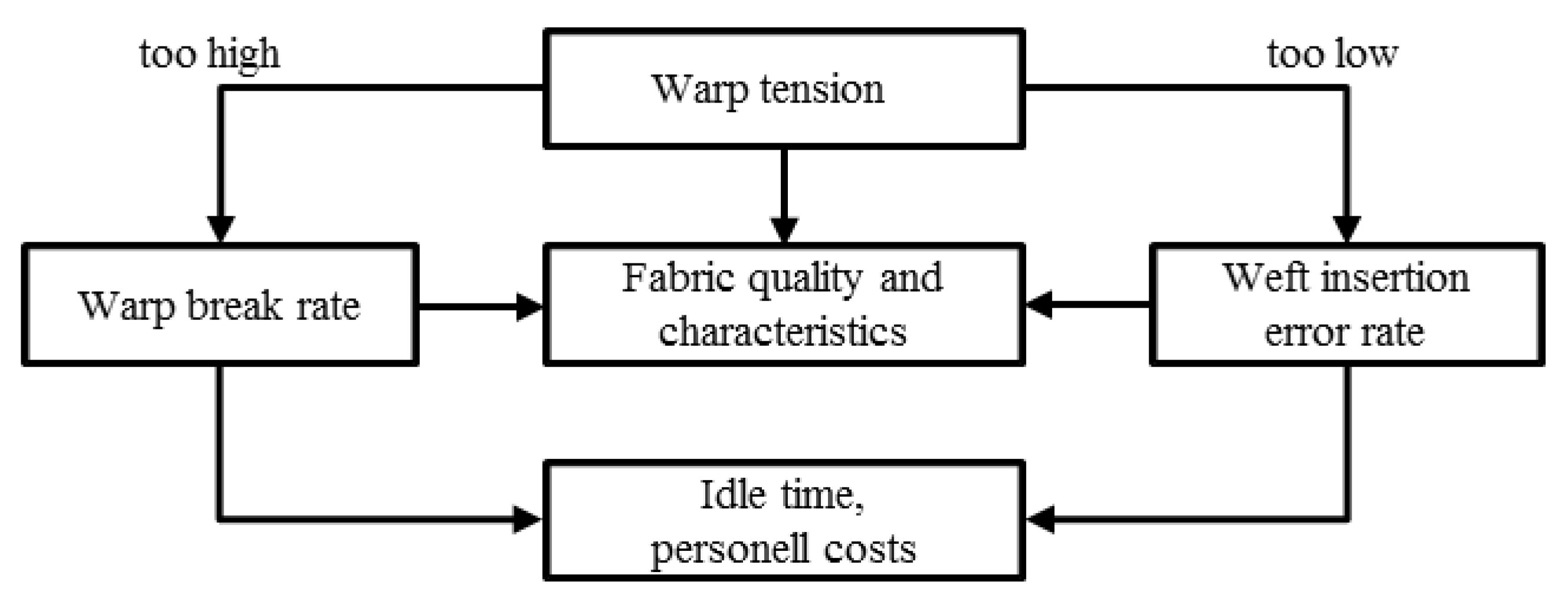
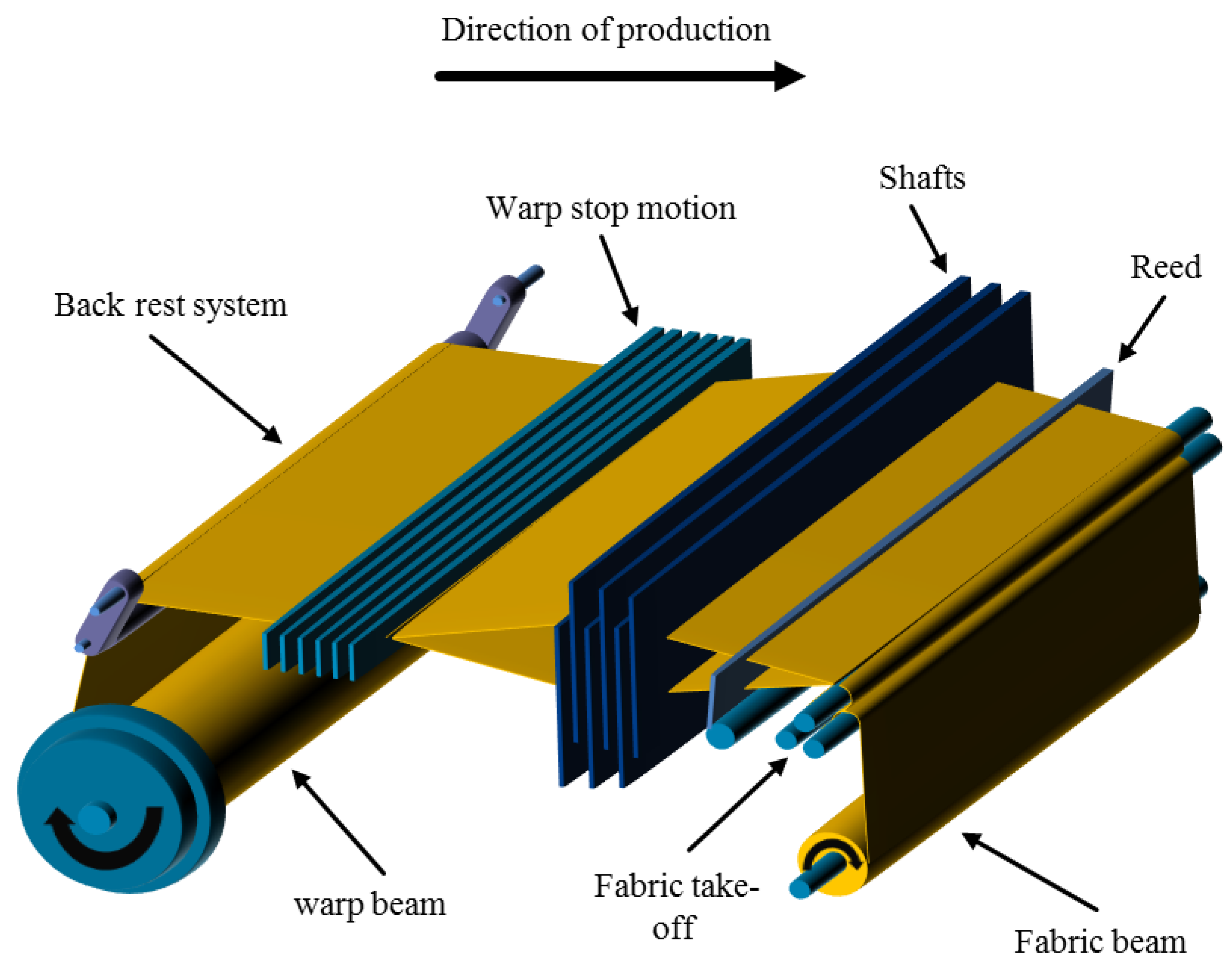
2.1. Importance of the Warp Stop Motion Position
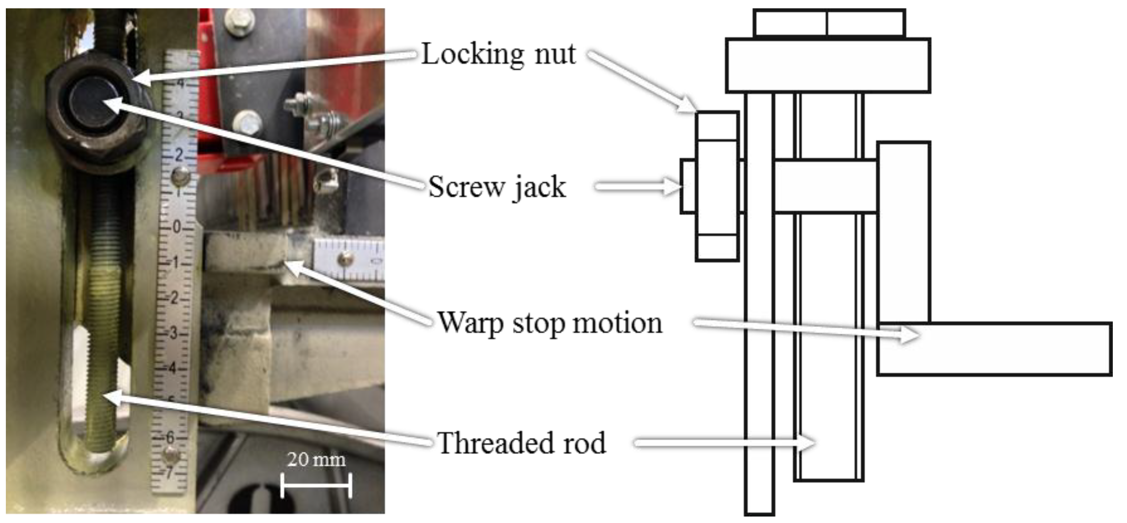
2.2. Setting of the Warp Stop Motion Position
2.3. Motivation
3. Concept for the Vertical Warp Stop Motion Variation
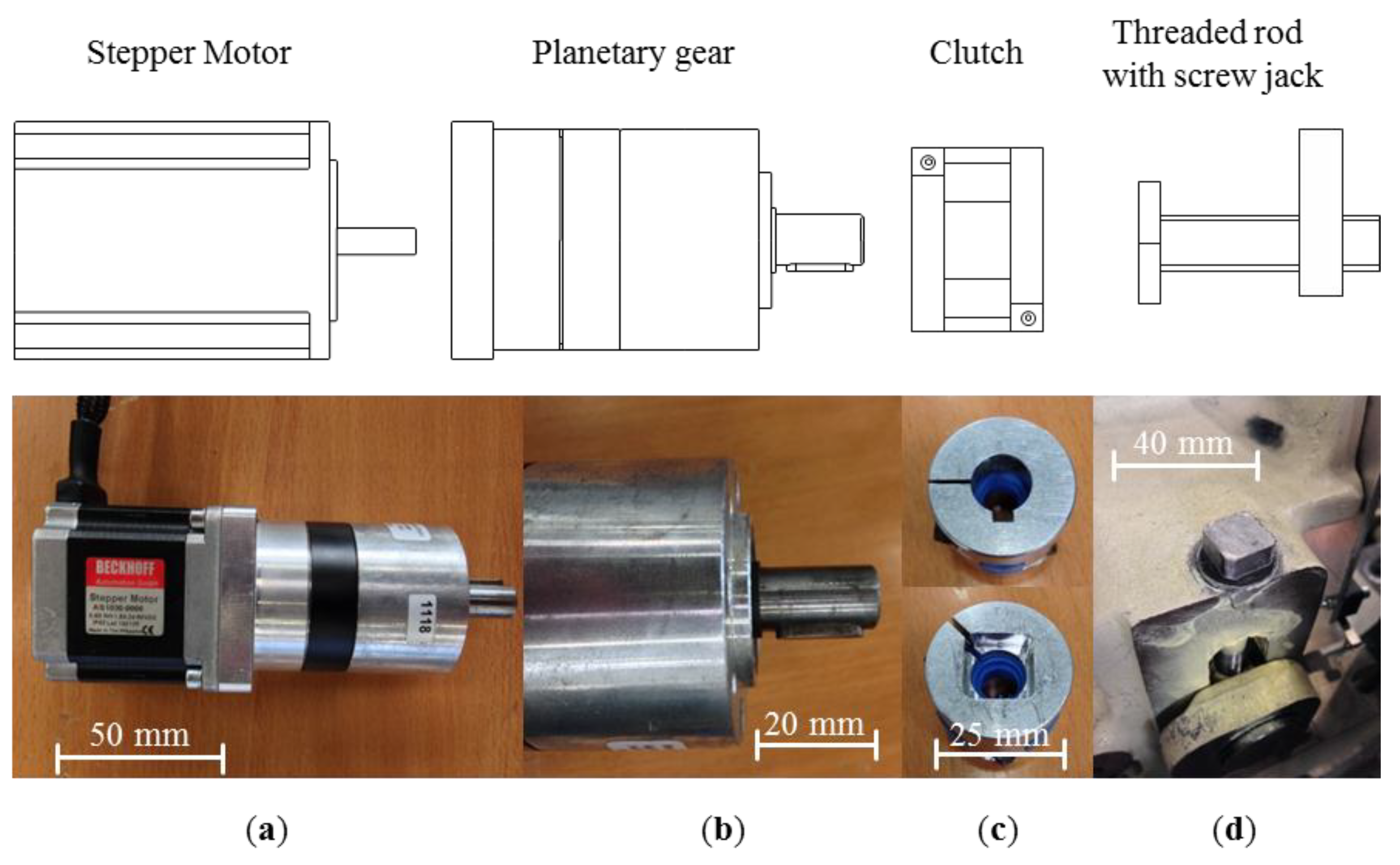
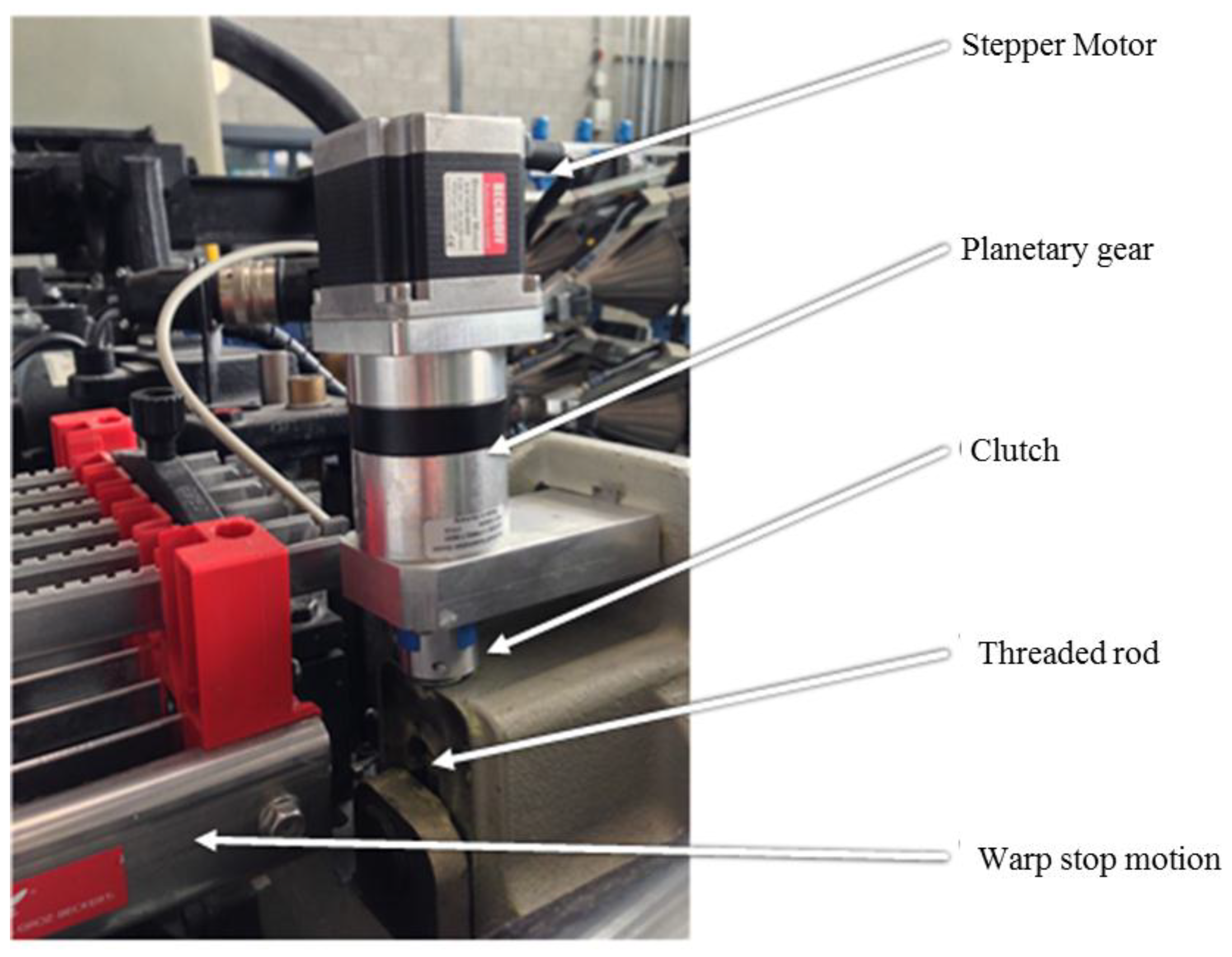
3.1. Drive and Transmission
- Motor
- Planetary gear
- Clutch


| Model | AS1030-0000 |
|---|---|
| Rated supply voltage | 24–50 V DC |
| Rated current (per phase) | 1.5 A |
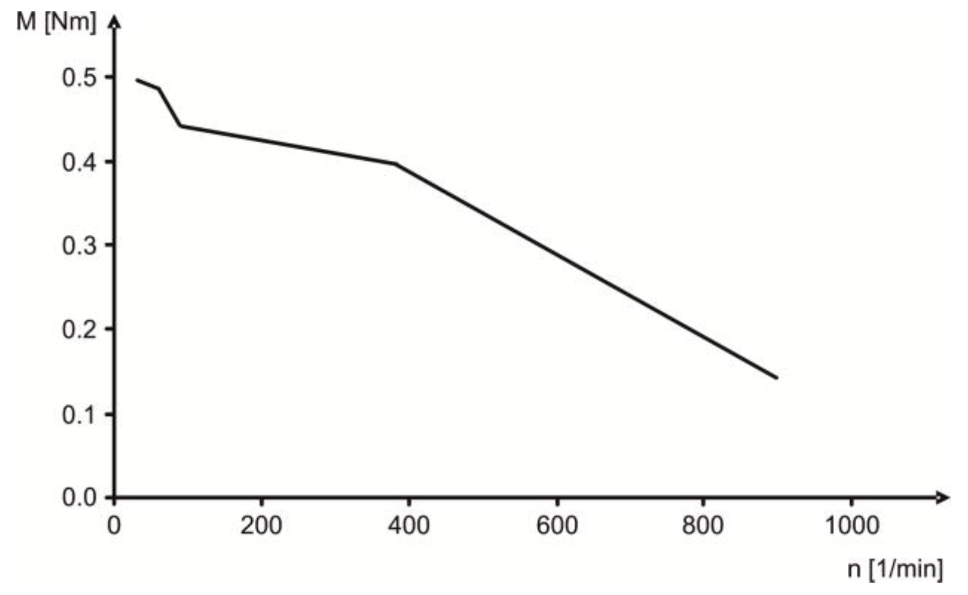
| Standstill torque | 0.6 Nm |
| Winding resistance (per phase) | 0.8 Ω |
| Winding inductance (per phase) | 3.8 mH |
| Rotor moment of inertia | 0.21 kg·cm2 |
| Dimensions (radius × length) | 56 mm × 53 mm |
| Resolution | 1.8° = 200 full steps/revolution |
3.2. Controllers
3.2.1. Hardware

3.2.2. Settings
- constant acceleration
- linear acceleration
- sin2 acceleration
4. Open Loop Control of the Vertical Warp Stop Motion Position
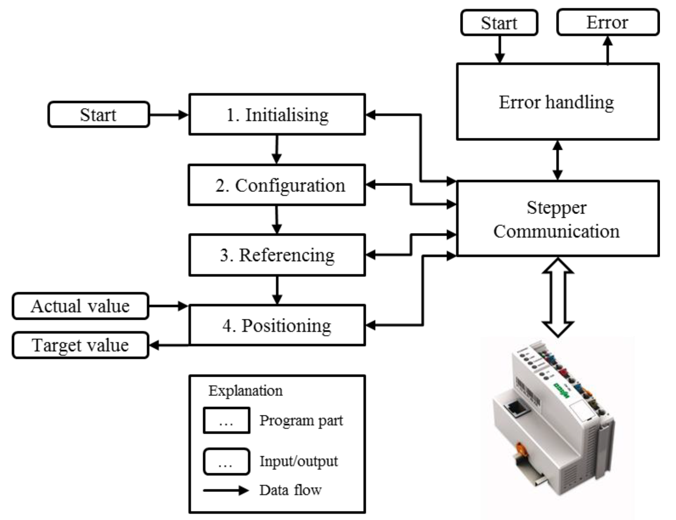
4.1. Program Structure

- Error handling
- Initializing
- Configuration
- Referencing
- Positioning
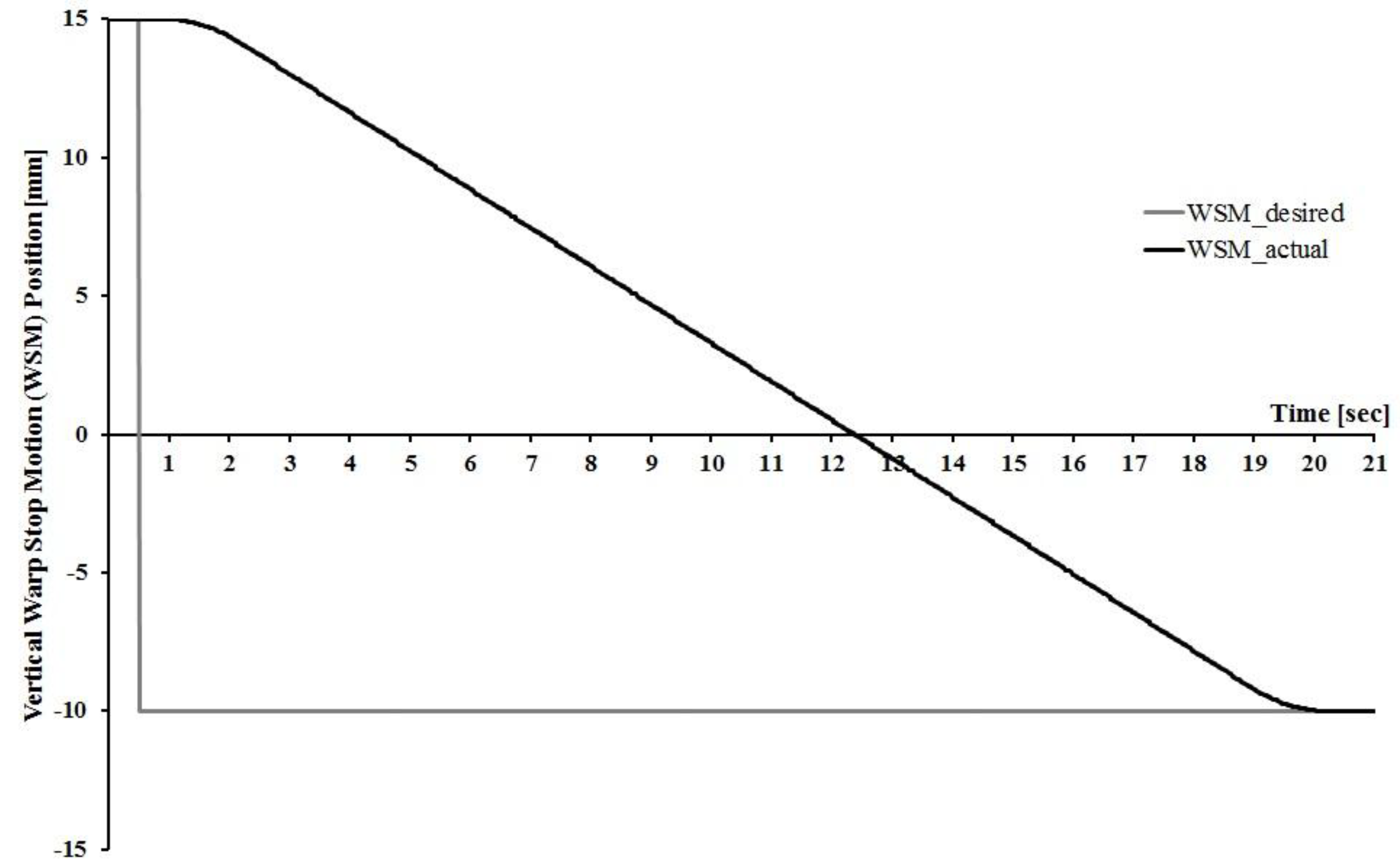
4.2. Functional Validation
| Task | Repetition Frequency |
|---|---|
| Initializing | 50 Hz |
| Configuration | 50 Hz |
| Referencing | 20 Hz |
| Positioning | 50 Hz |
| Error readout and acknowledge | 2 Hz |
| Stepper Communication | 50 Hz |
5. Conclusions
Acknowledgments
Author Contributions
Conflicts of Interest
References
- Adanur, S. Handbook of Weaving; CRC Press: Boca Raton, FL, USA, 2001. [Google Scholar]
- Osthus, T. Prozessoptimierung in der Weberei durch automatische Einstellung von Streichbaum und Kettfadenwächterkorb. Ph.D. Thesis, RWTH Aachen University, Aachen, Germany, 1996. [Google Scholar]
- Gloy, Y.-S.; Büllesfeld, R.; Islam, T.; Gries, T. Application of a Smith Predictor for Control of Fabric Weight during Weaving. J. Mech. Eng. Autom. 2013, 3, 29–37. [Google Scholar]
- Grote, K.-H.; Felhusen, J. Dubbel—Taschenbuch für den Maschinenbau, 23rd ed.; Springer: Berlin, Heidelberg, Germany, 2011. [Google Scholar]
- De Weldige, E. Prozesssimulation der Kettfadenzugkräfte in Webmaschinen. Ph.D. Thesis, RWTH Aachen University, Aachen, Germany, 1996. [Google Scholar]
- Beckhoff Automation GmbH. AS1030 Stepper Motor. Available online: http://download.beckhoff.com/download/Document/Catalog/Main_Catalog/english/separate-pages/Drive_Technology/AS1030.pdf (accessed on 27 November 2014).
- Beckhoff Automation GmbH. Stepper Motors AS1010, AS1020, AS1030, AS1050, AS1060 Documentation. Available online: http://download.beckhoff.com/download/Document/Drives/AS1000_en.chm (accessed on 27 November 2014).
- Jacobs, G. Maschinengestaltung; Schumacher-Verlag: Herzogenrath, Germany, 2010; Volume 1. [Google Scholar]
- WAGO Kontakttechnik GmbH & Co. KG. Available online: https://eshop.wago.com/JPBC/0_5StartPage.jsp?TopNavi=0_6TopNavi.jsp&Zone=2&HauptframH=%2FJPBC%2FCommonPageHandler.jsp&activatedPage=SEARCHPAGE (accessed on 27 November 2014).
- WAGO Kontakttechnik GmbH & Co. KG. Available online: https://eshop.wago.com/JPBC/0_5StartPage.jsp;jsessionid=659553D97D42555AF854B912D7A4E93A?supplierAID=750-672&catalogID=WAGO01&zone=7 (accessed on 27 November 2014).
- WAGO Kontakttechnik GmbH & Co. KG. Available online: http://www.wago.com/wagoweb/documentation/750/ger_manu/modules/m07500672_00000000_0de.pdf (accessed on 27 November 2014).
- WAGO Kontakttechnik GmbH & Co. KG. Available online: http://www.wago.ch/de/branchenloesungen/gebaeudetechnik/gebaeudeautomation/schnittstellen/modbus-tcpip/index.jsp (accessed on 11 November 2014).
© 2015 by the authors; licensee MDPI, Basel, Switzerland. This article is an open access article distributed under the terms and conditions of the Creative Commons Attribution license (http://creativecommons.org/licenses/by/4.0/).
Share and Cite
Cloppenburg, F.; Gloy, Y.-S.; Gries, T. Realization of an Automated Vertical Warp Stop Motion Positioning. Actuators 2015, 4, 2-16. https://doi.org/10.3390/act4010002
Cloppenburg F, Gloy Y-S, Gries T. Realization of an Automated Vertical Warp Stop Motion Positioning. Actuators. 2015; 4(1):2-16. https://doi.org/10.3390/act4010002
Chicago/Turabian StyleCloppenburg, Frederik, Yves-Simon Gloy, and Thomas Gries. 2015. "Realization of an Automated Vertical Warp Stop Motion Positioning" Actuators 4, no. 1: 2-16. https://doi.org/10.3390/act4010002