
Deployable Structures Based on Non-Flat-Foldable and Non-Developable Origami with Constant Curvature
School of Mechanical Engineering and Automation, Beihang University, Beijing 100191, China
*
Author to whom correspondence should be addressed.
Actuators 2024, 13(4), 156; https://doi.org/10.3390/act13040156
Submission received: 20 March 2024
/
Revised: 10 April 2024
/
Accepted: 18 April 2024
/
Published: 19 April 2024
(This article belongs to the Special Issue Actuators in 2024)
Abstract
:Deployable structures based on origami are widely used in the application of actuators. In this paper, we present a novel family of origami-based deployable structures with constant curvature. Two categories of non-flat-foldable and non-developable degree-4 vertices (NFND degree-4 vertices) are introduced. Pyramid structures are constructed based on the NFND degree-4 vertices. Doubly symmetric and singly symmetric spherical origami tubular cells (SOTCs) are established based on pyramid structures. To construct deployable origami modules using SOTCs, linking units are introduced. The mobility of the SOTCs and origami modules is analyzed using constraint screws. To realize the construction and simulation of deployable structures, kinematic and geometric analyses of the doubly symmetric and singly symmetric SOTCs are performed. Finally, we introduce four cases for deployable structures in spherical actuators based on the combination of multiple origami modules. These case studies demonstrate the potential of these deployable origami structures in the design of spherical actuators.
1. Introduction
Deployable structures have the ability to fold compactly for convenient storage and transportation and then expand into specific configurations, effectively achieving a large working space [1,2]. In recent years, deployable structures have been studied and applied in the field of actuators for robotics [3,4], aerospace [5,6,7], and medical devices [8,9], where tasks require accurate positioning and adaptability.
Many researchers have dedicated their efforts to the study of deployable structures, focusing on their applications as actuators. Suthar et al. [10] introduced a multi-strand parallel twisted-scissor deployable structure with linear expansion capability. This deployable structure was utilized as an actuator for a deployable and foldable arm on a small platform. Wu et al. [11] proposed a quadrangular truss-shaped deployable structure with metamorphic mobility for a robotic manipulator, enabling both deployment and grasping movements. Gao et al. [12] designed a three-fingered robotic grasper based on deployable structures. The capability to grasp spherical objects and various shapes was demonstrated through experimental validation. A large deployable structure with the capability to form a spherical shape for actuator applications in the aerospace industry was proposed by Chu et al. [13]. Huang et al. [14] developed a method for the design of a large, spherical surface-deployable structure that can be utilized as an actuator for antennas. The proposed deployable structure was constructed using irregularly shaped triangular prismoid units. Based on two-layer and two-loop spatial linkage units with 4R coupling chains, a family of novel umbrella-shaped deployable structures was introduced by Cao et al. [15]. The novel deployable structures have the ability to form an umbrella-shaped surface when deployed, making them suitable for actuator applications in various engineering fields.
Origami, the traditional art of folding paper, can be applied to the design of deployable structures, particularly for actuators [16,17,18,19]. Soft pneumatic actuators inspired by the accordion pattern with linear motion were proposed by Zaghloul et al. [20]. The design, fabrication, and testing of origami-inspired soft pneumatic actuators were presented. Zhang et al. [21] introduced the design, analysis, and experimental validation of a novel pneumatic/cable-driven hybrid linear actuator based on the Kresling pattern. The proposed linear actuators had several advantages over traditional actuators, such as extension ratio and easily controlled position. Liu et al. [22] employed the folding technique of the Kresling pattern to develop a linear actuator that exhibited several beneficial characteristics, including low driving pressure, high deployable ratio, and fast response. Yu et al. [23] developed pneumatic foldable actuators with the ability of linear and turning movements based on Miura-ori. The novel actuator with bending motions was proposed by Seo et al. [24] based on the Yoshimura pattern, which could be utilized to assist the upper limb motion. Jeong et al. [25] presented an actuator with screw motion based on an origami twisted tower, adopted for the three-finger robotic manipulator. The actuator inspired by the Waterbomb pattern was developed by Li et al. [26] to be used as a soft robotic gripper. The origami gripper with a hollow hemispherical shape was driven by inflation and offered remarkable adaptability and robustness, enabling it to lift a wide range of objects efficiently. Chen et al. [27,28,29,30] conducted extensive studies on deployable structures utilizing degree-4 vertices. Their investigation focused on the design of origami tubular structures based on zero-thickness panels, as well as designs considering the thickness of the panels. The proposed methods of deployable structures hold great potential for application in actuators.
Based on the research described above, it can be seen that many actuators have been designed based on developable structures. Most of the current studies on actuators concentrate on linear or planar motion. However, there is limited research on actuators specifically designed to move on a spherical surface with a constant radius. In this paper, a design method for obtaining the spherical origami tubular cells with a constant radius is presented based on non-flat-foldable and non-developable degree-4 vertices. Furthermore, we use these origami cells in the design of origami modules and introduce a family of design models for spherical actuators. The main contributions of this paper are as follows: These deployable structures with a constant radius offer versatility and adaptability, making them applicable to a wide range of applications in different industries. The proposed spherical actuators have significant potential for practical applications in various fields, including antennae, solar arrays, robotic graspers, etc.
The organization of this paper is structured as follows: Section 2 presents the design of deployable spherical origami tubular cells and modules, followed by a comprehensive analysis of their mobility. The kinematics and geometry of spherical origami tubular cells are analyzed in Section 3. In Section 4, four cases are studied to validate the design of deployable structures in spherical actuators based on the combination of multiple origami modules. Conclusions are presented in the Section 5.
2. Design of Deployable Spherical Origami Tubular Cells and Modules
In this section, a novel spherical origami tubular cell (SOTC) is presented based on the non-flat-foldable and non-developable degree-4 vertex (NFND degree-4 vertex). To develop a novel family of deployable structures with constant curvature during the folding motion, many origami modules are presented by assembling the origami tubular cell. The mobility analysis of SOTCs and origami modules is performed.
2.1. Origami-Based Tubular Cells
The degree-4 vertex consists of four panels and four creases that intersect at a single vertex, as shown in Figure 1. The sector angle of a panel between two creases is commonly denoted by . The folding angle of the i-th crease is denoted by . For the mountain crease, the range of folding angle is within . For the valley crease, the range of folding angle is within . All folding angles are equal to in the fully folded state. A degree-4 vertex is considered flat-foldable when the folding angle of each crease is transformed into the fully folded state. When the folding angle of each crease is 0 simultaneously in the unfolded state, the degree-4 vertex is developable [31]. The conditions for flat-foldability and developability are [32,33]: (a) Maekawa Theorem: the difference between the number of mountain creases and valley creases is equal to ±2, that is, M − V = ±2; (b) Kawasaki Theorem 1: the sum of sector angles of opposite panels is , i.e., . Based on whether the crease can be unfolded into the flat state () and folded into the fully folded state (), there are four categories of degree-4 vertices: flat-foldable and developable degree-4 vertex, non-flat-foldable and developable degree-4 vertex, flat-foldable and non-developable degree-4 vertex, and non-flat-foldable and non-developable degree-4 vertex.
When the sector angles of the degree-4 vertex are satisfied , , and (), the degree-4 vertex is non-flat-foldable and non-developable, with all the creases being mountain creases, as indicated in Figure 2. During the folding motion, the four creases consistently move on a spherical surface with a constant radius, forming a symmetric convex configuration. Due to this property, the NFND degree-4 vertex is utilized to design a novel origami tubular cell for constructing deployable structures with constant curvature. Based on their symmetry, the NFND degree-4 vertices are categorized as doubly symmetric NFND degree-4 vertex and singly symmetric NFND degree-4 vertex. In the doubly symmetric NFND degree-4 vertex, , i.e., . The doubly symmetric NFND degree-4 vertex exhibits symmetry in both plane 1, formed by creases 1 and 3, and plane 2, formed by creases 2 and 4. When , the NFND degree-4 vertex is singly symmetric. The singly symmetric NFND degree-4 vertex exhibits symmetry only within plane 1 defined by creases 1 and 3.
Isosceles triangular panels are selected as constituent panels in two categories of NFND degree-4 vertices to form pyramid structures. As illustrated in Figure 3, the doubly symmetric pyramid is presented when the geometric parameters of all isosceles triangular panels are the same, i.e., , , and . The singly symmetric pyramid is composed of two types of isosceles triangular panels, as shown in Figure 4. The first and fourth panels are panel T1, and the second and third panels are panel T2. The geometric parameters of the singly symmetric pyramid are , , , , and . The folding motion of the pyramid is shown in Figure 5.
To present the SOTC, we remove specific sections of the four panels from the two types of pyramid structures. The removed sections are four isosceles triangular panels with the same length of sides, i.e., . The initial constituent panels are transformed into isosceles trapezoidal panels. Doubly symmetric and singly symmetric SOTCs are shown in Figure 6. During the folding motion, upper points C, D, E, and F always move on a sphere with radius R1, and lower points C’, D’, E’, and F’ always move on a sphere with radius R2 = R1−r.
2.2. Construction of Deployable Origami Modules
To achieve the modular design of deployable structures, origami modules are proposed through the combination of SOTCs using a kind of linking unit (LU). In the linking unit, two components, C1 and C2, are connected by one rotational joint. The component is constructed by rigidly connecting several isosceles trapezoidal panels. The number of isosceles trapezoidal panels in C1 and C2 is determined by the number and combination of SOTCs. Considering the requirements for combination, each component can be individually customized in design. With this design principle as a foundation, the design of a wide range of LUs can be realized.
Figure 7 illustrates three types of linking units: LU1, LU2, and LU3. As shown in Figure 7a, during the motion process, there are four distinct regions between two components in LU1. Due to the constraint between the components of LU1, the range of the folding angle is limited to [0, π]. There are six regions between two components in LU2, as indicated in Figure 7b. Similarly, the constraint between the components of LU2 limits the range of the folding angle to the interval [0, 2π/3]. In LU3, eight regions are formed between the two components in Figure 7c. Likewise, for LU3, the range of folding angle is [0, π/2] due to the constraint between its components. All the formed regions can be connected to the basic cells to create novel modules.
SOTCs are assembled by the linking unit. The panels of SOTCs connected by the same component of the LU always maintain synchronized motion throughout the entire motion process.
As depicted in Figure 8, it is possible to construct two deployable origami modules using LU1. One module, called OM1_L1, is designed by assembling two SOTCs. In OM1_L1, the folding angle of the shared crease in the first cell and the second cell remains consistent. Additionally, assembling four SOTCs allows for the creation of another origami module, referred to as OM1_L2. The folding angle of the shared crease in the first cell and the second cell remains equal to each other, as does the folding angle in the third cell and the fourth cell. Moreover, the folding angle of the shared crease in the first cell and the third cell are always complementary to each other, as are the angles of the shared crease in the second cell and the fourth cell.
As shown in Figure 9, LU2 is used to assemble three SOTCs, resulting in the origami module OM3. The folding angle of the shared crease remains consistent across the three SOTCs and falls within the interval of [π/3, π]. LU3 is utilized to assemble four SOTCs, creating the origami module OM4. The folding angle of the shared crease remains consistent across the four SOTCs, and it ranges from π/2 to π.
2.3. Mobility Analysis Using Constraint Screws
2.3.1. Mobility of the SOTC
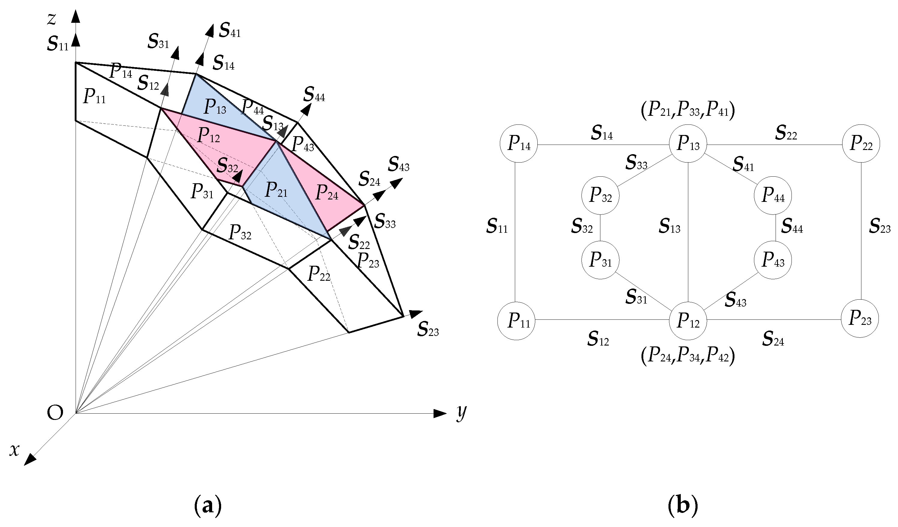
As illustrated in Figure 10, the axes of the SOTC’s four creases intersect at a common point O. The panels of the SOTC are described as P1i, . In rigid origami, the creases and panels can be treated as revolute joints and linkages [34]. The equivalent kinematic mechanism of the SOTC is a spherical 4R linkage. The topology of this mechanism is a closed single-loop chain. S1, S2, S3, and S4 are the twists of the four creases of the SOTC. To analyze the mobility of this linkage, the coordinate frame attached at point O is set as the global frame. The z-axis is along the axis of S1, and the y-axis is perpendicular to the z-axis and coplanar with the axis of S3. The x-axis is determined using the right-handed rule.
The motion screws of the SOTC’s equivalent mechanism, expressed in the global frame, are represented as follows:
Based on the screw theory, it can be concluded that there are three constraint screws in the SOTC. They can be expressed as follows:
According to the modified Kutzbach–Grübler mobility formula [35], the degree of freedom is calculated as follows:
where DoF is the degree of freedom of mechanism, d is the rank of the mechanism, n represents the number of links in the mechanism, g represents the number of joints, is the degree of freedom of the i-th crease, is the number of redundant constraints, and represents the local degree of freedom.
According to Equations (2) and (3), the rank of the mechanism is d = 6 − 3 = 3. Based on the given information of having four links and four joints and no redundant constraints or local mobility, the degree of freedom of SOTC is calculated as follows:
This means that the SOTC has only one degree of freedom.
The constraint screws indicate that forces along the x-axis restrict movement in that direction, while forces along the y-axis and z-axis limit movement accordingly in those respective directions. Therefore, the SOTC has only one rotational degree of freedom around an axis passing through the center of the sphere. The endpoints C, D, E, and F on the SOTC move on the surface of the outer sphere with a radius of R1. Similarly, the points C’, D’, E’, and F’ on the SOTC move on the surface of the inner sphere with a radius of R2. The variation in distances between points on the cell enables the SOTC to have the functionality of contraction and expansion while maintaining a constant curvature.
2.3.2. Mobility Analysis of Deployable Origami Modules
As shown in Figure 11, OM1_L1 is a multi-closed-loop mechanism. There are seven motion screws in OM1_L1. The motion screws of OM1_L1, expressed in the global frame, is represented as follows:
There are three constraint screws as follows:
The rank of OM1_L1 is d = 6 − 3 = 3. Based on the information of having six links and seven joints and no redundant constraints or local mobility, the degree of freedom of OM1_L1 is calculated as follows:
It is evident that the constraint screw system of OM1_L1, comprising two combined SOTCs, is identical to that of a single SOTC. They possess the same degree of freedom, exhibiting the same spherical motion. Consequently, if more OM1_L1s are assembled by LU1, the proposed deployable origami structures retain a single degree of freedom.
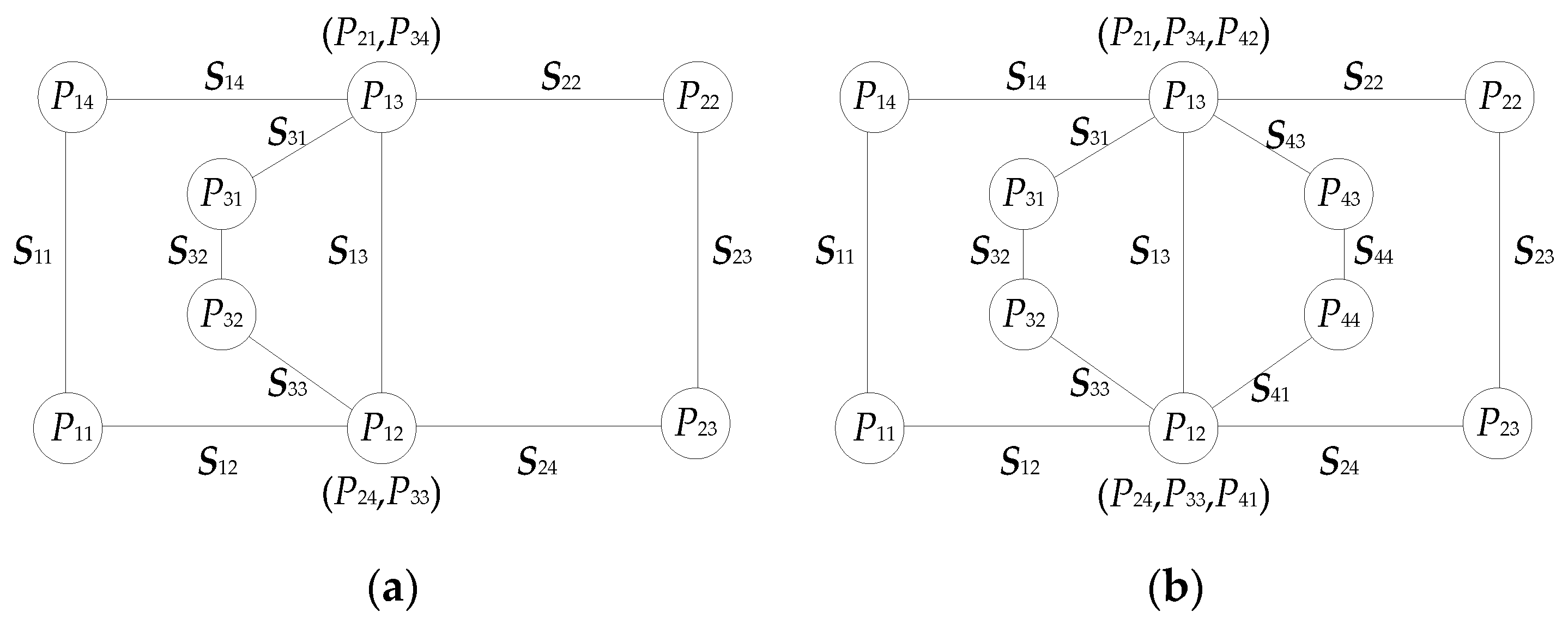
Similarly, the mobility analysis of OM1_L2, OM3, and OM4 are presented. The constraint screw systems of OM1_L2, OM3, and OM4 are identical to that of OM1_L1. The rank of OM1_L2, OM3, and OM4 is d = 6 − 3 = 3. In Figure 12, there are 10 links and 13 joints and no redundant constraints or local mobility. The degree of freedom of OM1_L2 is calculated as follows:
In Figure 13a, there are eight links and ten joints and no redundant constraints or local mobility. The degree of freedom of OM3 is calculated as follows:
In Figure 13b, the topology diagram of OM4 is similar to that of OM1_L2. The degree of freedom of OM4 is 1.
3. Kinematic Analysis and Geometry of SOTCs
To facilitate the design of various deployable structures, the kinematics of SOTCs are analyzed. The relationships between the folding angles of two SOTCs are derived, allowing for a description of the geometry of these SOTCs based on their respective folding angles.
3.1. The Explicit Solutions to Input–Output Equations of SOTC
The equivalent mechanism of the SOTC is utilized for kinematic analysis. The twist system of the SOTC is proposed using Equation (1). In the doubly symmetric, it is expressed as follows:
The kinematic input–output equation of the doubly symmetric SOTC is
where is the folding angle of the i-th crease, and is the unit matrix.
Substituting Equation (10) into Equation (11), the following equations are obtained:
The range of folding angles of four creases in the doubly symmetric SOTC is .
The relationships between folding angles in the singly symmetric SOTC are given as follows:
When , it is deduced that , , , and cannot be equal to . The singly symmetric SOTC achieves a stable configuration when , as indicated in Figure 14. The two panels are flat, and reaches the minimum.
3.2. Geometry of SOTCs
3.2.1. Geometry of Doubly Symmetric SOTC
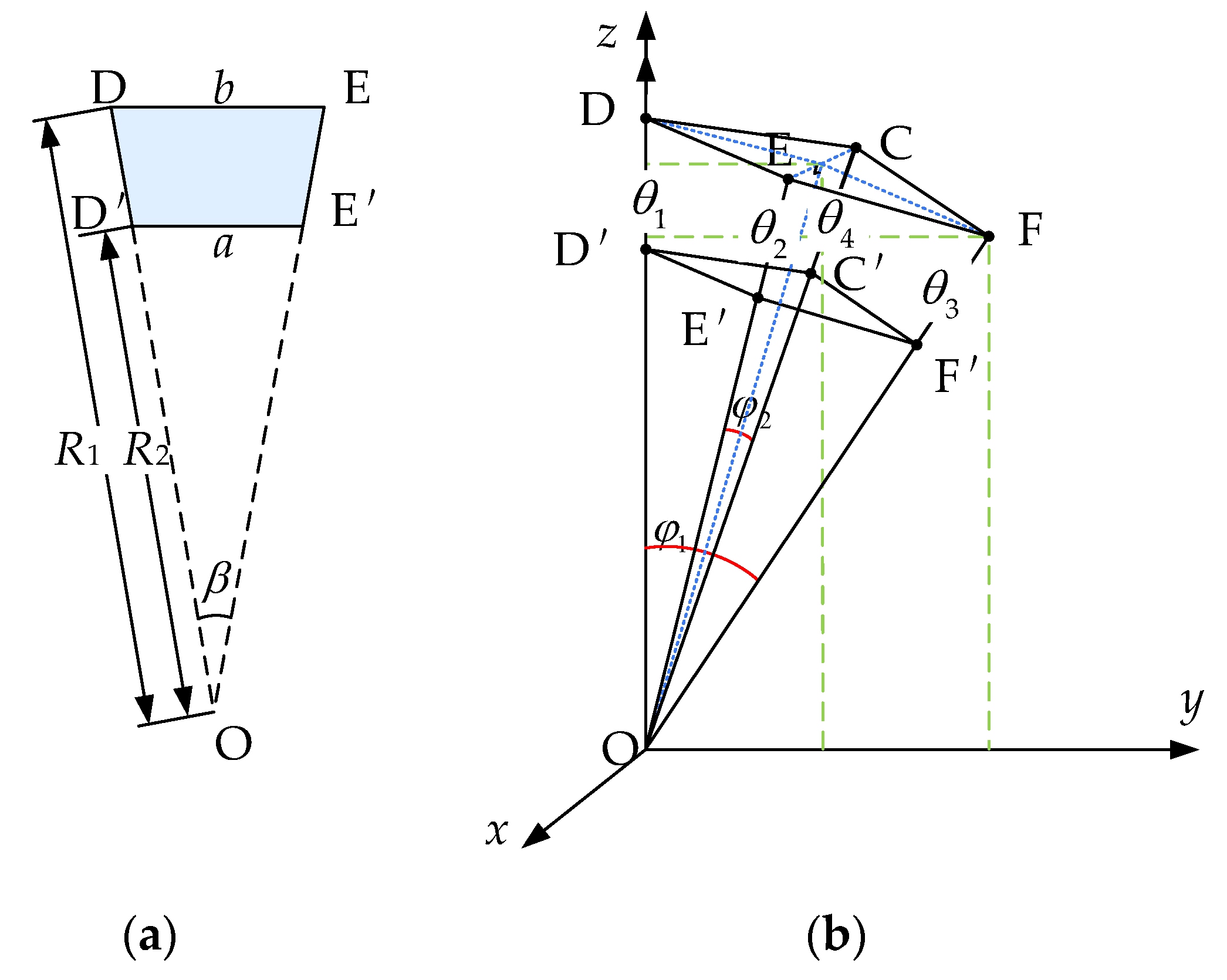
The doubly symmetric SOTC is composed of four identical isosceles trapezoid panels, as shown in Figure 15a. The geometric parameters of the isosceles trapezoid panel are a, b, and . The kinematic parameters are input and output . With three geometric parameters and two kinematic parameters, the configuration of the doubly symmetric SOTC is completely determined. In Figure 15b, two edge angles, and , now exist, which are related to the folding angles and . The following three relationships are established between folding and edge angles [36]:
As shown in Figure 15, the radii of the singly symmetric SOTC’s motion trajectories are as follows:
The coordinates of each point of doubly symmetric SOTC are expressed as follows:
It is derived that
3.2.2. Geometry of Singly Symmetric Origami Tubular Cell
The singly symmetric SOTC is composed of two types of isosceles trapezoid panels, as shown in Figure 16a. The geometric parameters of the first isosceles trapezoid panel are a1, b1, and . The geometric parameters of the second isosceles trapezoid panel are a2, b2, and . To ensure that points C, D, E, and F move on a sphere with a radius of R1, and points C’, D’, E’, and F’ move on a sphere with a radius of R2, the geometric parameters of two types of panels need to satisfy the following relationship:
With geometric parameters a1, b1, , and ; input folding angle ; and output folding angle , the configuration of the singly symmetric SOTC is completely determined. As shown in Figure 16b, two edge angles, and , now exist, which are related to the folding angles and . The following relationships are established between folding and edge angles:
As depicted in Figure 16, the radii of the motion trajectories are as follows:
The coordinates of four points of the singly symmetric SOTC are described in Equation (18). It is derived that
Based on the kinematics and geometry of SOTCs, it is known that the upper and lower endpoints of SOTCs are capable of moving along two spherical surfaces that share the same center. The radii of two spheres are determined using the geometric parameters of the constituent panels. According to the provided coordinates, constructions and simulations can be carried out for a variety of deployable structures in any desired configuration.
4. Case Studies for Deployable Structures in Spherical Actuators
In this section, four cases for deployable structures in spherical actuators are presented. Deployable structures are designed based on four deployable origami modules. The designed deployable structures can expand and contract to form a sphere while maintaining a consistent radius. The feasibility of creating spherical structures with constant curvature based on SOTC is validated.
4.1. Case 1
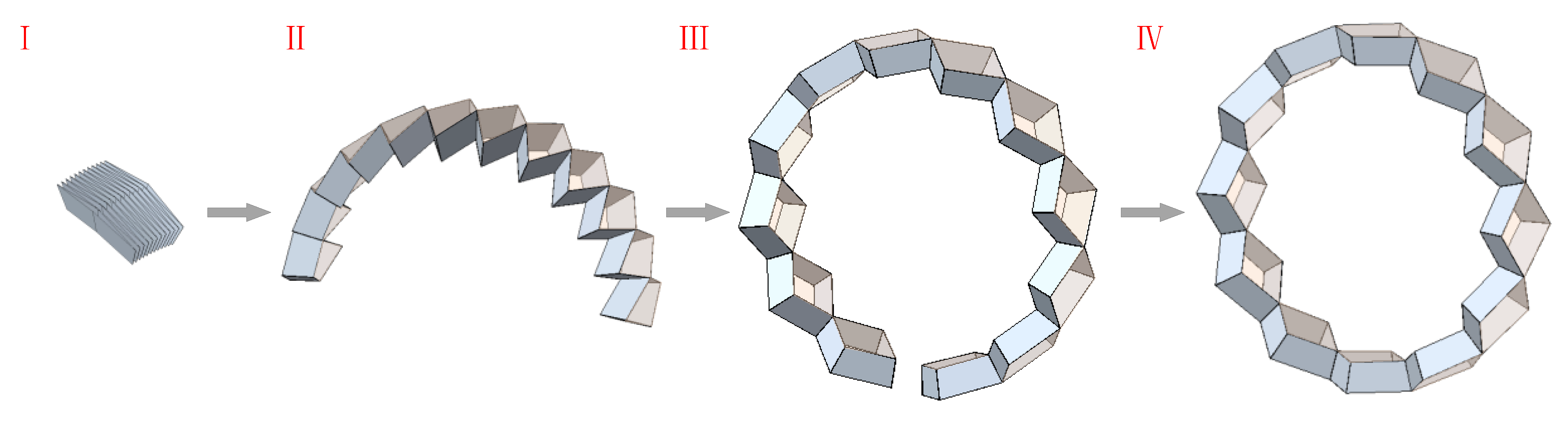
As illustrated in Figure 17, doubly symmetric SOTCs are assembled into OM1_L1 first. OM1_L1 is always symmetric about the xoz and yoz planes. Assuming the geometric parameters of the isosceles trapezoid panels in the doubly symmetric SOTC are as follows: a = 80, b = 100, and . A monolayer spherical deployable origami structure is constructed using twelve doubly symmetric SOTCs, named MSDOS. It is proven that the motion trajectory of the upper endpoints of this spherical deployable origami structure on the yoz plane forms a circle with a constant radius, R1 = 287.94. The edge angle of each SOTC is when two sides of the structure touch each other at the bottom in state (Ⅳ), as shown in Figure 17. According to Equations (14)–(16), the kinematic parameters in each SOTC are determined as and . Moreover, this structure exhibits versatility in its applications. Not only can it function as an actuator, but it can also be integrated as a crucial component in the assembly of more intricate actuator systems.
4.2. Case 2
To enhance the stability of the deployable origami structure, we propose the combination of OM1_L2s to develop a bilayer spherical deployable origami structure, named BSDOS, as shown in Figure 18. The BSDOS is composed of 28 identical doubly symmetric SOTCs. The geometric parameters of the SOTCs in the BSDOS are the same as those of the MSDOS. OM1_L2 is always symmetric about the xoz and yoz planes, as illustrated in Figure 8b. The kinematic parameters of the first and second cells are always identical, as well as the kinematic parameters of the third and fourth cells. The folding angle of the j-th crease in the i-th cell of OM1_L2 is denoted as (). The relationship between the folding angles of four SOTCs in OM1_L2 can be represented as follows:
The motion trajectory of the upper endpoints of this BSDOS on the yoz plane also forms a circle with a constant radius, R1 = 287.94. The edge angle of the first and second cells in each OM1_L2 is when two sides of the BSDOS touch each other at the bottom in state (Ⅳ), as shown in Figure 18. According to Equations (14)–(16), the kinematic parameters in each SOTC are determined as , , , and .
The enveloping surface of this structure is larger compared to the MSDOS. This increased size enables the deployable origami structures to cover a larger area or volume, providing more space for deployment and functionality. By expanding the enveloping surface, the bilayer spherical deployable origami structure can be utilized as an actuator to accommodate larger objects or incorporate additional components within its structure.
4.3. Case 3
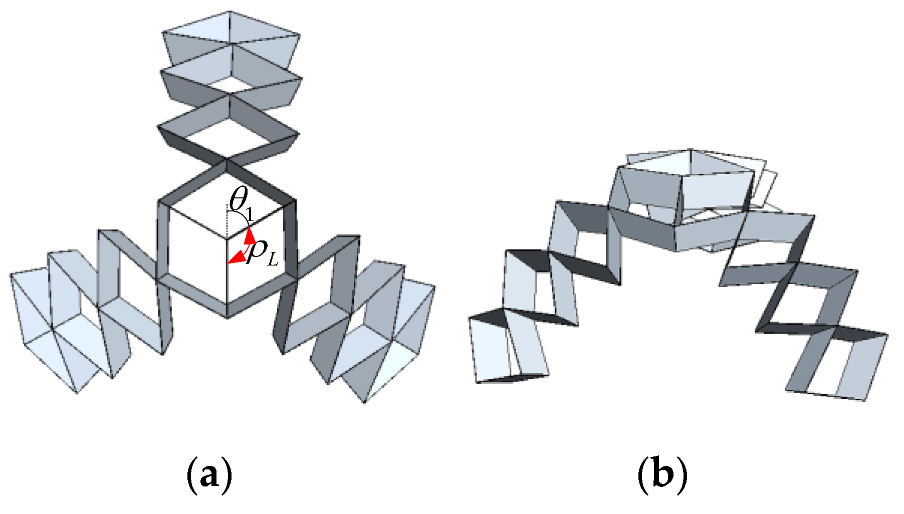
Based on OM3, a spherical deployable origami structure with three branches is proposed, named SDOS3. With the increase in the folding angles and , SDOS3 can be deployed to approximate a spherical shape. If SDOS3 is constructed by the same doubly symmetric SOTCs with geometric parameters a = 80, b = 100, and , each branch of this SDOS3 maintains a consistent curvature while unfolding and folding, ensuring predictable deployment on a sphere with a fixed radius R1 = 287.94.
Because of the shape of LU2’s components, the range of dihedral angles between two components is . When reaches its maximum, the branches of SDOS3 cannot be folded compactly. As depicted in Figure 19. The SDOS3 comprised by the same doubly symmetric SOTCs is a stable structure when .
To improve the folding ratio of SDOS3 and minimize its volume when folded, we can construct OM3 by connecting three singly symmetric SOTCs. This OM3 can be further assembled with three monolayer spherical deployable origami structures, resulting in the creation of SDOS3 with a high folding ratio. There are one singly symmetric SOTC and five doubly symmetric SOTCs in each branch. The parameters of singly symmetric SOTCs are derived based on Equations (20) and (23). Let the geometric parameters of SDOS3 be a1 = 105.66, b1 = 132.08, , a2 = 80, b2 = 100, and , its kinematic simulation is illustrated in Figure 20. The edge angle of singly symmetric SOTC is the sum of and . The edge angle of doubly symmetric SOTC is equal to . The angles and satisfy when three branches of the structure touch each other at the bottom in state (Ⅳ), as shown in Figure 20. The kinematic parameters in singly symmetric SOTC are determined as , , . The kinematic parameters in each doubly symmetric SOTC are and . The ability of SDOS3 to deploy and collapse along a spherical surface enables accurate movements, offering the potential for diverse applications in spherical actuators.
4.4. Case 4
In Figure 21, a spherical deployable origami structure with four branches is proposed, named SDOS4. OM4 is constructed by connecting four singly symmetric SOTCs at first. OM4 is further assembled with four monolayer spherical deployable origami structures, resulting in the creation of the SDOS4 with a high folding ratio. There are one singly symmetric SOTC and four doubly symmetric SOTCs in each branch. With the increase in the folding angles and , SDOS4 can also be deployed to approximate a spherical shape. In this SDOS4, a1 = 115.06, b1 = 143.83, , a2 = 80, b2 = 100, and . The angles and satisfy when four branches of the structure touch each other at the bottom in state (Ⅳ), as shown in Figure 21. According to Equations (21) and (22), the kinematic parameters in the singly symmetric SOTC are , , and . The kinematic parameters in each doubly symmetric SOTC are and . SDOS4 is similar to SDOS3 and can be utilized in the design of spherical actuators.
By designing individual linking units, it is possible to construct deployable origami structures with numerous branches. These structures can be deployed with a consistent curvature, making them suitable for creating intricate and adaptable origami-based structures. They have the ability to achieve specific movements to perform various tasks. The proposed structures have the potential to be used in the design of spherical actuators.
5. Conclusions
The design and analysis of a novel family of origami-based spherical deployable structures were systematically investigated in this paper. A NFND degree-4 vertex was introduced to satisfy the requirement of curve surface configurations with constant curvature. Four isosceles triangular panels were used as constituent panels in two categories of NFND degree-4 vertices to form pyramid structures. By removing specific sections of these pyramid structures, doubly symmetric and singly symmetric SOTCs were presented. Three linking units were proposed to assemble SOTCs. Four cases of spherical origami modules were introduced by assembling SOTCs using three linking units. The mobility analysis of SOTCs and four origami modules was developed, showing that both the SOTCs and the origami modules had a degree of freedom of one. It can be deduced that the mobility of the proposed spherical deployable structures is one. The kinematic and geometric analyses of doubly symmetric and singly symmetric SOTC were performed. Based on the combination of multiple origami modules, the design of spherical structures with consistent curvature was realized. Finally, four cases were presented for deployable structures in spherical actuators. Monolayer and bilayer spherical deployable origami structures were generated. Utilizing monolayer spherical deployable origami structures and OM3 and OM4, two case studies were proposed, demonstrating spherical deployable origami structures with varying numbers of branches. The unique ability of these SDOSs to move along a spherical surface with a constant radius is a key characteristic that enables them to effectively adapt to diverse application requirements, particularly in the design of spherical actuators.
Supplementary Materials
The following supporting information can be downloaded at: https://www.mdpi.com/article/10.3390/act13040156/s1, Video S1: The simulation of MSDOS; Video S2: The simulation of BSDOS; Video S3: The simulation of SDOS3; Video S4: The simulation of SDOS4.
Author Contributions
Conceptualization, B.Q. and S.L. (Shengnan Lyu); methodology, B.Q. and J.W.; software, B.Q.; validation, B.Q.; formal analysis, B.Q. and S.L. (Shiwei Liu); investigation, B.Q.; resources, S.L. (Shengnan Lyu); data curation, B.Q.; writing—original draft preparation, B.Q.; writing—review and editing, B.Q. and S.L. (Shiwei Liu); visualization, B.Q.; supervision, S.L. (Shengnan Lyu); project administration, S.L. (Shengnan Lyu); funding acquisition, S.L. (Shengnan Lyu). All authors have read and agreed to the published version of the manuscript.
Funding
This work is funded by the National Natural Science Foundation of China (No. 52075016, 52222501, 52192632), the Fundamental Research Funds for the Central Universities (Grant No. YWF-23-L-904), the National Postdoctoral Program for Innovative Talents (BX20230455), and the State Key Laboratory of Robotics and Systems (HIT SKLRS-2024-KF-07).
Data Availability Statement
The datasets generated during and/or analyzed during the current study are available from the corresponding author upon reasonable request.
Conflicts of Interest
The authors declare no conflicts of interest. The funders had no role in the design of the study; in the collection, analyses, or interpretation of data; in the writing of the manuscript; or in the decision to publish the results.
References
- Guest, D.; Pellegrino, S. A New Concept for Solid Surface Deployable Antennas. Acta Astronaut. 1996, 38, 103–113. [Google Scholar] [CrossRef]
- Nelson, G.; Zimmerman, K.; Magleby, P.; Lang, J.; Howell, L. Developable Mechanisms on Developable Surfaces. Sci. Robot. 2019, 4, eaau5171. [Google Scholar] [CrossRef] [PubMed]
- Wu, S.; Ze, Q.; Dai, J.; Udipi, N.; Paulino, G.; Zhao, R. Stretchable Origami Robotic Arm with Omnidirectional Bending and Twisting. Proc. Natl. Acad. Sci. USA 2021, 118, e2110023118. [Google Scholar] [CrossRef] [PubMed]
- Zhang, L.; Zheng, Y.; Xu, Y.; Zhang, S.; Li, H.; Xu, G. A Tensegrity-Based Morphing Module for Assembling Various Deployable Structures. Mech. Mach. Theory 2022, 173, 104870. [Google Scholar] [CrossRef]
- Lyu, S.; Yao, P.; Xiao, H.; Zhang, W.; Ding, X. Approximating Cylinders with Bundle-folding Plane-symmetric Bricard Linkages. Int. J. Mech. 2022, 221, 107231. [Google Scholar] [CrossRef]
- Xiao, H.; Lyu, S.; Ding, X. Optimizing Accuracy of a Parabolic Cylindrical Deployable Antenna Mechanism Based on Stiffness Analysis. Chin. J. Aeronaut. 2019, 33, 1562–1572. [Google Scholar] [CrossRef]
- Wang, S.; Yan, P.; Huang, H.; Zhang, N.; Li, B. Inflatable Metamorphic Origami. Research 2023, 6, 0133. [Google Scholar] [CrossRef] [PubMed]
- Kuribayashi, K.; Tsuchiya, K.; You, Z.; Tomus, D.; Umemoto, M.; Ito, T.; Sasaki, M. Self-Deployable Origami Stent Grafts as A Biomedical Application of Ni-Rich Tini Shape Memory Alloy Foil. Mater. Sci. Eng. A 2006, 419, 131–137. [Google Scholar] [CrossRef]
- Bobbert, F.; Janbaz, S.; Zadpoor, A. Towards deployable meta-implants. J. Mater. Chem. B 2018, 6, 3449–3455. [Google Scholar] [CrossRef]
- Suthar, B.; Jung, S. Design and Bending Analysis of a Metamorphic Parallel Twisted-Scissor Mechanism. ASME J. Mech. Robot. 2021, 13, 040901. [Google Scholar] [CrossRef]
- Wu, Y.; Huang, H.; Yang, X.; Li, B.; Jia, G.; Cao, Q. Design and Analysis of a Quadrangular Truss-Shaped Deployable Robotic Manipulator for Grasping Large Scale Objects. In Proceedings of the 2018 IEEE International Conference on Cyborg and Bionic Systems (CBS), Shenzhen, China, 25–27 October 2018; pp. 460–465. [Google Scholar]
- Gao, C.; Huang, H.; Li, Y.; Li, B. Design and Analysis of a Three-Fingered Deployable Metamorphic Robotic Grasper. ASME J. Mech. 2022, 144, 083302. [Google Scholar] [CrossRef]
- Chu, Z.; Deng, Z.; Qi, X.; Li, B. Modeling and Analysis of a Large Deployable Antenna Structure. Acta Astronaut. 2014, 95, 51–60. [Google Scholar] [CrossRef]
- Huang, H.; Li, B.; Zhang, T.; Zhang, Z.; Qi, X.; Hu, Y. Design of Large Single-Mobility Surface-Deployable Mechanism Using Irregularly Shaped Triangular Prismoid Modules. ASME J. Mech. Des. 2019, 141, 012301. [Google Scholar] [CrossRef]
- Cao, W.; Yang, D.; Ding, H. Topological Structural Design of Umbrella-Shaped Deployable Mechanisms Based on New Spatial Closed-Loop Linkage Units. ASME J. Mech. Des. 2018, 140, 062302. [Google Scholar] [CrossRef]
- Wang, X.; Qu, H.; Li, X.; Kuang, Y.; Wang, H.; Guo, S. Multi-Triangles Cylindrical Origami and Inspired Metamaterials with Tunable Stiffness and Stretchable Robotic Arm. PNAS Nexus 2023, 2, pgad098. [Google Scholar] [CrossRef] [PubMed]
- Wang, S.; Gao, Y.; Huang, H.; Li, B.; Guo, H.; Liu, R. Design of Deployable Curved-Surface Rigid Origami Flashers. Mech. Mach. Theory 2022, 167, 104512. [Google Scholar] [CrossRef]
- Morgan, J.; Magleby, S.P.; Howell, L.L. An approach to designing origami-adapted aerospace mechanisms. J. Mech. Des. 2016, 138, 052301. [Google Scholar] [CrossRef]
- Bentley, C.; Harne, R. Deployable Linear and Spiral Array Structures Based on A Kresling-Inspired Mechanism with Integrated Scissor Arms. J. Intell. Mater. Syst. Struct. 2023, 34, 1917–1931. [Google Scholar] [CrossRef]
- Zaghloul, A.; Bone, G.M. Origami-Inspired Soft Pneumatic Actuators: Generalization and Design Optimization. Actuators 2023, 12, 72. [Google Scholar] [CrossRef]
- Zhang, Z.; Chen, G.; Wu, H.; Kong, L.; Wang, H. A Pneumatic/Cable-Driven Hybrid Linear Actuator with Combined Structure of Origami Chambers and Deployable Mechanism. IEEE Robot. Autom. Lett. 2020, 5, 3564–3571. [Google Scholar] [CrossRef]
- Liu, J.; Ma, G.; Ma, Z.; Zuo, S. Origami-Inspired Soft-Rigid Hybrid Contraction Actuator and Its Application in Pipe-Crawling Robot. Smart Mater. Struct. 2023, 32, 065015. [Google Scholar] [CrossRef]
- Yu, M.; Yang, W.; Yu, Y.; Cheng, X.; Jiao, Z. A Crawling Soft Robot Driven by Pneumatic Foldable Actuators Based on Miura-Ori. Actuators 2020, 9, 26. [Google Scholar] [CrossRef]
- Seo, S.; Park, W.; Lee, D.; Bae, J. Origami-Structured Actuating Modules for Upper Limb Support. IEEE Robot. Autom. Lett. 2021, 6, 5239–5246. [Google Scholar] [CrossRef]
- Jeong, D.; Lee, K. Design and Analysis of an Origami-Based Three-Finger Manipulator. Robotica 2017, 36, 261–274. [Google Scholar] [CrossRef]
- Li, S.; Stampfli, J.J.; Xu, H.J.; Malkin, E.; Diaz, E.V.; Rus, D.; Wood, R.J. A Vacuum-Driven Origami “Magic-Ball” Soft Gripper. In Proceedings of the 2019 International Conference on Robotics and Automation (ICRA), Montreal, QC, Canada, 20–24 May 2019; pp. 7401–7408. [Google Scholar]
- Chen, Y.; Lv, W.; Li, J.; You, Z. An Extended Family of Rigidly Foldable Origami Tubes. J. Mech. Robot. 2017, 9, 021002. [Google Scholar] [CrossRef]
- Liu, S.; Lv, W.; Chen, Y.; Lu, G. Deployable Prismatic Structures With Rigid Origami Patterns. J. Mech. Robot. 2016, 8, 031002. [Google Scholar] [CrossRef]
- Gattas, J.M.; Lv, W.; Chen, Y. Rigid-foldable tubular arches. Eng. Struct. 2017, 145, 246–253. [Google Scholar] [CrossRef]
- Lv, W.; Chen, Y.; Zhang, J. Thick-Panel Origami Tubes with Hexagonal Cross-Sections. J. Mech. Robot. 2023, 15, 051012. [Google Scholar] [CrossRef]
- Waitukaitis, S.; Dieleman, P.; Hecke, M. Non-Euclidean origami. Phys. Rev. E 2019, 102, 031001. [Google Scholar] [CrossRef]
- Kawasaki, T. On the Relation Between Mountain-Creases and Valley-Creases of A Flat Origami. In Proceedings of the 1st International Meeting of Origami Science and Technology, Ferrara, Italy, 6–7 December 1989; pp. 229–237. [Google Scholar]
- Hull, T. Counting Mountain-Valley Assignments for Flat Folds. ARS Comb. 2003, 67, 175–187. [Google Scholar]
- Dai, J.; Jones, R. Mobility in metamorphic mechanisms of foldable/erectable kinds. J. Mech. Des. 1999, 121, 375–382. [Google Scholar] [CrossRef]
- Gogu, G. Mobility of Mechanisms: A Critical Review. Mech. Mach. Theory 2005, 40, 1068–1097. [Google Scholar] [CrossRef]
- Gattas, J.; Wu, W.; You, Z. Miura-Base Rigid Origami: Parameterizations of First-Level Derivative and Piecewise Geometries. ASME J. Mech. Des. 2013, 135, 111011. [Google Scholar] [CrossRef]
Figure 1.
Degree-4 vertex, 1–4 represent the numbering of creases.

Figure 2.
NFND degree-4 vertex: (a) crease arrangements and geometric parameters, 1–4 represent the numbering of creases; (b) partially folded configurations.
Figure 2.
NFND degree-4 vertex: (a) crease arrangements and geometric parameters, 1–4 represent the numbering of creases; (b) partially folded configurations.

Figure 3.
The doubly symmetric pyramid: (a) the pyramid structure; (b) the isosceles triangular panel of the doubly symmetric pyramid; (c) geometric parameters of the doubly symmetric pyramid.
Figure 3.
The doubly symmetric pyramid: (a) the pyramid structure; (b) the isosceles triangular panel of the doubly symmetric pyramid; (c) geometric parameters of the doubly symmetric pyramid.

Figure 4.
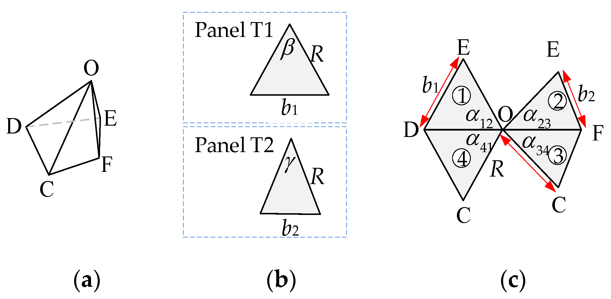
The singly symmetric pyramid: (a) the pyramid structure; (b) two types of constituent panels of the singly symmetric pyramid; (c) geometric parameters of the singly symmetric pyramid, 1–4 represent the numbering of panels.
Figure 4.
The singly symmetric pyramid: (a) the pyramid structure; (b) two types of constituent panels of the singly symmetric pyramid; (c) geometric parameters of the singly symmetric pyramid, 1–4 represent the numbering of panels.

Figure 5.
The folding motion of the pyramid structure.

Figure 6.
The SOTC: (a) constituent panels of doubly symmetric SOTC; (b) partially folded configurations of doubly symmetric SOTC; (c) constituent panels of singly symmetric SOTC; (d) partially folded configurations of singly symmetric SOTC.
Figure 6.
The SOTC: (a) constituent panels of doubly symmetric SOTC; (b) partially folded configurations of doubly symmetric SOTC; (c) constituent panels of singly symmetric SOTC; (d) partially folded configurations of singly symmetric SOTC.

Figure 7.
Three types of linking units: (a) LU1; (b) LU2; (c) LU3.

Figure 8.
Deployable origami modules constructed by LU1: (a) OM1_L1; (b) OM1_L2. 1–4 represent the numbering of SOTCs.
Figure 8.
Deployable origami modules constructed by LU1: (a) OM1_L1; (b) OM1_L2. 1–4 represent the numbering of SOTCs.

Figure 9.
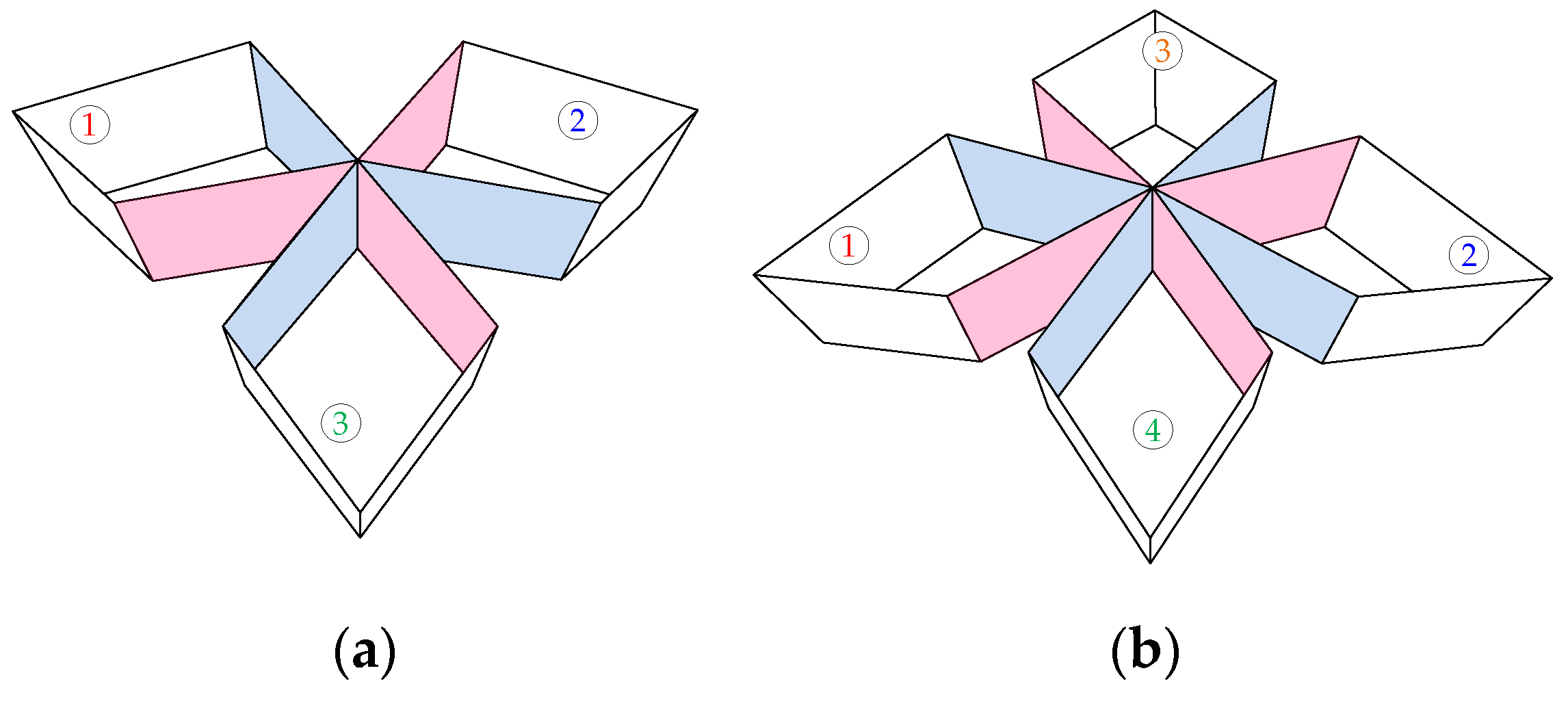
Deployable origami modules constructed by LU2 and LU3: (a) OM3; (b) OM4. 1–4 represent the numbering of SOTCs.
Figure 9.
Deployable origami modules constructed by LU2 and LU3: (a) OM3; (b) OM4. 1–4 represent the numbering of SOTCs.

Figure 10.
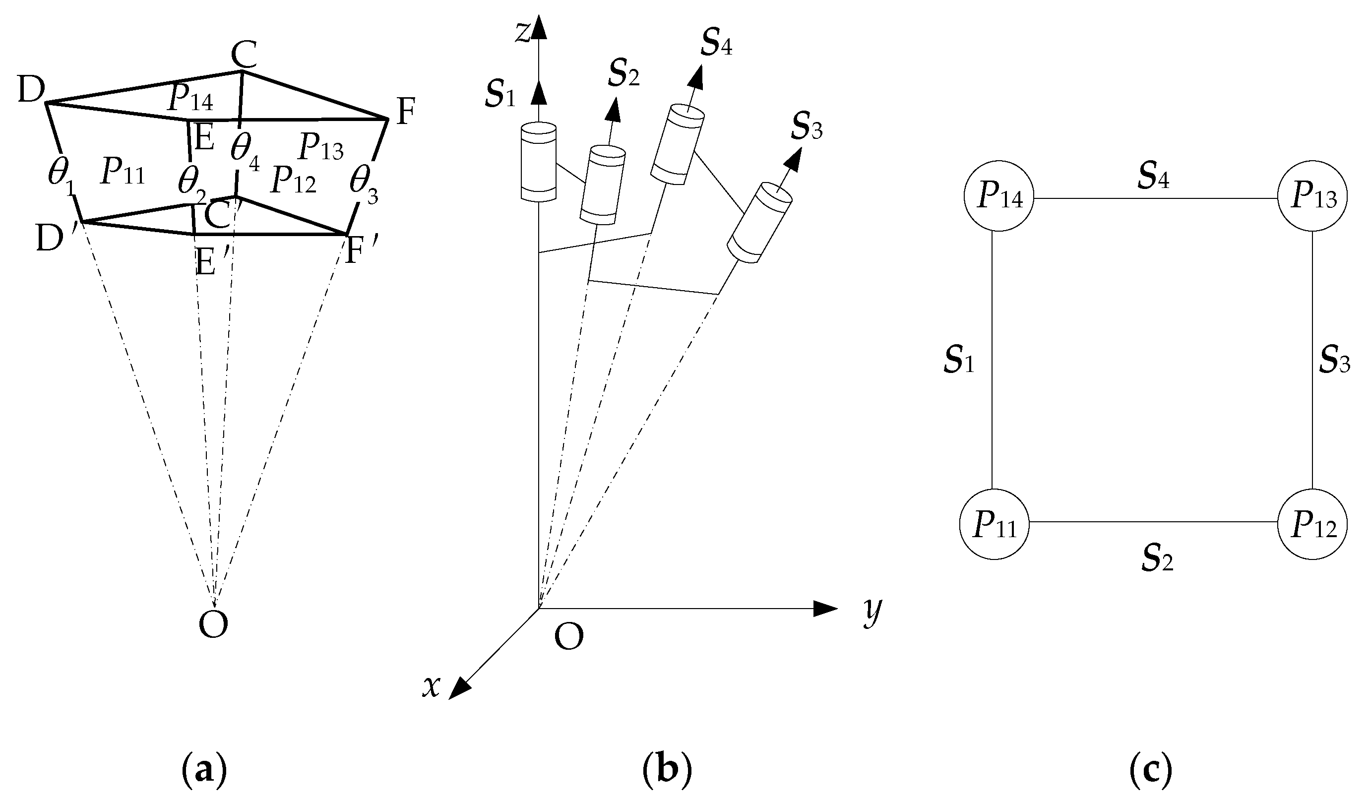
Equivalent mechanism and topology diagram of SOTC: (a) SOTC; (b) equivalent mechanism; (c) topology diagram.
Figure 10.
Equivalent mechanism and topology diagram of SOTC: (a) SOTC; (b) equivalent mechanism; (c) topology diagram.

Figure 11.
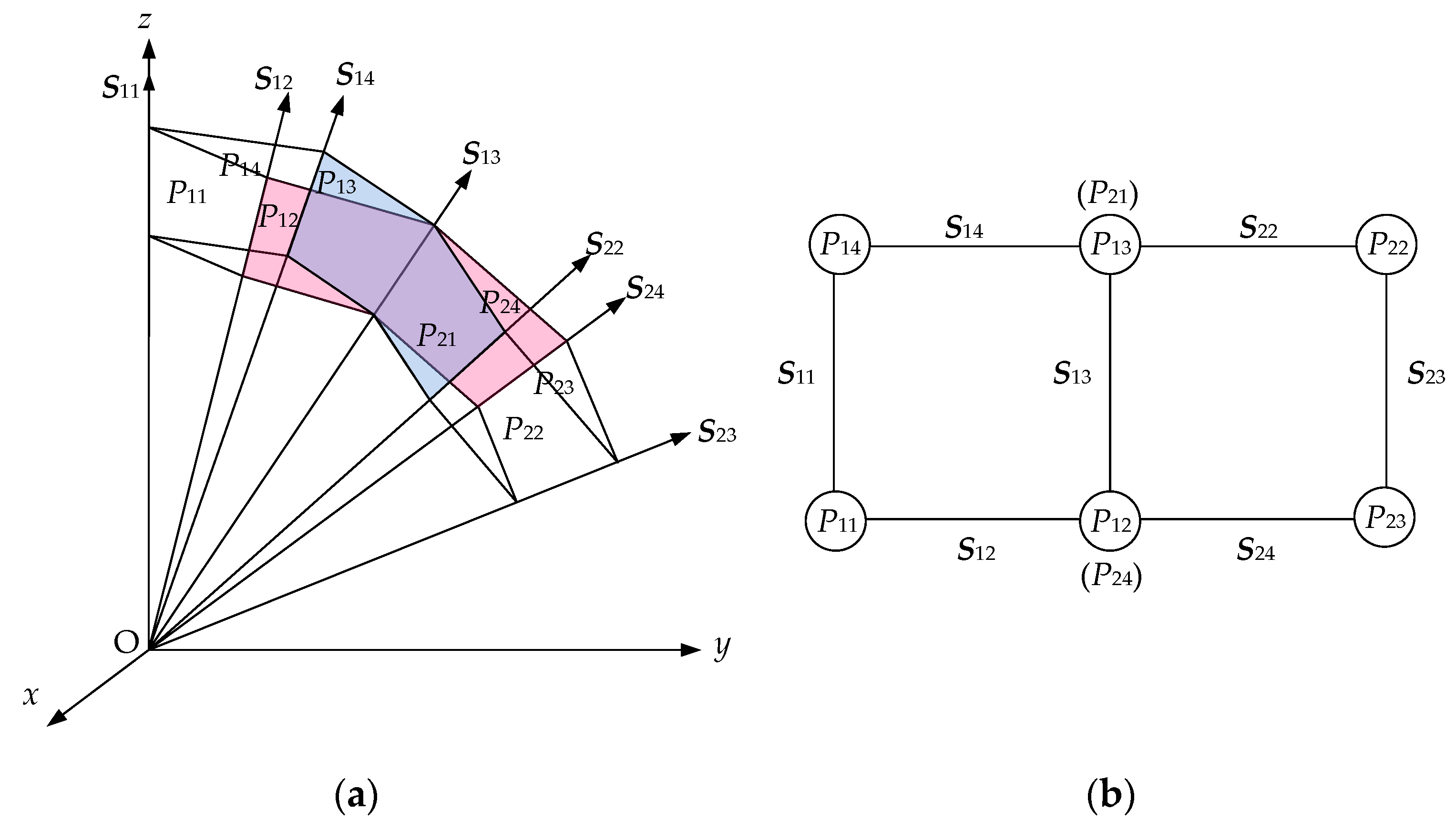
Mobility analysis of OM1_L1: (a) model of OM1_L1; (b) topology diagram.

Figure 12.
Mobility analysis of OM1_L2: (a) model of OM1_L2; (b) topology diagram.

Figure 13.
Topology diagrams of (a) OM3; (b) OM4.

Figure 14.
The stable configuration of the singly symmetric SOTC.

Figure 15.
The geometry of the doubly symmetric SOTC: (a) the geometric parameters of isosceles trapezoid panels; (b) the coordinate of doubly symmetric SOTC.
Figure 15.
The geometry of the doubly symmetric SOTC: (a) the geometric parameters of isosceles trapezoid panels; (b) the coordinate of doubly symmetric SOTC.

Figure 16.
The geometry of the singly symmetric SOTC: (a) the geometric parameters of two types of isosceles trapezoid panels; (b) the coordinate of doubly symmetric SOTC.
Figure 16.
The geometry of the singly symmetric SOTC: (a) the geometric parameters of two types of isosceles trapezoid panels; (b) the coordinate of doubly symmetric SOTC.

Figure 17.
Simulation of monolayer spherical deployable origami structure. (I) is the folded configuration of structure. (II,III) are the partially folded configuration of structure. (IV) is the desired configuration of structure with two sides of the structure touch each other at the bottom.
Figure 17.
Simulation of monolayer spherical deployable origami structure. (I) is the folded configuration of structure. (II,III) are the partially folded configuration of structure. (IV) is the desired configuration of structure with two sides of the structure touch each other at the bottom.

Figure 18.
Simulation of bilayer spherical deployable origami structure. (I) is the folded configuration of structure. (II,III) are the partially folded configuration of structure. (IV) is the desired configuration of structure with two sides of the structure touch each other at the bottom.
Figure 18.
Simulation of bilayer spherical deployable origami structure. (I) is the folded configuration of structure. (II,III) are the partially folded configuration of structure. (IV) is the desired configuration of structure with two sides of the structure touch each other at the bottom.

Figure 19.
The stable configuration of SDOS3 comprising the same doubly symmetric SOTC: (a) top view; (b) isometric view.
Figure 19.
The stable configuration of SDOS3 comprising the same doubly symmetric SOTC: (a) top view; (b) isometric view.

Figure 20.
The simulation of SDOS3 (Supplementary Materials) comprising singly symmetric SOTCs and MSDOS. (I) is the folded configuration of structure. (II,III) are the partially folded configuration of structure. (IV) is the desired configuration of structure with three branches of the structure touch each other at the bottom in state.

Figure 21.
The simulation of SDOS4 comprising singly symmetric SOTCs and MSDOS. (I) is the folded configuration of structure. (II,III) are the partially folded configuration of structure. (IV) is the desired configuration of structure with four branches of the structure touch each other at the bottom in state.

Disclaimer/Publisher’s Note: The statements, opinions and data contained in all publications are solely those of the individual author(s) and contributor(s) and not of MDPI and/or the editor(s). MDPI and/or the editor(s) disclaim responsibility for any injury to people or property resulting from any ideas, methods, instructions or products referred to in the content. |
© 2024 by the authors. Licensee MDPI, Basel, Switzerland. This article is an open access article distributed under the terms and conditions of the Creative Commons Attribution (CC BY) license (https://creativecommons.org/licenses/by/4.0/).
Share and Cite
MDPI and ACS Style
Qin, B.; Liu, S.; Wang, J.; Lyu, S. Deployable Structures Based on Non-Flat-Foldable and Non-Developable Origami with Constant Curvature. Actuators 2024, 13, 156. https://doi.org/10.3390/act13040156
AMA Style
Qin B, Liu S, Wang J, Lyu S. Deployable Structures Based on Non-Flat-Foldable and Non-Developable Origami with Constant Curvature. Actuators. 2024; 13(4):156. https://doi.org/10.3390/act13040156
Chicago/Turabian StyleQin, Bo, Shiwei Liu, Jianzhi Wang, and Shengnan Lyu. 2024. "Deployable Structures Based on Non-Flat-Foldable and Non-Developable Origami with Constant Curvature" Actuators 13, no. 4: 156. https://doi.org/10.3390/act13040156
Note that from the first issue of 2016, this journal uses article numbers instead of page numbers. See further details here.