Article

Development of an Automatic Air-Driven 3D-Printed Spinal Posture Corrector

1
Division of Mechanical Science and Technology, Graduate School of Science and Technology, Gunma University, Kiryu 376-8515, Japan
2
SEDS, Nazarbayev University, Nur Sultan 010000, Kazakhstan
*
Author to whom correspondence should be addressed.
Actuators 2022, 11(7), 184; https://doi.org/10.3390/act11070184
Submission received: 5 May 2022 / Revised: 30 June 2022 / Accepted: 1 July 2022 / Published: 4 July 2022
(This article belongs to the Section Actuators for Medical Instruments)

Abstract

:
Billions of people are using smartphones and computers with poor posture. A careless attitude towards spinal posture could be dangerous for long-term spinal health, leading eventually to curvature of the spine. Ignoring this fact and its treatment at the early stage will significantly deteriorate spinal health and force surgical intervention. Instead of developing an automated posture-correcting system, the existing research mostly focused on a posture-monitoring system to inform the users via a human interface, e.g., Bluetooth-based devices. Therefore, this paper proposes a novel posture-correction method to automatically prevent spinal disease by facilitating proper posture habits. Specifically, we develop a fluid-driven wearable posture corrector, whose skeleton can be fabricated simply using a 3D printer, to estimate angular posture deviation using sensors and provide appropriate assistance to correct the posture habit of the user. Mounted sensors provide the degree of postural bending, and a controller regulates the appropriate signals to provide a friendly pulling force as a reminder to the user through a fluid-driven actuator. The skeleton with a fluid-driven tool is designed to mimic the motion of the spinal posture by activating the actuator, which injects (or releases) the fluid into (or from) the skeleton frame and regulates forces to reduce the angular deviation of the skeleton. The 3D-printed skeleton with a flexible rubber tube has been experimentally evaluated to ensure proper actuating mechanism through the adjustment of air pressure. It is found that, by applying air pressure in the range of 0 to 101.4 kPa, the skeleton is pulled back approximately 1 N to 7 N forces, minimizing the angle up to 12.44 with respect to the initial steady stage, which leads to a maximum posture correction of 32.55% angle ( θ ) of poor posture. From the above experiments, we ensure the functionality of the proposed posture corrector in producing backward forces to correct the posture automatically.

1. Introduction

The correct systematic alignment of the bones and the proper distribution of muscles maintained through good posture are essential for a healthy life. Ignoring this fact could result in long-term consequences. Incorrect body positioning while working is a common problem among office workers. Research shows that pectoral kyphosis (lower-back pain) affects around 70% of computer users [1,2]. Billions of people around the world are using cell phones in poor posture as well [3]. Over 75% of people have experienced neck and shoulder pain at some point in their lives [4]. About three billion smartphone users worldwide suffer from neck and shoulder pain due to poor neck posture [5].
Spinal disorder can be treated surgically, medically, or through exercises. The non-surgical method involves a very simple physical exercise such as stretching to improve the strength of the spine [6]. Most people straighten up their bodies by jogging and walking, but sometimes they forget to sit properly while studying or working [4]. According to Harvard Medical School, a simple way to avoid spinal disorders is to pay close attention to the body posture every day [7]. Out of nonsurgical exercises, the surgical method covers spine stabilization and deformation correction, and screw implantation [8,9]. Although treatments proved its effectiveness, they require a long healing period, and sometimes risky surgery is unavoidable. Nevertheless, unexpected changes in the spine could be avoided at the initial stage of deformation.
Human posture monitoring and correcting disorders are highlighted by many researchers [3,4,5,7,10,11,12]. In [3,10,13,14], wireless technology using posture and strain sensors was proposed to detect poor posture according to the threshold value and alert the user via smartphone. Some researchers used a flex sensor, instead of posture and strain sensors, to detect spinal bending. A flex sensor can also assess the user’s actual positions, such as sitting, standing, or walking, based on weight records, and provides email report feedback by its centralized server [10]. Instead of a vibration motor, some researchers [11] used a buzzer controller in a shirt to be worn and alert the user. The controller sends poor-posture information to the buzzer and informs the users. After receiving an alert, the user must correct themselves from the bad posture; otherwise, the attached DC gear motor on a flexible belt will be activated and lifts back the slouching user to its normal position.
In [14], the authors proposed a sensor-based inertial measurement unit (IMU) monitoring system, to check angular deviation that leads to musculoskeletal disorder. Noticeably, the sensor can communicate with many devices such as smartphones, tablets, and laptops via the Bluetooth low energy protocol. An experimental study was conducted [10,15] with the placement of accelerometers at the back of a user, to build a 3D shape of the body posture. Whenever it recognizes the desired shape, the user receives feedback through a vibration motor. The accelerometer, gyroscope and IMU sensors are also used [7,11] for posture monitoring instantly with the assistance of an independent device. An algorithm compares the data received immediately with the previously calibrated to verify whether the data points fall within the desired region or not. If not, then the posture is considered incorrect.
In addition to flexible and inertial sensors, researchers also proposed pressure, inductive, and optical-fiber sensors for posture monitoring [16]. Study [17] explained the importance of developing a low-cost anti-hunchback device, which is claimed as comfortable, affordable, and wearable but not that easy to transport. With mounted accelerometers and a gyroscope, a garment was developed to control trunk posture in [18]. It can check the curvature of the spine and provides instant feedback for preventing lumbar spinal disorder, but the garment is unable to prevent the postural disorder automatically.
In [19], the author proposed a posture assessment system based on three magneto-inertial measurement units (MIMU), which later compared with motion capture systems (MoCaps). MIMUs are placed on thoracic vertebra (T3, T12) and sacral vertebra (S1). The system assessed the thoracic kyphosis (difference in slope between T3 and T12) and lumbar lordosis (between T12 and S1) angles. The comparison results for thoracic kyphosis and lumbar lordosis shows a maximum root mean square error (RMSE) of 5.6 angle. Although the solution claimed to be affordable and simple to set up in unstructured situation, inaccurate placement of the MIMU sensors produces erroneous measurements, which will emphasises the need for the vest to have proper placement.
The literature indicates that researchers have proposed posture-monitoring systems in several ways. In some cases, a DC motor is used, while others used a buzzer to alert the users. In addition to buzzer and motor usage, some others use a mobile application and Bluetooth technology to inform the user. Mostly, the authors used flexible sensors and/or inertial sensors to obtain bending information, while another uses inductive sensors as well. An anti-hunchback device was also proposed to prevent postural disorders and head-and-neck pain. A different approach is also taken by designing a garment to be worn and which notifies about improper posture. All these methods basically proposed some sort of monitoring system only, rather than presenting an automatic postural-correction system. Therefore, the investigation of the posture-correction system demonstrates the importance of working in this field. In turn, designing a posture-correction system is an interesting field of research in biomedical engineering.
This paper proposed a novel idea of preventing pectoral kyphosis disease and poor posture without interrupting users’ work. We specifically propose a 3D-printed fluid-driven wearable posture corrector that obtains the angular posture deviation using sensors and provides appropriate assistance to correct the posture habit of the user. Sensors are mounted to provide an indication of postural bending, and the controller sets appropriate signals to remind the user through a fluid-driven actuator. The controller detects continuous changes in spinal posture with a very small change in action. The control structure responds only to constant misalignment and ignores minor movements. The fluid-driven skeleton is intended to replicate the motion of spinal posture by activating the actuator, which injects (or releases) fluid into (or from) the skeleton frame and imposes force to lower the angular deviation of the skeleton. The most important mechanism of the pressure actuator is experimentally evaluated with the printed skeleton and an additional flexible rubber tube to ensure its functional characteristics by adjusting the air pressure. It is observed that the more air pressure is applied, the more the skeleton can pull the force to reduce the angular deviation. Moreover, a new manufacturing technique in actuator design allows for personalized fabrication at a lower cost, and fused deposition modeling (FDM) technology can ensure the unique spine shape of a patient. Thus, the proposed idea is suitable to automatically prevent pectoral kyphosis disease and poor posture.
The paper is organized as follows: Section 1 elaborates the introduction with the state-of-the-art research. Section 2 illustrates the development of the posture corrector scheme. Results and discussions are explained in Section 3 and Section 4, respectively. Finally, the paper concludes with Section 5.

2. Development of Posture Corrector Scheme

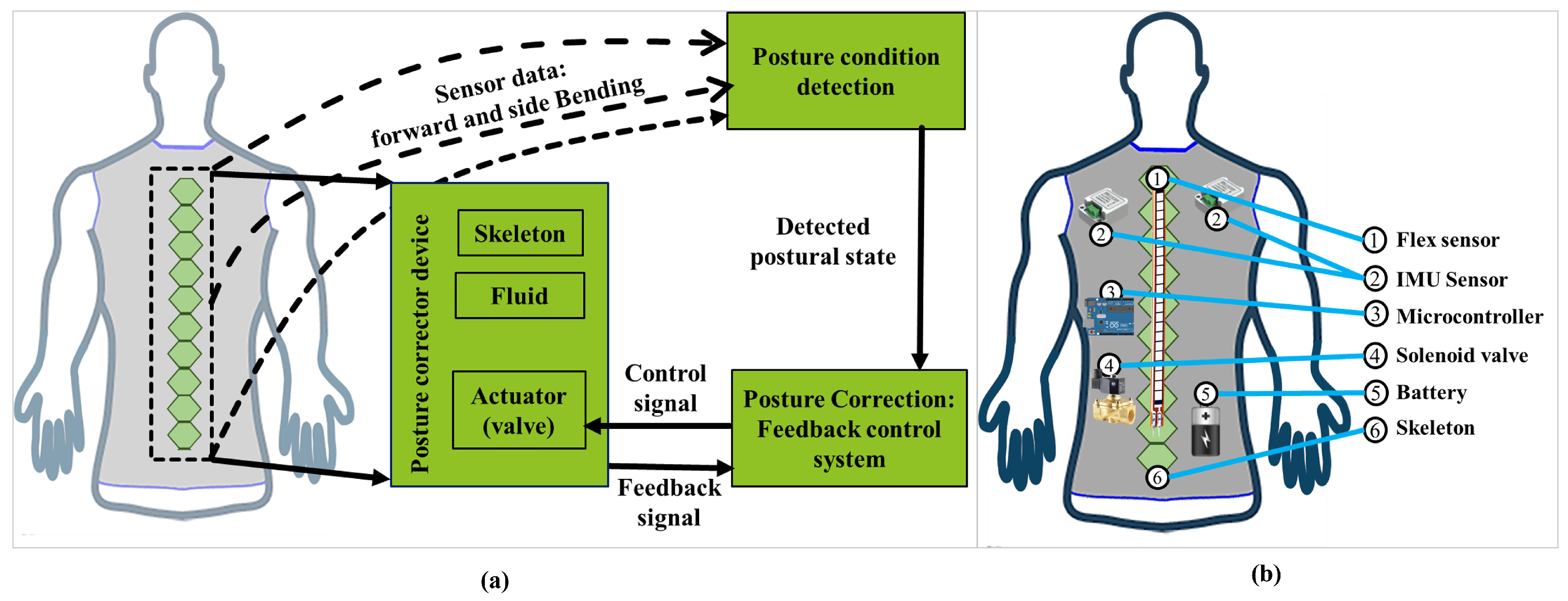
2.1. Overview of the Proposed Posture Corrector

A fluid-driven wearable posture-correction system was designed and developed, which is described in this section. As shown in Figure 1a, the proposed system consisted of a sensor-based posture-detection unit, a 3D-printed skeleton with fluid-based actuating mechanism, and a posture-correction controller. Figure 1b shows anatomical location of individual elements of the proposed wearable system. The flex sensor is mainly placed along with the spine, whereas IMUs are in the upper thoracic region. The rest of the elements, i.e., controller, valve and battery, are placed in lower thoracic and lumber region of a user.
For this development, we considered existing sensing technologies to obtain the relevant information by introducing a better approximation technique. The design and development of the skeleton and its working mechanism is the key part in this system for creating force on spine with respect to applied pressure, which is the main concern of this paper. After the development of the skeleton, the sensors were mounted on it. Whenever the skeleton moves to any certain angle (e.g., due to body flexion in sagittal plane), the sensor detects and sends to the controller that injects air pressure, if needed. The skeleton needs to create a backward force (body extension in sagittal plane) that applies air pressure through the valve to reduce skeleton angular deviation, which is experimentally evaluated in this paper.

2.2. Sensors

We propose a sensor-based investigation for the automatic posture corrector. The sensors are considered to receive continuous change in spinal posture and send it to the controller in a meaningful way, so that it can be used for detecting only the critical bending ( θ 15 ). Two types of sensors were mainly used for this proposed design, the flex and IMU sensors. A flex sensor was used to obtain the bending degree usually in sagittal plane (forward direction), whereas an IMU sensor was used to detect the curvature of the shoulder in the right and left direction [6].
The flex sensors are made of materials that are malleable to some degree without influencing their properties. Due to such properties of flexible piezoelectric material, its resistance varies with bending angle. As is depicted in the line graph and human postural states, the higher the bending level, the higher the resistance value (Figure 1a,b). This sensor is distinguished by its lower cost, longer life, and lower sensitivity to detecting even a small bending degree of the spine [16].
The characteristics of the flex sensor are nonlinear. For the posture-correction controller, any sensed bending information must be interpreted precisely, despite such non-linearity. Therefore, from raw experimental observation data [12], a polynomial approximation was considered to establish the continuous relationship of the resistance R F l e x of the flex sensor with respect to the bending angle. The polynomial function of the continuous resistance change R F l e x (in order of K Ω ) with respect to the bending angle θ is given as
R F l e x ( θ ) = 2.01 × 10 6 θ 4 3.10 × 10 4 θ 3 + 1.30 × 10 3 θ 2 + 1.87 θ + 10.11
In case of normal standing, i.e., with 0 bending position in sagittal plane by sensor/human spine in Figure 2b, the bending resistance R F l e x ( 0 ) was measured as 10 K Ω . From (1), the resistance value can be calculated at any particular angle, for example, at 30 resistance is R F l e x ( 30 ) = 60.73 K Ω . Whenever a user bends forward at a certain angle for a certain period, the sensor detects the bending degree and sends it to the controller for further processing.
IMU sensors have attracted interest in medical, aerospace and other engineering fields because of its small size, high portability, low cost, and measurement accuracy, which enables them to be inserted directly into people’s clothes as well [1,16]. It detects the exact position of shoulder posture of right and left lateral flexion in space, as shown in Figure 3a, and sends real-time data to the controller, which helps to monitor the detected values in real-time [1,11,20].
Smartphone users generally spend an average of 2 to 4 h a day for browsing, reading, and texting. Collectively, the spent hours become 700 to 1400 h in a year [5]. Mostly, they tend to tilt their head forward (flexion in sagittal plane), however, the computer user bends their spine forward (flexion in sagittal plane) while using it. In each case, the human body experiences a particular weight on the spine [3,4,11]. It gradually increases with the increase in flexing the head forward. Based on the experimental data presented in the research [3], a polynomial approximation was considered to establish a continuous relationship function of the change in the imposed weight ( W k g ) on the neck with respect to the degree of bending ( θ ), which is depicted in Figure 3b, which is given as
W k g = 6.03 × 10 5 θ 3 7.8 × 10 3 θ 2 + 0.62 θ + 4.45
It is found from (2) that, when naturally standing (0 bending), the imposed weight is around 4.5 kg. Similarly, for instance, at 30 , weight imposed is 18 kg.

2.3. Design of Skeleton

Our proposed design and fluid-driven 3D-printed skeleton architecture is based on origami-inspired artificial muscle [21]. With the origami shape, the fluid-flow can be efficient in terms of the extension and contraction of the skeleton. In addition, the fabrication process is also easy, with a variety of materials at very low costs. The key element of our proposed system is the actuating skeleton, which needs to be designed with the customized body structure of a user. Most importantly, the skeleton should be light and flexible enough for user comfort and, at the same time, tough enough to apply pulling force to the user. In addition, the skeleton must play dual roles by being mounted with the sensor for perceiving posture information and applying force on the backbone concerning the applied pressure through actuating mechanism. Therefore, materials for 3D printing should be chosen carefully to realize the skeleton’s desired characteristics. At first, we used different materials for printing the skeleton, including PLA, ABS, and flex materials, to check the skeleton’s flexibility and ability to generate pulling force. As PLA is a stiff plastic and brittle, it has a low flexural strength compared to other materials such as ABS and flex. Although ABS is less rigid than PLA, it requires more effort to print than PLA because it is heat-resistant and prone to warping. Therefore, the flex material was eventually chosen as the printing material to overcome those problems. The materials are listed in Table 1.
The 3D shape of the skeleton was designed in SOLIDWORKS software, as shown in Figure 4. It mainly consists of two components, which are a flexible solid skeleton (Figure 4a) and a flexible skeleton frame (Figure 4b), where the frame cap was designed separately (Figure 4c). As it is designed and printed separately, gluing, pressing, or welding could be used to seal the cap on the skeleton frame.
Naturally, the human spine is not straight but curved. Therefore, multiple small skeleton blocks can fit properly within the spine to mimic spinal movement. The number of skeleton blocks mainly depends on the user’s spinal height. According to the Japan demography report of 2020, the average height of Japanese men is 170.7 cm (5′6″) and for women 157.8 cm (5′1″) [22]. Considering the average height of a user (man), the mean total spinal height is 56.94 cm observed in [23]. By considering the above measurement, the proposed design of the skeleton was printed with the same height (56 cm) and comprised of 14 blocks, where each of them were 4 cm. Nevertheless, this skeleton block can be customized to fit even smaller or taller people by changing the number of blocks according to their height.
The physical dimensions of posture corrector device has been presented in Table 2. As it is observed, each skeleton block has a height of 40 mm, which is the same as its frame. Inversely, the width of each block is 50 mm, but its frame has 60 mm width to place the skeleton. This 10 mm extra space will be used for fluid to pass through. Lastly, the skeleton frame cap was designed with a similar dimension to skeleton frame (open spaces only) to be mounted on top of it. The entire design (Figure 4a–c) would be attached mainly at the back of a user in a vest. Figure 4d shows a prototype of a vest, which can be implemented in future research work.

2.4. Fluid-Driven Actuating Mechanism

The general scenario of the actuating mechanism with different posture states 1–4 is shown in Figure 5a–d. Posture state-1 (Figure 5a) shows the proper posture of a user while normally standing ( θ S t a t e - 1 = 0 ). As there is no air pressure injected in state-1, the pressures inside and outside are the same ( P in = P out ).
When the user tends to tilt his head forward in state-2 (Figure 5b), the sensor detects it as a critical bending. Thereupon, the actuator will start to inject fluid (air) inside the skeleton frame which leads to a pressure difference between inside and outside. Therefore, the pressure inside increases more than the pressure outside ( P i n >> P o u t ). This high pressure ( P i n ) applies force to the spine, consequently changing the angle of bending of the body posture. The change in bending angle gradually increases due to applying higher pressure. As a result, the bent skeleton slowly straightened in posture state-3 (Figure 5c). Thus, the angle θ S t a t e - 3 becomes lower than θ S t a t e - 2 ( θ S t a t e - 3 < θ S t a t e - 2 ).
Continuing the pressure to the skeleton leads to a normal postural state once again, illustrated in posture state-4 (Figure 5d). Once the postural state is corrected to that desired, the injected air pressure will be removed from the skeleton frame, and, as a result, the air pressure inside and outside will be the same again ( P i n = P o u t ).

2.5. Design of Controller for Posture Corrector

The overview of the control system for the actuator is shown in Figure 6. For a given reference θ R , the angle difference signal is used to decide whether to increase or decrease the skeleton pressure, according to some given preferences and restrictions related to maximum or minimum limits of skeleton pressure and flow rates of the fluid. For this purpose, the sensor obtains the angular displacement ( θ ) and sends the signal to the controller. Specifically, whenever the skeleton bends in the sagittal plane and makes a certain angle of 15 or more, then the sensor receives the output of the critical angle, which then feedbacks to the controller.
The control system works under two conditions. Firstly, the users should put on the device on their bodies. Next, the system takes a few seconds to complete the initial calibration. When the system is initialized, the user should be in the reference position. When the user maintains good posture, the system captures the readings of the flex sensor and sets the position as the reference point. Normally, using the first three values recorded by the sensor, a nominal reference value is calculated. The average of these three values is taken as the threshold. A tolerance of 3–5% is accepted to determine whether posture is good or bad. Secondly, the actuator is activated when the critical bending ( θ ) remains constant for 15 s at an angle of 15 in sagittal position. A control flowchart of the posture corrector is presented in Figure 7 to show the step-by-step actuating mechanism of posture corrector.

3. Experimental Results

Various technologies (machining, folding, casting) and materials can be used to fabricate this skeleton. The manufacturing process of this design allows the user to fabricate a unique and customized skeleton for any individual. Additionally, the fabrication of a large number of skeleton blocks can increase the quality and efficiency of the design. The joining of each block increases the strength and reliability of the skeleton as well.
The skeleton prototype, along with its frame, was printed using an FDM printer with the chosen flex material. The customized 800 mm large 3D printer (Figure 8a) made the prototype unique and accurate compared to other available 3D printers on the market. The skeleton, its frame, and an additional rubber tube are shown in Figure 8b. Each of them is 56 cm in height. Although the skeleton blocks are designed separately (Figure 4a), it was printed as an entire device, as shown in Figure 8a. The printed skeleton weighs 250 gm (2.5 N).
An experimental study was conducted as a proof-of-concept by observing the working principle and characteristics of the proposed posture corrector, specifically the actuator part. At first, with manual inspections, it was found that the flexible skeleton is easily bent, but its elastic property helps it to return to its original straight position effortlessly, i.e., without any fluid pressure, the skeleton itself shows elasticity behavior. For simplicity in the experimental evaluation of the working mechanism, instead of a fully concealed skeleton frame, we used an auxiliary rubber tube with a manual air-injecting mechanism, shown in Figure 8c, where the rubber tube is well-mounted on the skeleton with a couple of zip-ties. Although the proposed design used a cap to cover the skeleton frame, for convenience in the experiment, a separate cover was not taken into consideration as the rubber tube plays both the role of an air container and a cover.
In fact, the rubber tube makes a curve shape while fully pumped, but, noticeably, whenever it is placed inside the skeleton frame, it becomes completely straight, as seen in Figure 8b. As the tube is attached with a couple of zips, it cannot move on any side, while the skeleton itself prevents the creation of a curve shape, as it is originally a flat shape.
The initial condition of the skeleton (human spine) without any load is shown in Figure 9a. For the main experiment, almost half of the 56 cm long skeleton was attached with a heavy iron bar to keep that part fixed and the rest was left open to check the angular deviation (Figure 9b,c). A cotton rope was used to pull the skeleton with some particular forces. Specifically, one end of the cotton rope was attached to the skeleton, while the other end with a 100–700 gm (≈1–7 N) weight bar in a commonly marked place. Each time the weight bar was moved forward at least 5 cm from the marked place while the air pressure was applied, only then were the pressure (kPa) and changed distance (d c m ) (for finding the angular deviation, θ 1 and θ 2 ) taken into account. In general, the air pressure within the tube gradually increased from 0 to 101.4 kPa. Upon application of the pressure, the skeleton was found to be pulled back by a particular force in the range of approximately 1–7 N.
From Figure 9b,c, it is observed that the skeleton in Figure 9c ( θ 2 ) poses a lower angle than in Figure 9b ( θ 1 ) due to the difference in applied force (approximately 6 N and 4 N, respectively). As the applied pressure in the second case (Figure 9c) is higher than the first case (Figure 9b), angular deviation in the second case becomes lower than the first case.

4. Discussion

The experiment was conducted numerous times (Table A1, Table A2 and Table A3) to obtain meaningful values of its mechanism consistency and result accuracy of the angular deviation ( θ ), pressure (kPa), and force (N). Each time, the skeleton successfully pulled the applied force and reduced the angle significantly (by over 12 ) from its initial stage. Out of 70 samples, one of the samples of pressure was measured as 95.15 kPa (13.8 psi) at 6 N pulling force (Figure 9d). After measuring all the samples, the average of them makes us draw the following relations.

4.1. Force vs. Pressure

From the experiment, it becomes apparent that, on average, 1 N force can be pulled back by applying 44.33 kPa air pressure (Figure 10). Similarly, for the 2 N force, it takes 59.22 kPa. Like the first two, the rest (≈3–7 N) of the experiments were also conducted with the increased air pressure (≈68–101 kPa, respectively). As observed, both the X and Y scales showed an upward trend to maintain a healthy postural state.

4.2. Force vs. Angular Deviation

At 0 N force, the angular deflection was recorded as 33 , which marginally reduced for the rest of the angular positions (Figure 11). Specifically, at 1 N, the force pulled the skeleton back and reduced the angle by 3.3 . It then reached a minimum deviation of 20.56 at 7 N. The trend line proves that, whenever a user experiences a spinal bending with any certain force, the actuator will apply air pressure to the skeleton device. As more air goes inside the skeleton frame, more air pressure will be applied to the spine. Consequently, the air pressure starts pulling the device and pulling back the user. The steady increase in air pressure continues to reduce the postural angular deviation, which eventually leads to a corrected posture automatically.

4.3. Pressure vs. Angular Deviation

Initially, there is no air pressure imposed on the skeleton, so the maximum skeleton angle is recorded as 33 in Figure 12. Over the following different pressure levels, the angular deviation gradually dropped below 13 from its initial state, whereas the pressure follows the opposite trend, to reach 101.4 kPa pressure at the lowest recorded angle of 20.56 . Therefore, it is observed that by slowly increasing the air pressure the angular deviation decreases gradually, which will assist the user to correct the posture.

5. Conclusions

This article has proposed a 3D-printed fluid-driven wearable posture corrector to encourage proper posture habits and prevent spinal disorders. In the posture-corrector skeleton, the mounted sensors provide posture-bending information to the controller, which takes the necessary decision to drive the fluid-driven actuator. The skeleton with fluid-driven actuator was primarily designed to mimic the spinal movements by adjusting fluid pressure, i.e., inject/release fluid into/from the skeleton frame, which eventually helps to minimize the angular deviation of the skeleton. The most important mechanism of the pressure actuator was experimentally evaluated by combining the lab-fabricated skeleton with a flexible rubber tube, where the air pressure inside the tube was gradually increased from 0 to 101.4 kPa. Upon application of pressure, the skeleton was found to be pulled back by a particular force in the range of approximately 1–7 N. Noticeably, the more air pressure was applied, the more the skeleton can pull the force and reduce the angular deviation. The measurement was conducted numerous times to ensure mechanism consistency and result accuracy. Each time the skeleton successfully pulled the applied force and reduced the angle significantly from its initial stage, that led to a 32.55% poor-posture correction in the experiment. Measurement results confirmed the functionality of the automatic posture corrector, which can be enhanced to realize a wearable, fully functional, 3D-printed fluid-driven posture corrector for preventing postural disorders.

Author Contributions

Conceptualization, G.M.A., M.H.A. and M.A.S.K.; methodology, G.M.A., M.H.A. and M.A.S.K.; validation, G.M.A. and M.H.A.; formal analysis, G.M.A., M.H.A. and M.A.S.K.; supervision, M.A.S.K. and K.Y.; project administration, G.M.A. and M.H.A.; writing—original draft preparation, G.M.A., M.H.A., K.H. and M.A.S.K.; writing—review and editing, G.M.A., M.H.A., K.H., M.A.S.K. and K.Y.; All authors have read and agreed to the published version of the manuscript.

Funding

This research received no external funding.

Institutional Review Board Statement

Not applicable.

Data Availability Statement

Not applicable.

Acknowledgments

This research is supported in part by JSPS Grant-in-Aids for Scientific Research (C) 21K03930.

Conflicts of Interest

The authors declare no conflict of interest. The funder had no role in the design of the study; in the collection, analyses, or interpretation of data; in the writing of the manuscript, or in the decision to publish the results.

Appendix A

Appendix A.1. Experimental Data

The measurement was conducted more than 70 times to ensure the consistency of the mechanism and precision of the results, as shown in the following Table A1, Table A2 and Table A3. Each time, the skeleton successfully pulled the applied force and reduced the angle significantly from its initial stage. The angular displacement ( θ ) is considered as the position of the skeleton when the load was added to the skeleton (Figure 9b) but the pressure (kPa) is yet to be applied; position (of load) was fixed for the whole experiment. Later, the retraction angle ( θ ) was taken into account after applying the air pressure, to distinguish between both of them. Finally, the average deviation results shows that (Table A2 and Table A3) the deviation increased with respect to its initial bending position (30.5 ), i.e., by applying pressure over 100 kPa, the body load of 7 N force can be pulled back with the angle from 30.5 to 20.56 , which leads to a maximum posture correction of 32.55% (Table A3) angle ( θ ) of poor posture.
Table A1. Measured pressure (kPa) with respect to the applied load (N) by body on skeleton.
≈Applied Load by Body on SkeletonWith 1 N Load (kPa)With 2 N Load (kPa)With 3 N Load (kPa)With 4 N Load (kPa)With 5 N Load (kPa)With 6 N Load (kPa)With 7 N Load (kPa)
Trial no. 156.4066.7074.8780.6688.3296.67105.75
255.4256.5471.2276.2483.6692.2398.35
337.5056.4769.6679.3288.1882.22100.17
439.5063.7267.3472.2678.2996.58103.85
551.7064.4373.7177.6186.1090.24101.60
646.1357.8361.4779.9882.9394.5997.95
740.5561.1559.5677.2987.2984.4198.73
841.8852.1363.8677.8181.5589.7096.65
944.0260.8868.5675.3577.8485.18104.16
 1042.2352.4365.5378.4686.2487.23106.82
 Average44.3359.2368.4775.5084.0489.90101.4
Table A2. Measured angle ( θ ) and deviation (%) with respect to 1 N–2 N applied load by body on skeleton.
≈1 N Applied Load by Body on SkeletonAngular Displacement ( θ ) Angular Retraction ( θ ) Deviation ( % ) Average
Trial no. 130.5028.984.982.61%
230.5029.503.28
330.5030.200.98
430.5029.892.00
530.5029.622.89
630.5029.692.66
730.5029.852.13
830.5029.812.26
930.5029.732.52
 1030.5029.772.39
≈2N Applied LoadAngular Displacement ( θ ) Angular Retraction ( θ ) Deviation ( % ) Average
Trial no. 130.5027.759.035.59%
230.5028.925.18
330.5029.433.51
430.5028.566.37
530.5027.958.37
630.5028.815.55
730.5028.616.21
830.5029.712.60
930.5028.765.71
 1030.5029.483.34
Table A3. Measured angle ( θ ) and deviation (%) with respect to 3 N–7 N applied load by body on skeleton.
≈3N Applied Load by Body on SkeletonAngular Displacement ( θ ) Angular Retraction ( θ ) Deviation ( % ) Average
Trial no. 130.5027.3810.237.82%
230.5027.818.82
330.5027.878.62
430.5028.177.64
530.5027.759.02
630.5028.586.30
730.5029.114.57
830.5028.367.02
930.5027.958.36
 1030.5028.187.61
≈4N Applied LoadAngular Displacement ( θ ) Angular Retraction ( θ ) Deviation ( % ) Average
Trial no. 130.5026.3313.6710.96%
230.5027.679.28
330.5026.6312.69
430.5028.217.50
530.5026.8611.93
630.5026.6312.69
730.5027.559.67
830.5026.9211.74
930.5028.028.15
 1030.5026.7712.23
≈5N Applied LoadAngular Displacement ( θ ) Angular Retraction ( θ ) Deviation ( % ) Average
Trial no. 130.5023.7722.0718.40%
230.5025.3117.02
330.5023.9421.51
430.5025.6915.77
530.5024.8518.52
630.5025.4716.49
730.5024.2720.43
830.5025.5816.13
930.5025.6915.77
 1030.5024.3120.30
≈6N Applied LoadAngular Displacement ( θ ) Angular Retraction ( θ ) Deviation ( % ) Average
Trial no. 130.5021.3330.0726.12%
230.5022.1827.28
330.5023.6522.47
430.5021.3729.93
530.5022.6325.80
630.5021.5729.28
730.5023.2923.65
830.5022.9424.79
930.5023.2323.85
 1030.5023.1524.10
≈7N Applied LoadAngular Displacement ( θ ) Angular Retraction ( θ ) Deviation ( % ) Average
Trial no. 130.5019.5935.7932.55%
230.5021.3030.16
330.5020.5332.69
430.5019.9834.48
530.5020.2133.74
630.5021.9428.07
730.5020.9531.31
830.5021.9428.07
930.5019.8534.92
 1030.5019.4336.30
Each of Table A2 and Table A3 is associated with the scatter plots of the observed data points arranged in descending order, as shown in Figure A1 and Figure A2, respectively. Initially, the pressure curve has little fluctuation due to the low applied load. As the load is increased, the pressure curve becomes closer to a flat line. Although it is becoming close to flat, the pressure increased in every step due to the higher load imposed on the skeleton.
Figure A1. The observed data, showing the co-relation between pressure and angle at 1 N–2 N load.
Actuators 11 00184 g0a1
Figure A2. The observed data, showing the co-relation between pressure and angle at 3 N–7 N load.
Actuators 11 00184 g0a2

References

  1. Asadullah, G.M.; Sabyrov, N.; Kamal, M.A.S.; Ali, M.H. Design of a fluid-driven 3d printed spinal posture corrector. Mater. Today Proc. 2021, 44, 1555–1559. [Google Scholar] [CrossRef]
  2. Fathi, A. Prevalence rate of postural damages, disorders and anomalies among computer users. Phys. Treat. Specif. Phys. Ther. J. 2016, 1, 59–65. [Google Scholar] [CrossRef] [Green Version]
  3. Hansraj, K.K. Assessment of stresses in the cervical spine caused by posture and position of the head. Surg. Technol. Int. 2014, 25, 277–279. [Google Scholar] [PubMed]
  4. Liao, D.-Y. Design of a secure, biofeedback, head-and-neck posture correction system. In Proceedings of the IEEE First International Conference on Connected Health: Applications, Systems and Engineering Technologies (CHASE), Washington, DC, USA, 27–29 June 2016; pp. 119–124. [Google Scholar]
  5. Lawanont, W.; Mongkolnam, P.; Nukoolkit, C. Smartphone posture monitoring system to prevent unhealthy neck postures. In Proceedings of the 12th International Joint Conference on Computer Science and Software Engineering (JCSSE), Songkhla, Thailand, 22–24 July 2015; pp. 331–336. [Google Scholar]
  6. Sardini, E. Wireless wearable t-shirt for posture monitoring during rehabilitation exercises. IEEE Trans. Instrum. Meas. 2014, 64, 439–448. [Google Scholar] [CrossRef]
  7. Ribeiro, P. Spine Cop: Posture Correction Monitor and Assistant. Sensors 2020, 20, 5376. [Google Scholar] [CrossRef] [PubMed]
  8. Yaman, O. Kyphosis and review of the literature. Turk. Neurosurg. 2014, 24, 455–465. [Google Scholar] [CrossRef] [Green Version]
  9. Finocchiaro, F.M. Treatment of kyphotic deformities in adults: Our experience. Eur. Spine J. 2012, 21, 100–107. [Google Scholar] [CrossRef] [PubMed] [Green Version]
  10. Hermanis, A.; Nesenbergs, K. Grid shaped accelerometer network for surface shape recognition. In Proceedings of the 13th Biennial Baltic Electronics Conference, Tallinn, Estonia, 3–5 October 2012; pp. 203–206. [Google Scholar]
  11. Kumar, A.; Aravindan, M.C. Posturector-the posture corrector. Int. J. Innov. Sci. Res. Technol. 2017, 2, 70–74. [Google Scholar]
  12. Al-Rahayfeh, A.; Faezipour, M. Application of head flexion detection for enhancing eye gaze direction classification. In Proceedings of the 36th Annual International Conference of the IEEE Engineering in Medicine and Biology Society, Chicago, IL, USA, 26–30 August 2014; pp. 966–969. [Google Scholar]
  13. El-Sayed, B.; Farra, N.; Moacdieh, N.; Hajj, H.; Haidar, R.; Hajj, Z. A novel mobile wireless sensing system for realtime monitoring of posture and spine stress. In Proceedings of the 1st Middle East Conference on Biomedical Engineering, Sharjah, United Arab Emirates, 21–24 February 2011; pp. 428–431. [Google Scholar]
  14. Petropoulos, A.; Sikeridis, D.; Antonakopoulos, T. SPoMo: IMU-based real-time sitting posture monitoring. In Proceedings of the IEEE 7th International Conference on Consumer Electronics-Berlin (ICCE-Berlin), Berlin, Germany, 3–6 September 2017; pp. 5–9. [Google Scholar]
  15. Alsuwaidi, A. Wearable posture monitoring system with vibration feedback. arXiv 2018, arXiv:1810.00189. [Google Scholar]
  16. Tlili, F.; Haddad, R.; Ouakrim, Y.; Bouallegue, R.; Mezghani, N. A survey on sitting posture monitoring systems. In Proceedings of the 9th International Symposium on Signal, Image, Video and Communications (ISIVC), Rabat, Morocco, 27–30 November 2018; pp. 185–190. [Google Scholar]
  17. Maidin, N.A. A Prototype development of anti-hunchback device. J. Mech. Eng. 2018, 15, 192–209. [Google Scholar]
  18. Wong, W.Y. Smart garment for trunk posture monitoring: A preliminary study. Scoliosis 2008, 3, 7. [Google Scholar] [CrossRef] [PubMed] [Green Version]
  19. Paloschi, D. Validation and Assessment of a Posture Measurement System with Magneto-Inertial Measurement Units. Sensors 2021, 21, 6610. [Google Scholar] [CrossRef] [PubMed]
  20. Simpson, L. The role of wearables in spinal posture analysis: A systematic review. BMC Musculoskelet. Disord. 2019, 20, 55. [Google Scholar] [CrossRef] [PubMed]
  21. Li, S.; Vogt, D.M.; Rus, D.; Wood, R.J. Fluid-driven origami-inspired artificial muscles. Proc. Natl. Acad. Sci. USA 2017, 114, 13132–13137. [Google Scholar] [CrossRef] [PubMed] [Green Version]
  22. Japan Demographics: What’s the Average Life Expectancy, Height, and Monthly Income? Available online: Https://livejapan.com/en/in-tokyo/in-pref-tokyo/in-shinjuku/article-a0000962 (accessed on 16 September 2020).
  23. Busscher, I. Comparative anatomical dimensions of the complete human and porcine spine. Eur. Spine J. 2010, 19, 1104–1114. [Google Scholar] [CrossRef] [PubMed] [Green Version]
Figure 1. Overview of the proposed posture corrector (a) framework and (b) component positioning.
Actuators 11 00184 g001
Figure 2. Characteristics of a flex sensor (a) resistance versus bending angle and (b) posture states in sagittal plane versus the resistance in five different bending cases R 5 > R 4 > R 3 > R 2 > R 1 .
Actuators 11 00184 g002
Figure 3. Estimated characteristics of the IMU sensor (a) lateral flexion of human posture and (b) relationship between the head flexion angle in sagittal plane ( θ ) and weight (kg) imposed on spine.
Actuators 11 00184 g003
Figure 4. Design of the posture corrector (a) skeleton blocks, (b) skeleton frame, (c) skeleton frame cap, and (d) an image of designed posture corrector placed in a vest.
Actuators 11 00184 g004
Figure 5. Illustration of the operating principle with the posture states (a) normal posture state, (b) bent spinal state with injected fluid, (c) recovery of spinal deviation as a result of fluid injection, (d) returning to original spinal state (fluid removed), and (e) skeleton side view.
Actuators 11 00184 g005
Figure 6. Feedback control system.
Actuators 11 00184 g006
Figure 7. The control flowchart of the posture corrector.
Actuators 11 00184 g007
Figure 8. Printed posture corrector (a) FDM 3D-printing environment, (b) skeleton, its frame and rubber tube, and (c) pumped rubber tube placed on the skeleton.
Actuators 11 00184 g008
Figure 9. Experimented posture corrector, (a) spinal state at normal standing, (b) skeleton pulling with 4N force, (c) skeleton pulling with 6N force, and (d) pressure recorded at 6N force.
Actuators 11 00184 g009
Figure 10. Force versus air pressure obtained from the experiments.
Actuators 11 00184 g010
Figure 11. The co-relation between the applied force (N) and angular deviation ( θ ).
Actuators 11 00184 g011
Figure 12. The relationship between air pressure (kPa) and angular deviation ( θ ).
Actuators 11 00184 g012
Table 1. Design material lists.
ParametersMaterial Used
SkeletonFlex material
Skeleton frameFlex material
Frame capFlex material
Table 2. Dimensions of the designed posture-correcting actuator.
ParametersHeight (mm)Width (mm)
Skeleton (single block)4050
Skeleton frame (single block)4070
Frame cap (single block)4060
Full skeleton blocks56050
Full Skeleton frame56070
Full frame cap56060
Publisher’s Note: MDPI stays neutral with regard to jurisdictional claims in published maps and institutional affiliations.

